

Page 1
SERVICE MANUAL
& PARTS LIST
REF. NO. S/M-777
JUL. 2002
MODULE NO.
QW-2511
QW-2708
QW-2709
WV-54DJ
(QW-2511)
WVX-100DA
(QW-2708)
WVX-100DJ
(QW-2709)
R
(WITHOUT PRICE)
Page 2

CONTENTS
Page
1. SPECIFICATIONS
1-1. QW-2511............................................................................................. 1
1-2. QW-2708............................................................................................. 2
1-3. QW-2709............................................................................................. 3
2. OPERATION CHART: QW-2708................................................................ 4
3. DRAWINGS
3-1. LCD DIAGRAMS
QW-2511............................................................................................. 9
QW-2708/2709................................................................................... 10
3-2. CIRCUIT DIAGRAM
QW-2511............................................................................................ 11
QW-2708/2709................................................................................... 12
3-3. CHECKING TERMINALS AND COMPONENTS
QW-2511............................................................................................ 13
QW-2708/2709................................................................................... 14
4. EXPLODED VIEW: QW-2511.................................................................... 15
5. PARTS LIST: QW-2511............................................................................. 16
6. EXPLODED VIEW: QW-2708/2709........................................................... 17
7. PARTS LIST: QW-2708/2709.................................................................... 18
8. PRECAUTIONS FOR REPAIR: QW-2511/2708/2709
8-1. AC (ALL CLEAR) AND REMOVING OF MODULE .......................... 19
8-2. ACCURACY CHECKING .................................................................. 19
9. TROUBLESHOOTING: QW-2511/2708/2709 ........................................... 20
Page 3
1. SPECIFICATIONS
1-1. QW-2511
Item Detail
Battery CR2016
Battery life Approx. 2 years
Current consumption 1.98 µA maximum
Alarm system Piezo plate on Back cover
Accuracy ±15 sec./month
Accuracy setting system Trimmer capacitor
Accuracy checking See page 19
Functions • Electro-luminescent backlight
Afterglow
• Time calibration signal reception
Auto receive (2:00AM, 4:00AM, and 6:00AM)
Manual receive
Last date/time received display
• Time Calibration Signal
Call sign: JJY (Fukushima/Fukuoka, Japan)
Frequency: 40/60 kHz
Range: Approximately 1,000 km
• e-DATA MEMORY
Memory capacity:
Maximum Number of Records: 40 (7 characters per record)
Minimum Number of Records: 5 (63 characters per record)
Input: Variable length
Others: Remaining memory indicator
• World time
29 time zones (30 cities), daylight saving time on/off
• 1/100-sec. stopwatch
Measuring capacity: 23:59'59.99"
Measuring modes: Elapsed time, split time, 1st-2nd place times
• Daily alarm
5 independent daily alarms
Silent alert
Rminder message display
Snooze feature for one alarm only (10-sec. alarm; up to 7 repeats
at intervals of approximately 5 min.)
• Hourly time signal
• Auto-calendar (to year 2039)
• 12/24-hour format
• Regular timekeeping: Hr, min, sec, pm, month, date, day
— 1 —
Page 4
1-2. QW-2708
Item Detail
Battery CR2016
Battery life Approx. 2 years
Current consumption 1.98 µA maximum
Alarm system Piezo plate on Back cover
Accuracy ±15 sec./month
Accuracy setting system Trimmer capacitor
Accuracy checking See page 19
Functions • Electro-luminescent backlight
Afterglow
• Time calibration signal reception
Auto receive (2:00AM, 4:00AM, and 6:00AM)
Manual receive
Last date/time received display
• Time Calibration Signal
Call sign: WWVB (Fort Collins, Colorado)
Frequency: 60 kHz
Range: Approximately 3,000 km
• e-DATA MEMORY
Memory capacity:
Maximum Number of Records: 40 (7 characters per record)
Minimum Number of Records: 5 (63 characters per record)
Input: Variable length
Others: Remaining memory indicator
• World time
29 time zones (30 cities), daylight saving time on/off
• 1/100-sec. stopwatch
Measuring capacity: 23:59'59.99"
Measuring modes: Elapsed time, split time, 1st-2nd place times
• Daily alarm
5 independent daily alarms
Silent alert
Rminder message display
Snooze feature for one alarm only (10-sec. alarm; up to 7 repeats
at intervals of approximately 5 min.)
• Hourly time signal
• Auto-calendar (to year 2039)
• 12/24-hour format
• Regular timekeeping:
Analog: Two hands (Hr, min)
Digital: Hr, min, sec, pm, month, date, day
— 2 —
Page 5
1-3. QW-2709
Item Detail
Battery CR2016
Battery life Approx. 2 years
Current consumption 1.98 µA maximum
Alarm system Piezo plate on Back cover
Accuracy ±15 sec./month
Accuracy setting system Trimmer capacitor
Accuracy checking See page 19
Functions • Electro-luminescent backlight
Afterglow
• Time calibration signal reception
Auto receive (2:00AM, 4:00AM, and 6:00AM)
Manual receive
Last date/time received display
• Time Calibration Signal
Call sign: JJY (Fukushima/Fukuoka, Japan)
Frequency: 40/60 kHz
Range: Approximately 1,000 km
• e-DATA MEMORY
Memory capacity:
Maximum Number of Records: 40 (7 characters per record)
Minimum Number of Records: 5 (63 characters per record)
Input: Variable length
Others: Remaining memory indicator
• World time
29 time zones (30 cities), daylight saving time on/off
• 1/100-sec. stopwatch
Measuring capacity: 23:59'59.99"
Measuring modes: Elapsed time, split time, 1st-2nd place times
• Daily alarm
5 independent daily alarms
Silent alert
Rminder message display
Snooze feature for one alarm only (10-sec. alarm; up to 7 repeats
at intervals of approximately 5 min.)
• Hourly time signal
• Auto-calendar (to year 2039)
• 12/24-hour format
• Regular timekeeping:
Analog: Two hands (Hr, min)
Digital: Hr, min, sec, pm, month, date, day
— 3 —
Page 6
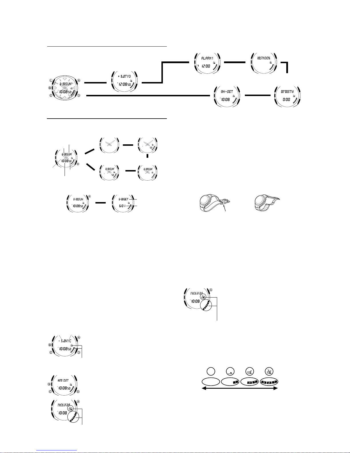
2. OPERATION CHART: QW-2708
General Guide
• Press C to change from mode to mode.
• In any mode, press L to illuminate the display.
Timekeeping Mode
Press C.
World Time Mode
▲
▲
Alarm Mode
Hand Setting Mode
Data Memory
▲
Mode
▲
Stopwatch Mode
▲
Timekeeping
Use the Timekeeping Mode to set and view the current time and date.
• In the Timekeeping Mode, press D to change the screen format as shown
below.
Date and Time
Month – Day
Day of week
Press D.
Analog
▲
Seconds
▲
▲
Seconds and Date
PM
indicator
• Pressing A displays the Last Signal screen (date and time the time
calibration signal was last received) in the Timekeeping Mode.
Seconds
Hour : Minutes
▲
▲
Press A.
▲
▲
Date
Receive date
Receive time
Last Signal Screen
Current Time Setting
This watch automatically adjusts its time setting in accordance with a time
calibration signal. You can also perform a manual procedure to set the time and
date, when necessary.
• Before using the watch in the Continental United States, first use the
procedure under
States” to set the time in accordance with a time calibration signal.
• Note that after you set your Home City (the city where you normally use the
watch) code, you must also turn on the watchís time calibration signal
receiver if you want to enable auto time calibration. See “About Auto Receive
for more information.
• See “Setting the Digital Time and Date Manually” for information about
manual settings.
• The analog time of this watch is synchronized with the digital time. Because
of this, the analog time setting is automatically adjusted whenever you
change the digital setting. See “Analog Timekeeping” for more information.
• Before using the watch in Japan, first specify your Home City, select the DST
setting you want to use, and then perform the procedure under “To perform
manual time calibration signal reception” .
Setting Up the Watch for Use in the Continental United States
You need to make the following three settings before using this watch in the
Continental United States. The following provides a general overview of the
setting procedure. For full details, see
and “Time Calibration Signal Reception”.
• Specify the city code for your Home City (the city where you will normally use
the watch).
• Select the auto summer time (DST) setting.
• Perform the manual time calibration signal receive operation to set the
current time.
To set up the watch for use in the Continental United States
GMT differential
l
l
l
City code
l
l
l
l
l
l
l
l
l
l
l
l
l
l
l
l
Receive indicator
l
l
l
l
l
l
l
l
l
l
l
l
l
l
l
l
l
l
l
l
l
l
l
l
l
l
l
l
l
l
Receive indicator
“
Setting Up the Watch for Use in the Continental United
“
Setting the Time and Date Manually
1. In the Timekeeping Mode, press B. This causes
the current auto receive on/off setting (the receive
indicator) to flash, which indicates the setting
screen.
2. Press C twice to move the flashing to the city
code setting.
3. Use D(+) and A(–) to select the city code you
want to use as your Home City.
The following
•
in the Continental United States time zones.
LAX: Los Angeles, San Francisco, Las Vegas,
Seattle
DEN: Denver, El Paso
CHI: Chicago, Houston, Dallas/Fort Worth, New
Orleans
NYC: New York, Detroit, Miami, Boston
4. Press C to display the summer time (DST) setting
screen.
5. Use D to select A UTO DST.
• AUTO DST specifies auto switching between
Daylight Saving Time and Standard Time.
6. Press B to exit the setting screen.
• If you changed the digital time setting with the
above steps, the analog hands move at this time
l
l
l
to match it. Wait until the analog hands stop
l
l
moving before you advance to the next step.
l
l
l
7. Hold down A for about two seconds until the
l
l
receive indicator starts to flash on the display.
are the city codes for major cities
”
▲
• This indicates that signal reception has started.
• Time calibration signal reception takes from two to six minutes. Take care that
you do not move the watch during this time.
• If the watch is indoors, we recommend that you place the watch near a
window to allow better signal reception.
• After signal reception is complete, the display of the watch changes to the Last
Signal screen, and the analog time of the watch is adjusted automatically .
Time Calibration Signal Reception
This watch is designed to pick up a time calibration signal and update its time
setting in accordance with the signal. There are two different methods you can
use to receive the signal: Auto Receive and Manual Receive. With Auto
Receive, the watch automatically receives the calibration signal three times
each day and makes appropriate adjustments. With Manual Receive, you
perform a specific button operation to receive the calibration signal.
Before performing a signal receive operation, remove the watch from you wrist
and position it as shown in the illustrations below.
• If your watch has a resin band, pass the end of the band through the band
loop and place the watch on a stable surface.
Resin band Metal band
Pass through band loop.
Note
• If you are using the time calibration signal to set the time for this watch, be
sure to correctly set your Home City. Otherwise, there is the chance that the
watch will not set the correct time.
• Note that signal reception is possible only when the watch is within range of a
time calibration signal transmitter, and a city code that supports signal
reception is selected as the Home City code.
• The current time setting in accordance with the time calibration signal takes
priority over any time settings you make.
”
• Auto receive is turned on when the watch is shipped from the factory.
• Time calibration signal reception is disabled while the analog hands are
moving after you change the digital time setting.
• See the information under
experience problems with time calibration signal reception.
To perform manual time calibration signal reception
1.Place the watch on a stable surface so its top (12 o'clock side) is facing in
the general direction of the signal transmitter.
• Note that signal reception is poor if the watch is on its back or side.
l
l
l
l
l
l
l
l
l
l
l
l
l
l
l
l
l
l
l
l
l
l
l
Receive indicator
Note
• To interrupt a receive operation and return to the Timekeeping Mode, press A.
• If the receive operation is unsuccessful, the message ERROR! appears on
the display for about one or two minutes. After that, the watch returns to the
Timekeeping Mode.
• You can also change from the Last Signal or ERROR! screen to the normal
timekeeping screen by pressing A.
About the Receive Indicator
The receive indicator shows the strength of the calibration signal being received.
For best reception, be sure to keep the watch in a location where signal strength is
strongest.
Weak
• Even in an area where signal strength is strong, it takes about 10 seconds for
signal reception to stabilize enough for the receive indicator to indicate signal
strength.
• Use the receive indicator as a guide for checking signal strength and for
finding the best location for the watch during signal receive operations.
• The receive indicator remains on the display in all modes following reception
of the time calibration signal and calibration of the watch’s time setting. The
receive indicator does not appear if signal reception was unsuccessful or
after manual adjustment of the current time setting.
“
Time Calibration Signal Reception” if you
2.In the Timekeeping Mode, hold down A for about
two seconds until the receive indicator starts to
flash on the display.
• This indicates that signal reception has started.
• Time calibration signal reception takes from two to
l
l
l
six minutes. Take care that you do not move the
l
l
watch during this time.
l
l
l
• After signal reception is complete, the display of the
watch changes to the Last Signal screen, and the
analog time of the watch is adjusted automatically.
• The receive indicator indicates that the calibration
time reception attempt was successful.
Strong
— 4 —
Page 7
About Auto Receive
When auto receive is turned on, the watch automatically starts to receive the
time calibration signal when the digital time in the Timekeeping Mode reaches
2:00 AM, 4:00 AM and 6:00 AM each day (calibration times).
Note
• The auto receive operation is performed only if the watch is in the
Timekeeping or World Time Mode when one of the calibration times is
reached.
It is not performed if a calibration time is reached while you are making
settings (while settings are flashing on the display), while an alarm is
sounding, or while a silent alert operation is being performed.
• Auto receipt of the calibration signal is designed to be performed early in the
morning, while you sleep (provided that the digital time is set correctly).
Before going to bed for the night, remove the watch from your wrist, and put it
in a location where it can easily receive the signal.
• The receive indicator indicates that either the 2:00 AM, 4:00 AM, or 6:00 AM
calibration signal reception was successful. Note, however, that the receive
indicator is cleared from the display at 3:00 AM each day.
• If you do not see the receive indicator except for the above reason, it means
there was some problem with the calibration reception operation. Either
perform reception manually, or make sure the watch is set up properly to
receive the time calibration signal for the next automatic reception time.
• When auto receive is turned on, the watch receives the calibration signal for
two to six minutes each day when the digital time reaches 2:00 AM, 4:00 AM
and 6:00 AM. Do not operate any of the watch’s buttons within six minutes
prior to or following the calibration times. Doing so can interfere with correct
calibration.
• Remember that reception of the calibration signal depends on the time
shown on the digital display. The receive operation will be performed
whenever the digital display shows 2:00 AM, 4:00 AM and 6:00 AM,
regardless of whether or not the displayed time is actually the correct time.
• When two or three receptions are successful, the watch uses the data of the
last reception for calibration. When only one reception is successful, the
watch uses the data of the successful reception.
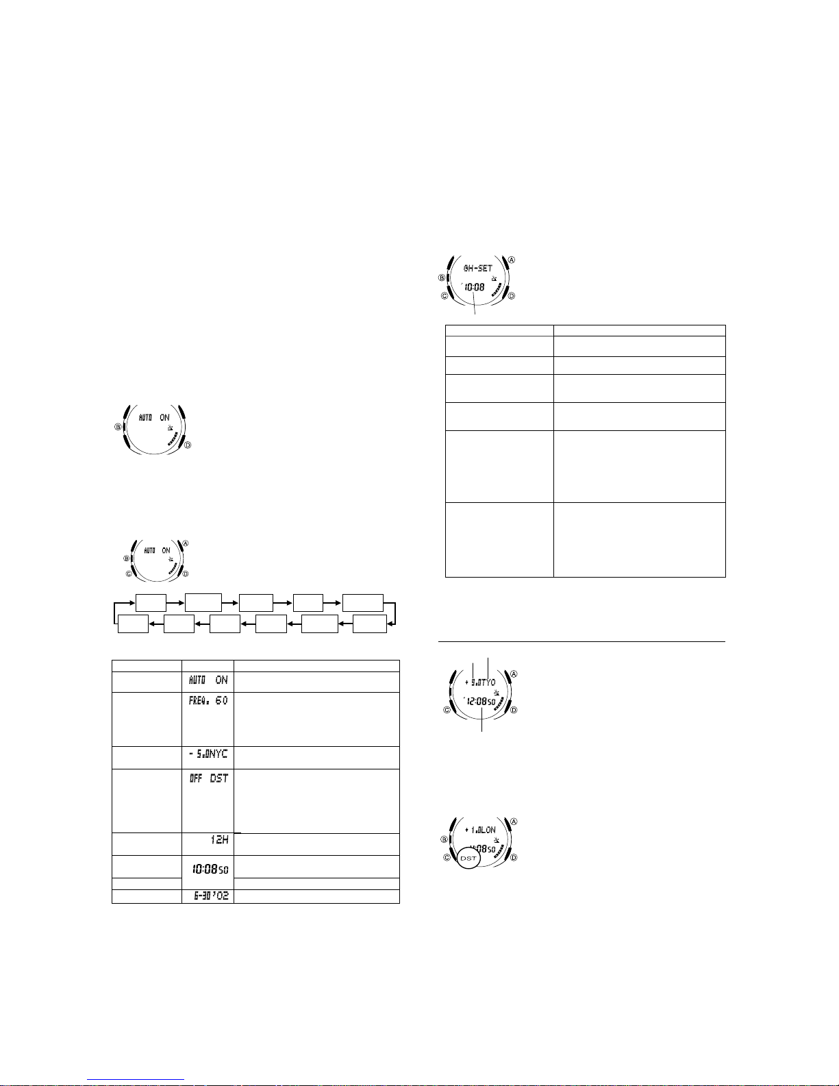
To turn auto receive on and off
Setting the Digital Time and Date Manually
Make sure you select your Home City code (the city code whose time and date
you are setting) before change the current time and date settings. World Time
Mode times are all displayed in accordance with the Timekeeping Mode
settings. Because of this, World Time Mode times will not be correct if you do
not select the proper Home City code before setting the time and date in the
Timekeeping Mode.
To set the current digital time and date manually
Auto
Receive
Day
3.When the setting you want to change is flashing, use A and/or D to
change it as described below.
Auto Receive
Frequency
City code
DST
12/24-Hour format
Hour, Minutes
Seconds
Month, Day, Year
4.Press B to exit the setting screen.
• The auto receive setting is used for time calibration signal reception only. See
“
About Auto Receive” for details.
• See “City Code Table” at the back of this manual for a complete list of
available city codes.
• Resetting the seconds to 00 while the current count is in the range of 30 to
59 causes the minutes to be increased by 1. In the range of 00 to 29, the
seconds are reset to 00 without changing the minutes.
1.In the Timekeeping Mode, press B. This causes
the current auto receive on/off setting (the receive
l
l
l
l
l
l
l
l
l
l
l
l
l
l
l
l
l
l
l
l
l
l
l
Month
indicator) to flash, which indicates the setting
l
l
screen.
l
l
l
2.Press D to toggle auto receive on (ON) and off
l
l
l
(OFF).
3.Press B to exit the setting screen.
1.In the Timekeeping Mode, press B. This causes
the current auto receive on/off setting (the receive
l
l
indicator) to flash, which indicates the setting
l
l
l
screen.
l
l
l
l
2.Press C to move the flashing in the sequence
shown below to select other settings.
Frequency
ScreenSetting
City Code
Year Minutes
Button Operations
Press D to toggle auto receive on and off.
When TYO (Tokyo) is selected as the city
code, press D to toggle the calibration
signal reception frequency among Auto
(FREQ. A T), 40KHz (FREQ. 40) and 60KHz
(FREQ. 60). Note that frequency selection is
available for the TYO city code only.
Use D (+) and A (–) to change the setting.
Press D to toggle between Daylight Saving
Time (ON) and standard time (OFF).
• Pressing D performs a different operation
when HKG, TYO, SEL, NYC, CHI, DEN,
LAX, ANC or HNL is selected as Home City
Code. See "Auto Summer Time (DST)
Switching".
Press D to toggle between 12-hour (12H)
and 24-hour (24H) timekeeping.
Use D (+) and A (–) to change the
setting.
Press D to reset the seconds to 00.
Use D (+) and A (–) to change the setting.
DST
Hour
12/24-Hour
Format
Seconds
Analog Timekeeping
The analog time of this watch is synchronized with the digital time. The analog
time setting is adjusted automatically whenever you change the digital time.
Note
• The hands for the analog timepiece move to adjust to a new setting whenever
any of the following occurs.
When you change the digital time setting manually
When the digital time setting is changed by time calibration signal reception
When you change the Home City code and/or DST setting
• If the analog time does not match the digital time for any reason, use the
procedure described under
setting to the digital setting.
• Whenever you need to adjust both the digital and the analog time settings
manually, make sure you adjust the digital setting first.
• Depending on how much the hands have to move in order to adjust to the
digital time, it may take some time before the analog hands stop moving.
To adjust the analog time
l
l
l
l
l
l
l
l
l
l
l
l
l
l
l
l
l
Current time
When you want to do this:
Move the hand setting
forward 20 seconds
Move the hand setting
back 20 seconds
Move the hand setting a short
way forward at high speed
Move the hand setting a
short way back at high speed
Move the hand setting a
long way forward at high
speed
Move the hand setting a
long way back at high
speed
4.Press B to exit the setting screen.
• The minute hand will be adjusted slightly to match the seconds when you exit
the setting screen.
• To return to the Timekeeping Mode, press C.
“
To adjust the analog time” to match the analog
1.In the Timekeeping Mode, press C five times to
enter the Hand Setting Mode.
2.Press B and the current digital time starts to
flash, which indicates the setting screen.
3. Use D (+) and A (–) to adjust the analog setting
as described below.
Perform this button operation:
• Press D.
• Press A.
• Hold down D.
• Release D when the hands reach the
setting you want.
• Hold down A.
• Release A when the hands reach the
setting you want.
• While holding down D to move the hands
at high-speed, press A to lock the highspeed hand movement.
• Press any button when the hands are
close to the setting you want.
• Hand movement stops automatically if the
hour hand makes one full (12-hour)
revolution.
• While holding down A to move the hands
at high-speed, press D to lock the highspeed hand movement.
• Press any button when the hands are
close to the setting you want.
• Hand movement stops automatically if the
hour hand makes one full (12-hour)
revolution.
World Time
GMT
City code
differential
Current time in the
selected city code
To view the time in another city code
While in the World Time Mode, press D to scroll through the city codes (time
zones) to the east or A to scroll to the west.
• If the current time shown for a city is wrong, check your Timekeeping Mode
time and Home City settings and make the necessary changes.
To toggle a city code time between standard time and Daylight Saving Time
• Note that the DST/Standard Time setting affects only the currently displayed
city code. Other city codes are not affected.
• Daylight Saving Time (DST) advances the time setting by one hour from
Standard Time. Remember that the not all countries or even local areas use
Daylight Saving Time .
• Note that you cannot use the World Time Mode to change the DST ON/OFF
setting of the Home City code you currently have selected in the Timekeeping
Mode. See information about turning the Home City code DST setting on and
off.
• The watch will perform a signal receive operation even if it is in the World
Time Mode when a calibration time is reached. If this happens, the World
Time Mode time settings will be adjusted in accordance with the Timekeeping
Mode’s Home City code time.
World Time shows the current time in 30 cities (29
time zones) around the world.
• For full information on city codes, see the
Code T able” at the back of this manual.
• The current time for all city codes in the World Time
Mode is calculated in accordance with the
Greenwich Mean Time (GMT) differential for each
city, based on the your Home City time setting.
• All of the operations in this section are performed in
the World Time Mode, which you enter by pressing
C.
1.In the World Time Mode, use A and D to display
the city code (time zone) whose standard time/
Daylight Saving Time setting you want to change.
2.Press B to toggle Daylight Saving Time (DST
displayed) and standard time (DST not displayed).
• The DST indicator is on the display whenever you
display a city code for which Daylight Saving Time
is turned on.
“
City
— 5 —
Page 8

Alarms
Alarm on indicator
Alarm screen
name
Alarm time
Alarm name indicator
To display Alarm Mode screen
In the Alarm Mode, use D to cycle through the alarm screens as shown
below.
ALARM1
Alarm1
Alarm2
Alarm3
Alarm4
To set an alarm
l
l
l
l
l
l
l
l
l
l
l
l
• Selecting the text causes the text input cursor to appear. You can input up
to eight characters of reminder text for each alarm.
• There are eight spaces in the text, so you have to press C eight times to
move to the Hour setting.
4.When the setting you want to change is selected, use A and D to change
it.
• While the hour or minute setting is flashing, use D (+) and A (–) to
change it.
• When setting the alarm time using the 12-hour format, take care to set the
time correctly as a.m. (no indicator) or p.m. (P indicator).
• When inputting text, use A and D to cycle through characters at the
current cursor location, and C to move the cursor to the right. See
“
Inputting T ext” for more information.
5.Press B to exit the setting screen.
• If you input reminder text, the text appears in place of the alarm screen name
when you exit the setting screen.
• If the reminder text has more than six characters, it will scroll from right to left
whenever it is displayed.
Alarm Operation
The following table describes the different types of alarm operations that this
watch can perform.
Alarm on indicator
Snooze
Alert on
indicator
indicator
• Press any button to stop the alarm after it starts to sound.
• If any alarm operation (one-time alarm, silent alert, snooze) occurs while a
signal receive operation is in progress, the receive operation is canceled.
• In the case of the snooze alarm, the alarm operation repeats up to seven
times every five minutes until the alarm is turned off.
• If you input reminder text for an alarm, the text appears for one minute in
place of the date on the Timekeeping Mode screen. The text is cleared from
the Timekeeping Mode screen if you change to another mode while it is
displayed.
• Alarm operations and the Hourly Time Signal operation are performed in all
modes.
• See information about selecting the alarm operation type.
The Alarm Mode gives you a choice of four one-time
alarms and one snooze alarm. You can select either
an audible beeper or flashing silent alert to let you
know when any of the alarm times is reached.
You can also input reminder text that appears when
the alarm time is reached.
Also use the Alarm Mode to turn the Hourly Time
Signal on and off.
• All of the operations in this section are performed
in the Alarm Mode, which you enter by pressing
C.
ALARM2
Snooze
ALARM3 ALARM4
• The following alarm screen names appear in the
center of the display to indicate the alarm whose
screen is currently displayed.
ALARM1 through ALARM4: One-time alarm
screen
SNOOZE: Snooze alarm screen
SIGNAL: Hourly Time Signal screen
• The currently displayed alarm screen is also
indicated by the alarm name indicators along the
bottom left of the watch’s display.
1.In the Alarm Mode, use D to select the alarm
whose time you want to set.
2.Press B and the hour setting of the alarm time
starts to flash, which indicates the setting screen.
• Pressing A and D at the same time resets the
alarm time to 12:00 AM, and clears the reminder
text in the upper part of the display (if there is
any).
3.Press C to move the flashing in the sequence
shown below to select other settings.
MinutesHour
Alarm Operation
Type
Alarm off
Alarm on
Alert on
SNOOZE
Text
Description
• Nothing happens when the alarm
time is reached.
• The alarm on indicator and alarm
name indicator flash on the
display for 10 seconds.
• The watch beeps for 10 seconds.
• The alert on indicator and alarm
name indicator flash on the
display for 10 seconds.
• The watch does not beep.
SIGNAL
To test the alarm
In the Alarm Mode, hold down D to sound the alarm.
To select the alarm operation type
1.In the Alarm Mode, use D to select the screen for the alarm (ALARM1 to
ALARM4, or SNOOZE) whose alarm type you want to select.
2.Press A to cycle through the available settings in the sequence shown
below.
Alarm onAlarm off
• The alarm on indicator ( ) and alarm name indicator are displayed for
each alarm (1 through 4, snooze) for which alarm on is set. The alert on
indicator
( ) and alarm name indicator are displayed for each alarm (1 through 4,
snooze) for which alert on is set.
• In other modes besides the Alarm Mode, the alarm name indicator is
displayed for each alarm for which alarm on is selected.
• In all modes, the alarm on indicator or alert on indicator is shown for any
alarm (ALARM1 through ALARM4, or SNOOZE) that is currently turned
on.
To turn the Hourly Time Signal on and off
1.In the Alarm Mode, use D to select the Hourly
Time Signal (SIGNAL).
2.Press A to toggle it on (SIG displayed) and off
(SIG not displayed).
• The Hourly Time Signal on indicator (SIG) is
shown on the display in all modes while this
function is turned on.
Alert on
Data Memory
Remaining memory
To create a new data memory record
Cursor
l
l
l
l
l
l
l
l
l
Text
Record number
To recall data memory records
1.In the Data Memory Mode, press A to scroll forward through data memory
records.
• Each press of A advances to the next record and shows its record
number and first six characters of its text.
• Pressing A while the last record in memory is on the display changes to
the remaining memory screen. Pressing A again displays the first record.
2.Press D to scroll through the text on the screen.
First six characters
You can use the watch’s data memory to store e-mail
addresses, Web page URLs, and other text data.
• All of the operations in this section are performed
in the Data Memory Mode, which you enter by
pressing C.
Data Memory Records
Each data memory record can contain up to 63
characters. Records are stored in memory in the
sequence they are created.
• The number of records you can store in data
memory depends on the number of characters that
make up each record. See
Management
1.In the Data Memory Mode, press A and D at the
same time to display the remaining memory
screen.
• You do not have to perform the above step if the
remaining memory screen is already on the
display.
• If REST 0% is shown for remaining memory, it
means that memory is full. To store another
record, you will first have to delete some of the
records stored in memory.
2.Press B and the flashing cursor appears on the
display, which indicates the setting screen.
3.Use A and D to cycle through characters at the
current cursor location, and C to move the cursor
to the right. See
information.
• If memory becomes full while you are inputting
text, the cursor will jump to the first (leftmost)
character of the text when you press C, instead
of advancing to the right.
4.Press B to store your data and return to the data
memory record screen (without the cursor).
• The message SAVE! appears for about two
seconds, followed by a data memory record screen,
which shows the text you just input in the upper
part of the display, and a record number
automatically assigned by the watch in the lower
part of the display.
• While the record number is in the lower part of the
display, you can see only six characters of the text
in the record. You can scroll through the text on the
screen by pressing D. See
records
”
for more information.
”
on the next page for more information.
▲
“
Data Memory
“
Inputting T ext” for more
“
T o recall data memory
▲
End mark
Pressing D scrolls through the text.
• An end mark indicates the end of the text.
— 6 —
Page 9

To edit a data memory record
1.In the Data Memory Mode, display the record you want to edit.
2.Press B and the flashing cursor appears on the display.
3.Press C to move the flashing to the character you want to change.
4.Use D and A to change the character.
5.After making the changes you want, press B to store them and return to the
data memory record screen.
To delete a data memory record
1.In the Data Memory Mode, display the record you want to delete.
2.Press B and the flashing cursor appears on the display.
3.Press A and D at the same time to delete the record.
• The message CLEAR! appears to indicate that the record is being deleted.
After the record is deleted, the cursor appears on the display, ready for
input.
4.Input data or press B to return to the remaining memory screen.
Stopwatch
Seconds
1/100 second
Hours
Minutes
To measure times with the stopwatch
Elapsed Time
D
Start Stop
Split Time
D
Start Split
Two Finishes
D
Start Split
D
➤
A
➤
(SPL displayed)
A
➤
First runner
finishes.
Display time of
first runner.
The stopwatch lets you measure elapsed time,
split times, and two finishes.
• The display range of the stopwatch is 23 hours,
59 minutes, 59.99 seconds.
• The stopwatch continues to run, restarting from
zero after it reaches its limit, until you stop it.
• Exiting the Stopwatch Mode while a split time is
frozen on the display clears the split time and
returns to elapsed time measurement.
• The stopwatch measurement operation
continues even if you exit the Stopwatch Mode.
• All of the operations in this section are
performed in the Stopwatch Mode, which you
enter by pressing C.
D
➤
Re-start Clear
A
➤
Split release
D
➤
Stop
Second runner
finishes.
D
➤
Stop
D
➤
Stop
A
➤
Split release
Display time of
second runner.
A
➤
A
➤
Clear
A
➤
Clear
Reference
This section contains more detailed and technical information about watch
operation. It also contains important precautions and notes about the various
features and functions of this watch.
Auto Return Features
• If you leave the watch in the Alarm, Data Memory, or Hand Setting Mode for
two or three minutes without performing any operation, it automatically
changes to the Timekeeping Mode.
• If you leave a screen with flashing digits or a cursor on the display for two or
three minutes without performing any operation, the watch automatically
saves anything you have input up to that point and exits the setting screen.
Data and Setting Scrolling
The A and D buttons are used in various modes and setting screens to scroll
through data on the display. In most cases, holding down these buttons during
a scroll operation scrolls through the data at high speed.
Initial Screens
When you enter the Alarm or World Time Mode, the data you were viewing
when you last exited the mode appears first.
Time Calibration Signal Reception
• This watch is designed to receive a time calibration signal originating from
one of the three transmitters listed below.
• When you select one of the city codes shown below as your Home City code,
the watch sets up automatically to receive from the applicable transmitter.
Time calibration signal reception is not possible whenever any other city code
is specified as the Home City code.
• When you select TYO as y our Home City code , the w atch automatically
selects either the Fukushima signal (40kHz) or the Fukuoka/Saga signal
(60kHz), depending on which is stronger.
LAX, DEN, CHI, NYC
• Note that when TYO (Japan) is selected as the Home City code, y ou can
specify one of two different time signal transmitters .
Location
Fort Collins, Colorado
Fukushima, Japan
Fukuoka/Saga, Japan
Home City Code
TYO
WWVB
JJY
JJY
Frequency
60kHz
40kHz
60kHz
Call Sign
Received Transmitter
Fort Collins, Colorado
Fukushima or Fukuoka/Saga, Japan
(selectable)
1,200 miles
• Signal reception is possible within a radius of about 2,000 miles (3,000
kilometers) from the Fort Collins transmitter.
• At distances further than about 500 kilometers from the Fukushima and
Fukuoka/Saga transmitter, the signal may become weak and reception may
be impossible under certain conditions.
General Precautions
• The watch is designed to automatically update the date and day of the week
for the period January 1, 2000 to December 31, 2039. Setting of the date by
the time calibration signal cannot be performed starting from January 1,
2040.
• This watch can receive signals that differentiate between leap years and nonleap years.
• Even when the watch is within the reception range of the transmitter, signal
reception is impossible if the signal is blocked by mountains or other
geological formations between the watch and signal source.
• Signal reception is affected by weather, atmospheric conditions, and
seasonal changes.
• The time calibration signal is bounced off the ionosphere. Because of this,
such factors as changes in the reflectivity of the ionosphere, as well as
movement of the ionosphere to higher altitudes due to seasonal atmospheric
changes or the time of day may change the reception range of the signal and
make reception temporarily impossible.
• Reception is best when the antenna built into the 12 o'clock edge of the
watch is facing in the general direction of the signal transmitter. Note,
however, that moving the watch while the time calibration signal receive
operation is taking place will make stable reception impossible.
• Think of the watch as acting like a TV or radio when it is receiving the
calibration signal. When receiving indoors, move to a location as near as
possible to a window.
• Proper signal reception can be difficult or even impossible under the
conditions listed below.
Near TVs, refrigerators, computers, or other household appliances
Far away from broadcasting stations among ferro-concrete structures or near
mountains
Underground, in tunnels or in ferro-concrete buildings
Near high-tension wires, neon signs, or radio stations with interfering
frequencies
Near railroads, highways or airports
In trains or cars
• Radio interference can make signal reception impossible.
• Strong electrostatic charge can result in the wrong time being set.
• If you are in an area where proper time calibration signal reception is
impossible, the watch keeps time with the precision noted in
Troubleshooting
Check the following points whenever you experience problems with your watch.
Problem
Cannot perform
manual receive.
Auto receive is
turned on, but
the receive
indicator does
not appear on
the display.
Time setting is
incorrect
following signal
reception.
Auto Summer Time (DST) Switching
The time calibration signal transmitted from Fort Collins, Colorado includes
both standard time and summer time (Daylight Saving Time) data. When auto
summer time (DST) switching is turned on, the watch switches between
standard time and summer time (DST) automatically in accordance with the
Fort Collins signal.
• Daylight Saving Time (DST) advances the time setting by one hour from
Standard Time. Remember that not all countries or even local areas use
Daylight Saving Time .
• The time calibration signals transmitted from the Fukushima and Fukuoka/
Saga do not include summer time data.
• When using the watch in the Continental United States or in Japan, select
AUTO DST for the auto summer time setting.
• The default auto summer time settings is AUTO DST whenever you select
one of the following city codes as your Home City code: HKG, TYO, SEL,
NYC, CHI, DEN, LAX, ANC, or HNL.
• If you experience problems receiving the time calibration signal in your area,
it is probably best to turn off auto time switching.
• See information about configuring summer time (DST) settings manually.
To select the auto summer time setting
1. In the Timekeeping Mode, press B. This causes the current auto receive on/
off setting (the receive indicator) to flash, which indicates the setting screen.
2. Press C three times until the summer time (DST) setting screen appears.
3. Use D to cycle through the summer time settings in the sequence shown
below.
2,000 miles
Fort Collins
The watch is not in the Timekeeping Mode.
•
You changed the time setting manually.
•
The watch was not in the Timekeeping
or World Time Mode, or you were
performing some button operation
during the auto signal receive operation
was performed.
•
Even if receive is successful, the receive
indicator disappears every day at 3am.
•
If the time is one hour off, the DST setting
may be incorrect.
•
The Home City Code setting is not
correct for the area where you are using
the watch.
500
kilometers
Fukuoka/Saga
1,000
kilometers
Probable Cause
What you should do
Enter the Timekeeping Mode
and try again.
•
Perform manual signal receive
or wait until the next auto
signal receive operation is
performed.
•
Check to make sure the watch
is in a location where it can
receive the signal.
•
Put the watch in a location
that is suitable for good
reception.
•
Change the DST setting to
AUTO DST.
•
Select the correct Home City
Code.
500
kilometers
Fukushima
1,000
kilometers
“
Specifications.
4. When the setting y ou want is selected, press B to exit the setting screen.
”
— 7 —
Page 10

Timekeeping
• The day of the week is automatically displayed in accordance with the date
(year, month, and day) settings.
• The year can be set in the range of 2000 to 2039.
• The watchís built-in full automatic calendar automatically makes allowances
for different month lengths and leap years. Once you set the date, there
should be no reason to change it except after you have the watchís battery
replaced.
• The current time for all city codes in the Timekeeping Mode is calculated in
accordance with the Greenwich Mean Time (GMT) differential for each city,
based on the your Home City time setting.
• GMT differential is calculated by this watch based on Universal Time
Coordinated (UTC
The letters “UTC” stands for “Universal Time Coordinated,” which is the
*
world-wide scientific standard of timekeeping. It is based upon carefully
maintained atomic (cesium) clocks that keep accurate to within
microseconds. Leap seconds are added or subtracted as necessary to keep
UTC in sync with the Earth’s rotation. The reference point for UTC is
Greenwich, England.
12-hour/24-hour Timekeeping Formats
The 12-hour/24-hour timekeeping format you select in the Timekeeping Mode
is also applied in all other modes.
• With the 12-hour format, the P (PM) indicator appears on the display for
times in the range of noon to 11:59 p.m. and the no indicator appears for
times in the range of midnight to 11:59 a.m.
• With the 24-hour format, times are displayed in the range of 0:00 to 23:59,
with 24 indicator.
Inputting Text
The following describes how to input text in the Alarm and Data Memory
Modes.
To input characters
Cursor
l
l
l
l
l
l
l
l
l
Reminder Text Input
Screen
2.When the character you want is at the cursor position, press C to move the
cursor to the right.
3.Repeat steps 1 and 2 to input the rest of the characters you want.
• See the “Character List” at the back of this manual for information about
the characters you can input.
Data Memory Management
Data memory can hold up to 315 characters total, while each record can
contain up to 63 characters. This means that 40 records can be stored in data
memory when each record contains seven characters of text or less.
Backlight Precautions
The backlight uses an EL (electro-luminescent) panel that causes the entire
display to glow for easy reading in the dark.
In any mode, press L to illuminate the display for about one second.
• The electro-luminescent panel that provides illumination loses power after
very long use.
• The illumination provided by the backlight may be hard to see when viewed
under direct sunlight.
• The watch may emit an audible sound whenever the display is illuminated.
This is due to vibration of the EL panel used for illumination, and does not
indicate malfunction.
• The backlight automatically turns off whenever an alarm sounds.
• Frequent use of the backlight shortens the battery life.
) data.
*
1.When the cursor is on the display, use A and D
to cycle through the available letters, numbers and
symbols, in the sequence shown below.
Press D.
(space)
0
to
9
(number)
a
to
(lower-case)
z
A
(upper-case)
Press A.
to
Z
to
*
(symbol)
+
— 8 —
Page 11

3. DRAWINGS
3-1. LCD DIAGRAMS
QW-2511
L 4
L 5
L 6
L 7
L 8
L 9
L10
L11
L12
L13
L14
L15
L16
L17
L18
L19
L20
L21
L22
L23
L24
L25
L26
L27
L28
L29
L30
L31
L32
alm0
alm1
alm2
alm3
alm4
W0
y4
y3
y2
y1
y0
p
a5
f5c5b5
e5
d5 d4
snz
X0
g5
alert
W1
a4
f4
g4
e4
24
e1 c1
dst
W2
col1
b4
c4
a1
f1
g1
d1
f3
col0
e3
b1
f0a0b0
e0
rc3
W3
a3
b3
g3
c3
d3 d2
g0
c0
d0
rc2
W4
rc3
rc2
X36
a2
b2
f2
g2
e2
c2
sig
rc1
rc1
SEG.
L4
L5
L6
L7
L8
L9
L10
L11
L12
L13
L14
L15
L16
L17
L18
L19
L20
L21
L22
L23
L24
L25
L26
L27
L28
L29
L30
COM.
LC1
x14y2
x13y2
x12y2
x11y2
x10y2
x9y2
x8y2
x7y2
x6y2
x5y2
x4y2
x3y2
x2y2
x1y2
x0y2
x19y2
x20y2
x21y2
x22y2
x23y2
x24y2
x25y2
x26y2
x27y2
x28y2
x29y2
x30y2
LC2
x14y1
x13y1
x12y1
x11y1
x10y1
x9y1
x8y1
x7y1
x6y1
x5y1
x4y1
x3y1
x2y1
x1y1
x0y1
x19y1
x20y1
x21y1
x22y1
x23y1
x24y1
x25y1
x26y1
x27y1
x28y1
x29y1
x30y1
LC3
x14y0
x13y0
x12y0
x11y0
x10y0
x9y0
x8y0
x7y0
x6y0
x5y0
x4y0
x3y0
x2y0
x1y0
x0y0
x19y0
x20y0
x21y0
x22y0
x23y0
x24y0
x25y0
x26y0
x27y0
x28y0
x29y0
x30y0
L57
L56
L55
L50
L49
L48
L47
L46
L45
L44
L43
L42
L41
L40
L39
L38
L37
L36
L35
L34
L33
LC3
LC2
LC2
x31y1
x32y1
x33y1
x34y1
x35y1
x36y1
rc1
b0
g0
b1
g1
b2
g2
b3
g3
e3
b4
g4
f4
b5
g5
f5
x18y1
x17y1
x16y1
x15y1
LC1
LC3
x31y0
x32y0
x33y0
x34y0
x35y0
x36y0
LC4
x31y4
x32y4
x33y4
x34y4
x35y4
x36y4
LC5
x31y3
x32y3
x33y3
x34y3
x35y3
x36y3
rc3
a0
f0
a1
f1
a2
w0
w1
w2
w3
w4
f2
d0
d1
d2
sig
dst
a3
f3
col1
a4
24
alert
snz
alm4
alm3
alm2
alm2
a5
p
x18y0
x17y0
x16y0
x15y0
x18y4
x17y4
x16y4
x15y4
alm1
alm0
x18y3
x17y3
x16y3
x15y3
LC5
LC4
L58
L60
L59
LC4
x14y4
x13y4
x12y4
x11y4
x10y4
x9y4
x8y4
x7y4
x6y4
x5y4
x4y4
x3y4
x2y4
x1y4
x0y4
x19y4
x20y4
x21y4
x22y4
x23y4
x24y4
x25y4
x26y4
x27y4
x28y4
x29y4
x30y4
LC5
x14y3
x13y3
x12y3
x11y3
x10y3
x9y3
x8y3
x7y3
x6y3
x5y3
x4y3
x3y3
x2y3
x1y3
x0y3
x19y3
x20y3
x21y3
x22y3
x23y3
x24y3
x25y3
x26y3
x27y3
x28y3
x29y3
x30y3
SEG.
L31
L32
L33
L34
L35
L36
L37
L38
L39
L40
L41
L42
L43
L44
L45
L46
L47
L48
L49
L50
L55
L56
L57
L58
L59
L60
COM.
LC1
x31y2
x32y2
x33y2
x34y2
x35y2
x36y2
rc2
c0
e0
c1
e1
c2
e2
c3
d3
col0
c4
d4
e4
c5
d5
e5
x18y2
x17y2
x16y2
x15y2
— 9 —
Page 12

QW-2708/2709
alm0
alm1
alm2
24
L 4
p
L 5
L 6
y4
y3
y2
y1
y0
X0
f5c5b5
e5
L 7
L 8
L 9
L10
a5
f4
g5
e4b4c4
d5 d4
L11
L12
L13
L14
L15
L16
L17
L18
L19
L20
L21
L22
L23
L24
L25
L26
L27
L28
L29
L30
L31
L32
X36
rc3
rc2
rc1
col1
a4
g4
col0
a3
f3c3b3
g3
e3
d3 d2
a2
f2
g2
e2b2c2
g1
e1 c1
d1 d0
b1a1f1
f0a0b0
g0
c0e0
rc1
rc2
SEG.
L4
L5
L6
L7
L8
L9
L10
L11
L12
L13
L14
L15
L16
L17
L18
L19
L20
L21
L22
L23
L24
L25
L26
L27
L28
L29
L30
COM.
LC1
x14y2
x13y2
x12y2
x11y2
x10y2
x9y2
x8y2
x7y2
x6y2
x5y2
x4y2
x3y2
x2y2
x1y2
x0y2
x19y2
x20y2
x21y2
x22y2
x23y2
x24y2
x25y2
x26y2
x27y2
x28y2
x29y2
x30y2
LC2
x14y1
x13y1
x12y1
x11y1
x10y1
x9y1
x8y1
x7y1
x6y1
x5y1
x4y1
x3y1
x2y1
x1y1
x0y1
x19y1
x20y1
x21y1
x22y1
x23y1
x24y1
x25y1
x26y1
x27y1
x28y1
x29y1
x30y1
alm3
LC3
x14y0
x13y0
x12y0
x11y0
x10y0
x9y0
x8y0
x7y0
x6y0
x5y0
x4y0
x3y0
x2y0
x1y0
x0y0
x19y0
x20y0
x21y0
x22y0
x23y0
x24y0
x25y0
x26y0
x27y0
x28y0
x29y0
x30y0
sigdst
alm4
alertsnz
L57
L56
L55
L50
L49
L48
L47
L46
L45
L44
L43
L42
L41
L40
L39
L38
L37
L36
LC5
LC4
L58
L60
L59
LC4
x14y4
x13y4
x12y4
x11y4
x10y4
x9y4
x8y4
x7y4
x6y4
x5y4
x4y4
x3y4
x2y4
x1y4
x0y4
x19y4
x20y4
x21y4
x22y4
x23y4
x24y4
x25y4
x26y4
x27y4
x28y4
x29y4
x30y4
LC5
x14y3
x13y3
x12y3
x11y3
x10y3
x9y3
x8y3
x7y3
x6y3
x5y3
x4y3
x3y3
x2y3
x1y3
x0y3
x19y3
x20y3
x21y3
x22y3
x23y3
x24y3
x25y3
x26y3
x27y3
x28y3
x29y3
x30y3
SEG.
COM.
L31
L32
L33
L34
L35
L36
L37
L38
L39
L40
L41
L42
L43
L44
L45
L46
L47
L48
L49
L50
L55
L56
L57
L58
L59
L60
L35
LC1
x31y2
x32y2
x33y2
x34y2
x35y2
x36y2
rc2
c0
e0
c1
e1
c2
e2
c3
d3
col0
c4
d4
e4
c5
d5
e5
x18y2
x17y2
x16y2
x15y2
rc3
L34
L33
LC3
LC2
LC1
LC2
x31y1
x32y1
x33y1
x34y1
x35y1
x36y1
rc1
b0
g0
b1
g1
b2
g2
b3
g3
e3
b4
g4
f4
b5
g5
f5
x18y1
x17y1
x16y1
x15y1
LC3
x31y0
x32y0
x33y0
x34y0
x35y0
x36y0
a0
f0
a1
f1
a2
f2
a3
f3
col1
a4
a5
p
x18y0
x17y0
x16y0
x15y0
LC4
x31y4
x32y4
x33y4
x34y4
x35y4
x36y4
x18y4
x17y4
x16y4
x15y4
LC5
x31y3
x32y3
x33y3
x34y3
x35y3
x36y3
rc3
d0
d1
d2
sig
dst
24
alert
snz
alm4
alm3
alm2
alm2
alm1
alm0
x18y3
x17y3
x16y3
x15y3
— 10 —
Page 13

— 11 —
GND VDD2
CRIN
BAT
VCH VDD3 VC1 VC2
C1
C3C8
XTB
Xtal1
L4 L60- - - - - LC1 LC5- - -
CT
LCD
LD1
CRMS
S2
S4
S3
VDD1
C2
VDD2A
BD1
GNDA
C9
Z
LL1
Tr1
CRST
XT
+
T1
T2
T3
KI1
KI2
KI3
KI4
KI5
KI6
KI7
KI8
KI9
EMP
S1
PZ
VDSP
C4
VOSC
C7
VC3 VC4
C5
VHF
C6
VAN
KC5
KC4
KC3
KC2
PX1
PY1
Vref
PW1
PY3
PX3
PU1
PZ1
LE
PH
ADIN
PO
KC6
KC1
AC
T4
L2L1
✽1✽1✽1✽1✽1✽1✽1 ✽1 ✽1 ✽1✽1
✽1
✽1
✽1
✽1
✽1
✽1
✽1
✽1
✽1
✽1
✽1
✽1
✽1
A2OUT
✽1
✽4 ✽4
+
✽1
Creg
PON
REG
AGC
VSM0
VSM1
TCOGND
HOLD
VCC
1
2
3
16
15
14
4
5
6
7
8
13
12
11
10
9
Cxt
C401
Rxt2
Ccp9
Cf12
Cagc
Cbat
Rbat
Xtal2
IC
ANT
Rant2
Cf13
Rcp
An.B
CLF1
E'
Cel
EL
INV
LL2
L+
VOUT
L-
GND
CLF2
V+
BACK
FRONT
PTINPTSCUTSCKSDOCSBSDILC6
Rxt3
Xtal3
✽2
✽2
✽2
✽3
✽1
✽3
✽3
✽1
S5
Ccont
C402
C403
C603
C602
C601
Rant1
Rcont
Rs
Rg
Rd
Cc
FET
L3,L51-54 ✽1
✽5
Rpd
TOTAL
BONDING
(LSI TEST AC, T1-3, KI1-9, L8-39)
129 Pins
96 Pins
LSI
✽ 1. No bonding
✽ 2. Short (Soldering)
✽ 3. Latch type key
✽ 4. O1 and O2 are used in this module.
✽ 5. An.B is not mounted in this module.
3-2. CIRCUIT DIAGRAM
QW-2511
Page 14

— 12 —
QW-2708/2709
GND VDD2
CRIN
BAT
VCH VDD3 VC1 VC2
C1
C3C8
XTB
Xtal1
L4 L60- - - - - LC1 LC5- - -
CT
LCD
LD1
CRMS
S2
S4
S3
VDD1
C2
VDD2A
BD1
GNDA
C9
Z
LL1
Tr1
CRST
XT
+
T1
T2
T3
KI1
KI2
KI3
KI4
KI5
KI6
KI7
KI8
KI9
EMP
S1
PZ
VDSP
C4
VOSC
C7
VC3 VC4
C5
VHF
C6
VAN
KC5
KC4
KC3
KC2
PX1
PY1
Vref
PW1
PY3
PX3
PU1
PZ1
LE
PH
ADIN
PO
KC6
KC1
AC
T4
L2L1
✽1✽1✽1✽1✽1✽1✽1 ✽1 ✽1 ✽1✽1
✽1
✽1
✽1
✽1
✽1
✽1
✽1
✽1
✽1
✽1
✽1
✽1
✽1
A2OUT
✽1
✽4 ✽4
+
✽1
Creg
PON
REG
AGC
VSM0
VSM1
TCOGND
HOLD
VCC
1
2
3
16
15
14
4
5
6
7
8
13
12
11
10
9
Cxt
C401
Rxt2
Ccp9
Cf12
Cagc
Cbat
Rbat
Xtal2
IC
ANT
Rant2
Cf13
Rcp
An.B
CLF1
E'
Cel
EL
INV
LL2
L+
VOUT
L-
GND
CLF2
V+
BACK
FRONT
PTINPTSCUTSCKSDOCSBSDILC6
Rxt3
Xtal3
✽2
✽2
✽2
✽3
✽1
✽3
✽3
✽1
S5
Ccont
C402
C403
C773
C772
C771
Rant1
Rcont
Rs
Rg
Rd
Cc
FET
L3,L51-54 ✽1
Rpd
TOTAL
BONDING
(LSI TEST AC, T1-3, KI1-9, L8-39)
129 Pins
96 Pins
LSI
✽ 1. No bonding
✽ 2. Short (Soldering)
KI6: Open (No Soldering)
KI7: Open (No Soldering)
KI8: Open (No Soldering)
✽ 3. Latch type key
✽ 4. O1 and O2 are used in this module.
Page 15

3-3. CHECKING TERMINALS AND COMPONENT
QW-2511
Capacitor/Chip
Cel
C9
Xtal2
Oscillator/Crystal
Xtal3
Oscillator/Crystal
Rxt2
Resistor/Chip
Rxt3
Resistor/Chip
Rbat
Resistor/Chip
Rant2
Resistor/Chip
Creg
Capacitor/Chip
C8
Capacitor/Tantalum
INV
GND
GND
16
16
2
7
XT2
LD1GND
XT3
XT2
3
GND
GND VOSC
VC3
VC1
VC4
VC2
GND
KI8
XT3
4
4
VDD2
VDD1
GND
GND
VDD3
GND
GND VHF
GND
KI6KI7
XT
XTB
VDSP
3. PCB ASS'Y
(7640 5306)
KI2
7
KI3
KI5
L2
L1
KI4
VOUT
L+
L-
GND
KI1
Capacitor/Tantalum
Rd
Resistor/ Chip
Cc
Capacitor/Chip
Cagc
Inverter
GND
L-
CLF2
VOUT
CLF1
L+
V
C
H
KI4
G
VCH
KC1
KC2
KI1
KI1
VDD2
VOUT
N
D
KC5
VC1
Capacitor/Chip
Resistor/Chip
Rcp
Cf13
GND
GND
E'
VDD2
CLF2
V+
CLF1
L2
GND
GND
VDD2
Capacitor/Chip
Ccp9
Capacitor/Chip
Cf12
GND
cp
GND
GND12GND
cp
14
13
1
16
2S
1
2
KC3
316542
1
D
57
GND
D
GND
S
S
D
VOSC
LL1
LL1
VDD2
Capacitor/
Chip
IC
9
9
121314
KI9
KC4
8
GND
7
KI2
GND
G
KI9
G
GND
LD1
LD1
3
GND
KI9
XT
GND
AC
KI5
G
N
D
L
L
1
LL1
GND
KI3
5.
Xtal1
Oscillator/Crystal
(7110 1263)
C3
Capacitor/Chip
C4
Capacitor/Chip
C6
Capacitor/Chip
C1
Capacitor/Chip
C7
Capacitor/Chip
C2
Capacitor/Chip
C5
Capacitor/Chip
LL2
Resistor/Chip
Rs
Coil
FET
Capacitor/Chip
Cxt
— 13 —
Resistor/Chip
Rg
Transistor
Resistor/Chip
Rpd
Tr1
Capacitor/Chip
Cbat
CT
4. Capacitor/Trimmer
(1001 0950)
Coil
LL1
Z
Varistor
Transistor
Page 16

QW-2708/2709
Xtal2
Oscillator/Crystal
Xtal3
Rxt2
KI2
7
XT3
4
XT2
3
LD1GND
GND
GND VOSC
VC3
VC4
4
XT2
VC1
VC2
GND
KI8
7
KI3
KI5
Oscillator/
Crystal
Resistor/Chip
Rxt3
Rbat
GND
16
16
2
XT3
VDD2
VDD1
GND
VDD3
VDSP
GND
GND VHF
GND
GND
KI6KI7
C8
Resistor/Chip
Resistor/Chip
Rant2
Resistor/
Chip
Creg
Capacitor/
Chip
GND
L1
XT
XTB
QW-2708:
3a. PCB ASS'Y
(7640 5313)
QW-2709:
3b. PCB ASS'Y
(7640 5305)
Capacitor/Tantalum
Inverter
INV
Cel
L2
KI4
VOUT
L+
L-
GND
KI1
Cagc
Capacitor/Chip
Capacitor/
Chip
C9
KI4
KC1
KC2
KI1
KI1
Resistor/Chip
Rcp
Capacitor/
Tantalum
GND
LVOUT
L+
V
C
H
VDD2
VOUT
G
N
D
VCH
KC5
VC1
Cf13
E'
CLF2
CLF1
V+
Capacitor/Chip
GND
GND
VDD2
CLF2
CLF1
L2
GND
GND
Ccp9
Capacitor/Chip
Cf12
1
2S
VDD2
GND
GND
cp
14
1
16
2
D
GND
D
S
LL1
LL1
Capacitor/
Chip
9
cp
GND12GND
13
9
121314
KI9
KC3
KC4
8
GND
7
316542
1
57
GND
GND
G
G
S
LD1
D
LD1
GND
XT
GND
AC
G
N
VOSC
D
L
L
1
LL1
VDD2BD1
GND
IC
KI2
KI9
GND
3
KI9
KI3
KI5
5.
Xtal1
Oscillator/Crystal
(7110 1263)
C3
Capacitor/Chip
C4
Capacitor/Chip
C6
Capacitor/Chip
C1
Capacitor/Chip
C7
Capacitor/Chip
C2
Capacitor/Chip
C5
Capacitor/Chip
Top view of P.C.B. ass'y Bottom view of P.C.B. ass'y
Coil
LL2
Capacitor/Chip
Cxt
— 14 —
Resistor/Chip
Rpd
Cbat
CT
Capacitor/Chip
LL1
Z
Varistor
Transistor
Tr1
4. Capacitor/Trimmer
(1001 0950)
Coil
Page 17

4. EXPLODED VIEW: QW-2511
1 (1007 6096)
15a (1007 6109)
15b (1007 6110)
13 (1007 6106)
23 (1007 6104)
12 (1007 6069)
3 (7640 5306)
PCB Ass'y
18 (7233 1757)
21 (7201 9249)
13 (1007 6106)
2 (1007 6108)
20 (1007 6101)
19 (1007 6102)
6 (7225 2421)
14 (1007 6103)
11 (1007 6098)
9 (1007 6100)
10 (7231 1952)
22 (1007 6097)
7 (1005 8521)
Battery Lithium
(CR2016)
16 (1007 6099)
8 (1007 6107)
17 (7233 0952)
7 (1005 8521)
— 15 —
Page 18

5. PARTS LIST: QW-2511
-
-
-
p
Note: 1. Prices and specifications are subject to change without prior notice.
2. Spare parts are classified as follows according to their importance in after-sales service.
A Rank -------------------------------------B Rank -------------------------------------C Rank --------------------------------------
3. Batteries in Bulk pack on the tray will be supplied from our Overseas Spare Parts Section under charge basis.
Batteries in Blister pack will be supplied from our Sales Department.
4. As for order/supply of spare parts, refer to the separate publication "GUIDE BOOK for spare parts supply".
Item Code No. Parts Name Specification Applicable Q R
MODULE/WITHOUT MOVEMENT QW-2511YC-02 WV-54DJ-7AV
MODULE/WITHOUT MOVEMENT QW-2511YC-03 WV-54KJ-9A
< The module QW-2511 is "built-in type" which is assembled directly to the case,
therefore the module as the spare parts is not available. >
1 1007 6096 LCD C2511-01P QW-2511YC Common 1 A
2 1007 6108 EL YEL-2511-A-01 QW-2511YC Common 1 A
3 7640 5306 PCB ASS'Y Q255488*1TK QW-2511YC Common 1 A
4 1001 0950 CAPACITOR/TRIMMER CTZ2E-30C-W2-P QW-2511YC Common 1 B
5 7110 1263 OSCILLATOR/CRYSTAL DT-26S07 QW-2511YC Common 1 B
6 7225 2421 CONTACT/BATTERY(-) Q34947C-2 QW-2511YC Common 1 C
7 1005 8521 CUSHION Q468515-1 QW-2511YC Common 2 C
8 1007 6107 CUSHION 2709-1 Q469338-1 QW-2511YC Common 1 C
9 1007 6100 HOLDER/ANTENNA Q469327-1 QW-2511YC Common 1 C
10 7231 1952 HOLDER/BATTERY Q253743-1 QW-2511YC Common 1 C
11 1007 6098 HOUSING 2511-1 Q152311A-1 QW-2511YC Common 1 C
12 1007 6069 HOUSING 2709-2 Q152304A-1 QW-2511YC Common 1 C
13 1007 6106 INTERCONNECTOR 2511-1 Q469335-1 QW-2511YC Common 2 C
14 1007 6103 INTERCONNECTOR 2709-2 Q469334-1 QW-2511YC Common 1 C
15a 1007 6109 PANEL Q370868-2 QW-2511YC-02 1 C
15b 1007 6110 PANEL Q370868-3 QW-2511YC-03 1 C
16 1007 6099 SHEET/INSULATION Q469326-1 QW-2511YC Common 1 C
17 7233 0952 SHEET/INSULATION 1028 Q434476-1 QW-2511YC Common 1 C
18 7233 1757 SHEET/INSULATION 1403 Q452985-1 QW-2511YC Common 1 C
19 1007 6102 SPRING/COIL 2511-1 Q469331-1 QW-2511YC Common 2 B
20 1007 6101 SPRING/COIL 2709-3 Q469330-1 QW-2511YC Common 1 B
21 7201 9249 SPRING/COIL 675-3 Q413389A-1 QW-2511YC Common 1 B
22 1007 6097 SUPPORTER/PCB ASS'Y Q152308-1 QW-2511YC Common 1 C
23 1007 6104 HOLDER/HOUR WHEEL Q370808-1 QW-2511YC Common 1 C
BATTERY/LITHIUM CR2016 QW-2511YC Common 1
Very Important
Important
Less important
For the
Notes: Q - Used quantity
rices and minimum order/supply quantities of the above parts, refer to the Parts Price List P.P.L.-584.
R - Rank
— 16 —
Page 19

6. EXPLODED VIEW: QW-2708/2709
1 (1007 6124)
14 (1007 6129)
27 (1007 6104)
6-2 (7227 0273)
6 (7640 5354)
20 (1007 6101)
13 (1007 6069)
QW2708 : 3a (7640 5313)
QW2709 : 3b (7640 5305)
PCB Ass'y
14 (1007 6129)
2 (1007 6126)
6-3 (1007 4152)
6-2 (7227 0273)
6-1 (1007 4151)
21 (1008 0941)
18 (1007 6071)
22 (7201 9249)
12 (1007 6125)
10 (1007 6100)
11 (1007 6070)
23 (1007 6097)
8 (1005 8521)
Battery Lithium
(CR2016)
7 (7225 2421)
15 (1007 6103)
16 (1007 6099)
9 (1007 6107)
17 (7233 0952)
8 (1005 8521)
— 17 —
Page 20

7. PARTS LIST: QW-2708/2709
-
-
-
yp
p
(-)
p
(
Note: 1. Prices and specifications are subject to change without prior notice.
2. Spare parts are classified as follows according to their importance in after-sales service.
A Rank -------------------------------------B Rank -------------------------------------C Rank --------------------------------------
3. Batteries in Bulk pack on the tray will be supplied from our Overseas Spare Parts Section under charge basis.
Batteries in Blister pack will be supplied from our Sales Department.
4. As for order/supply of spare parts, refer to the separate publication "GUIDE BOOK for spare parts supply".
Item Code No. Parts Name Specification Applicable Q R
Very Important
Important
Less important
MODULE/WITH MOVEMENT QW-2708YC-01
MODULE/WITH MOVEMENT QW-2709YC-01
< The module QW-2708/2709 are "built-in t
therefore the module as the s
1 1007 6124 LCD C2709-01
2 1007 6126 EL YEL-2709-A-01
3a 7640 5313 PCB ASS'Y Q255540*1TK QW-2708YC-01 1 A
3b 7640 5305 PCB ASS'Y Q255487*1TK QW-2709YC-01 1 A
4 1001 0950 CAPACITOR/TRIMMER CTZ2E-30C-W2-P
5 7110 1263 OSCILLATOR/CRYSTAL C2-77.503KHZ-10/10
6 7640 5354 ANALOG BLOCK QW-2708MV-82TK
6-1 1007 4151 COIL ASS'Y 2709 Q370684*1
6-2 7227 0273 SCREW/1300-1 Q436969A-1
6-3 1007 4152 SCREW/2709 Q469210-1
7 7225 2421 CONTACT/BATTERY
8 1005 8521 CUSHION Q468515-1
9 1007 6107 CUSHION 2709-1 Q469338-1
10 1007 6100 HOLDER/ANTENNA Q469327-1
11 1007 6070 HOLDER/BATTERY Q255451-1
12 1007 6125 HOUSING 2709-1 Q152303A-1
13 1007 6069 HOUSING 2709-2 Q152304A-1
14 1007 6129 INTERCONNECTOR 2709-1 Q469333-1
15 1007 6103 INTERCONNECTOR 2709-2 Q469334-1
16 1007 6099 SHEET/INSULATION Q469326-1
17 7233 0952 SHEET/INSULATION 1028 Q434476-1
18 1007 6071 SHEET/INSULATION 2709-1 Q469325-1
19 1007 6128 SPRING/COIL 2709-2 Q469329-1
20 1007 6101 SPRING/COIL 2709-3 Q469330-1
21 1008 0941 SPRING/COIL 2709-4 Q469735-1
22 7201 9249 SPRING/COIL 675-3 Q413389A-1
23 1007 6097 SUPPORTER/PCB ASS'Y Q152308-1
24 7209 9263 TAPE/ADHESIVE Q428127-1
25 7224 0652 WASHER Q421691-1
26 1003 0978 WHEEL/HOUR Q367287C-1
27 1007 6104 HOLDER/HOUR WHEEL Q370808-1
BATTERY/LITHIUM CR2016
are parts is not available. >
Q34947C-2
e" which is assembled directly to the case,
WVX-100DA-7A
WVX-100DJ-7A
QW-2708/2709YC Common
QW-2708/2709YC Common
QW-2708/2709YC Common
QW-2708/2709YC Common
QW-2708/2709YC Common
QW-2708/2709YC Common
QW-2708/2709YC Common
QW-2708/2709YC Common
QW-2708/2709YC Common
QW-2708/2709YC Common
QW-2708/2709YC Common
QW-2708/2709YC Common
QW-2708/2709YC Common
QW-2708/2709YC Common
QW-2708/2709YC Common
QW-2708/2709YC Common
QW-2708/2709YC Common
QW-2708/2709YC Common
QW-2708/2709YC Common
QW-2708/2709YC Common
QW-2708/2709YC Common
QW-2708/2709YC Common
QW-2708/2709YC Common
QW-2708/2709YC Common
QW-2708/2709YC Common
QW-2708/2709YC Common
QW-2708/2709YC Common
QW-2708/2709YC Common
QW-2708/2709YC Common
QW-2708/2709YC Common
1A
1A
1B
1B
1A
1A
2B
1B
1C
2C
1C
1C
1C
1C
1C
2C
1C
1C
1C
1C
2B
1B
2B
1B
1C
2C
1C
1C
1C
1
For the
Price List P.P.L.-584
Notes: Q - Used quantity
rices and minimum order/supply quantities of the above parts, refer to the
QW-2709) and P.P.L.-585 (QW-2708).
R - Rank
— 18 —
Page 21

8. PRECAUTIONS FOR REPAIR: QW-2511/2708/2709
8-1. AC (ALL CLEAR) AND REMOVING OF MODULE
1. Perform AC (ALL CLEAR) when inserting a new battery, or else the memories and/ or counters may give
erratic displays.
Touch the AC contact and the negative (–) side of the main plate with the metallic tweezers.
The contact should be made for about two seconds.
2. On removing of the module from the case, please insert the precision screw driver between the module
and the case pointed by arrows.
Metallic tweezers
8-2. ACCURACY CHECKING
Check the accuracy of the module with the quartz timer after switching the module to “ACCURACY
CHECKING MODE”.
The operations are shown below:
A) SWITCHING TO “ACCURACY CHECKING MODE”
While pressing D button, press B and C buttons at the normal time keeping mode.
Then all the segments are displayed and the LCD drive signals are changed to the static drive signal
of “32 Hz” so that you can check the accuracy with the quartz timer.
B) CANCELLATION OF THE “ACCURACY CHECKING MODE”
Push any button except for D button.
Then the display is returned to its original state.
NOTE: The “ACCURACY CHECKING MODE” will automatically return
to the regular mode in 1 ~ 2 hour(s) without any operation.
QW-2511
QW-2708/2709
— 19 —
Page 22

9. TROUBLESHOOTING: QW-2511/2708/2709
This is a flow chart about signal reception.
START
Check whether the Home City
code is selected correctly.
To perform MANUAL time
calibration signal reception
(See page 4 of this manual).
Signal
reception OK?
No
To perform AUTO time
calibration signal reception
(See page 4 of this manual).
Signal
reception OK?
No
Replace the PCB ass'y
Signal
reception OK?
Yes
OK
Yes
OK
Yes
OK
Check your location, refer to the operation manual.
No
Replace the Case center
ass'y with antenna
Yes
Signal
reception OK?
No
There is a possibility of location bad.
— 20 —
OK
Page 23

CASIO TECHNO CO.,LTD.
Overseas Service Division
Nishi-Shinjuku Kimuraya Bldg. 1F
5-25, Nishi-Shinjuku 7-Chome
Shinjuku-ku, Tokyo 160-0023, Japan
 Loading...