

Page 1

SERVICE MANUAL
& PARTS LIST
REF. NO. S/M-760
DEC. 2001
MODULE NO.
QW-2489
BGM-221
R
(WITHOUT PRICE)
Page 2

CONTENTS
Page
1. SPECIFICATIONS: QW-2489..................................................................... 1
2. OPERATION CHART: QW-2489................................................................ 2
3. DRAWINGS: QW-2489
3-1. LCD DIAGRAM ............................................................................................. 4
3-2. CIRCUIT DIAGRAM ......................................................................................5
3-3. CHECKING TERMINALS AND COMPONENT............................................. 6
4. EXPLODED VIEW: QW-2489..................................................................... 7
5. PARTS LIST: QW-2489.............................................................................. 8
6. PRECAUTIONS FOR REPAIR: QW-2489
6-1. AC (ALL CLEAR) AND REMOVING OF MODULE ...................................... 9
6-2. ACCURACY CHECKING .............................................................................. 9
Page 3
1. SPECIFICATIONS: QW-2489
Item Detail
Battery CR1620
Battery life Approx. 1.5 years
Current consumption 3.94 µA maximum
Alarm system Piezo plate on Back cover
Accuracy ±15 sec./month
Accuracy setting system Trimmer capacitor
Accuracy checking See page 9
Functions • Shock resistant
• Electro-luminescent backlight
Afterglow
• Day Counter
Automatically counts down the days from the current date to a target
date.
Memory capacity: 5 records (12 character of text)
A mark appears on the display to let you know when a target date is
reached.
• Free memos
5 independent free memos (up to 8 characters and 16 numerals)
• Katakana display
• 1/100-sec. stopwatch
Measuring capacity: 23:59'59.99''
Measuring modes: Elapsed time, split time,1st-2nd place times
• Musical alarms
5 independent daily alarms
5 melodies (each presettable with a unique 2-part harmony) and beep
• Hourly time signal
• Auto-calender (to year 2039)
• 12/24-hour formats
• Regular timekeeping: Hr, min, sec, am/pm, month, date, day, daylight
saving on/off
— 1 —
Page 4
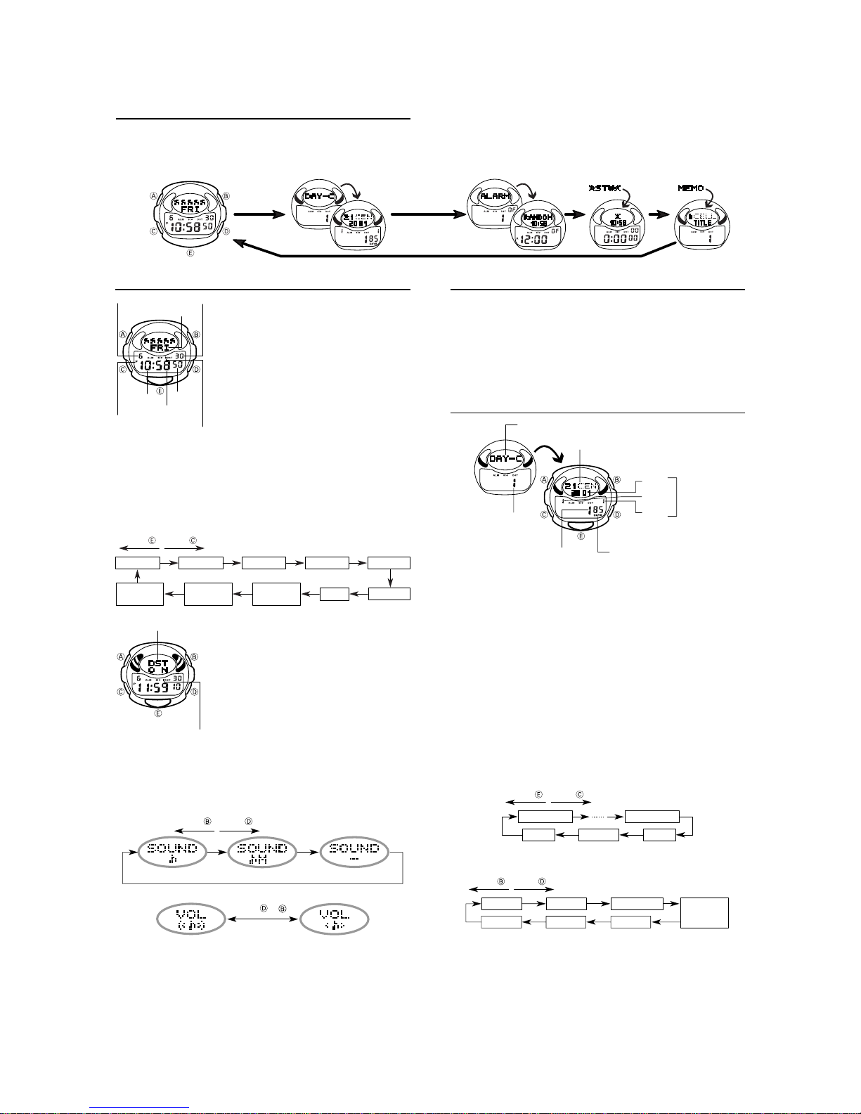
2. OPERATION CHART: QW-2489
General Guide
CC
• Press
C to change from mode to mode.
CC
EE
• Pressing
E in any mode besides the Alarm Mode illuminates to the display for
EE
about three seconds. The backlight is disabled while a setting screen is on
the display.
Timekeeping Mode Day Counter Mode
CC
Press
C.
CC
• If you do not perform any operation for a few minutes while a setting screen (with
flashing digits) is on the display , the w atch automatically e xits the setting screen.
• If you do not perform any operation for a few minutes in any mode besides
stopwatch mode, the watch automatically reverts to the normal timekeeping
screen.
Alarm Mode Stopwatch Mode
Memo Mode
Timekeeping Mode
DD
Press
D to toggle between 12-hour and 24-hour
Month
Day of week
Hour
PM indicator
Timekeeping Mode Settings
In addition to settings for the current time and date, the Timekeeping Mode
setting screen also lets you turn button tones and melody play on and off,
adjust tones and melody volume, and adjust display contrast.
To make Timekeeping Mode settings
1.While in the Timekeeping Mode, hold down
on the display, indicating the setting screen.
CC
2.Press
C to move the flashing in the sequence shown below . Press
CC
the flashing in the opposite direction.
Press . Press .
Seconds DST Hour Minutes Year
Contrast
(CNT)
DST indicator 1
* Daylight Saving Time (DST), which is also sometimes called “summer time”
advances the time for one hour, as is the custom in some areas during the
summer. Remember that not all countries or even local areas use Daylight
Saving Time.
• While the SOUND (button tones) setting is selected, press
beep and musical tone on and off, as shown below.
• Changing the SOUND also changes the Hourly Time Signal tones.
Day
Seconds
Minutes
DST indicator 2
DST indicator 2
Press . Press .
Beep
• While the VOL setting is selected, press
• With some models, changing the volume setting affects volume very little.
• While the CNT setting is selected, press
make it lighter.
• While any other setting is selected (flashing), press
decrease it. Holding down either button changes the setting at high speed.
4.After you make the settings you want, press
• The day of the week is automatically set in accordance with the date.
• The date can be set within the range of J an uary 1, 2000 to December 31, 2039.
• The watch's built-in full automatic calendar automatically makes allowances
for different month lengths and leap years.
Once you set the date, there should be no reason to change it except after
the replacement of the watch's battery.
Loud
DD
timekeeping.
• With 12-hour timekeeping, times between midnight
and noon are indicated by A (am), while times
between noon and midnight are indicated by P
(pm).
• The A and P indicators do not appear for 24-hour
timekeeping.
BB
• Pressing
B plays a randomly selected melody . T o
BB
stop a playing melody , press any b utton besides
EE
• Pressing
E while a melody is playing toggles the
EE
display between an animated character and the
name of the melody.
EE
• Press
E to illuminate the display for about three
EE
seconds. When 12-hour timekeeping is being used,
EE
pressing
E also displays an animated character.
EE
AA
A until the second’s digits flash
AA
Volume
(VOL)
3.While the second’s setting is selected (flashing),
• If you press
the range of 30 to 59, the seconds are reset to 00
and 1 is added to the minutes. If the second’s
setting is in the range of 00 to 29, the minute’s
count is unchanged.
• While the DST (Daylight Saving Time) setting is
selected, press
• DST indicator 1 is displayed in the Timekeeping
Mode setting screen only when the DST setting is
selected. It shows ON when the DST setting is on,
and OFF when the DST setting is off.
• DST indicator 2 is displayed in the Timekeeping
Mode, Day Counter Mode and Alarm Mode when
the DST setting is turned on.
press
D or
Musical tone
Press or .
Sound
(SOUND)
DD
BB
B to reset it to 00.
DD
BB
DD
BB
D or
B while the second’s setting is in
DD
BB
DD
BB
D or
B to toggle it on and off.
DD
BB
DD
BB
D or
B to toggle it between loud and soft.
DD
BB
DD
D to make the display darker , or
DD
DD
D to increase it or
DD
AA
A to exit the setting screen.
AA
Soft
DD
D or
DD
Off
BB
B to turn the
BB
EE
E to move
EE
MonthDay
BB
B to
BB
BB
B to
BB
EE
E.
EE
About the Backlight
EE
Pressing
E in any mode besides the Alarm Mode illuminates the display for
EE
about three seconds. The backlight is disabled while a setting screen is on the
display.
• The backlight of this watch employs an electro-luminescent (EL) light, which
loses its illumination power after very long term use.
• Frequent use of the backlight shortens battery life.
• The illumination provided by the backlight may be hard to see when viewed
under direct sunlight.
• The backlight automatically turns off an alarm sounds.
• The watch emits an audible sound whenever the display is illuminated. This
does not indicate malfunction.
Day Counter Mode
Mode indicator
Text
Year
Month
Day counter
record number
The Day Counter Mode lets you count the number of days from the
Timekeeping Mode’s current date to a specific target date.
• There are five Day Counter records, each of which can be assigned up to 12
characters of text and a target date.
• When a target date is reached, the DAYS indicator flashes on the display in
the Timekeeping Mode. The DA YS indicator also flashes in the Day Counter
Mode when the screen for the target date is on the display.
• The DAYS indicator flashes on the target date each year, regardless of the
year setting of the target date.
• The initial default date for a Day Counter record is 2001/1/1, and the text area
contains All spaces. (All spaces for the text display a series of hyphens “ – – –
– – ”.)
Recalling Day Counter Data
In the Day Counter Mode, press
screens.
• The day count is a negative value whenever the target date comes before the
current date.
To set the target date
1.In the Day Counter Mode, press
set.
2.Hold down
display. This indicates the input screen.
3.Press
the flashing in the opposite direction.
4.While the flashing is located within the text area, use
characters at the current location of the flashing. Holding down either button
scrolls through characters at high speed.
Number of days
DD
D to scroll through the Day Counter record
DD
DD
D to display a record number you want to
DD
AA
A until the first (leftmost) text character starts to flash on the
AA
CC
C to move the flashing in the sequence shown below . Press
CC
Press . Press .
Character 1
Day
Press . Press .
Space A to Z Punctuation
Hyphen Symbols
Month
Numbers
Day
DAYS indicator
Character 12
Year
DD
D or
DD
See the “CHARACTER LIST” at the back of this manual for details.
5.While any other setting is selected, press
Holding down either button changes the setting at high speed.
DD
• Pressing
area clears any input text and resets the date setting to the current date. At
this time the message “CLEAR” appears on the display.
• Pressing
date area resets the date setting to the current date without affecting the text.
6.After you make the settings you want, press
• The date can be set within the range of January 1, 1940 to December 31,
2039.
BB
D and
B at the same time while the flashing is located within the text
DD
BB
DD
BB
D and
B at the same time while the flashing is located within the
DD
BB
DD
D to increase it or
DD
AA
A to exit the input screen.
AA
— 2 —
Target Date
EE
E to move
EE
BB
B to scroll through
BB
Japanese
characters
BB
B to decrease it.
BB
Page 5

Alarm Mode
Mode indicator
Melody name
Current time
Stopwatch Mode
Mode indicator
Current time
The stopwatch Mode lets you measure elapsed time,
split times, and two finishes. The range of the
stopwatch is 23 hours, 59 minutes, 59.99 seconds.
Y ou can use the EL bac klight b y pressing
time while the stopwatch is operating.
EE
E at any
EE
Alarm number
You can set up to five melody alarms. When a Daily Alarm is turned on, its
melody alarm sounds for about 20 seconds at the preset time each day. In the
Timekeeping Mode, press any button (except
it starts to sound. Pressing
between an animated character and the name of the melody that is playing.
When the Hourly Time Signal is turned on, the watch beeps every hour on the
hour.
To set the alarm time
1.While in the alarm Mode, press
set.
Alarm 1 Alarm 5Alarm 2 Alarm 3 Alarm 4
2.Hold down
3.Press
AA
A until the melody setting starts to flash on the display , indicating
AA
the setting screen. The alarm is automatically turned on at this time.
CC
C to change the selection in the sequence shown below.
CC
Melody Setting Hour Minutes
Hour
EE
E while a melody is playing toggles the display
EE
DD
D to display the alarm number you want to
DD
SIG: 00 (Hourly Time Signal)
4.While melody setting is selected, use
Setting Alarm Sound
– 0
Press .
Press .
See the “MELODY LIST” at the back of this manual for the names of
melodies.
Some melody alarms tune names may be displayed in abbreviated format.
• While any other setting is selected, press
Holding down either button changes the setting at high speed.
5.After you make the settings you want, press
• The format (12-hour and 24-hour) of the alarm time matches the format you
select for normal timekeeping.
• When setting the alarm time using the 12-hour format, take care to set the
time correctly as morning or afternoon.
To stop a melody alarm
• Press an y b utton (except
To turn a daily Alarm or the Hourly Time Signal on and off
DD
1.Use
D to display the alarm you want to turn on or off, or the screen for
DD
turning the Hourly Time Signal on or off.
2.Press
Alarm indicator 1
Alarm indicator 3
Alarm indicator 2
Hourly Time Signal
indicator 1
Hourly Time Signal
indicator 3
Hourly Time Signal
indicator 2
– 1
– 2
– 3
– 4
– 5
–
BB
B to toggle the displayed alarm or Hourly Time Signal on and off.
BB
Ramdom play of melodies 1, 2, 3, 4 and 5
Melody 1
Melody 2
Melody 3
Melody 4
Melody 5
Beeper
EE
E) to stop a melody alarm after it starts to sound.
EE
• Alarm indicator 1 is displayed in the alarm mode
only. It indicates the on/off status of the currently
displayed alarm only. Note that this indicator is
used for different purposes in other modes.
• Alarm indicator 2 is displayed in all modes when
any of the five alarms is turned on.
• Alarm indicator 3 is displayed in the Alarm Mode
only. It shows on when the currently displayed
alarm is on, and OF when the currently displayed
alarm is off.
• Hourly Time Signal indicator 1 is displayed in the
Alarm Mode only when the Hourly Time Signal is
turned on. Note that this indicator is used for
different purposes in other modes.
• Hourly Time Signal indicator 2 is displayed in all
modes when the Hourly Time Signal is turned on.
• Hourly Time Signal indicator 3 is displayed in the
Alarm Mode only. It shows on when the Hourly
Time Signal is on, and OF when the Hourly Time
Signal is off.
To test the alarm
In the Alarm Mode, display the alarm you want to
sound, and then press
Y ou can also press
setting the alarm time.
• To stop a playing melody or beep, press any button.
Minutes
EE
E) to stop the melody alarm after
EE
DD
BB
D or
B to scroll through melody names.
DD
BB
DD
D to increase it or
DD
AA
A to exit the setting screen.
AA
EE
E to play its melody or beep.
EE
EE
E to play an alarm’s melody while
EE
BB
B to decrease it.
BB
Hours
Minutes
Seconds
1/100 second
Elapsed time measurement
Start
Split time measurement
Start
Split time and 1st-2nd place times
Start
Stop Re-start Stop Clear
Split Split release Stop Clear
Split Stop Split release Clear
First runner
finishes.
Second runner
finishes.
Record time of
first runner.
Record time of
second runner.
Memo Mode
Mode indicator
Title
Memo number
To input a memo
1.In the Memo Mode, press
2.Hold down
3.Press
4. Use
AA
A until the first (leftmost) character of the memo title starts to
AA
flash on the display. This indicates the input screen.
CC
C to move the flashing in the sequence shown below . Press
CC
the flashing in the opposite direction.
Press . Press .
Title Character 1
Data Character 16
DD
BB
D or
B to scroll through characters at the current location of the flashing.
DD
BB
Holding down either button scrolls at high speed.
Press . Press .
Space A to Z Punctuation
Hyphen Symbols
See the “CHARACTER LIST” at the back of this manual for details.
DD
• Pressing
D and
DD
all title and data. At this time the message “CLEAR” appears on the display.
5. After you input the data you want, press
The Memo Mode lets you store up to five memos,
each with an eight-character title and 16 characters
of data.
Recalling a Memo
In the Memo Mode, press
Memo titles. When you find the title you want, press
BB
B, and the screen alternates between the title and
BB
data.
• The display can show only five characters at a time.
Longer text scrolls continuously from right to left.
The symbol “
to the left is the last, and the character or digit to
the right is the first.
• A series of hyphens “ – – – – – ” is displayed for a
memo that does not contain any data.
DD
D to display the memo number you want to set.
DD
Numbers
BB
B at the same time while inputting memo title or data clears
BB
DD
D to scroll through the
DD
” indicates that the character or digit
EE
E to move
EE
Title Character 8
Data Character 1
Japanese
characters
AA
A to exit the input screen.
AA
— 3 —
Page 6

3. DRAWINGS: QW-2489
3-1. LCD DIAGRAM
PM
AM
K0
K1
K2
LC1
K3
L17
L16
L 3
L 4
L 5
L 6
L 7
L 8
L 9
L10
L11
L12
L15
L13
L14
L19
L20
L22
L18
L21
K4
Y12
L25
L24
L23
L27
L26
LC2
L28
K9
K8
K7
K6
K5
Y0
X0
a8
f8
e5
b8
g8
e8
c8
d8
e4
a4
f4
b4
g4
c4
d4
a5
f5
b5
g5
c5
d5
COL
SIG DSTALM
a2
f2
g2
e2
d2
e3
a3
f3
b3
g3
c3
d3
b9
c9
c2
b2
X28
a7
f7
g7
e7
d7
a1
f1
b1
g1
e1
c1
d1
a6
f6
b7
c7
b6
g6
e6
c6
d6
a0
f0
b0
g0
e0
c0
d0
DAYS
SEG.
L3
L4
L5
L6
L7
L8
L9
L10
L11
L12
L13
L14
L15
L16
L17
L18
L19
L20
L21
L22
L23
L24
L25
L26
COM.
L C 1
c9
e8
g8
c8
X6Y12
X7Y12
X8Y12
X9Y12
X10Y12
X11Y12
X12Y12
X13Y12
X14Y12
X15Y12
X16Y12
X17Y12
X18Y12
X19Y12
X20Y12
X21Y12
X22Y12
L C 2
d8
X6Y11
X7Y11
X8Y11
X9Y11
X10Y11
X11Y11
X12Y11
X13Y11
X14Y11
X15Y11
X16Y11
X17Y11
X18Y11
X19Y11
X20Y11
X21Y11
X22Y11
LC8
L C 3
K2
X0Y8
X1Y8
X2Y8
X3Y8
X4Y8
X5Y8
X6Y8
X7Y8
X8Y8
X9Y8
X10Y8
X11Y8
X12Y8
X13Y8
X14Y8
X15Y8
X16Y8
X17Y8
X18Y8
X19Y8
X20Y8
X21Y8
X22Y8
LC7
LC6
L C 4
K3
X0Y9
X1Y9
X2Y9
X3Y9
X4Y9
X5Y9
X6Y9
X7Y9
X8Y9
X9Y9
X10Y9
X11Y9
X12Y9
X13Y9
X14Y9
X15Y9
X16Y9
X17Y9
X18Y9
X19Y9
X20Y9
X21Y9
X22Y9
L50
L49
L48
L C 5
K4
X0Y10
X1Y10
X2Y10
X3Y10
X4Y10
X5Y10
X6Y10
X7Y10
X8Y10
X9Y10
X10Y10
X11Y10
X12Y10
X13Y10
X14Y10
X15Y10
X16Y10
X17Y10
X18Y10
X19Y10
X20Y10
X21Y10
X22Y10
L47
L46
L C 6
b9
f8
a8
b8
X6Y5
X7Y5
X8Y5
X9Y5
X10Y5
X11Y5
X12Y5
X13Y5
X14Y5
X15Y5
X16Y5
X17Y5
X18Y5
X19Y5
X20Y5
X21Y5
X22Y5
L45
L44
L C 7
K0
X0Y6
X1Y6
X2Y6
X3Y6
X4Y6
X5Y6
X6Y6
X7Y6
X8Y6
X9Y6
X10Y6
X11Y6
X12Y6
X13Y6
X14Y6
X15Y6
X16Y6
X17Y6
X18Y6
X19Y6
X20Y6
X21Y6
X22Y6
L36
L34
L35
L37
L38
L39
L40
L41
L42
L43
L C 8
K1
X0Y7
X1Y7
X2Y7
X3Y7
X4Y7
X5Y7
X6Y7
X7Y7
X8Y7
X9Y7
X10Y7
X11Y7
X12Y7
X13Y7
X14Y7
X15Y7
X16Y7
X17Y7
X18Y7
X19Y7
X20Y7
X21Y7
X22Y7
SEG.
L27
L28
L29
L30
L31
L32
L33
L34
L35
L36
L37
L38
L39
L40
L41
L42
L43
L44
L45
L46
L47
L48
L49
L50
COM.
L C 1
e7
g7
c7
e6
g6
c6
X22Y3
X21Y3
X20Y3
X19Y3
X18Y3
X17Y3
X16Y3
X15Y3
X14Y3
X13Y3
X12Y3
X11Y3
X10Y3
X9Y3
X8Y3
X7Y3
X6Y3
L C 2
d7
d6
X22Y2
X21Y2
X20Y2
X19Y2
X18Y2
X17Y2
X16Y2
X15Y2
X14Y2
X13Y2
X12Y2
X11Y2
X10Y2
X9Y2
X8Y2
X7Y2
X6Y2
L33
L C 3
X23Y8
X24Y8
X25Y8
X26Y8
X27Y8
X28Y8
K7
b0
a0
f0
b1
a1
b2
a2
DST
a3
SIG
ALM
b4
a4
a5
f5
PM
L31
L32
X23Y9
X24Y9
X25Y9
X26Y9
X27Y9
X28Y9
L30
LC 4
K8
c0
g0
c1
g1
f1
c2
g2
f2
b3
g3
f3
COL
g4
f4
b5
g5
AM
L29
X23Y10
X24Y10
X25Y10
X26Y10
X27Y10
X28Y10
DAYS
LC5
L C 5
K9
d0
e0
d1
e1
d2
e2
c3
d3
e3
c4
d4
e4
c5
d5
e5
LC4
LC3
L C 6
f7
a7
b7
f6
a6
b6
X22Y4
X21Y4
X20Y4
X19Y4
X18Y4
X17Y4
X16Y4
X15Y4
X14Y4
X13Y4
X12Y4
X11Y4
X10Y4
X9Y4
X8Y4
X7Y4
X6Y4
L C 7
X23Y6
X24Y6
X25Y6
X26Y6
X27Y6
X28Y6
K5
X22Y1
X21Y1
X20Y1
X19Y1
X18Y1
X17Y1
X16Y1
X15Y1
X14Y1
X13Y1
X12Y1
X11Y1
X10Y1
X9Y1
X8Y1
X7Y1
X6Y1
L C 8
X23Y7
X24Y7
X25Y7
X26Y7
X27Y7
X28Y7
K6
X22Y0
X21Y0
X20Y0
X19Y0
X18Y0
X17Y0
X16Y0
X15Y0
X14Y0
X13Y0
X12Y0
X11Y0
X10Y0
X9Y0
X8Y0
X7Y0
X6Y0
— 4 —
Page 7

3-2. CIRCUIT DIAGRAM
LCD
VCC
WPWPSCL
SDA
Vss A2 A1 A0
EEPROM
Vcc
SCL
LL2
Di2
PZ
SDA
R2
C12
Tr1
Xtal
CT
C9
+
BACK
FRONT
L3 L50 LC1 LC8
XTB
L1 , L2 * 1
XT
L51 ~ L52 * 1
AC
T1
T2
T3
VREF1
GNDA
VREF
C11
VDD2A
LD1*1 VDD2 GND VCH VDSP VDD1 VC1 VC2 VHF VC3 VC4VDD3
+
BAT
C6
EL
LL1
C5
GND
L-
VOUT
L+
SDI*1
CSB*1
TOTAL 107 PINS
BONDING 97 PINS
Display 60
Others 47
C4
E'
CLF2
INV
CLF1
V+
LD2*1
EMP*1
LSI
C3
C10
BD1 BD2 MIN
C1
C2
ENV SDOSCK SCUT
C8
KI1
KI2
KI3
KI4
KI5
KI8
KC5*1
KI9
KC4
KC3
KC2
KI7
KI6
KC1
C7
✽ 1. No bonding
S1
S2
S3
S4
F0
— 5 —
Page 8

3-3. CHECKING TERMINALS AND COMPONENT
7. Cushion/6
(7211 0064)
4. Oscillator/Crystal
Xtal
(1004 1131)
KI2
ELD
KI3
Tr1
Di2
Diode
PCB WITH LSI
CLF1
KI5
Transistor
Memory/
External
XTB
XT
GND
CLF2
CT 3.
Capacitor/Trimmer
(1001 0950)
KI9
GND
KI6
KC4
KC3
KI6
KC2
KI7 KC2 KI6
Capacitor/Chip
C11
C4 Capacitor/Chip
C9 Capacitor/Chip
GND
BD2
KI4
BD2
BD1
A4
BD1
VDD2
KI1
VCC
WP
XT
KI4
VCC
VDD2
SCUT
VCC
SCK
SDO
WP
VCC
WP
GND
GND
GND
GND
GND
VCC
KI1
BD1
C2 Capacitor/Chip
VREF
VREF
GND
GND
GND
SCK
BD2
VDD2
GND
VC3
GND
VC4
VDD2
CLF1
L
CLF2
KC1
L
VDD2
C3 Capacitor/Chip
GND
VDD2
VC1
VC3
VCH
VHF
VC1
L+
VC2
GND
L-
KI5
VDSP
VDSP
GND
VCH
AC
GND
SDO
KI2
VDD1
VDD3
GND
GND
KI3
L+
ELD
LGND
GND
GND
C10
Capacitor/Chip
R2
Resistor/Chip
6. Cushion/506
(7211 9631)
CoilLL2
INV
6. Cushion/506
(7211 9631)
Inverter
C8 Capacitor/
C5
Capacitor/
Tantalum
Capacitor/Chip
C12
C7 Capacitor/Chip
Capacitor/Tantalum
C6
C1 Capacitor/Chip
LL1
Coil
Top view of P.C.B. ass'y Bottom view of P.C.B. ass'y
Chip
— 6 —
Page 9

4. EXPLODED VIEW: QW-2489
12 (7233 2732)
14 (7230 0616)
1 (1005 8548)
2a (7020 6080)
2b (7020 6086)
2c (7020 6081)
9 (1002 1815)
PCB (Unrepairable)
13 (7230 0623)
Battery/Lithium
(CR1620)
5 (1002 7903)
11 (7233 2629)
8 (7231 1885)
10 (7229 0790)
— 7 —
Page 10

5. PARTS LIST: QW-2489
-
-
-
p
p
Note: 1. Prices and specifications are subject to change without prior notice.
2. Spare parts are classified as follows according to their importance in after-sales service.
A Rank -----------------------------------B Rank -----------------------------------C Rank ------------------------------------
3. Batteries in Bulk pack on the tray will be supplied from our Overseas Spare Parts Section under charge basis.
Batteries in Blister pack will be supplied from our Sales Department.
4. As for order/supply of spare parts, refer to the separate publication "GUIDE BOOK for spare parts supply".
Very Important
Important
Less important
Item Code No. Parts Name S
7640 5044 MODULE QW-2489YC-01TK BGM-221V-3 1 A
7640 5045 MODULE QW-2489YC-02TK BGM-221V-8 1 A
7640 5046 MODULE QW-2489YC-03TK BGM-221DM-1/2 1 A
1 1005 8548 LCD S2252-01THP QW-2489YC Common 1 A
2a 7020 6080 EL YEL-1564-A-01 QW-2489YC-01TK 1 A
2b 7020 6086 EL YEL-1564-A-63 QW-2489YC-02TK 1 A
2c 7020 6081 EL YEL-1564-A-03 QW-2489YC-03TK 1 A
3 1001 0950 CAPACITOR/TRIMMER CTZ2E-30C-W2-P QW-2489YC Common 1 B
4 1004 1131 OSCILLATOR/CRYSTAL DT-26SJ(T) QW-2489YC Common 1 B
5 1002 7903 CONTACT/BATTERY(-) Q39603B-1 QW-2489YC Common 1 C
6 7211 9631 CUSHION/506 Q49364-1 QW-2489YC Common 2 C
7 7211 0064 CUSHION/6 Q4914-1 QW-2489YC Common 1 C
8 7231 1885 HOLDER/BATTERY Q360562-1 QW-2489YC Common 1 C
9 1002 1815 INTERCONNECTOR Q461567A-1 QW-2489YC Common 2 C
10 7229 0790 LABEL/1856 Q461569-1 QW-2489YC Common 1 C
11 7233 2629 SHEET/INSULATION Q461568-1 QW-2489YC Common 1 C
12 7233 2732 SPACER Q461570-1 QW-2489YC Common 1 C
13 7230 0623 SPRING/COIL 1416-1 Q451200-1 QW-2489YC Common 2 B
14 7230 0616 SPRING/COIL 1199-1 Q437728B-1 QW-2489YC Common 2 B
7111 5056 BATTERY/LITHIUM CR1620 QW-2489YC Common 1
For the
rices and minimum order/supply quantities of the above parts, refer to the Parts Price List P.P.L.-577.
ecification Applicable Q R
Notes: Q - Used quantity
R - Rank
— 8 —
Page 11

6. PRECAUTIONS FOR REPAIR: QW-2489
6-1. AC (ALL CLEAR) AND REMOVING OF MODULE
1. Perform AC (ALL CLEAR) when inserting a new battery, or else the memories and/ or counters may give
erratic displays.
Touch the AC contact and the negative (–) side of the main plate with the metallic tweezers.
The contact should be made for about two seconds.
2. On removing of the module from the case, please insert the precision screw driver between the module
and the case pointed by an arrow.
Metallic tweezers
AC
6-2. ACCURACY CHECKING
Check the accuracy of the module with the quartz timer after switching the module to “ACCURACY
CHECKING MODE”.
The operations are shown below:
A) SWITCHING TO “ACCURACY CHECKING MODE”
While pressing D button, press A and C buttons at the normal time keeping mode.
Then all the segments are displayed and the LCD drive signals are changed to the static drive signal
of “32 Hz” so that you can check the accuracy with the quartz timer.
B) CANCELLATION OF THE “ACCURACY CHECKING MODE”
Push any button except for D button.
Then the display is returned to its original state.
NOTE: The “ACCURACY CHECKING MODE” will automatically return
to the regular mode in 1 ~ 2 hour(s) without any operation.
QW-2489
— 9 —
Page 12

CASIO TECHNO CO.,LTD.
Overseas Service Division
Nishi-Shinjuku Kimuraya Bldg. 1F
5-25, Nishi-Shinjuku 7-Chome
Shinjuku-ku, Tokyo 160-0023, Japan
 Loading...