

Page 1

SERVICE MANUAL
& PARTS LIST
REF. NO. S/M-748
AUG. 2001
MODULE NO.
QW-2387
G-200
R
(WITHOUT PRICE)
Page 2

CONTENTS
Page
1. SPECIFICATIONS: QW-2387........................................................................ 1
2. OPERATION CHART: QW-2387................................................................... 2
3. DRAWINGS: QW-2387
3-1. LCD DIAGRAM ................................................................................................. 4
3-2. CIRCUIT DIAGRAM .......................................................................................... 5
3-3. CHECKING TERMINALS AND COMPONENTS .............................................. 6
4. EXPLODED VIEW: QW-2387........................................................................ 7
5. PARTS LIST: QW-2387................................................................................. 8
6. EXPLODED VIEW: ANALOG BLOCK OF QW-2387 ................................... 9
7. PARTS LIST: ANALOG BLOCK OF QW-2387 .......................................... 10
8. PRECAUTIONS FOR REPAIR: QW-2387
8-1. AC (ALL CLEAR) AND REMOVING OF MODULE ........................................ 11
8-2. ACCURACY CHECKING ................................................................................ 11
Page 3

1. SPECIFICATIONS: QW-2387
Item Detail
Battery CR2016
Battery life Approx. 3 years
Current consumption 1.13 µA maximum
Alarm system Piezo plate on Back cover
Accuracy ±15 sec./month
Accuracy setting system Trimer capacitor
Accuracy checking See page 11
Functions: • Shock resistant (G-SHOCK)
• "ANTIMAGNETIC" watch (ISO)*
• LED light
• Dual time
• 1/100-sec stopwatch
Measuring capacity: 23:59'59.99"
Measuring unit: 1/100-sec (for the first 60 min)
1-sec (after 60 min)
Measuring mode: Elapsed time
• Daily alarm
• Auto-calendar ( to year 2039)
• 12/24-hour formats
• Regular timekeeping
Analog: 2 hands (Hr, min)
Digital: Hr, min, sec, pm, month, date, day
*Though this watch is designed to withstand exposure to magnetic force,
you should still keep it away from machinery and appliances that generate a strong magnetic field.
Exposure to strong magnetism can cause timekeeping to slow, affecting
timekeeping accuracy.
— 1 —
Page 4
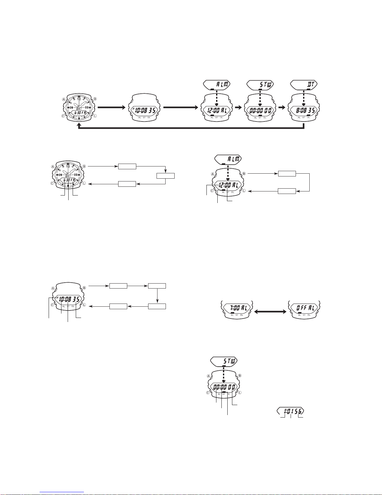
2. OPERATION CHART: QW-2387
•Press C to change from mode to mode.
•In any mode (except when making any settings), press L to illuminate the display.
Calendar Mode
Press C.
Timekeeping Mode
CALENDAR MODE
GENERAL GUIDE
To set the date
Month
Day
1.In the Calendar Mode, hold down B for about two seconds, until “ADJ” and then
the year digits flash on the display. Keep B depressed until the year digits flash.
2.While any setting is selected (flashing), press C to increase it. Holding down C
changes the flashing setting at high speed.
3.Press B to move the selection around the display in the above sequence.
• The day of the week is automatically set in accordance with the date.
• The date can be set with the range of January 1,1995 to December 31, 2039.
• If you do not operate any button for a few minutes while a selection is flashing, the
flashing stops and the watch goes back to the Calendar Mode automatically.
Hold down B. Press B.
Press B.
Day of week
Year
Day
Month
Press B.
TIMEKEEPING MODE
The minutes hand advances 1/3 of a minute each time the second’s count in the
digital display reaches 00, 20 and 40 seconds.
To set the digital time
Hold down B.
Hour
PM indicator
1. In the Timekeeping Mode, hold down B for about two seconds, until “ADJ” and
then the second’s digits flash on the display. Keep B depressed until the second’s
digits flash.
2.While the second’s digits are selected (flashing), press C to reset the seconds to
00. If you press C while the second’s count is in the range of 30 to 59, the seconds are reset to 00 and 1 is added to the minutes. If the second’s count is in the
range of 00 to 29, the minute’s count is unchanged.
3.Press B to move the selection around the display in the above sequence.
4. While hour or minutes are selected (flashing), press C to increase the setting.
Holding down C changes the current setting at high speed. While the 12/24-hour
setting is selected, press C to switch between the two formats.
•If you do not operate any button for a few minutes while a selection is flashing, the
flashing stops and the watch goes back to the Timekeeping Mode automatically.
Hand setting
Each press of A advances the hands 20 seconds. Holding down A advances the
hands at high speed.
•Note that the hands can be advanced only and cannot be moved back. Take care
so you do not go past the setting you want to make.
Seconds
Minutes
Seconds
Press B.
12/24
Press B.
Press B.
Hour
Press B.
Minutes
ABOUT THE BACKLIGHT
In any mode (except when making any settings), press L to illuminate the display
for about two seconds.
•The backlight of this watch illuminates both the digital display and analog face.
•The illumination provided by the backlight may be hard to see when viewed under
direct sunlight.
•The backlight automatically stops illuminating whenever an alarm sounds.
•Frequent use of the backlight shortens battery life.
Alarm Mode
Stopwatch Mode Dual Time Mode
ALARM MODE
Hold down B.
Hour
Mode indicator
When an alarm is turned on, an alarm tone sounds for 20 seconds at the preset time
each day.
To set the alarm time
1.In the Alarm Mode, hold down B for about two seconds, until “ADJ” and then the
hour digits flash on the display. Keep B depressed until the hour digits flash.
2.Press C to increase the setting. Holding down C changes the current setting at
high speed.
3.Press B to change the selection in the above sequence.
• The format (12-hour and 24-hour) of the alarm time matches the format you select
for normal timekeeping.
• When setting the alarm time using the 12-hour format, take care to set the time
correctly as morning or afternoon.
• If you do not operate any button for a few minutes while a selection is flashing, the
flashing stops and the watch goes back to the Alarm Mode automatically.
• The alarm is turned on automatically whenever you change the alarm time setting.
To stop the alarm
Press any button to stop the alarm after it starts to sound.
To switch the daily alarm on and off
In the Alarm Mode, press B to turn the daily alarm on and off.
To test the alarm
Hold down C while in any mode to sound the alarm.
Minutes
ON
Press B.
Press
Hour
Press B.
Minutes
OFF
B.
STOPWATCH MODE
The Stopwatch Mode lets you measure elapsed time. The
range of the stopwatch is 23 hours, 59 minutes 59 seconds. The measuring unit for the first hour of elapsed
time measurement is 1/100-second. After that the unit is
one second.
To measure elapsed time
1.Press B to start the stopwatch.
2.Press B again to stop the stopwatch.
• You can repeat steps 1 and 2 as many times as you
want.
Minutes
Seconds
Mode indicator
3.To reset the stopwatch time to all zeros, hold down B.
1/100 seconds
After the first hour
Hour
Minutes
Seconds
— 2 —
Page 5
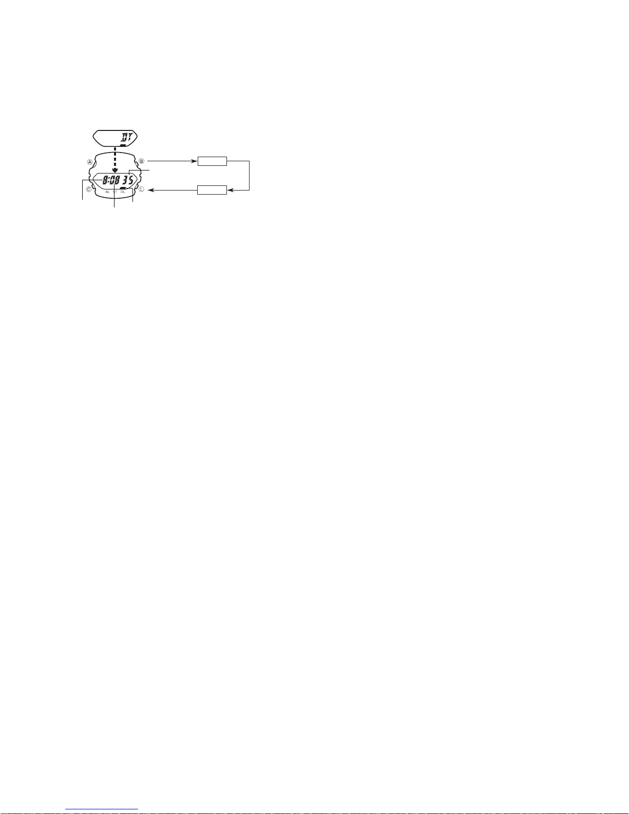
The Dual Time Mode lets you keep track of the time in another time zone.
DUAL TIME MODE
To set the Dual Time
Hold down B.
Seconds
Hour
1.In the Dual Time Mode, hold down B for about two seconds, until “ADJ” and then
the hour digits flash on the display. Keep B depressed until the hour digits flash.
2.Press C to increase the setting. Holding down C changes the current setting at
high speed.
3.Press B to move the selection around the display in the above sequence.
• The format (12-hour and 24-hour) of the Dual Time matches the format you select
for normal timekeeping.
• The second’s count is synchronized with the second’s count in the Timekeeping
Mode.
• If you do not operate any button for a few minutes while a selection is flashing, the
flashing stops and the watch goes back to the Dual Time Mode automatically.
Minutes
Mode indicator
Press B.
Hour
Press B.
Minutes
— 3 —
Page 6

3. DRAWINGS: QW-2387
3-1. LCD DIAGRAM
P
a5
f5
g5
e5
c5
d5
L27
L26
b5
SEG.
L25
e4
d4
L12
a4
col1
b4
f4
g4
hyp
c4
col0
AL1
L24
L23
L22
COM.
LC1
(DT0)
L13
L14
L15
L16
L17
L18
L19
L20
L21
DT1
ST1
L22
L23
L24
L25
L26
L27
(k2)
a3
f3
g3
e3
c3
d3
L21
L20
L19
LC2
(ST0)
c0
d0
i0
b0
g0
e0
k0
c1
d1
i1
b1
g1
e1
L18
a2
b3
ST1
L17
b2
f2
g2
e2
c2
d2
L16
L15
L14
i1
L13
LC3
(AL0)
(i3)
a0
f0
j0
d3
a1
f1
d5
d2
e2
k1
c2
g2
(j2)
j1
b2
a2
f2
d4
(h2)
j1
k1
DT1
LC4
hyp
col1
(j3)
(h3)
a3
b3
P
f5
a5
b5
f4
a4
b4
a1
h1
f1
g1
e1
d1
L12
LC5
c1
LC4
h0 a0
b1
j0
k0
i0
LC3
LC2
b0
f0
g0
e0
c0
d0
LC1
LC5
col0
(k3)
e3
h0
f3
g3
c3
h1
AL1
e5
g5
c5
e4
g4
c4
— 4 —
Page 7

3-2. CIRCUIT DIAGRAM
LCD
CT
Xtal
LC1 - - - - LC5
T1
AC
XTB
XT
N1
N2
N3
N4
LD2
VSS2
C5
BAT
+
Tr2
LED1
R1 R2 R3
L12 - - - L27,
LSI
TOTAL 68PINS
BONDING 51PINS
VDD
LED2
VSS1
VCH VSS3 VC1 VC2
C2
C3C4
Open (No Soldering)
✽1
Terminal L
✽2
No bonding
✽3
Short (Soldering)
✽4
Not used
✽5
L1 - - L11 28 - - 31
C1
✽3
✽2
PZ
BD
✽3
✽3
Tr1
O1
O2
T2
VPM
LD1
LD3
LD4
KI5
KI6
KI1
KI2
KI3
KI4
KI7
KI8
LL1
✽5
An.B
✽1
✽4
S1
S2
S3
S4
✽5
— 5 —
Page 8

3-3. CHECKING TERMINALS AND COMPONENTS
Resistor/Chip
R2
Resistor/Chip
R3
Resistor/Chip
R1
Tr1
Transistor
9. Cushion/506
(7211 9631)
5.Oscillator/Crystal
Xtal
(7110 0693)
CT
4. Capacitor/Trimmer
(1001 0950)
KI2
KI3
LED2
ANO3
CATH
LED
VDD VDD
ANO2
ANO3
VDD
ANO1
VDD VDD
KI8
VDD VDD
VDD VDD
N1 N2
N3 N4
3a.PCB ass'y
(7640 4665)
VDD
KI7 KI6
ANO2CATHANO1
O1
KI1
KI4KI4
KI5
KI5 LD1
L
L
KI1
VDD
VCH
O2
KI5
LD1
CATH
ANO4
Capacitor/Chip
C1
L
L
VDD
VSS2
BD
VDD
VDD
LD1
LD2
VC1
KI4 O2 O1
VSS2
ANO4
VC1
VC2
LD2
CATH
VDD
VSS2
VSS3
VDD
VDD
VDD
VDD
VCH
VSS2
VDD
VSS1
CATH
KI2
VSS2
VSS2
XTB
XT
AC
10. Cushion/6
KI2
VDD
XT
KI3
(7211 0064)
Transistor
Tr2
Coil
LL1
Top view of P.C.B. ass’y
C3
Capacitor/Tantalum
C5
— 6 —
Capacitor/Chip
Capacitor/Chip
C2
Capacitor/Chip
C4
Bottom view of P.C.B. ass’y
Page 9

4. EXPLODED VIEW: QW-2387
13 (1005 3617)
2 (1005 3616)
19 (7224 0652)
11 (7231 1962)
16 (1005 3615)
12 (1005 3621)
18 (7229 0772)
8 (7218 0438)
20 (1005 3614)
6 (7640 4662)
16 (1005 3615)
1 (1003 6046)
14 (1005 3618)
3a (7640 4665)
3b (7640 4728)
PCB ass'y
7 (1002 7903)
10 (7211 0064)
15 (7227 0350)
17 (7201 9464)
9 (7211 9631)
Battery Lithium
(CR2016)
— 7 —
Page 10

5. PARTS LIST: QW-2387
-
-
-
Note: 1. Prices and specifications are subject to change without prior notice.
2. Spare parts are classified as follows according to their importance in after-sales service.
A Rank ----------------------------------------B Rank ----------------------------------------C Rank -----------------------------------------
3. Batteries in Bulk pack on the tray will be supplied from our Overseas Spare Parts Section under charge basis.
Batteries in Blister pack will be supplied from our Sales Department.
4. As for order/supply of spare parts, refer to the separate publication "GUIDE BOOK for spare parts supply".
Item Code No. Parts Name Specification Applicable Q R
Very Important
Important
Less important
7640 4689 MODULE/WITH MOVEMENT QW-2387AT-01TK
7640 4748 MODULE/WITH MOVEMENT QW-2387AT-02TK G-200L-1B/4B 1 A
1 1003 6046 LCD S2327-01TF QW-2387AT Common 1 A
2 1005 3616 LED UNIT RLB-2387-RE QW-2387AT Common 1 B
3a 7640 4665 PCB ASS'Y Q255150*1TK QW-2387AT-01TK 1 A
3b 7640 4728 PCB ASS'Y Q255150*2TK QW-2387AT-02TK 1 A
4 1001 0950 CAPACITOR/TRIMMER CTZ2E-30C-W2-P QW-2387AT Common 1 B
5 7110 0693 OSCILLATOR/CRYSTAL DT-26SJ QW-2387AT Common 1 B
6 7640 4662 ANALOG BLOCK Q254190*2TK QW-2387AT Common 1 A
7 1002 7903 CONTACT/BATTERY(-) 156 Q39603B-1 QW-2387AT Common 1 C
8 7218 0438 CUSHION 524 Q411459-1 QW-2387AT Common 2 C
9 7211 9631 CUSHION/506 Q49364-1 QW-2387AT Common 1 C
10 7211 0064 CUSHION/6 Q4914-1 QW-2387AT Common 1 C
11 7231 1962 HOLDER/HOUR WHEEL Q364830-1 QW-2387AT Common 1 C
12 1005 3621 INTERCONNECTOR Q468360-1 QW-2387AT Common 1 C
13 1005 3617 LIGHT GUIDE WD5-2387-01 QW-2387AT Common 1 C
14 1005 3618 REFLECTOR WH-2387-01 QW-2387AT Common 1 C
15 7227 0350 SCREW/1325-3 Q452678A-1 QW-2387AT Common 1 C
16 1005 3615 SPRING/COIL 2387-1 Q468363-1 QW-2387AT Common 3 B
17 7201 9464 SPRING/COIL 914-B Q426688-1 QW-2387AT Common 1 B
18 7229 0772 TAPE/ADHESIVE Q458267-1 QW-2387AT Common 1 C
19 7224 0652 WASHER Q421691-1 QW-2387AT Common 1 C
20 1005 3614 WHEEL/HOUR Q369119-1 QW-2387AT Common 1 B
BATTERY/LITHIUM CR2016 QW-2387AT Common 1
For the prices and minimum order/supply quantities of the above parts, refer to the Parts Price List P.P.L.-574.
G-200-1EV/2EV
G-200D-1EV
G-200L-2B/3B
1A
Notes: Q – Used quantity
R – Rank
— 8 —
Page 11

6. EXPLODED VIEW: ANALOG BLOCK OF QW-2387
3 6-7 (7235 0350)
6 6-8 (7235 0336)
9 ~ 1 : Disassemble order
1 ~ 9 : Reassemble order
6-4 (7227 0273) 9
6-1 (7235 0916) 8
6-6 (7235 0532) 5
6-3 (7640 2423) 4
6-2 (1000 5728) 7
6-5 (7235 0364) 2
1
— 9 —
Page 12

7. PARTS LIST: ANALOG BLOCK OF QW-2387
-
-
-
Note: 1. Prices and specifications are subject to change without prior notice.
2. Spare parts are classified as follows according to their importance in after-sales service.
A Rank ----------------------------------------B Rank ----------------------------------------C Rank -----------------------------------------
3. Batteries in Bulk pack on the tray will be supplied from our Overseas Spare Parts Section under charge basis.
Batteries in Blister pack will be supplied from our Sales Department.
4. As for order/supply of spare parts, refer to the separate publication "GUIDE BOOK for spare parts supply".
Item Code No. Parts Name Specification Applicable Q R
6 7640 4662 ANALOG BLOCK Q254190*2TK QW-2387AT Common 1 A
6-1 7235 0916 BRIDGE/TRAIN WHEEL Q254021-1 QW-2387AT Common 1 C
6-2 1000 5728 COIL ASSY Q366109*1 QW-2387AT Common 1 A
6-3 7640 2423 ROTOR/1301 Q340980*2TK QW-2387AT Common 1 B
6-4 7227 0273 SCREW/1300-1 Q436969A-1 QW-2387AT Common 2 C
6-5 7235 0364 STATOR/1301 Q340977A-1 QW-2387AT Common 1 C
6-6 7235 0532 WHEEL/CANNON PINION Q350682A-1 QW-2387AT Common 1 C
6-7 7235 0350 WHEEL/MINUTE 1301 Q340983A-1 QW-2387AT Common 1 B
6-8 7235 0336 WHEEL/THIRD 1301 Q340981A-1 QW-2387AT Common 1 B
For the prices and minimum order/supply quantities of the above parts, refer to the Parts Price List P.P.L.-574.
Very Important
Important
Less important
Notes: Q – Used quantity
R – Rank
— 10 —
Page 13

8. PRECAUTIONS FOR REPAIR: QW-2387
8-1. AC (ALL CLEAR) AND REMOVING OF MODULE
1. Perform AC (ALL CLEAR) when inserting a new battery, or else the memories and/ or counters may give
erratic displays.
Touch the AC contact and the positive (+) side of the battery or main plate with the metallic tweezers.
The contact should be made for about two seconds.
2. On removing of the module from the case, please insert the precision screw driver between the module
and the case pointed by an arrow.
Metallic tweezers
AC
8-2. ACCURACY CHECKING
Check the accuracy of the module with the quartz timer after switching the module to “ACCURACY
CHECKING MODE”.
The operations are shown below:
A) SWITCHING TO “ACCURACY CHECKING MODE”
While pressing B button, press C button twice at the calendar mode.
Then all the segments are displayed and the LCD drive signals are changed
to the static drive signal of “32 Hz” so that you can check the accuracy with
the quartz timer.
B) CANCELLATION OF THE “ACCURACY CHECKING MODE”
Press any button except for B button.
Then the display is returned to its original state.
NOTE: The “ACCURACY CHECKING MODE” will automatically
return to the regular mode in 1 ~ 2 hour(s) without any
operation.
A
C
QW-2387
B
L
— 11 —
Page 14

CASIO TECHNO CO.,LTD.
Overseas Service Division
Nishi-Shinjuku Kimuraya Bldg. 1F
5-25, Nishi-Shinjuku 7-Chome
Shinjuku-ku, Tokyo 160-0023, Japan
 Loading...