

Page 1
SERVICE MANUAL
& PARTS LIST
REF. NO. S/M-841
FEB. 2004
MODULE NO.
QW-2766
PRG-60TJ
R
(WITHOUT PRICE)
Page 2

CONTENTS
Page
1. SPECIFICATIONS: MODULE QW-2766 .................................................... 1
2. OPERATION CHART: MODULE QW-2766 ............................................... 2
3. DRAWINGS: MODULE QW-2766
3-1. LCD DIAGRAM ............................................................................................10
3-2. CIRCUIT DIAGRAM ..................................................................................... 11
3-3. CHECKING TERMINALS AND COMPONENTS ......................................... 12
4. EXPLODED VIEW: MODULE QW-2766 ................................................... 13
5. PARTS LIST: MODULE QW-2766 ............................................................ 15
6. PRECAUTIONS FOR REPAIR: MODULE QW-2766
6-1. AC (ALL CLEAR) AND REMOVING OF MODULE .....................................16
6-2. ACCURACY CHECKING ............................................................................. 17
6-3. SOLAR CELL-PCB ASS'Y CONTACT CHECKING....................................18
Page 3
1. SPECIFICATIONS: MODULE QW-2766
Item Detail
Battery CTL1616 (Storage battery)
Note: Use CTL1616 only. Other storage battery or CR1616 can cause
damage to the watch.
Battery life Approx. 6 months
Current consumption 1.08 µA maximum
Alarm system Piezo plate on Cover/Back
Accuracy ±15 sec./month
Accuracy setting system Trimmer capacitor
Accuracy checking See page 17
Functions: • Electro-luminescent backlight
Full auto EL light, afterglow
• Solar powered
• Low-temperature resistant (-10 °C / 14 °F)
• Digital compass
Measuring range: 0 ° to 359 °
Measuring unit: 1 °
20 sec continuous measurement
Bidirectional calibration and northerly calibration function
• Altimeter
Measuring range: -700 to 10,000 m
without reference altitude
Measuring unit: 5 m
Memory capacity: One set of memory measurement data, which includes
up to 41 measurement records (date, time, altitude) and one record for
maximum altitude (date, time, altitude)
Other: Reference altitude setting
• Barometer
Display range: 260 to 1,100 hPa/mb
Display unit: 1 hPa / mb
Barometric pressure history graph (Graph of 18 hrs of pressure readings
at 3 hr intervals, which plots rises or falls in pressure that are 3hPa or
greater)
• Thermometer
Display range: -10 to 60 °C
Display unit: 0.1 °C
• 1/100-sec stopwatch
Measuring capacity: 23:59'59.99"
Measuring modes: Elapsed time,split time, 1st-2nd place times
• Daily alarm
• Hourly time signal
• Battery power indicator
• Power Saving (Turns off the display when the watch is left in the dark)
• Auto-calendar (to year 2039)
• 12/24-hr format
• Regular timekeeping: Hr, min, sec, pm, month, date, day
— 1 —
Page 4
2. OPERATION CHART: MODULE QW-2766
Getting Acquainted
Congratulations upon your selection of this CASIO watch. To get the most out
of your purchase, be sure to carefully read this manual and keep it on hand
for later reference when necessary.
Expose the watch to bright light to charge its battery before using it.
You can use this watch even as its battery is being charged by exposure to
bright light.
• Be sure to read “Battery” of this manual for important
information you need to know when exposing the watch to bright
light.
Applications
The built-in sensors of this watch measure direction, altitude, barometric
pressure, and temperature. Measured values are then shown on the display.
Such features make this watch useful when hiking, mountain climbing, or
when engaging in other such outdoor activities.
• The measurement functions built into this watch are not intended for
taking measurements that require professional or industrial precision.
Values produced by this watch should be considered as reasonable
representations only.
• When engaging in mountain climbing or other activities in which losing
your way can create a dangerous or life-threatening situation, always be
sure to use a second compass to confirm direction readings.
• CASIO COMPUTER CO., LTD. assumes no responsibility for any loss,
or any claims by third parties that may arise through the use of this
watch.
Warning!
If the digital display of the watch is blank...
l
l
l
l
l
l
l
l
l
l
l
l
l
l
• The initial factory default setting is Power Saving on.
• The watch recovers from the sleep state if you move it to a well-lit area
you press any button, or if you angle the watch towards your face for
reading.
It can take up to two seconds for the display to turn on.
*
• See “Power Saving Function” for more information.
About This Manual
(Light)
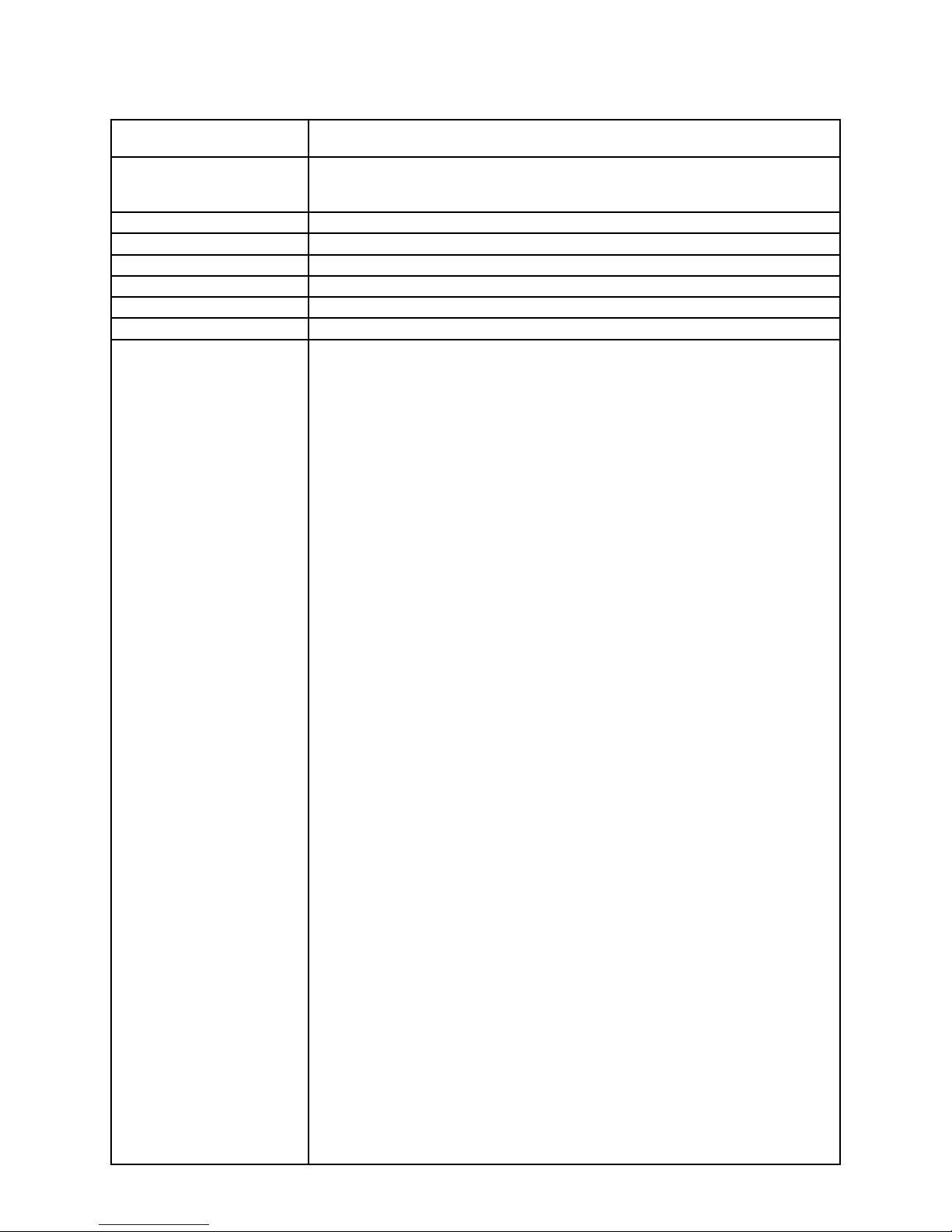
If the SLEEP indicator is on the display (either
flashing or steady), it means that the display is
blank because the watch’s Power Saving function
has turned off the display to conserve power.
Power Saving automatically turns off the display
and enters a sleep state whenever the watch is
left for a certain period where it is dark.
• Button operations are indicated using the
letters shown in the illustration.
• Each section of this manual provides you with
the information you need to perform operations
in each mode. Further details and technical
information can be found in the “Reference”
section.
• Most of the display examples in this manual
show only the digital display, without the analog
hands, as shown in the lower illustration.
, if
*
General Guide
• The illustration below shows which buttons you need to press to navigate
between modes.
• In any mode, press L to illuminate the display .
Alarm Mode
Data Recall Mode
D
Hold down
D .
Timekeeping Mode
▲
▲
▲
▲
D
Stopwatch Mode
Hand Setting Mode
D
▲
Press D .
▲
D
▲
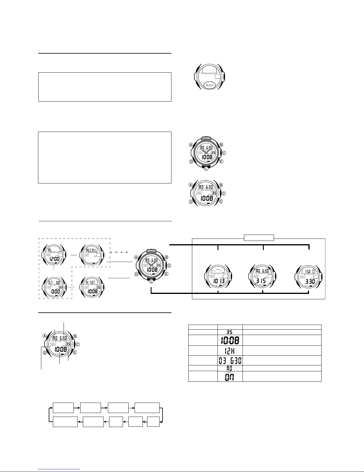
Timekeeping
Month – Day
Day of week
Seconds
Hour : Minutes
PM indicator
To set the digital time and date
1. In the Timekeeping Mode, hold down A until the seconds start to flash,
which indicates the setting screen.
D to move the flashing in the sequence shown below to select other
2. Press
settings.
Seconds
Power Saving
on/off
This watch features separate digital and analog
timekeeping. The procedures for setting the
digital time and analog time are different.
• Whenever you need to adjust both the digital
and the analog time settings, make sure you
adjust the digital setting first.
Digital Time and Date
Use the Timekeeping Mode to set and view a
digital display of the current time and date. When
setting the digital time, you can also configure
settings for the 12/24-hour format and the Power
Saving function.
Month
12/24-Hour
t
Forma
Year
Hour
Day of
eek
w
Minutes
Day
• From the Timekeeping Mode or another sensor mode, you can use buttons
B, C, or E to directly enter the mode assigned to it. From any other
mode, you must go to the Timekeeping Mode first.
Sensor Modes
▲
l
l
l
l
l
l
l
l
l
l
l
l
l
l
l
l
Press D.
▲
Press E.
Altimeter Mode
E to change it as
Button Operations
E
to reset the seconds to 00.
E (+) to change the setting.
to toggle between 12-hour (12H)
(+) to change the setting.
(+) to change the setting.
E to toggle Power Saving on (ON)
OFF).
Press B.
Thermometer Mode
3. When the setting you want to change is flashing, use
described below.
Setting
▲
Barometer/
l
l
l
l
l
l
l
l
Screen
Seconds
Hour, Minutes
12/24-Hour
format
Year , Month,
Day
Day of week
Power Saving
on/off
A to exit the setting screen.
4. Press
• Resetting the seconds only (without changing the hour or minute setting)
causes the analog minute hand setting to be adjusted automatically.
• See “Power Saving Function” for details about configuring Power Saving
settings.
Press C.
Digital Compass Mode
Press
Use
Use E
and 24-hour (24H) timekeeping.
Use E
Use E
Press
and off (
— 2 —
Page 5
Note
• Resetting the seconds to 00 while the current count is in the range of 30 to
59 causes the minutes to be increased by 1. In the range of 00 to 29, the
seconds are reset to
• With the 12-hour format, the P (PM) indicator appears on the display for
times in the range of noon to 11:59 p.m. and no indicator appears for times
in the range of midnight to 11:59 a.m.
• With the 24-hour format, times are displayed in the range of 0:00 to 23:59,
without any indicator.
• The 12-hour/24-hour timekeeping format you select in the Timekeeping
Mode is applied in all modes.
• The year can be set in the range of 2000 to 2039.
• The watch’s built-in full automatic calendar automatically makes allowances
for different month lengths and leap years. Once you set the date, there
should be no reason to change it except when battery power drops to Level
4.
Setting the Analog Time
Perform the procedure below when the time indicated by the analog hands
does not match the time of the digital display.
00 without changing the minutes.
To adjust the analog time
1.In the Timekeeping Mode, press D four times
to enter the Hand Setting Mode.
l
l
l
l
l
l
l
l
l
l
l
l
l
l
l
l
l
l
l
l
l
l
l
l
• Holding down E advances the analog time setting at high speed.
• If you need to advance the analog time setting a long way, hold down
E until the time starts advancing at high speed, and then press B.
This locks the high-speed hand movement, so you can release the two
buttons. High-speed hand movement continues until you press any
button. It will also stop automatically after the time advances 12 hours
or if an alarm starts to sound.
4. Press
A to exit the setting screen.
• To return to the Timekeeping Mode, press D.
2.Hold down
starts to flash, which indicates the analog time
setting screen.
3.Press
20 seconds.
A until the current digital time
E to advance the analog time setting by
Digital Compass
A built-in bearing sensor detects magnetic north. The watch uses this data to
display an angle value and four pointers indicating north, south, east, and
west. Direction readings are performed in the Digital Compass Mode.
• Y ou can calibrate the bearing sensor if you suspect the direction reading is
incorrect.
To enter and exit the Digital Compass Mode
1. While in the Timekeeping, Barometer/Thermometer, or Altimeter Mode,
press
C to enter the Digital Compass Mode.
• At this time, the watch immediately starts a Digital Compass operation.
After the first reading is obtained, the watch continues to take direction
readings automatically each second, for up to 20 seconds.
2. Press
D to return to the Timekeeping Mode.
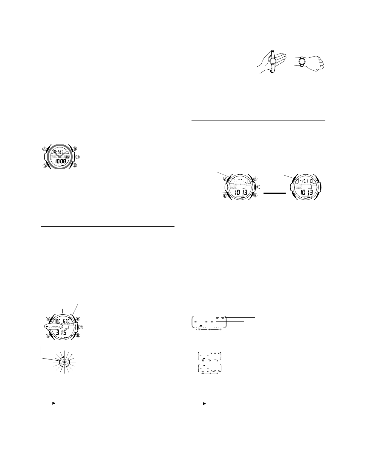
To take a direction reading
Magnetic north pointer
12 o’clock
position
l
l
l
l
l
l
l
l
l
l
Angle value (in degrees)
• During measurement the watch displays an angle value and four direction
pointers of the first reading, which change dynamically when the watch is
moved. After measurement is complete, the angle value and four direction
pointers are frozen in accordance with the last measurement.
• The indicator flashes on the display while a measurement is in progress.
N
NW
N
W
NW
W
W
W
S
W
SW
W
S
S
S
E
S
E
E
S
S
SE
1. Enter the Digital Compass Mode.
2. Place the watch on a flat surface or (if you are
wearing the watch), make sure that your wrist
is horizontal (in relation to the horizon).
3. Point the 12 o’clock position of the watch in
the direction you want to measure.
C to start a Digital Compass
4. Press
measurement operation.
• After direction measurement is complete, an
angle value appears on the display. The angle
value indicates the clockwise angle formed
between magnetic north (which is 0 degrees)
and the direction that the 12 o’clock position of
°
0
N
N
E
the watch is pointing.
N
• Also, four pointers appear to indicate magnetic
E
NE
north, south, east, and west.
E
N
• After the first reading is obtained, the watch
E
continues to take direction readings
automatically each second, for up to 20
seconds.
Note
• Note that taking a measurement
while the watch is not horizontal
(in relation to the horizon) can
result in large measurement
error.
• Any ongoing direction measurement operation is temporarily paused while
the watch is performing an alert operation (alarm or hourly time signal) or
while the watch’s backlight is turned on (by pressing
operation resumes for its remaining duration after the operation that caused
the pause is finished.
• See “Digital Compass Precautions” for other important information about
taking direction readings.
L). The measurement
Barometer/Thermometer
This watch uses a pressure sensor to measure air pressure (barometric
pressure) and a temperature sensor to measure temperature.
• You can calibrate the temperature sensor and the pressure sensor if you
suspect that readings are incorrect.
To take barometric pressure and temperature readings
Pressing B in the the Timekeeping Mode or in any of the other sensor
modes enters the Barometer/Thermometer Mode and automatically starts
taking barometric pressure and temperature measurements.
History Graph and
Barometric PressureHistory graph
l
l
l
l
l
l
l
l
Barometric
pressure
• It can take up to four or five seconds for the barometric pressure reading to
appear after you enter the Barometer/Thermometer Mode.
• Barometric pressure is displayed in units of 1hPa.
• The displayed barometric pressure value changes toxxxx hPa if a
measured barometric pressure falls outside the range of 260 hPa to 1100
hPa. The barometric pressure value will be displayed again as soon as the
measured barometric pressure is within the allowable range.
• Temperature is displayed in units of 0.1
• The displayed temperature value changes to xx. x
temperature falls outside the range of –10.0
value will be displayed again as soon as the measured temperature is
within the allowable range.
• Some countries refer to the barometric pressure unit hecto-pascal (hPa) as
millibars (mb). It really makes no difference, because 1hPa = 1mb.
• See “Barometer and Thermometer Precautions” for important precautions.
Barometric Pressure History Graph
Barometric pressure indicates changes in the atmosphere. By monitoring
these changes you can predict the weather with reasonable accuracy.
The barometric pressure history graph contains points that show you the
changes in barometric pressure readings taken by the watch for up to the last
18 hours. The time line along the bottom of the graph runs from left to right,
which means that the rightmost point on the graph is the latest reading. The
relative positions of the points on the graph indicate whether barometric
pressure is rising, falling, or holding relatively steady.
Relatively steady (within ±
• No point is plotted on the graph whenever a measurement operation fails
due to sensor malfunction, low battery power, or any other reason.
The following shows how to interpret the data that appears on the barometric
pressure history graph.
Temperature
Press B to
toggle between
screens.
▲
°
C.
°
Rising (rise greater than 3hPa)
Falling (fall greater than 3hPa)
A rising graph generally means improving weather.
A falling graph generally means deteriorating weather.
About Barometric and T emperature Measurements
• Barometric pressure and temperature measurement operations are
performed as soon as you enter the Barometer/Thermometer Mode. After
that, barometric pressure and temperature measurements are taken every
five seconds for the first three minutes.
indicator to the left of “BAROMETER” on the display flashes while a
• The
measurement is in progress.
• The barometer automatically takes measurements every three hours
(starting from midnight), regardless of what mode you are in. The results of
these measurements are used for plotting points on the barometric
pressure history graph.
• You can also perform a barometric pressure and temperature measurement
at any time by pressing
B in the Barometer/Thermometer Mode.
Temperature and
Barometric Pressure
l
l
l
l
l
l
l
l
▲
°
C if a measured
C to 60.0°C. The temperature
3hPa)
— 3 —
Page 6
Barometer and Thermometer Precautions
• The pressure sensor built into this watch measures changes in air
pressure, which you can then apply to your own weather predictions. It is
not intended for use as a precision instrument in official weather prediction
or reporting applications.
• Sudden temperature changes can affect pressure sensor readings.
• Temperature measurements are affected by your body temperature (while
you are wearing the watch), direct sunlight, and moisture. To achieve a
more accurate temperature measurement, remove the watch from your
wrist, place it in a well ventilated location out of direct sunlight, and wipe off
all moisture from the case. It takes approximately 20 to 30 minutes for the
case of the watch to reach the actual surrounding temperature.
Altimeter
A built-in altimeter uses a pressure sensor to detect the current air pressure,
which is then used to estimate the current altitude. The watch is preprogrammed with ISA (International Standard Atmosphere) preset values,
which are used to convert air pressure readings to altitude values. If you
preset a reference altitude, the watch will also calculate the current relative
altitude based on your preset value. Memory is also provided for the storage
of altimeter data.
Important!
• This watch estimates altitude based on air pressure. This means that
altitude readings for the same location may vary if air pressure changes.
• This watch employs a semiconductor pressure sensor, which is affected by
temperature changes. Make sure that the watch is not being exposed to
temperature changes while you are taking altitude measurements.
• To avoid the effect of sudden temperature changes on measurement, wear
the watch so it is in direct contact with your wrist during measurement.
• Do not rely upon this watch for altitude measurements or perform button
operations while engaging in sports where there are sudden altitude
changes, while sky diving, hang gliding, or paragliding, or while riding a
gyrocopter, glider, or any other aircraft.
• Do not use this watch for measuring altitude in applications that demand
professional or industrial level precision.
• Remember that the air inside of a commercial aircraft is pressurized.
Because of this, the readings produced by this watch will not match the
altitude readings announced or indicated by the flight crew.
How the Altimeter Works
With the Preset Values (No Reference Altitude)
• The watch measures the air pressure at your current location and uses the
built-in ISA values to convert it to the equivalent altitude.
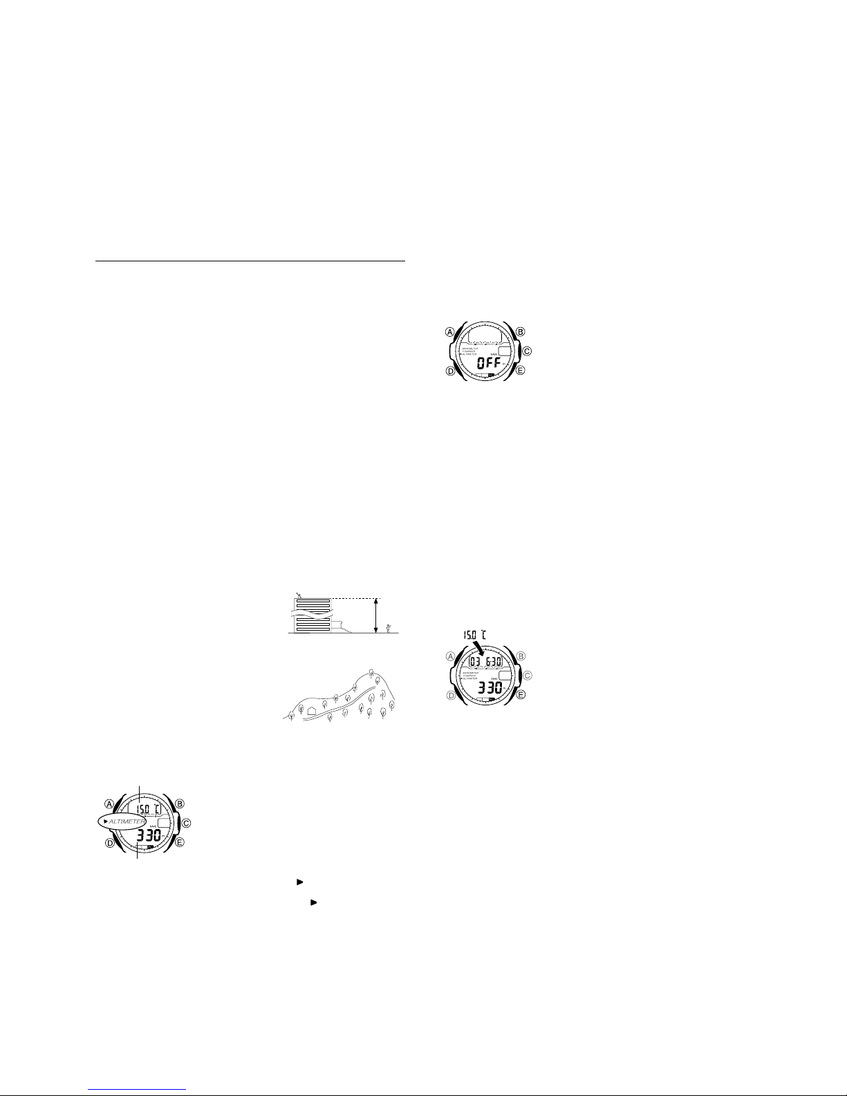
With a Reference Altitude
• If you set a reference altitude, the watch
uses that value when calculating altitude
based on air pressure.
• To determine the height of a tall building,
set the reference altitude to 0 on the
ground floor. Note, however , that you may
not be able to get a good reading if the
building is pressurized or air-conditioned.
• When mountain climbing, you can set the
reference value in accordance with a
marker along the way or altitude
information from a map. After you do this,
the altitude readings produced by the
watch will be more accurate than they
would without a reference altitude.
To take an altitude reading
Pressing E in the Timekeeping Mode or in any
Temperature
l
l
l
l
l
l
l
l
l
Altitude
of the other sensor modes enters the Altimeter
Mode and automatically starts altitude
measurement.
• It can take up to four or five seconds for the
altitude reading to appear after you enter the
Altimeter Mode.
• The Altimeter Mode screen also displays the
current temperature. See “Barometer/
Thermometer” for more information.
• During the first three minutes after entering the
Altimeter Mode, the
display and measurements are taken every five
seconds. After that, the
flashing and remains on the display as
measurements are taken every two minutes.
A
400
indicator flashes on the
indicator stops
B
• Pressing E causes the measurement operation to restart from the
beginning of the cycle described above.
• Altitude is displayed in units of 5 meters.
• The measurement range for altitude is –700 to 10,000 meters.
• The measured altitude may be a negative value in cases where there is a
reference altitude value set or because of certain atmospheric conditions.
• The displayed altitude value changes to
altitude falls outside the measurement range. The altitude value will be
displayed again as soon as the measured altitude is within the allowable
range.
Setting a Reference Altitude
After you set a reference altitude, the watch adjusts its air-pressure-to-altitude
conversion calculation accordingly. The altitude measurements produced by
this watch are subject to error caused by changes in air pressure. Because of
this, we recommend that you update the reference altitude whenever one is
available during your climb.
xxxxx
meters if a measured
To set a reference altitude
1. In the Altimeter Mode, hold down A for about
two seconds until the watch beeps and the
display goes blank. About four or five seconds
after that,
OFF
l
l
l
l
l
l
l
l
l
l
l
l
l
l
l
l
l
l
l
• You can set the reference altitude within the range of –10,000 to 10,000
meters.
• Pressing E and B at the same time returns to
altitude), so the watch performs air pressure to altitude conversions
based on preset data only.
3. Press
A to exit the setting screen.
Altitude Records
Storing altitude data in memory creates an altitude record. If a reading is
greater than all of the other altitude readings currently stored in memory, it is
stored in the maximum altitude record. The following describes the contents
of each type of record.
Recording date (year, month, day), time, and altitude: Up to 41 records
Maximum altitude (including recording date and time): 1 record
• The maximum altitude record shows information about the altitude record
that has the greatest altitude value. The maximum altitude record is
updated any time a reading produces an altitude that is greater than that of
the current maximum altitude record.
altitude value (if set) will flash on the display.
• If
OFF
value does not appear at this time, press
to return to the Altimeter Mode screen, and
perform step 1 again.
2. Press
reference altitude value by 5 meters.
or the current reference
or the current reference altitude
E (+) or B (–) to change the current
OFF
(no reference
A
To store an altitude record in memory
In the Altimeter Mode, hold down E for about
one second until the watch beeps. This indicates
that a record of the altitude reading (date, time,
and altitude) has been stored in memory.
• You can recall data in memory using the Data
Recall Mode.
• Note that there is enough memory to store a
total of 41 records. If there are already 41
records in memory, storing another one
automatically deletes the oldest record to make
room for the new one.
To view altitude record data
1. Use D to enter the Data Recall Mode.
• The message RECALL appears for about one second, followed by
maximum altitude record.
2. Press
E to cycle through the altitude record screens in the sequence
shown below.
• The maximum altitude record appears first. After that, each press of E
scrolls through records in sequence, starting from the oldest record.
• For each record, the lower part of the display alternates at one-second
intervals between the recording time and altitude value.
• If an error occurs while altitude data is being stored in memory or if there is
no altitude data in memory,
value on the corresponding altitude record screen.
xxxx is shown for the measured altitude
— 4 —
Page 7
Data Recall Mode
One
second
Maximum Data
▲
E
Recording date
(Year , Month – Day)
Alternates at
1-second
intervals.
▲
▲
Recording time
(Hour : Minutes)
Press E.
▲
▲
E
Oldest DataNewest Data
Altitude
Stopwatch
1/100 second
Seconds
Hours Minutes
To measure times with the stopwatch
The stopwatch lets you measure elapsed time,
split times, and two finishes.
•
The display range of the stopwatch is 23 hours,
59 minutes, 59.99 seconds.
•
The stopwatch continues to run, restarting from
zero after it reaches its limit, until you stop it.
•
The stopwatch measurement operation
continues even if you exit the Stopwatch Mode.
•
Exiting the Stopwatch Mode while a split time is
frozen on the display clears the split time and
returns to elapsed time measurement.
•
All of the operations in this section are
performed in the Stopwatch Mode, which you
enter by pressing
D
.
Deleting the Maximum Altitude Record Data
Use the following procedure when you want to delete the data in the
maximum altitude record. Note that you can delete maximum altitude record
data only. You cannot delete the data of any of the other altitude records.
To delete the maximum altitude record data
1. Use the procedure under “To view altitude record data” to display the
maximum altitude record.
•
The maximum altitude record is the one with MAX next to both the time
and altitude values.
A
2. Hold down
for about two seconds. This will delete the data.
Alarm
After you set (and turn on) the daily alarm, the
Alarm on indicator
Hourly time signal on
indicator
Alarm time (Hour : Minutes)
To set the alarm time
l
l
l
l
l
l
l
l
l
l
l
l
l
Alarm Operation
The alarm sounds at the preset time for about 10 seconds (in all modes), or
until you stop it by pressing any button.
To test the alarm
In the Alarm Mode, hold down E to sound the alarm.
To turn the daily alarm and the Hourly Time Signal on and off
In the Alarm Mode, press E to cycle through the settings shown below.
Alarm On Indicator / Hourly Time Signal On Indicator
alarm tone sounds when the alarm time is
reached. Y ou can also turn on an Hourly Time
Signal that causes the watch to beep twice every
hour on the hour.
•
All of the operations in this section are
performed in the Alarm Mode, which you enter
by pressing
1. In the Alarm Mode, hold down A until the
hour setting of the alarm time starts to flash,
which indicates the setting screen.
•
2. Press
hour and minute settings.
3. While a setting is flashing, use
it.
•
4. Press
D
.
This automatically turns on the alarm.
D
to move the flashing between the
E
to increase
When setting the alarm time using the 12-
hour format, take care to set the time
correctly as a.m. (no indicator) or p.m. (P
indicator).
A
to exit the setting screen.
Elapsed Time
EEEB
▲ ▲ ▲
E
▲ ▲ ▲
▲ ▲ ▲
▲ ▲ ▲
Start Stop Re-start Stop Clear
Split Time
EBEB
B
Start Split Split release Stop Clear
(SPL displayed)
Two Finishes
EE
BBB
Start Split Stop Split release Clear
First runner
finishes.
Display time
of first runner.
Second runner
finishes.
Display time of
second runner.
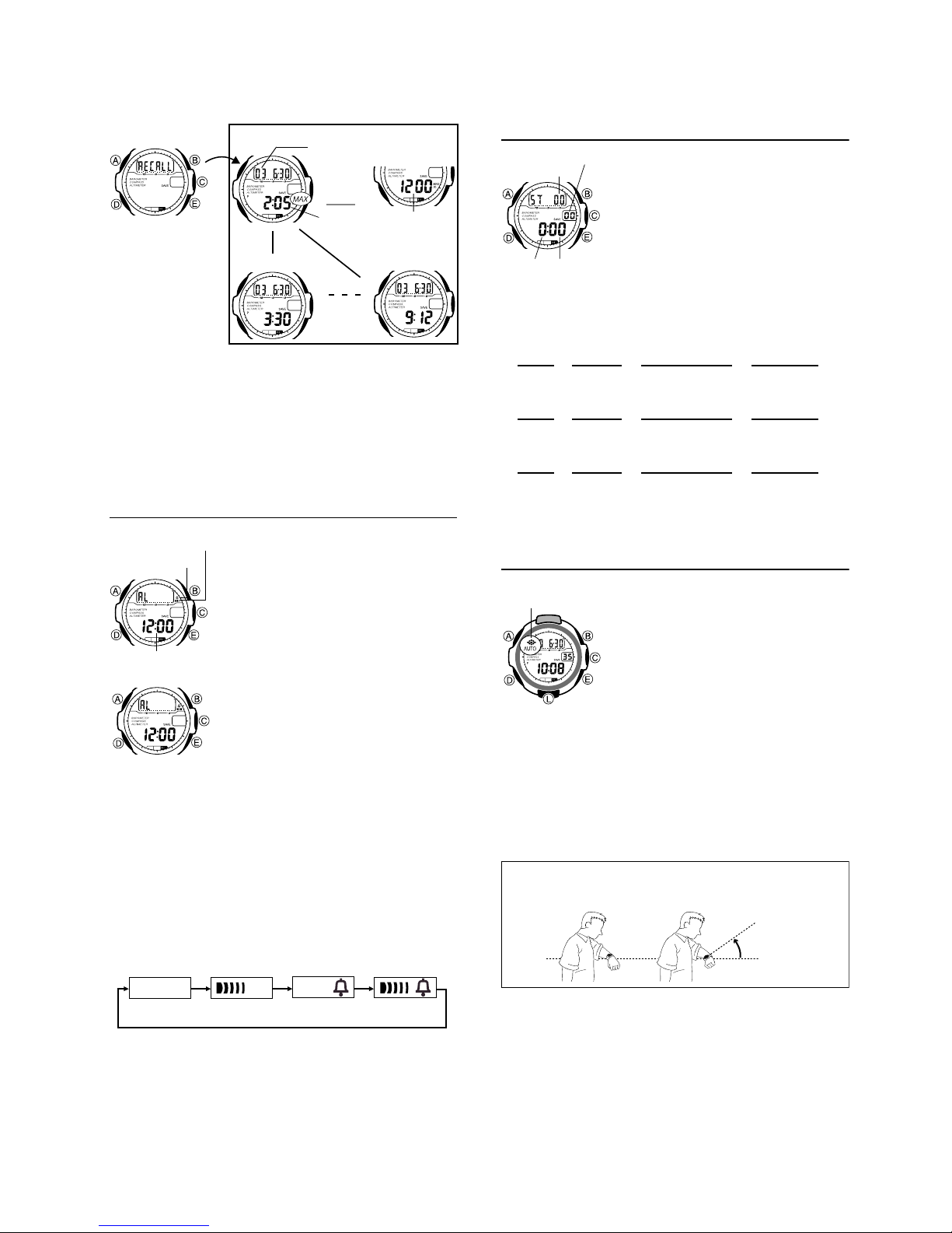
Backlight
Auto light switch on
indicator
To turn on the backlight manually
Press L in any mode to illuminate the display for about two seconds.
•
Backlight operation is disabled during the bearing sensor calibration
procedure.
•
The above operation turns on the backlight regardless of the current auto
light switch setting.
About the Auto Light Switch
Turning on the auto light switch causes the backlight to turn on for about two
seconds, whenever you position your wrist as described below in any mode.
Note that this watch features a “Full Auto EL Light”, so the auto light switch
operates only when available light is below a certain level. It does not turn on
the backlight under bright light.
Moving the watch to a position that is parallel to the ground and then tilting
it towards you more than 40 degrees causes the backlight to turn on.
•
Wear the watch on the outside of your left wrist.
The backlight uses an EL (electro-luminescent)
panel that causes the entire display to glow for
easy reading in the dark. The watch’s auto light
switch automatically turns on the backlight when
you angle the watch towards your face.
•
The auto light switch must be turned on
(indicated by the auto light switch on indicator)
for it to operate.
•
See “Backlight Precautions” for other important
information about using the backlight.
Parallel to
ground
More than
40
°
Alarm Off
Signal Off
•
The alarm on indicator and the Hourly Time Signal on indicator are shown
on the display in all modes while these functions are turned on.
Alarm On
Signal Off
Alarm Off
Signal On
Alarm On
Signal On
— 5 —
Warning!
•
Always make sure you are in a safe place whenever you are reading
the display of the watch using the auto light switch. Be especially
careful when running or engaged in any other activity that can result
in accident or injury. Also take care that sudden illumination by the
auto light switch does not surprise or distract others around you.
•
When you are wearing the watch, make sure that its auto light switch
is turned off before riding on a bicycle or operating a motorcycle or
any other motor vehicle. Sudden and unintended operation of the auto
light switch can create a distraction, which can result in a traffic
accident and serious personal injury.
Page 8

To turn the auto light switch on and off
In the Timekeeping Mode, hold down B for about two seconds to toggle the
auto light switch on (
• If you are in the Timekeeping Mode when you press B, the watch will go
directly into the Barometer/Thermometer Mode. Keep
the auto light switch turns on or off. After that, you can return to the
Timekeeping Mode by pressing
• The auto light switch on indicator ( ) is on the display in all modes while
the auto light switch is turned on.
• The auto light switch is always disabled, regardless of its on/off setting,
when any one of the following conditions exists.
While a direction measurement operation is being performed in the
Digital Compass Mode
While a bearing sensor calibration operation is being performed in the
Digital Compass Mode
While the Hand Setting Mode setting screen is on the display
• The backlight may not light right away if you raise the watch to your face
while a barometric pressure or altitude measurement operation is in
progress.
displayed) or off ( not displayed).
B depressed until
D.
Questions & Answers
Question: What causes incorrect direction readings?
Answer:
• Incorrect bidirectional calibration. Perform bidirectional calibration.
• Nearby source of strong magnetism, such as a household appliance, a
large steel bridge, a steel beam, overhead wires, etc., or an attempt to
perform direction measurement on a train, boat, etc. Move away from large
metal objects and try again. Note that digital compass operation cannot be
performed inside a train, boat, etc.
Question: What causes different direction readings to produce different
Answer: Magnetism generated by nearby high-tension wires is interfering
Question: Why am I having problems taking direction readings indoors ?
Answer: A TV, personal computer, speakers, or some other object is
Question: How does the altimeter work?
Answer: Generally, air pressure and temperature decrease as altitude
• Note that the following conditions will prevent you from obtaining accurate
There are two standard methods of expressing altitude: Absolute altitude and
relative altitude. Absolute altitude expresses an absolute height above sea
level. Relative altitude expresses the difference between the height of two
different places.
results at the same location ?
with detection of terrestrial magnetism. Move away from the hightension wires and try again.
interfering with terrestrial magnetism readings. Move away from
the object causing the interference or take the direction reading
outdoors. Indoor direction readings are particularly difficult inside
ferro-concrete structures. Remember that you will not be able to
take direction readings inside of trains, airplanes, etc.
increases. This watch bases its altitude measurements on
International Standard Atmosphere (ISA) values stipulated by the
International Civil Aviation Organization (ICAO). These values
define relationships between altitude, air pressure, and
temperature.
Altitude Air Pressure Temperature
a
616 hP
4000 m
3500 m
3000 m
2500 m
2000 m
1500 m
1000 m
500 m
0 m
Source: International Civil Aviation Organization
readings:
When air pressure changes because of changes in the weather
Extreme temperature changes
When the watch itself is subjected to strong impact
About 8 hPa per 100 m
a
701 hP
About 9 hPa per 100 m
795 hP
a
About 10 hPa per 100 m
About 11 hPa per 100 m
899 hPa
About 12 hPa per 100 m
Height of building 130 m
(Relative altitude)
°
C
–11
°
C
–4.5
About 6.5
per 1000 m
2
°
C
°
C
8.5
°
C1013 hPa
15
Rooftop at an altitude of
230 m above sea level
(Altitude above sea
level)
Sea
°
C
Precautions Concerning Simultaneous Measurement of Altitude and
Temperature
Though you can perform altitude and temperature measurements at the same
time, you should remember that each of these measurements requires
different conditions for best results. With temperature measurement, it is best
to remove the watch from your wrist in order to eliminate the effects of body
heat. In the case of altitude measurement, on the other hand, it is better to
leave the watch on your wrist, because doing so keeps the watch at a
constant temperature, which contributes to more accurate altitude
measurements.
The following describes what you should do to give priority to either altitude or
temperature.
• To give altitude measurement priority, leave the watch on your wrist or in
any other location where the temperature of the watch is kept constant.
• To give temperature measurement priority, remove the watch from your
wrist and allow it to hang freely from your bag or in another location where
it is not exposed to direct sunlight. Note that removing the watch from your
wrist can momentarily affect pressure sensor readings.
Question: How does the barometer work?
Answer: Barometric pressure indicates changes in the atmosphere, and by
monitoring these changes you can predict the weather with
reasonable accuracy. Rising atmospheric pressure indicates good
weather, while falling pressure indicates deteriorating weather
conditions.
The barometric pressures that you see in the newspaper and on
the TV weather report are measurements corrected to values
measured at 0 m sea level.
Battery
Solar cell
Important!
• Storing the watch for long periods in an area where there is no light or
wearing it in such a way that it is blocked from exposure to light can cause
rechargeable battery power to run down. Be sure that the watch is normally
exposed to bright light whenever possible.
• This watch employs a solar cell that converts light into electricity, which
charges a built-in rechargeable battery. Normally, the rechargeable battery
should not need replacement, but after very long use over a number of
years, the rechargeable battery may lose its ability to achieve a full charge.
If you experience problems getting the rechargeable battery to a full charge,
contact your dealer or CASIO distributor about having the rechargeable
battery replaced.
• The rechargeable battery should be replaced with a CASIO-specified
CTL1616 battery only. Other rechargeable batteries can cause damage to
the watch.
• All data stored in memory is deleted, and the current time and all other
settings return to their initial factory defaults whenever battery power drops
to Level 4 and when you have the battery replaced.
• Turn on the watch’s Power Saving function and keep it in an area normally
exposed to bright light when storing it for long periods. This helps to keep
the rechargeable battery from going dead.
Battery Power Indicator
The battery power indicator on the display shows you the current status of the
rechargeable battery’s power.
Battery power
indicator
This watch is equipped with a solar cell and a
rechargeable battery (secondary battery) that is
charged by the electrical power produced by the
solar cell. The illustration shown nearby shows
how you should position the watch for charging.
Example: Orient the watch so its face is pointing
at a light source.
• Note that charging efficiency
drops when any part of the solar
cell is blocked by clothing, etc.
• The illustration shows how to
position a watch with a resin band.
Battery Power
Level
1
2
3
4
Indicator
l
l
l
l
l
l
l
l
l
l
l
l
l
l
l
l
l
l
l
l
l
(Charge Soon Alert)
Function Status
All functions enabled.
All functions enabled.
Except for timekeeping and
battery power indicator, all
functions and display indicators
are disabled.
All functions disabled.
— 6 —
Page 9

• The flashing CHARGE indicator at Level 3 tells you that battery power is
very low, and that exposure to bright light for charging is required as soon
as possible.
• At Level 4, all functions are disabled and settings return to their initial
factory defaults. Functions are enabled once again after the rechargeable
battery is charged, but you need to set the time and date, after the battery
reaches Level 2 (indicated by the M indicator) from Level 4. Y ou will not be
able to set any of the other settings until the battery reaches Level 1
(indicated by the H indicator) after dropping to Level 4.
• Display indicators reappear as soon as the battery is charged from Level 4
to Level 3.
• Leaving the watch in direct sunlight or some other very strong light source
can cause the battery power indicator to temporarily show a reading that is
higher than the actual battery level. The correct battery power indicator
should appear after a few minutes.
• Even if battery power is at Level 1 or Level 2, the Digital Compass Mode,
Barometer/Thermometer Mode, or Altimeter Mode sensor may be disabled
if there is not enough voltage available to power it sufficiently . This condition
is indicated on the display as shown in the table below. Sensor operation
should resume when battery voltage returns to normal levels.
Mode
Digital
Compass
Barometer/
Thermometer
Altitude
• The last measured data may still remain on the display if you enter one of
the sensor modes while RECOV is on the display.
• If RECOV appears frequently , it probably means that remaining battery
power is low. Leave the watch in bright light to allow it to charge.
Charging Precautions
Certain charging conditions can cause the watch to become very hot. Avoid
leaving the watch in the areas described below whenever charging its
rechargeable battery.
Also note that allowing the watch to become very hot can cause its liquid
crystal display to black out. The appearance of the LCD should become
normal again when the watch returns to a lower temperature.
Warning!
Leaving the watch in bright light to charge its rechargeable battery can
cause it to become quite hot. Take care when handling the watch to
avoid burn injury. The watch can become particularly hot when exposed
to the following conditions for long periods.
• On the dashboard of a car parked in direct sunlight
• Too close to an incandescent lamp
• Under direct sunlight
Charging Guide
After a full charge, timekeeping remains enabled for up to about six months,
while the watch is used under the conditions described below.
Operating Conditions
•
Watch is not exposed to light
•
Display on 18 hours per day, sleep state 6 hours per day
•
1 backlight operation (2 seconds) per day
•
10 seconds of alarm operation per day
•
10 digital compass operations per week
•
10 hours of altimeter measurements, once per month
Charge Times
Exposing the watch to light for the periods shown below each day restores
the power used by the above operating conditions.
Display Indication for
Low Voltage Upon
Entering the Mode
xxx
xxxx
Blank
• If you use the backlight or the alarm a number
of times during a short period, RECOV appears
on the display and the backlight, alarm, hourly
time signal, and sensor operations become
disabled until battery power recovers.
After some time, battery power will recover and
RECOV will disappear, indicating that the
above functions are enabled again.
Exposure Level (Brightness)
Display Indication for Low
Voltage During
Measurement
Last measured angle
value
Last measured pressure
value
Last measured altitude
Approximate
Exposure Time
Outdoor Sunlight (50,000 lux)
Sunlight Through a Window (10,000 lux)
Daylight Through a Window on a Cloudy Day (5,000 lux)
Indoor Fluorescent Lighting (500 lux)
5 minutes
24 minutes
48 minutes
8 hours
• Stable operation is promoted by frequent charging.
Recovery Times
The table below shows the amount exposure that is required to take the
battery from one level to the next.
Exposure Level
(Brightness)
Outdoor Sunlight
(50,000 lux)
Sunlight Through a
Window (10,000 lux)
Daylight Through a
Window on a Cloudy
Day (5000 lux)
Indoor Fluorescent
Lighting (500 lux)
• The above exposure time values are all for reference only . Actual required
exposure times depend on lighting conditions.
Approximate Exposure Time
Level 4 Level 3 Level 2 Level 1
▲
▲
1 hour 15 hours 4 hours
4 hours 76 hours 21 hours
6 hours 124 hours 34 hours
56 hours - - - - - - - - - - - - - - - -
Reference
This section contains more detailed and technical information about watch
operation. It also contains important precautions and notes about the various
features and functions of this watch.
Sensor Malfunction Indicator
Should the pressure sensor or direction sensor malfunction, the message
Err
appears on the display for about two seconds, and then sensor
operation is disabled.
Direction
Measurement
l
l
l
l
l
l
l
l
l
• If
Err
appears while a measurement operation is being performed in a
sensor mode, restart the measurement. If
again, it can mean there is something wrong with the sensor. Take the
watch to your original dealer or nearest authorized CASIO distributor for
inspection and maintenance.
• Even if battery power is at Level 1 or Level 2, the Digital Compass Mode,
Barometer/Thermometer Mode, or Altimeter Mode sensor may be disabled
if there is not enough voltage available to power it sufficiently. In this case,
the
Err
message appears on the display when you switch to the
Timekeeping Mode. This does not indicate malfunction, and sensor
operation should resume once battery voltage returns to its normal level.
• Even if battery power is at Level 1 or Level 2, the
on the Timekeeping Mode screen if there is not enough voltage available to
power the pressure sensor sufficiently during a barometric pressure
measurement. This does not indicate malfunction, and sensor operation
should resume once battery voltage returns to its normal level.
• The message
enter the Timekeeping Mode from one of the sensor modes while
measurement is in progress. Normally, the
an instant as the watch cancels the ongoing sensor operation, and it does
not indicate malfunction of the watch or the sensor. However, if the
message remains on the display, it can mean that your watch is
malfunctioning.
Whenever you have a sensor malfunction, be sure to take the watch to
your original dealer or nearest authorized CASIO distributor as soon as
possible.
Auto Return Features
• The watch automatically returns to the Timekeeping Mode if you do not
perform any button operation for two or three minutes in any mode except
for the Stopwatch Mode and Altimeter Mode.
• If you do not perform any button operation while in the Altimeter Mode, the
watch automatically returns to the Timekeeping Mode after nine or 10
hours.
• If you leave a screen with flashing digits on the display for two or three
minutes without performing any operation, the watch automatically saves
anything you have input up to that point and exits the setting screen.
Direct Timekeeping Mode Access
Holding down D while in the Data Recall Mode, Alarm Mode, or Stopwatch
Mode goes directly to the Timekeeping Mode.
• Note that the above does not work while a setting screen (one with flashing
digits, etc.) is on the display.
Err
Barometric
Pressure
Measurements
l
l
l
l
l
l
l
l
l
Err
appears on the display
Altitude
Measurement
l
l
l
l
l
l
l
l
l
Err
message will appear
(error) may appear on the display momentarily if you
Err
message appears for just
Err
▲
— 7 —
Page 10

Scrolling
k
The E and B buttons are used in various modes and setting screens to
scroll through data on the display. In most cases, holding down these buttons
during a scroll operation scrolls through the data at high speed.
Power Saving Function
When turned on, the Power Saving function automatically puts the watch into
a sleep state whenever it is left for a certain period in an area where it is dark.
The table below shows how watch functions are affected by the Power Saving
function.
Elapsed Time in
Dark
60 to 70 minutes
6 or 7 days
• Wearing the watch inside the sleeve of clothing can cause it to enter the
sleep state.
• The watch will not enter the sleep state while the digital time is between
6:00 AM and 9:59 PM. If the watch is already in the sleep state when the
digital time reaches 6:00 AM, however, it will remain in the sleep state.
• The watch will not enter the sleep state while it is in the Digital Compass
Mode, Barometer/Thermometer Mode, Altimeter Mode, or Stopwatch
Mode. When the watch is left in any mode besides the Stopwatch Mode,
the watch will return to the Timekeeping Mode automatically after a specific
amount of time. Then if left in the dark for the elapsed time indicated in the
table above, the watch will enter the sleep state.
Display
Blank, with
SLEEP flashing
Blank, with
SLEEP not
flashing
Display is off, but all functions are
enabled and analog hand
operation is maintained.
All functions are disabled, but
timekeeping (digital and analog)
is maintained.
Operation
To recover from the sleep state
Perform any one of the following operations.
• Move the watch to a well-lit area. It can take up to two seconds for the
display to turn on.
• Press any button.
• Angle the watch towards your face for reading.
To turn Power Saving on and off
1. In the Timekeeping Mode, hold down A until
the seconds start to flash, which indicates the
setting screen.
2. Press
l
l
l
l
l
l
l
l
l
l
l
l
l
l
l
l
Backlight Precautions
• The electro-luminescent panel that provides illumination loses power after
very long use.
• The illumination provided by the backlight may be hard to see when viewed
under direct sunlight.
• The backlight automatically turns off whenever an alarm sounds.
• The watch may emit an audible sound whenever the display is illuminated.
This is due to vibration of the EL panel used for illumination, and does not
indicate malfunction.
• Frequent use of the backlight runs down the battery.
Auto light switch precautions
• Wearing the watch on the inside of your wrist, movement of your arm, or
vibration of your arm can cause frequent activation of the auto light switch
and illumination of the display. To avoid running down the battery, turn off
the auto light switch whenever engaging in activities that might cause
frequent illumination of the display.
• Note that wearing the watch under your sleeve while the auto light switch is
turned on can cause frequent illumination of the display and can run down
the battery.
More than 15 degrees
too high
• Static electricity or magnetic force can interfere with proper operation of the
auto light switch. If the backlight does not light, try moving the watch back to
the starting position (parallel with the ground) and then tilt it back toward
you again. If this does not work, drop your arm all the way down so it hangs
at your side, and then bring it back up again.
• Under certain conditions, the backlight may not light until about one second
after you turn the face of the watch towards you. This does not necessarily
indicate malfunction of the backlight.
• Y ou may notice a very faint clicking sound coming from the watch when it is
shaken back and forth. This sound is caused by mechanical operation of
the auto light switch, and does not indicate a problem with the watch.
D eight times until the Power Saving
on/off screen appears.
E to toggle Power Saving on (
3. Press
off (
OFF
4. Press
• The Power Saving on indicator (SAVE) is on
• The backlight may not light if the face of the
watch is more than 15 degrees above or below
parallel. Make sure that the back of your hand
is parallel to the ground.
• The backlight turns off in about two seconds,
even if you keep the watch pointed towards
your face.
).
A to exit the setting screen.
the display in all modes while the Power Saving
is turned on.
ON
) and
Digital Compass Precautions
This watch features a built-in magnetic bearing sensor that detects terrestrial
magnetism. This means that north indicated by this watch is magnetic north,
which is somewhat different from true polar north. The magnetic north pole is
located in northern Canada, while the magnetic south pole is in southern
Australia. Note that the difference between magnetic north and true north as
measured with all magnetic compasses tends to be greater as one gets
closer to either of the magnetic poles. Y o u should also remember that some
maps indicate true north (instead of magnetic north), and so you should make
allowances when using such maps with this watch.
Location
• Taking a direction reading when you are near a source of strong magnetism
can cause large errors in readings. Because of this, you should avoid taking
direction readings while in the vicinity of the following types of objects:
permanent magnets (magnetic necklaces, etc.), concentrations of metal
(metal doors, lockers, etc.), high tension wires, aerial wires, household
appliances (TVs, personal computers, washing machines, freezers, etc.)
• Accurate direction readings are impossible while in a train, boat, air plane,
etc.
• Accurate readings are also impossible indoors, especially inside ferro-
concrete structures. This is because the metal framework of such structures
picks up magnetism from appliances, etc.
• Movement of the analog hands during digital compass operation in an area
where terrestrial magnetism is weak can cause the pointer position and
angle value to be slightly off.
Storage
• The precision of the bearing sensor may deteriorate if the watch becomes
magnetized. Because of this, you should be sure to store the watch away
from magnets or any other sources of strong magnetism, including:
permanent magnets (magnetic necklaces, etc.) and household appliances
(TVs, personal computers, washing machines, freezers, etc.)
• Whenever you suspect that the watch may have become magnetized,
perform one of the calibration procedures under “Calibrating the Bearing
Sensor”.
Calibrating the Bearing Sensor
Whenever you suspect that direction readings produced by the watch are
wrong, you should calibrate it. Y ou can use either one of two calibration
procedures:
Use bidirectional calibration when you want to take readings within an area
exposed to magnetic force. This type of calibration should be used if the
watch becomes magnetized for any reason.
With northerly calibration, you “teach” the watch which way is north (which
you have to determine with another compass or some other means). You
could use this calibration procedure, for example, to set the watch to indicate
true north instead of magnetic north.
Important!
• If you want to perform both bidirectional and northerly calibration, be sure
• The more correctly you perform bidirectional calibration, the better the
Precautions about bidirectional calibration
• Y ou can use any two opposing directions for bidirectional calibration. You
• Make sure that you do not move the watch while calibration of either
• You should perform bidirectional calibration in an environment that is the
bidirectional calibration
to perform bidirectional calibration first, and then perform northerly
calibration. This is necessary because bidirectional calibration cancels any
previously set northerly calibration setting.
accuracy of the bearing sensor readouts. Y ou should perform bidirectional
calibration whenever you change environments where you use the bearing
sensor, and whenever you feel that the bearing sensor is producing
incorrect readings.
must, however, make sure that they are 180 degrees opposite each other.
Remember that if you perform the procedure incorrectly, you will get wrong
bearing sensor readings.
or
northerly calibration
.
direction is in progress.
same as that where you plan to be taking direction readings. If you plan to
take direction readings in an open field, for example, calibrate in an open
field.
To perform bidirectional calibration
l
l
l
l
l
l
l
l
l
l
l
3. Place the watch on a level surface facing any direction you want, and
press
C to calibrate the first direction.
xxx
” is shown on the display while calibration is being performed. This
• “
changes to
position when calibration of the first direction is complete. This means
that the watch is ready for calibration of the second direction.
4. Rotate the watch 180 degrees.
5. Press
x2x
C again to calibrate the second direction.
1. Press C to enter the Digital Compass Mode.
2. Hold down
appears on the display, which indicates the
setting screen.
• At this time, the magnetic north pointer
A for about one second until
flashes at the 12 o’clock position to indicate
that the watch is ready to calibrate the first
direction.
x1x
and the magnetic north pointer flashes at the 6 o’cloc
— 8 —
Page 11

• “
xxx
” is shown on the display while calibration is being performed. The
Digital Compass Mode screen (showing the angle value) appears when
calibration is complete.
• Note that the calibration operation will not start if you press C if the
seconds count of the Timekeeping Mode time is in the vicinity of 00, 20, or
xxx
40. If “
then try again.
• If “
screen, it means that there is something wrong with the sensor. Press
return to the Digital Compass Mode screen and then try starting the
calibration operation again. If
dealer or nearest authorized CASIO distributor to have the watch checked.
” does not appear when you press C, wait a few seconds and
xxx
” appears and then changes to
Err
(error) on the calibration
Err
keeps appearing, contact your original
A to
To perform northerly calibration
l
l
l
l
l
l
l
l
l
l
l
3. Place the watch on a level surface, and position it so that its 12 o’clock
position points north (as measured with another compass).
4. Press
C to start the calibration operation.
• “
xxx
” is shown on the display while calibration is being performed. The
Digital Compass Mode screen appears (with 0
value) when calibration is complete.
• Note that the calibration operation will not start if you press C if the
seconds count of the Timekeeping Mode time is in the vicinity of 00, 20, or
xxx
40. If “
then try again.
• If “
screen, it means that there is something wrong with the sensor. Press
return to the Digital Compass Mode screen and then try starting the
calibration operation again. If
dealer or nearest authorized CASIO distributor to have the watch checked.
Calibrating the Temperature Sensor
The temperature sensor of this watch is calibrated at the factory before
shipment, and further adjustment is normally not required. If you notice
serious errors in the temperature readings produced by the watch, you can
calibrate the sensor to correct the errors.
Important!
Incorrectly calibrating the temperature sensor can result in incorrect readings.
Carefully read the following before doing anything.
• Compare the readings produced by the watch with those of another reliable
and accurate thermometer.
• If adjustment is required, remove the watch from your wrist and wait for 20
or 30 minutes to give the temperature of the watch time to stabilize.
” does not appear when you press C, wait a few seconds and
xxx
” appears and then changes to
1. While in the Digital Compass Mode, hold
down
A for about one second until
appears on the display, which indicates the
setting screen.
2. Press
D to start the northerly calibration
procedure.
• At this time,
display.
Err
xNx
(north) appears on the
°
indicated as the angle
Err
(error) on the calibration
keeps appearing, contact your original
x1x
A to
To calibrate the temperature sensor
1. Press B to enter the Barometer/
l
l
l
l
l
l
l
l
l
l
l
l
l
l
l
l
3. Press
E (+) or B (–) to change the displayed temperature by 0.1
• Pressing B and E at the same time returns to the factory calibration
(
OFF
).
4. Press
A to return to the Barometer/Thermometer Mode screen.
Thermometer Mode.
2. Hold down
flash in the upper part of the display. This is
the setting screen.
• If the temperature sensor was previously
• After about four or five seconds, the lower
A until
OFF
or
xxx
starts to
calibrated,
temperature value in a few seconds.
part of the display will show
barometric pressure value (if set).
xxx
will be replaced by a
OFF
or a
°
C.
Calibrating the Barometric Pressure Sensor
The pressure sensor of this watch is calibrated at the factory before shipment
and further adjustment is normally not required. If you notice serious errors in
the barometric pressure readings produced by the watch, you can calibrate
the sensor to correct the errors.
Important!
Incorrectly calibrating the barometric pressure sensor can result in incorrect
readings. Before performing the calibration procedure, compare the readings
produced by the watch with those of another reliable and accurate barometer.
To calibrate the pressure sensor
1. Press B to enter the Barometer/
Thermometer Mode.
2. Hold down
l
l
l
l
l
l
l
l
l
l
l
l
l
l
l
l
l
l
l
l
l
flash in the upper part of the display. This is
the setting screen.
• If the temperature sensor was previously
• After about four or five seconds, the lower
3. Press
• At this time,
the display.
• If
OFF
return to the Barometer/Thermometer Mode screen, and perform step 2
again.
4. Press
hPa.
• Pressing B and E at the same time returns to the factory calibration
OFF
(
5. Press
OFF
or the pressure value does not appear at this time, press A to
E (+) or B (–) to change the displayed barometric pressure by 1
).
A to return to the Barometer/Thermometer Mode screen.
sensor calibration setting.
or the barometric pressure value should be flashing on
A until
OFF
or
xxx
starts to
xxx
calibrated,
temperature value in a few seconds.
part of the display will show
barometric pressure value (if set).
D to move the flashing to the pressure
will be replaced by a
OFF
or a
— 9 —
Page 12

3. DRAWINGS: MODULE QW-2766
3-1. LCD DIAGRAM
L33
L32
L31
LC3
LC2
LC1
m56
m55
m54
m53
h11
m45
m46
m44
m43
m47
m48
m42
m49
m41
m40
m50
m52
m51
autolight
baro
comp
alti
pm
a12
hyp1
g12
e12
d12
m39
m38
m37
a11
f11
j11
b11
g11
e11
k11
c11
d11
a5
b12
f5
g5
c12
d5
m36
m35
m34
L35
L34
h10
f10
e10
i10
b5
c5e5
low-charge
m57
m33
L37
L36
m58
l10
a10
b10
f9g9b9
g10
c10
col0
d10
a4
f4
g4
d4
m32
m0
m59
sleep
m31
m1
m2
col1
m30
a8
f8g8b8
f3g3b3
m29
h7
hyp0
c8d8e8
a3
d3
hpa
high
m28
a9 a7
c9d9e9
point0
b4
c4e4
point1
middle
L48
m3
f7g7b7
recover
save
c3e3
m27
L49
L50
deg0
c7d7e7
m26
L51
L52
m4
m5
a6
b6
f6
g6
c6d6e6
deg1
a2
f2g2b2
d2
inhg
m25
LC5
LC4
L55
L54
L53
m6
m7
m8
m9
sig
m10
m11
alm
a1
b1
f1
g1
c1d1e1
ft
c2e2
m23
m24
f0g0b0
m
m22
m21
m12
m13
m14
a0
m15
c0d0e0
m16
m17
m18
max
m19
m20
SEG.
COM.
L 3
L 4
L 5
L 6
L 7
L 8
L 9
L10
L11
L12
L13
L14
L15
L16
L17
L18
L19
L20
L21
L22
L23
L30
L28
L29
L27
LC1 LC2 LC3 LC4
point0
h7
a7
a6
sig
d0
ft
d1
m
d2
e2
d3
e3
d4
e4
m6
m7
m8
m9
m10
m11
m12
m13
m14
m23
m24
max
m25
inhg
m26
hpa
m27
m28
high
m29
m30
d8
c8
e7
d7
d6
c6
m18
m19
a0
f0
a1
f1
a2
deg1
a3
save
baro
a4
comp
f8
a8
b8
f7
b7
f6
b6
alm
m16
m21
c0
e0
c1
e1
c2
g2
c3
g3
col1
c4
g4
deg0
m15
m22
point1
L26
L25
L24
L23
L22
L21
L20
LC5 L30
e8
g8
hyp0
g7
c7
e6
g6
m17
m20
b0
g0
b1
g1
b2
f2
b3
f3
recover
b4
f4
L16
L19
L17
L18
COM.
SEG.
LC1 LC2 LC3 LC4 LC5
d5
e5
d12
e12
m31
middle
m32
m33
L24
L25
L26
L27
c5
g5
c12
g12
a5
alti
a12
pm
hyp1
L28
L29
L31
L32
L33
L34
L35
L36
L37
L48
L49
L50
L51
L52
L53
L54
L55
m36
m41
m46
m51
m56
f11
a11
f10
g10
b10
g9
b9
m35
m42
m45
m52
m55
h11
h10
a10
l10
f9
a9
m34
m43
m44
m53
m54
autolight
m59
m0
m1
m2
m3
m4
m5
m38
m39
m48
m49
m58
d11
k11
c11
i10
d10
d9
m37
m40
m47
m50
m57
col0
L 3
L 4
L 5
L 6
L 7
L 8
L 9
L10
L11
L12
L13
L14
L15
b5
f5
b12
sleep
low-charge
e11
g11
j11
b11
e10
c10
e9
c9
— 10 —
Page 13

3-2. CIRCUIT DIAGRAM
R16
R15
C15 C16 C17
MIS
Di3
SY
SX
MIC
R14
GND
2
PS
1
ISNS IREF1SN3 SN4
VREF4SN6
VOS
VREF2
R8 R9
VADXVREF1VADY
C14
TOTAL 36PINS
LSI2 (Sensor Tip)
BONDING 36PINS
R13
L2
R12
L1
✽7 ✽7
IREF2 L1 L2 VM1 VM2 SN7 CF CR OSC1 OSC3 OSC4 OSC6
SDI
SDO
SCKT1CSBT2TEST
R11
CS
SN5
VTHVAN
GND VDD2
RTH
C13
R10
3
4
R6 R7
+
✽ 9. L28~L30 are used as the static drive pins.
✽ 10. L1~L2 are used as the motor drive pins.
✽ 11. CSB is used as the SCUT pin.
✽ 12. The EEPROM of this module is write-protected,
therefore is not writable.
When WP is HIGH, EEPROM is write-protected.
✽8
When WP is LOW, EEPROM is writable.
Tr2
C10
R17
VSS A1A2 A0
EEPROM
SDA WPSCL VCC
✽12
VCCE SCLSDA WP
LCD (2.8V 1/3b 1/5d)
An.B1
L3 - - - - L55 LC1 - - - LC5 SDO SCK CSBSDI
L1 L2
AC
R5R4
SCR
✽11
✽1
✽9
✽10
T1T2T3
SCIN
T4
C12
S2SAS1
✽8✽8✽8
✽8
VPM
KI8
LSI (NEW SOI)
TOTAL 106PINS
BONDING 105PINS
KC1
KC2
KC3
KC4
VC1 VC2
VDD3
VDD1
VDSP
VCH
VC3 VC4 VHF
BD
GND VDD2
C1
C3C5 C2C4C7
C6
✽7
L
LL1
Tr1
R1
Di2
PZ
Z
BAT
C8
✽ 1. No bonding
✽ 2. GND-KI7: Open (No Soldering)
✽ 3. Latch type key
C11
E'
CLF1
CLF2
✽ 4. Short (Soldering) (R, N trimming)
V+
✽ 5. Inclination sensor
✽ 6. GNDB is used for the bias on the back of the tip.
✽ 7. PIN name
✽ 8. Soldering short after the test
INV
L+
VOUT
L–
Di1
✽3
✽3
✽3
KI1
KI2
KI3
KI4
KI5
KI6
KI7
KI9
N1
S3SKS5
✽5
S4
✽4
✽2
✽4
✽3
N2
✽3
✽3
R1R2R3
✽4✽4✽4
✽3
XTB
Xtal
LD1
XT
CT
SC
VSC
C9
GND
LL2
ELD
BACK
FRONT
EL
R3
✽6
GNDB
✽7
— 11 —
Page 14

3-3. CHECKING TERMINALS AND COMPONENTS
R17
KI1
KI4
C12
KI9 GND
C9
SD0 SCK CSB SDI
KI8 KC1 KC2 KC3
GND
R1
N2
GND
VOUT
GND GND
R2 R3
N1
GND
R3
R16
KI2
R9
L2
C14
GND
L1
C15
VDD2
VDD2
GND
KI7
C1
GND
VAN
SN7
SN7
VSC
SCK
SDO
SDO
GND
GND
R10Di3
SN5
KI9
SN6
GNDVA N
GND
GND
GND
GND
SN7
SY
SY
SX
SX
GNDBGND
GND SCIN
SCR SCIN
VCC
VCC
GND
L-
L+
R13
VDD2
CSB
LD1 CLF1
GND
VSCVDD2
L-
GNDIREF1
CR
CF
IREF2
VM2
VM1
VSCGND
SCINGND
VOUT
R12
L1
L2
CLF1CLF2
VDD2CLF2
L+
16
VOUT
OSC3
OSC1
LD1
R15
An.B1
KI1
SY
SX
VAN
VAN
KI4
R14 C17
C6
R8
KI6
KI5
VSC
KI3
KI6
KI5
KI5
KI3
C5
C13
VC2 VC1
C16
GND
VC4VC3
VCH
VCH
VC1
VDD2
KI6
GND
VDSP
GND
VDSP
GND
VHF
GND
VDD3VDD1
AC
GND
GND
GND
VDD2
XT
XTB
XT
VDD2
R6R7
GND
IREF1
SN4
L2
L
BDB
VDD2
R11
RTH
ISNS
SN3
L1
VREF1
VADY
VREF2
OSC6
VCC
GND
LGND
BDBDB
BDB
VDD2
SN5
VTH
SN6
VAN
VADX
VADX
VADX
OSC4
GND
WP
VCC
WP
VCCWPSCK
L
GND
GND
L
KI2
Capacitor/Chip
C1
Capacitor/Chip
C2
Capacitor/Chip
C3
Capacitor/Chip
C4
Capacitor/Chip
C5
Capacitor/Chip
C6
Capacitor/Chip
C7
Capacitor/Chip
C8
Capacitor/Chip
C9
Capacitor/Chip
C10
Capacitor/Chip
C11
Capacitor/Chip
C12
CT
C2
C3C7C4
Capacitor/Chip
C13
Capacitor/Chip
C14
Capacitor/Chip
C15
Capacitor/Chip
C16
Capacitor/Chip
C17
4. Capacitor/Trimmer
CT
(1001 0950)
Diode
Di1
Diode
Di2
Diode
Di3
Inverter
INV
Coil
LL1
LL1
Z
C8
Xtal
EEPROM
77
8
Coil
LL2
Thermistor/Chip
RTH
Resistor/Chip
R1
Resistor/Chip
R4
Resistor/Chip
R5
Resistor/Chip
R6
Resistor/Chip
R7
Resistor/Chip
R8
Resistor/Chip
R9
Resistor/Chip
R10
Resistor/Chip
R11
Resistor/Chip
R12
R1
Di2
Tr1
Tr2
C10
R4
LL2
Resistor/Chip
R14
Resistor/Chip
R16
Resistor/Chip
R17
Transistor
Tr1
Transistor
Tr2
13. Oscillator/Crystal
Xtal
(7110 6323)
Varistor
Z
7. Cushion/506
(7211 9631)
8. Cushion/6
(7211 0064)
16. Sensor/Tilt
R5
INV
Di1
C11
(7105 5275)
Top view of P.C.B. ass'y Bottom view of P.C.B. ass'y
— 12 —
Page 15

4. EXPLODED VIEW: MODULE QW-2766
11 (1011 8095)
1 (1011 8098)
2 (1011 8094)
22 (7224 0652)
23 (1011 8085)
14 (7227 0252)
10 (1011 8086)
20 (101
1 8097)
12 (1006 5664)
21 (7201 9599)
3 (7640 6645)
18 (1011 8083)
20 (1011 8097)
19 (1011 8096)
24 (7211 9045)
9 (1011 7191)
6 (1008 3365)
(1006 5657)
Battery Strage (CTL1616)
17 (1013 4221)
— 13 —
Page 16

EXPLODED VIEW: ANALOG BLOCK MODULE QW-2766
25 (7227 0273)
15 (1007 4152)
25 (7227 0273)
5 (1011 4986)
— 14 —
Page 17

5. PARTS LIST: MODULE QW-2766
-
s
(
)
(-)
p
Note: 1. Prices and specifications are subject to change without prior notice.
2. Spare parts are classified as follows according to their importance in after-sales service.
A Rank ---------------------------------------- Very Important
B Rank ---------------------------------------- Important
C Rank ---------------------------------------
3. Batteries in Bulk pack on the tray will be supplied from our Overseas Spare Parts Section under charge basi
Batteries in Blister pack will be supplied from our Sales Department.
4. As for order/supply of spare parts, refer to the separate publication "GUIDE BOOK for spare parts supply".
Item Code No. Parts Name Specification Applicable Q R
Less important
1011 7653
1 1011 8098 LCD S2766-11THP
2 1011 8094 EL YEL-2766-A-00
3 7640 6645 ANALOG BLOCK QW-2766MV-82TKTK
4 1001 0950 CAPACITOR/TRIMMER CTZ2E-30C-W2-P
5 1011 4986 COIL ASS'Y Q372786*1
6 1008 3365 CONTACT/BATTERY
7 7211 9631 CUSHION/506 Q49364-1
8 7211 0064 CUSHION/6 Q4914A-1
9 1011 7191 HOLDER/BATTERY Q255819B-2
10 1011 8086 HOLDER/HOUR WHEEL Q373353-1
11 1011 8095 INTERCONNECTOR Q471374-1
12 1006 5664 LABEL 2368 Q468543A-1
13 7110 6323 OSCILLATOR/CRYSTAL DT-26S11
14 7227 0252 SCREW Q431332-1
15 1007 4152 SCREW Q469210-1
16 7105 5275 SENSOR/TILT TS-2418-P
17 1013 4221 SHEET/INSULATION RJQ515739-001V01
18 1011 8083 SPRING/COIL Q471486-1
19 1011 8096 SPRING/COIL Q471485-1
20 1011 8097 SPRING/COIL Q471487-1
21 7201 9599 SPRING/COIL Q430081-1
22 7224 0652 WASHER Q421691-1
23 1011 8085 WHEEL/HOUR Q372705A-1
24 7211 9045 SHEET/INSULATION Q45482-1 QW-2767YCSA-01 1 C
25 7227 0273 SCREW Q436969-1
1006 5657 BATTERY/STORAGE CTL1616
MODULE
WITH MOVEMENT
1673 Q358740A-2
QW-2766YCSA-01
PRG-60TJ-7A 1 A
QW-2767YCSA-01
QW-2767YCSA-01
QW-2767YCSA-01
QW-2767YCSA-01
QW-2767YCSA-01
QW-2767YCSA-01
QW-2767YCSA-01
QW-2767YCSA-01
QW-2767YCSA-01
QW-2767YCSA-01
QW-2767YCSA-01
QW-2767YCSA-01
QW-2767YCSA-01
QW-2767YCSA-01
QW-2767YCSA-01
QW-2767YCSA-01
QW-2767YCSA-01
QW-2767YCSA-01
QW-2767YCSA-01
QW-2767YCSA-01
QW-2767YCSA-01
QW-2767YCSA-01
QW-2767YCSA-01
QW-2767YCSA-01
QW-2767YCSA-01
1A
1A
1A
1B
1A
1C
2C
1C
1C
1C
2C
1C
1B
3B
1C
1B
1C
2B
2B
2B
1B
1C
1C
2C
1B
For the
Notes: Q - Used quantity
rices and minimum order/supply quantities of the above parts, refer to the Parts Price List P.P.L.-603.
R - Rank
— 15 —
Page 18

6. PRECAUTIONS FOR REPAIR: MODULE QW-2766
6-1. AC (ALL CLEAR) AND REMOVING OF MODULE
1. Perform AC (ALL CLEAR) when inserting a new battery, or else the memories and or counters may
give erratic displays.
Touch the AC contact and the main plate with the metallic tweezers.
The contact should be made for about two seconds.
For 2 seconds after the AC operation, do not make any button operations on these modules.
Metallic tweezers
2. Removing of the module from the case
A. Remove the screw and sensor cable holder. B. Remove the sensor cable.
Sensor cable holder Sensor cable
C. Insert the precision screw driver between the module and the case then remove the module.
— 16 —
Page 19

3. Removing of the sensor
A. Remove the 2 screws and decorative piece. B. Remove the 2 screws and sensor plate.
Decorative piece Sensor plate
C. Remove the O-ring for sensor and sensor.
Sensor
O-ring for sensor
Never replace the module (PCB ass'y) or the sensor alone.
Because the matching of the module and sensor has been adjusted in the factory production
line.
6-2. ACCURACY CHECKING
Check the accuracy of the module with the quartz timer after switching the module to “ACCURACY
CHECKING MODE”.
The operations are shown below:
A) SWITCHING TO “ACCURACY CHECKING MODE”
While pressing the A button, press D and E buttons at the normal timekeeping mode.
B) CANCELLATION OF THE “ACCURACY CHECKING MODE”
Press any button except for E.
NOTE: The “ACCURACY CHECKING MODE” will automatically
return to the regular mode in 1 ~ 2 hour (s) without any
operation.
A
D
L
B
C
E
QW-2766
— 17 —
Page 20

6-3. SOLAR CELL-PCB ASS'Y CONTACT CHECKING
Check a Solar cell and PCB ass'y are contacted correctly by contact spring, when a module is
disassembled.
1. To enter TEST mode.
1) While pressing down A button, press B and E buttons within two seconds.
Figure 2
Timekeeping Mode
Figure 1
TEST Mode
(The display is faded away)
2. Check a Solar cell and PCB ass'y contact in the following order.
1) Turn the display side up and place the watch in a light place (in a normal environment) for five
seconds.
2) Check the display indicates as figure 3.
Figure 3
(The display is faded away)
3) Turn the display side down and place the watch on the desk for five seconds.
4) Turn the didplay side up again and check the display indicates “SLEEP” as figure 4.
Note: “SLEEP” disappears after the display side is turned up and recognizes the light for a few
seconds.
3. To exit from TEST mode.
Press D button.
Figure 4
— 18 —
Page 21

CASIO TECHNO CO.,LTD.
Overseas Service Division
Shibuya-ku, Tokyo 151-8543, Japan
6-2, Hon-machi 1-Chome
 Loading...