

Page 1
PK-5
INDEX
(without price)
ELECTRIONIC KEYBOARD
Page 2

CONTENTS
Specifications . . . . . . . . . . . . . . . . . . . . . . . . . . . . . . . . . . . . . . . . . . 1
Block Diagram . . . . . . . . . . . . . . . . . . . . . . . . . . . . . . . . . . . . . . . . . 2
Circuit Description . . . . . . . . . . . . . . . . . . . . . . . . . . . . . . . . . . . . . 3
Troubleshooting . . . . . . . . . . . . . . . . . . . . . . . . . . . . . . . . . . . . . . . 4
PCB View and Major Waveforms . . . . . . . . . . . . . . . . . . . . . . . . . . 5
Schematic Diagrams . . . . . . . . . . . . . . . . . . . . . . . . . . . . . . . . . . . . 6
IC Lead Identification . . . . . . . . . . . . . . . . . . . . . . . . . . . . . . . . . . . 7
Exploded Veiw . . . . . . . . . . . . . . . . . . . . . . . . . . . . . . . . . . . . . . . . . 8
Parts List . . . . . . . . . . . . . . . . . . . . . . . . . . . . . . . . . . . . . . . . . . . . . 9
Page 3

SPECIFICATIONS
General
Number of Keys: 32
Polyphonic: 2-note
Preset Tones: 16
Auto-Rhythms: 19; Rock 1~2, 16 Beat 1~2, Disco 1~3, Pops 1~3, Slow Rock, Swing
March, Reggae, Tango, Samba, Bossa Nova, Beguine, Waltz
Accompaniment Patterns: 13; Rock, Pops, Funk, Slow Rock, Latin, Jungle, Orient, Bagpiper,
Fanfare, Child's Play, Classical, Computer, New Age
Demonstration Tune: Classical Medley
Built-In Speaker: 6.5 cm dia. 0.5 W Input Rating: 1 pec.
Power Source: 4 AA size dry batteries
Battery life: Approx. 3 hours (SUM-3/R6P)
Approx. 6 hours (AM-3/LR6)
Power Consumption: 0.7 W
Dimentions: 41 x 375 x 115 mm (HWD)
(1-5/8 x 14-3/4 x 4-1/2 inches) (HWD)
Weight: 0.4 kg (0.9 lbs) excluding batteries
Electrical
Current Drain with 6V DC:
No Sound Output 35 mA ± 20%
Maximum Volume 113 mA ± 20%
with keys C4 and E4 pressed in Flute tone
Volume: Maximum, Accmpaniment: Latin,
Tempo: Maximum
Minimum Operating Voltage: 5.0 V
— 1 —
Page 4
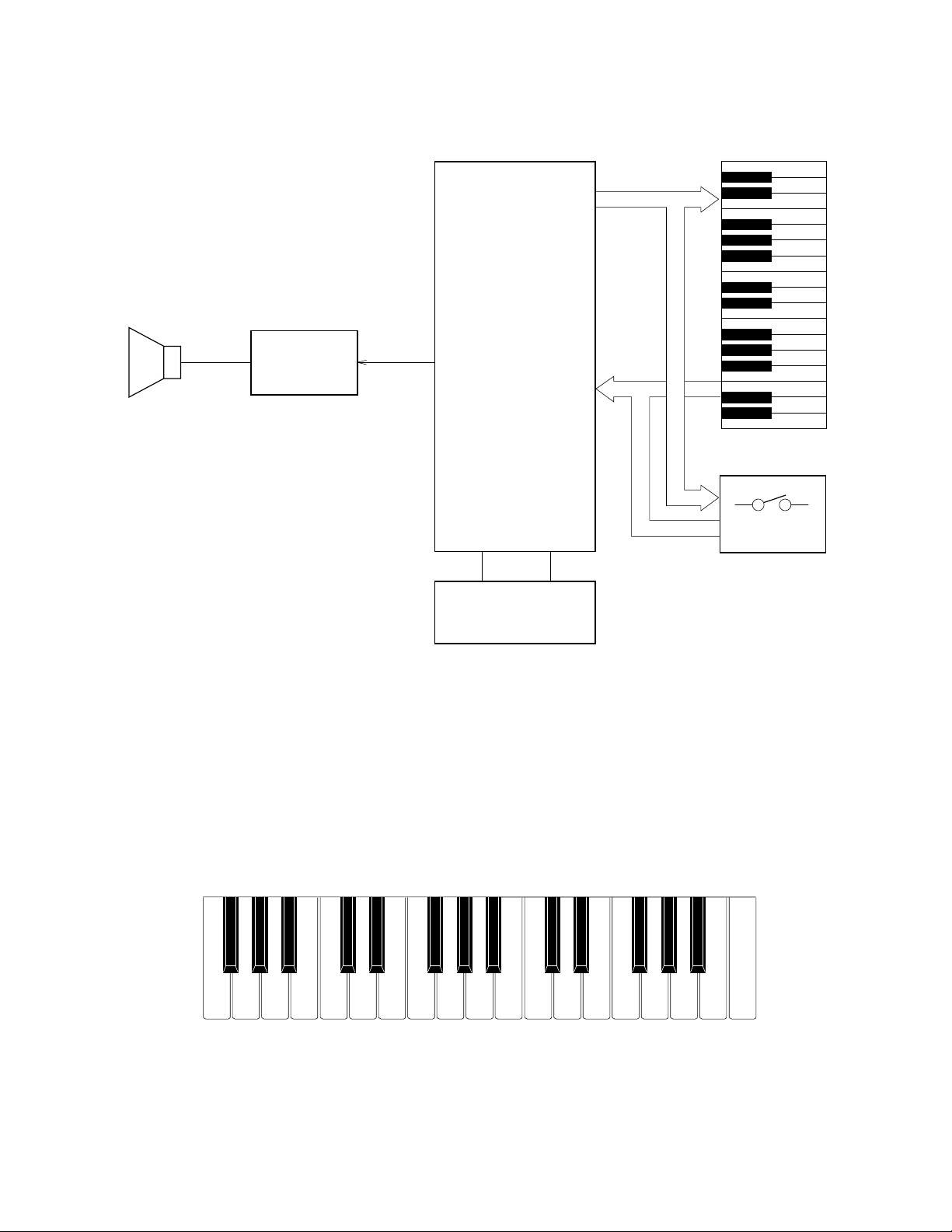
BLOCK DIAGRAM
CPU
KO0~KO6
Speaker
Amplifier
AN8053N
IC1
MSM6387-03
KI0~KI7
LSI1
Keyboard
Switches
Oscillator
X1
Nomenclature of Keys
F#3 G#3 A#3 C#4 D#4 F#4 G#4 A#4 C#5 D#5 F#5 G#5 A#5
F3 G3 A3 B3 C4 D4 E4 F4 G4 A4 B4 C5 D5 E5 F5 G5 A5 B5 C6
— 2 —
Page 5
CIRCUIT DESCRIPTION
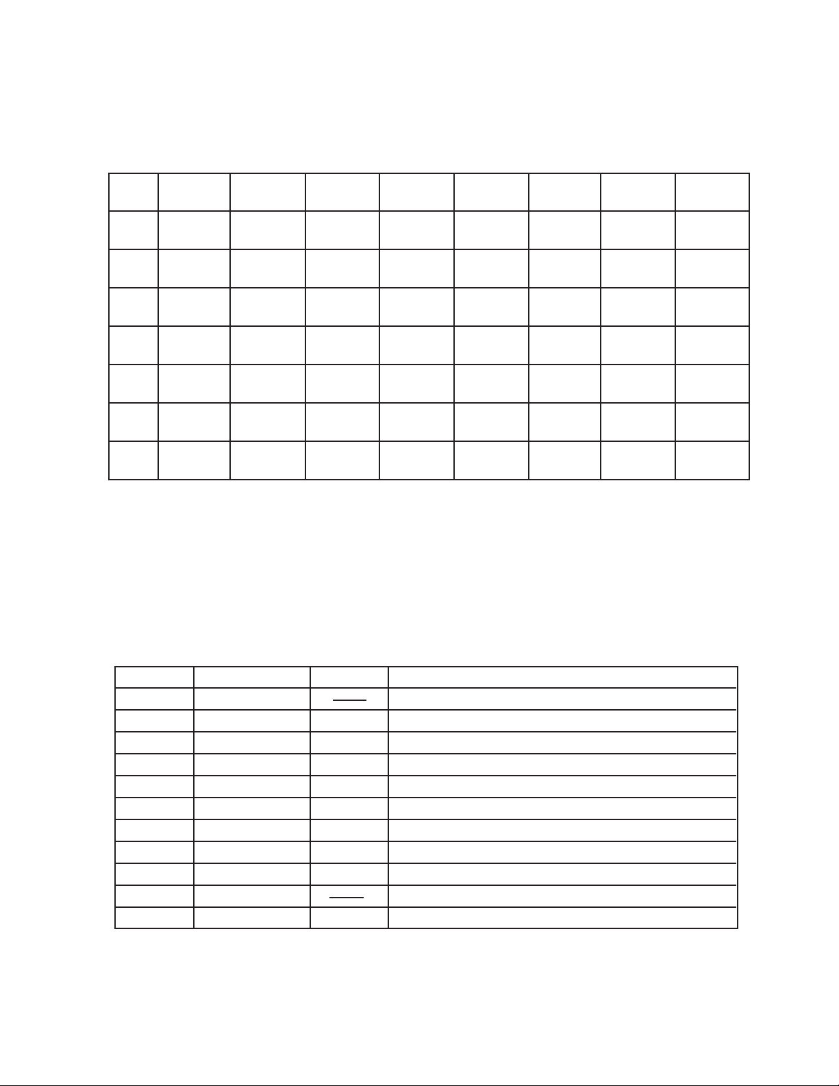
Key Matrix
KI0 KI1 KI2 KI3 KI4 KI5 KI6 KI7
KO0 F3 F#3 G3 G#3 A3 A#3 B3 C4
KO1 C#4 D4 D#4 E4 F4 F#4 G4 G#4
KO2 A4 A#4 B4 C5 C#5 D5 D#5 E5
KO3 F5 F#5 G5 G#5 A5 A#5 B5 C6
KO4 Tone 0 Tone 1 Tone 2 Tone 3 Tone 4 Select
KO5 Tone 5 Tone 6 Tone 7 Tone 8 Tone 9 Stop
KO6 Demo
CPU (LSI1: MSM6387-03)
Containing a sound data ROM and a DAC (Digital to Analog Convertor), the CPU provides sound waveform in accordance with the pressed key and the selected tone.
The following table shows the pin functions of LSI1.
Pin No. Terminal In/ Out Function
1, 2 TEST1, TEST2 Not used. Connected to ground.
3 RESET In Power ON reset input. On: +6 V Off: 0 V
4 AVDD In +5 V sorce for the built-in DAC
5 OUT Out Sound waveform output
6 AGND In Ground (0 V) source for the built-in DAC
7 GND In Ground (0 V) source
8, 9 COSI, COSO In/Out 21.725 MHz clock pulse input/output
10 VDD In +5 V source
11 ~ 18 KI0 ~ KI7 In Input terminal from keys and switches
19 ~ 23 KO11 ~ KO7 Not used.
24 ~ 30 KO6 ~ KO0 Out Key and switch scan signal output
Tempo
Up
Volume
Up
Tempo
Down
Volume
Down
— 3 —
Page 6

Amplifier/Voltage Regulator (IC1: AN8053N)
Consisting of an amplifier and a voltage regulator, AN8053N amplifies the sound signal from the CPU and
also provides the CPU +5V source.
The following figure shows the internal block diagram of IC1.
5V
VCC NC CONT
16
15
POWER
VREG
14 13
5V REG
12 11
SP AMP
NCNC NC PRE GND
10
-
+
9
VREF
Nature of Trouble
No sound at all
1
SPO NC SP GND PC-1 PC-2 SPI SPM VREF
32
4
5
6
7
8
TROUBLESHOOTING
Faulty Block
Power amp.
(IC: AN8053N)
Power Switch
CPU
(LSI1: MSM6387-03)
Oscillator (X1)
Pin 13 should have +5 V.
An amplified waveform should be observed at pin
1.
Voltage at pin 3 of the CPU should be raised from
0V to +5 V when the power switch is turned on.
Switch contact.
Pins 24 ~ 30 should provide pulses.
Pin 5 should provide a sound waveform when a
key is pressed.
Pins 8 and 9 of the CPU should receive an oscil-
lation signal.
Checkpoint
Certain key(s) or
switch(es) do(es) not
work.
Key or Switch Contact
Open Circuit on KO or KI
Lines
— 4 —
Page 7

M3205-MA1M PCB
PCB VIEW and MAJOR WAVEFORMS
1
3
4
5
2
Clock pulse COSO
MSM6387-03 Pin 9
Key scan signal KO0
MSM6387-03 Pin 30
Key scan signal KO1
MSM6387-03 Pin 29
— 5 —
Sound output
MSM6387-03 Pin 5
Tone : Piano
Key : G4
Power Amp. output
AN8053N Pin 1
Tone : Piano
Key : G4
Volume : Max.
Page 8

1
2
3
4
5
6.0
0.5
0.5
0.5
0.5
0.5
0.5
0.5
5.2
4.8
2.5
2.2
2.2
4.9
0.0
0.0
0.0
0.0
5.2
0.0
0.0
3.9
3.1
4.0
4.0
M3210-MA1M PCB
SCHEMATIC DIAGRAM
— 6 —
Page 9

IC LEAD IDENTIFICATION
LSI1: MSM6387-03
30292824272625
KO0
KO1
KO2
KO3
KO4
KO5
TEST2
TEST1
RESET
AVDD
OUT
AGND
1
2
374
5
6
IC1: AN8053N
16
15
14
23222120191817
KO6
KO7
KO8
KO9
KO10
GND
COSI
COSO
VDD
KI0
8
9
1011121314
13
12
11
10
KI7
KO11
KI1
KI2
9
KI6
KI3
16
KI5
KI4
15
NC
VCC
SPONCSPG
1
CONT
2
3
NC
VREG
PC-1
PC-2
4
5
NC
SPI
6
NC
SPM
7
PR GND
VREF
8
— 7 —
Page 10

7
EXPLODED VIEW
A
2
3
8
9
0
4
5
6
1
D
C
B
— 8 —
Page 11
PARTS LIST
PK-5
Notes: 1. Prices and specifications are subject to change with-
out prior notice.
2. As for spare parts order and supply, refer to the
"GUIDEBOOK for Spare parts Supply", published
seperately.
3. The numbers in item column correspond to the same
numbers in drawing.
Page 12

FOB Japan
N Item Code No. Parts Name Specification Q M N.R.Yen R *
Unit Price
Electrical Parts
C1/2 2807 1531 Electrolytic capacitor 10RE3-470-T2-T 2 20 C A
C3/4 2807 6392 Electrolytic capacitor 10RE3-22-T2-T 2 20 C A
C5 2813 1771 Semiconductive capacitor DD405SR393K16-T 1 10 C A
C6 2807 6378 Electrolytic capacitor 50RE3-1-T2-T 1 20 C A
C7 2801 9100 Electrolytic capacitor 6.3RE3-100-T2-T 1 20 C A
C8 2801 9660 Electrolytic capacitor 6.3RE3-220-T2-T 1 20 C A
D1 2301 0241 Diode 1SS254T-77-T 1 20 C A
FB1/2 3035 0266 Ferrite beads BL02RN2-R62T4-T 2 10 C A
N IC1 2114 3269 IC AN8053N 1 1 A B
LSI1 2010 8260 LSI MSM6387-03SS-106 1 1 A I
R3 2606 1141 Carbon film resistor R-20-1K-J-T23-T 1 20 C A
R4 2606 1554 Carbon film resistor R-20-120K-J-T23-T 1 20 C A
R5 2606 1239 Carbon film resistor R-20-8.2K-J-T23-T 1 20 C A
R6 2606 1274 Carbon film resistor R-20-1.5K-J-T23-T 1 20 C A
R7 2606 1169 Carbon film resistor R-20-100-J-T23-T 1 20 C A
X1 2590 0742 Ceramic oscillator EFO-GC2175C3 1 1 A B
4317 4031 Blank PCB M3205-MA1M M111705A-1 1 1 C B
6917 1762 Battery spring (+) M410913B-1 1 20 B A
6921 6211 Battery spring (-) M412171A-1 1 20 B A
1 PCB ass'y M3205-MA1M M211679*1 1 1 B
Mechanical Parts
2 3831 0525 Speaker KUE-65RGF02A 1 1 B C
3 6909 7380 SL contact 09D CSB-09D 1 20 B A
4 6917 1571 White key set M210 M210610A-1 1 5 A B
5 6917 1580 Black key set M210 M210609-1 1 10 A A
6 6917 1591 Contact rubber M210 M210605A-1 1 5 B B
7 6917 1610 Slide knob 210 M310807-1 1 20 C A
8 6917 1630 Button 210A M310824-1 1 20 B A
9 6917 1640 Button 210B M310825-1 1 10 B A
N 10 6917 1730 Button 210B M310825-2 1 5 B B
N 11 Top case 205B M111690-2 1 1 C
N 12 Bottom case 205B M111691-2 1 1 C
13 Screw 2.2 x 6 3 20 C
14 Screw 2.30 x 8 ZMC-3 6 20 C
The parts having a blank in their code No. column should be ordered from C.M.F.G.
Notes: N – New parts
M – Minimum order/supply quantity
R – Rank
— 9 —
Page 13

8-11-10, Nishi-Shinjuku
Shinjuku-ku, Tokyo 160, Japan
Telephone: 03-3347-4926
May, 1994
 Loading...