

Page 1

SERVICE MANUAL
& PARTS LIST
REF. NO. S/M-756
NOV. 2001
MODULE NO.
QW-2424
MSG-130D
R
(WITHOUT PRICE)
Page 2

CONTENTS
Page
1. SPECIFICATIONS: QW-2424..................................................................... 1
2. OPERATION CHART: QW-2424................................................................2
3. DRAWINGS: QW-2424
3-1. LCD DIAGRAM ...................................................................................3
3-2. CIRCUIT DIAGRAM ............................................................................ 4
3-3. CHECKING TERMINALS AND COMPONENT .................................. 5
4. EXPLODED VIEW: QW-2424.....................................................................6
5. PARTS LIST: QW-2424..............................................................................7
6. PRECAUTIONS FOR REPAIR: QW-2424
6-1. AC (ALL CLEAR) AND REMOVING OF MODULE ............................ 8
6-2. ACCURACY CHECKING .................................................................... 8
1. SPECIFICATIONS: QW-2424
Item Detail
Battery CR1620
Battery life Approx. 3 years
Current consumption 1.19 µA maximum
Alarm system Piezo plate on Back cover
Accuracy ±15 sec./month
Accuracy setting system Trimmer capacitor
Accuracy checking See page 8
Functions • Shock resistant
• Multi Illuminator (Multi-color LED backlight)
Afterglow
• 1/100-second stopwatch
Measuring capacity: 23:59'59.99"
Measuring modes: Elapsed time, split time, 1st-2nd place times
Other: Auto-start
• Daily alarm
• Hourly time signal
• Auto-calendar (to year 2039)
• 12/24-hour formats
•Regular timekeeping: Hr, min, sec, am/pm, month, date, day, daylight
saving on/off
— 1 —
Page 3
2. OPERATION CHART: QW-2424
General Guide
• Press B to change from mode to mode.
Timekeeping Mode Alarm Mode Stopwatch Mode
Press .
To turn the Daily Alarm and Hourly Time Signal on and off
Press C while in the Alarm Mode to change the status of the Daily Alarm and
Hourly Time Signal in the following sequence.
Both OFFBoth ON
To test the alarm
Hold down C while in the Alarm Mode to sound the alarm.
Daily Alarm
only
Hourly Time
Signal only
Timekeeping Mode
Year
Day of week
Seconds
Hour : Minutes
Hour
Minutes
Month - Day
PM indicator
DST on indicator
• In the Timekeeping Mode, press C to switch between the 12-hour and 24-
hour format.
• When the 12-hour format is selected, “p.m.” times are indicated on the display
by P, while “a.m.” times are indicated b y A. No indicators are used with the
24-hour format.
To set the time and date
1.Hold down A until the second’s digits start to flash.
2.Press B to move the selection around the display in the following sequence.
Seconds
Day
3.While the second’s digits are selected (flashing), press C to reset them to
00. If you press C while the second’s count is in the range of 30 to 59, they
are reset to 00 and 1 is added to the minutes. If the second’s count is in the
range of 00 to 29, the minute’s count is unchanged.
4.While the DST* setting is selected (DST on indicator is flashing), press C to
toggle it on (on) and off (OF).
5.While any other setting (besides seconds) is selected (flashing), press C to
change it. Holding down C changes the digits at high speed.
• The date can be set with the range of January 1, 2000 to December 31,
2039.
6.After you set the time and date, press A to return to the Timekeeping Mode.
• If you do not operate any button for a few minutes while a selection is
flashing, the flashing stops and the watch goes back to the Timekeeping
Mode automatically.
• The day of the week is automatically set in accordance with the date.
• The watch’s built-in full automatic calendar automatically makes allowances
for different month lengths and leap years. Once you set the date, there
should be no reason to change it except after the replacement of the watch’s
battery.
Da* ylight Saving Time (DST), which is also sometimes called
“summer time” advances the time for one hour, as is the custom in some
areas during the summer. Remember that not all countries or even local areas
use Daylight Saving Time.
DST on/off
Month
About the Multi Illuminator Backlight
• In any mode, press L to illuminate the display for about 3 seconds.
• The backlight of this watch employs a “Multi Illuminator” light, which
illuminates the display using one of three colors.
• The color of the backlight changes according to function.
• Frequent use of the backlight shortens the battery life.
• The illumination provided by the backlight may be hard to see when viewed
under direct sunlight.
• The backlight automatically turns off whenever an alarm sounds.
Stopwatch Mode
Mode
1/100
indicator
second
Hours
Minutes
(a) Elapsed time measurement
Start
(b) Split time measurement
Start
(c) Split time and 1st-2nd place times
Start
About the Auto-Start function
With the Auto-Start function, the watch performs a 5-second countdown. When
the countdown reaches zero, stopwatch operation starts automatically. During
the final three seconds of the countdown, a beeper sounds with each second.
To turn the Auto-Start function on and off
While the display is showing all zeros in the Stopwatch Mode, press A to toggle
it on and off.
• To stop the Auto-Start countdown and return to the all-zero display, press A.
• Pressing C while the Auto-Start countdown is in progress immediately starts
the stopwatch.
The Stopwatch Mode lets you measure elapsed time,
split times, and two finishes. The range of the
stopwatch is 23 hours 59 minutes, 59.99 seconds.
• If you do not operate any button for a few minutes
while the all-zero screen is on the display in the
Stopwatch Mode, the watch goes back to the
Timekeeping Mode automatically.
Seconds
Stop Re-start Stop Clear
Split Split release Stop Clear
Split Stop Split release Clear
First runner
finishes.
Press .
Second runner
finishes.
Record time of
first runner.
Auto start ONAuto start OFF
Record time of
second runner.
AUTO START
indicator
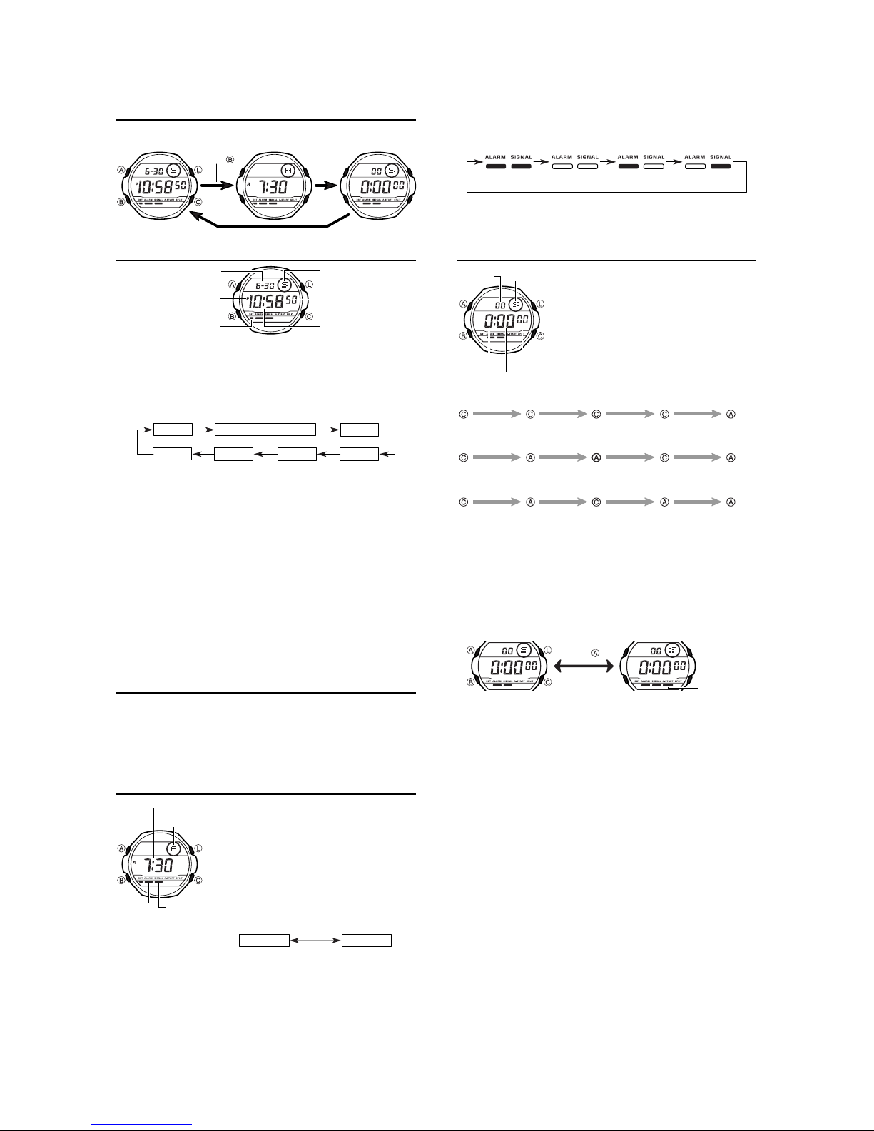
Alarm Mode
Hour : Minutes
Mode
indicator
Alarm on
indicator
3.Press C to increase the number. Holding down C changes the digits at
• The format (12-hour and 24-hour) of the alarm time matches the format you
select for normal timekeeping.
• When setting the alarm time using the 12-hour format, take care to set the
time correctly as morning or afternoon.
4.After you set the alarm time, press A to return to the Alarm Mode.
• If you do not operate any button for a few minutes while a selection is
flashing, the flashing stops and the watch goes back to the Alarm Mode
automatically.
To stop the alarm
• Press any button to stop the alarm after it starts to sound.
high speed.
Hourly time
signal on
indicator
When the Daily Alarm is turned on, an alarm sounds
for 20 seconds at the preset time each day. When
the Hourly Time Signal is turned on, the watch beeps
every hour on the hour.
• If you do not operate any button for a few minutes
while in the Alarm Mode, the watch goes back to
the Timekeeping Mode automatically.
To set the alarm time
1.Hold down A until the hour digits start to flash on
the display. The hour digits flash because they are
selected
. At this time the Alarm is automatically
turned on.
2.Press B to change the selection in the following
sequence.
Hour Minutes
— 2 —
Page 4

3. DRAWINGS: QW-2424
3-1. LCD DIAGRAM
L 1
L 2
L 3
L 4
L 5
L 6
L 7
L 8
L 9
L10
L11
LC1
LC2
LC3
LC4
LC5
a d e g 5
AM PM
a9
a8
b8
f8
g8
e8
h5
f4
b5
i5
c5
j5
DST1 ALM SIG AUTO-ST SPL
g4
e4
d4
h y p
c8
d8
h4
a4
b4
i4
c4
j4
col0
col1
a7
f7
g7
e7
d7
e3
a6
b6
f6
b7
g6
e6
c7
f3
g3
d3
c6
d6
h3
a3
b3
i3
c3
j3
Y6
Y5
Y4
Y3
Y2
Y1
Y0
h2
a2
f2
g2
e2
d2
b2
i2
c2
j2
X6X0 X1X2X3X4X5
a1
f1
g1
e1
d1
a0
b1
c1
b0
f0
g0
e0
c0
d0
SEG.
L 1
L 2
L 3
L 4
L 5
L 6
L 7
L 8
L 9
L10
L11
L12
L13
COM.
LC1
c6
d6
e6
X0Y6
X1Y6
X2Y6
X3Y6
X4Y6
X5Y6
X6Y6
X6Y0
X5Y0
LC2
b6
g6
f6
a6
X0Y2
X1Y2
X2Y2
X3Y2
X4Y2
X5Y2
X6Y2
X6Y1
X5Y1
LC3
c8
e7
d7
c7
X0Y3
X1Y3
X2Y3
X3Y3
X4Y3
X5Y3
X6Y3
AUTO-ST
c0
LC4
g8
hyp
g7
b7
X0Y4
X1Y4
X2Y4
X3Y4
X4Y4
X5Y4
X6Y4
SPL
b0
LC5
a8
b8
f7
a7
X0Y5
X1Y5
X2Y5
X3Y5
X4Y5
X5Y5
X6Y5
a0
L27
L26
SEG.
L25
L14
L15
L16
L17
L18
L19
L20
L21
L22
L23
L24
L25
L26
L27
L24
COM.
L23
L22
X4Y0
X3Y0
X2Y0
X1Y0
X0Y0
(DST2)
L21
LC1
j2
d2
j3
d3
j4
d4
j5
PM
L20
L19
L18
X4Y1
X3Y1
X2Y1
X1Y1
X0Y1
L17
LC2
c2
e2
c3
e3
c4
e4
c5
AM
a9
L16
L15
L14
LC3
d0
e0
c1
SIG
i2
g2
i3
g3
i4
g4
i5
adeg5
d8
L13
L12
LC4
g0
b1
g1
d1
ALM
b2
f2
b3
f3
b4
f4
b5
col0
e8
LC5
f0
a1
f1
e1
DST1
h2
a2
h3
a3
h4
a4
h5
col1
f8
— 3 —
Page 5

3-2. CIRCUIT DIAGRAM
LCD
CT
Xtal
LED1
R3
Tr4
T
AC
VDD
XTB
XT
N1
N2
N3
N4
LD1
LD2
LD3
C5
1
24
R1
Tr2
LC1 - - - - - LC5
VSS2
BAT
3
R2
Tr3
L1 - - - - - - - L27
LSI
TOTAL 59PINS
BONDING 59PINS
LED2
✽4
VSS1
C2
C3C4
C1
✽ 1.Short (Soldering)
✽ 2.SA is not used in this module.
✽ 3.Inclination switch
✽ 4.No mounted in this module.
VCH VSS3 VC1 VC2
KI6
KI7
KI8
KI1
KI2
KI3
KI4
KI5
BD
Tr1
L
PZ
KI6: Open
KI7: Open
KI8: Open
No mounted in this module.
✽1
✽1
✽1
KS
S1
S2
S3
S4
SA
✽3
✽2
— 4 —
Page 6

3-3. CHECKING TERMINALS AND COMPONENT
Capacitor/Chip
C1
Capacitor/Chip
C4
Capacitor/Chip
C5
Capacitor/Chip
C3
KI2 KI4
KI8
VDD
VDD
N1
VDD
N2
VDD
N3
VDD
N4
VDD
KI7
KI7
LD2
VDD
2. PCB ASS'Y
(7640 4807)
KI6
5
R2
VDD
4
5
2
VDD
KI5
3
Capacitor/Chip
C2
7. Cushion/6
(7211 0064)
4. Oscillator/Crystal
Xtal
(7110 0693)
CT
3. Capacitor/Trimmer
(1001 0950)
VSS3
VDD
KI4
VDD
VSS2
VDD
VDD
VCH
KI5
VC1
VC2
KI1KI3
KI1
VCH
VC1
VSS2
KI7
LD2
VDD
VDD
VSS2
VSS2
KI7
BD
VDD
L
VSS2 VSS2LD2
R3
R3 R2 R1342
KI5
L
L
L
VDD
XT
KI2
XTB
XT
AC
LD3
LD2
LD1
VSS1
VDD
VSS2
LD3
LD1
R2
R3
R1
R2
KI3
R1
Tr2
Transistor
Tr1
Transistor
Coil
L
6. Cushion/506
(7211 9631)
Tr4
Resistor/Chip
R3
Tr3
Resistor/Chip
R2
Transistor
Resistor/Chip
R1
Transistor
Top view of P.C.B. ass'y Bottom view of P.C.B. ass'y
— 5 —
Page 7

4. EXPLODED VIEW: QW-2424
13 (1006 0076)
14 (1006 0077)
15 (1006 0078)
1 (1006 0073)
9 (1006 0074)
10 (1006 0075)
12 (1006 0071)
2 (7640 4807)
17 (7230 0511)
8 (1006 0069)
19 (1006 0070)
5 (1002 7903)
16 (7233 2629)
18 (7230 0980)
Battery Lithium
(CR1620)
11 (1005 3573)
— 6 —
Page 8

5. PARTS LIST: QW-2424
-
-
-
p
yp
p
p
Note: 1. Prices and specifications are subject to change without prior notice.
2. Spare parts are classified as follows according to their importance in after-sales service.
A Rank -------------------------------------B Rank -------------------------------------C Rank --------------------------------------
3. Batteries in Bulk pack on the tray will be supplied from our Overseas Spare Parts Section under charge basis.
Batteries in Blister pack will be supplied from our Sales Department.
4. As for order/supply of spare parts, refer to the separate publication "GUIDE BOOK for spare parts supply".
Very Important
Important
Less important
Item Code No. Parts Name S
MODULE/WITHOUT MOVEMENT QW-2424AT-02 MSG-130V-2V/MSG-130D-2V 1
MODULE/WITHOUT MOVEMENT QW-2424AT-03 MSG-130V-4V/MSG-130D-5V 1
MODULE/WITHOUT MOVEMENT QW-2424AT-05 MSG-130V-8V 1
< The module QW-2424 is "built-in t
therefore the module as the s
1 1006 0073 LCD S2424-01TTP QW-2424AT Common 1 A
2 7640 4807 PCB ASS'Y Q255299*1TK QW-2424AT Common 1 A
3 1001 0950 CAPACITOR/TRIMMER CTZ2E-30C-W2-P QW-2424AT Common 1 B
4 7110 0693 OSCILLATOR/CRYSTAL DT-26SJ QW-2424AT Common 1 B
5 1002 7903 CONTACT/BATTERY(-) Q39603B-1 QW-2424AT Common 1 C
6 7211 9631 CUSHION/506 Q49364-1 QW-2424AT Common 1 C
7 7211 0064 CUSHION/6 Q4914-1 QW-2424AT Common 1 C
8 1006 0069 HOUSING Q152181-1 QW-2424AT Common 1 C
9 1006 0074 INTERCONNECTOR 2424-1 Q468551-1 QW-2424AT Common 1 C
10 1006 0075 INTERCONNECTOR 2424-2 Q468552-1 QW-2424AT Common 1 C
11 1005 3573 LABEL Q468079-1 QW-2424AT Common 1 C
12 1006 0071 LIGHT GUIDE Q255212A-1 QW-2424AT Common 1 C
13 1006 0076 PANEL Q369962-2 QW-2424AT-02TK 1 C
14 1006 0077 PANEL Q369962-3 QW-2424AT-03TK 1 C
15 1006 0078 PANEL Q369962-4 QW-2424AT-05TK 1 C
16 7233 2629 SHEET/INSULATION Q461568-1 QW-2424AT Common 1 C
17 7230 0511 SPRING/COIL 1253-2 Q439219-1 QW-2424AT Common 1 B
18 7230 0980 SPRING/COIL 1514 Q456768-1 QW-2424AT Common 1 B
19 1006 0070 SUPPORTER/PCB ASS'Y Q152182-1 QW-2424AT Common 1 C
BATTERY/LITHIUM CR1620 QW-2424AT Common 1
are parts is not available. >
ecification Applicable Q R
e" which is assembled directly to the case,
For the
Notes: Q - Used quantity
rices and minimum order/supply quantities of the above parts, refer to the Parts Price List P.P.L.-576.
R - Rank
— 7 —
Page 9

6. PRECAUTIONS FOR REPAIR: QW-2424
6-1. AC (ALL CLEAR) AND REMOVING OF MODULE
1. Perform AC (ALL CLEAR) when inserting a new battery, or else the memories and/ or counters may give
erratic displays.
Touch the AC contact and the negative (–) side of the main plate with the metallic tweezers.
The contact should be made for about two seconds.
2. On removing of the module from the case, please insert the precision screw driver between the module
and the case pointed by arrows.
Metallic tweezers
6-2. ACCURACY CHECKING
Check the accuracy of the module with the quartz timer after switching the module to “ACCURACY
CHECKING MODE”.
The operations are shown below:
A) SWITCHING TO “ACCURACY CHECKING MODE”
While pressing D button, press A and C buttons at the normal time keeping mode.
Then all the segments are displayed and the LCD drive signals are changed to the static drive signal
of “32 Hz” so that you can check the accuracy with the quartz timer.
B) CANCELLATION OF THE “ACCURACY CHECKING MODE”
Push any button except for D button.
Then the display is returned to its original state.
NOTE: The “ACCURACY CHECKING MODE” will automatically return
to the regular mode in 1 ~ 2 hour(s) without any operation.
— 8 —
A
B
QW-2424
L
C
Page 10

CASIO TECHNO CO.,LTD.
Overseas Service Division
Nishi-Shinjuku Kimuraya Bldg. 1F
5-25, Nishi-Shinjuku 7-Chome
Shinjuku-ku, Tokyo 160-0023, Japan
 Loading...