

Page 1
ML-3
POPS
ROCK
1
2 3 4 5
8 BEAT
16 BEAT
MODE
POWER OFF
DISCO
11 PIANO
12 ELEC PIANO
13 PIPE ORGAN
14 JAZZ ORGAN
15 ACCORDION
21 FLUTE
22 CLARINET
23 TRUMPET
24 HARMONICA
ANY-KEY PLAY
PLAY
SLOW ROCK
6
DEMO
MELODY GUIDE
25 VIOLIN
31 BRASS ENS
32 SYNTH-BRASS
33 STRINGS
34 SYNTH-STRINGS
35 CHORUS
41 ELEC GUITAR
42 JAZZ GUITAR
43 VIBRAPHONE
FUNK
7
SWING
8
44 CHURCH BELLS
45 BELLS
51 SYNTH-REED
52 WAW VOICE
53 METAL LEAD
54 ROCK DRUM
55 S.E.
VOLUME
BOSSA NOVA
9
ELECTRONIC KEYBOARD
SONG BANK25 TONES
1 FRÈRE JACQUES
2 JOY TO THE WORLD
3 OLD MacDONALD HAD A FARM
4 TWINKLE TWINKLE LITTLE STAR
5 MINUET(J.S.BACH )
6 LONDON BRIDGE
7 MICHAEL
8 MARY HAD A LITTLE LAMB
9 THE CAMPTOWN RACES
10 ODE TO JOY
TEMPO
SAMBA
10
MARCH
RHYTHM
SEL.
WALTZ
STOP
34
2
1
TONE
5
LIGHT ON/OFF
RHYTHM
SONG
1
10
ML-3
Page 2

CONTENTS
Specifications . . . . . . . . . . . . . . . . . . . . . . . . . . . . . . . . . . . . . . . . 1
Block Diagram . . . . . . . . . . . . . . . . . . . . . . . . . . . . . . . . . . . . . . . . 2
Circuit Description . . . . . . . . . . . . . . . . . . . . . . . . . . . . . . . . . . . . 3
Troubleshooting . . . . . . . . . . . . . . . . . . . . . . . . . . . . . . . . . . . . . . 5
Schematic Diagrams. . . . . . . . . . . . . . . . . . . . . . . . . . . . . . . . . . . 6
PCB View and Major Waveforms. . . . . . . . . . . . . . . . . . . . . . . . . 9
Exploded View. . . . . . . . . . . . . . . . . . . . . . . . . . . . . . . . . . . . . . . 10
Parts List . . . . . . . . . . . . . . . . . . . . . . . . . . . . . . . . . . . . . . . . . . . 11
Page 3

SPECIFICATIONS
General
Number of Keys: 32
Illuminated Keys: White and Black keys
Polyphonic: 2-note
Preset Tones: 25
Auto-Rhythms: 12
Demonstration Tunes: 10
Lesson Functions: 3 modes; Demo, Any-Key Play, Melody Guide
Built-In Speaker: 8.0 cm dia. 1.0 W Input Rating: 1 pce.
Terminals: Mic. Jack [Input Impedance: 20 kΩ
AC Adapter Jack (DC 7.5 V)
Power Source: DC: 5 AA size dry batteries
Battery life: Approx. 4 hours (SUM-3/R6P)
AC: AC adapter AD-1
Power ON Reminder*: 3 minutes after the last operation
Power Consumption: 1.5 W
Dimensions: 57 × 412 × 208 mm (HWD)
(2-1/4 × 16-3/8 × 8-1/4 inches) (HWD)
Weight: 0.95 kg (2.1 lbs) excluding batteries
Electrical
Current Drain with 7.5 V DC:
No Sound Output 44 mA ± 20%
Maximum Volume 280 mA ± 20%
with keys B3 and C4 pressed in Flute tone
Volume: Maximum, Rhythm: Rock,
Tempo: Maximum, Mic. input: 29 mV
Speaker Input Level (Vrms with 4 Ω load): 740 mV ± 20%
with key C4 pressed in Flute tone
Volume: Maximum
Minimum Operating Voltage: 6.2 V
*Power ON Reminder
Power ON reminder is sudden audible and light signals, a short melody at maximum volume and lighting
up the illuminated keyboard for a few seconds.
Power ON reminder functions three minutes after the last operation, and it repeats every three minutes until
turning the switch off or restarting operations.
— 1 —
Page 4
Mic. input
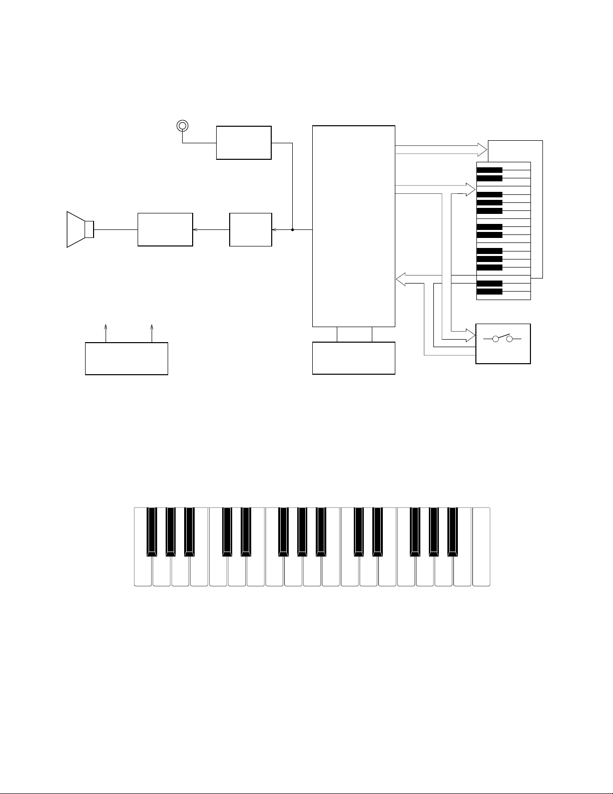
BLOCK DIAGRAM
Mic. amp.
T4, T5
CPU
LX0~LX3
LY0~LY7
KO0~KO11
Illuminated Keyboard
LEDs
Amplifier
AN8053N
IC1
Speaker
VDD 5.6V
Power Supply Circuit
AVDD 5.6V
T1, D3
Nomenclature of Keys
F#3 G#3 A#3 C#4 D#4 F#4 G#4 A#4 C#5 D#5 F#5 G#5 A#5
Filter
T3
MSM6521-13
LSI1
Oscillator
XL1
KI0~KI7
Switches
F3 G3 A3 B3 C4 D4 E4 F4 G4 A4 B4 C5 D5 E5 F5 G5 A5 B5 C6
— 2 —
Page 5
CIRCUIT DESCRIPTION
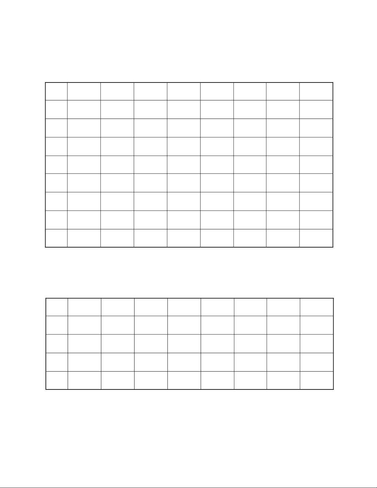
Key Matrix
KI0 KI1 KI2 KI3 KI4 KI5 KI6 KI7
KO0 F3 F#3 G3 G#3 A3 A#3 B3 C4
KO1 C#4 D4 D#4 E4 F4 F#4 G4 G#4
KO2 A4 A#4 B4 C5 C#5 D5 D#5 E5
KO3 F5 F#5 G5 G#5 A5 A#5 B5 C6
KO4
KO5 Tone 1
KO6 Tone 2 Tone 3 Tone 4 Tone 5
KO7
Melody
Guide
Any Key
Play
Volume
Down
Rhythm
Stop
Demo Play
Volume
Up
Tempo
Down
Rhythm
Select
Keyboard LED Matrix
LY0 LY1 LY2 LY3 LY4 LY5 LY6 LY7
LX0 C6 F5 E5 A4 G#4 C#4 C4 F3
LX1 B5 F#5 D#5 A#4 G4 D4 B3 F#3
Light
On/Off
Tempo
Up
LX2 A#5 G5 D5 B4 F#4 D#4 A#3 G3
LX3 A5 G#5 C#5 C5 F4 E4 A3 G#3
— 3 —
Page 6

CPU (LSI1: MSM6521-13)
Containing a sound data ROM and a DAC (Digital to Analog Converter), the CPU provides sound waveform
in accordance with the pressed key and selected tone. The CPU also drives LEDs in the illuminated keyboard
directly. The following table shows the pin functions of LSI1.
Pin No. Terminal In/Out Function
1 ~ 7 LY1 ~ LY7 Out Keyboard LED drive signal output
8 LVDD1 In +5 V source for the built-in LED driver
9 LGND2 In Ground (0 V) source for the built-in LED driver
10 ~ 13 LX0 ~ LX3 Out Keyboard LED drive signal output
14 ~ 17 LX4 ~ LX7 Out Not used.
18 LVDD2 In +5 V source for the built-in LED driver
19 GND2 In Ground (0 V) source
20, 21 COSI, COSO In/Out 21.725 MHz clock pulse input/output
22 VDD In +5 V source
23 GND1 In Ground (0 V) source
24 ~ 26 TEST1 ~ TEST3 In Not used. Connected to ground.
27 RESET In Reset signal input. Power OFF: 0 V, Power ON: +5 V
28 AVDD In +5 V source for the built-in DAC
29 OUT Out Sound waveform output
30 AGND In Ground (0 V) source for the built-in DAC
31 ~ 38 KI0 ~ KI7 In Input terminal for keys and switches
39 ~ 46 KO0 ~ KO7 Out Key and switch scan signal input
47 ~ 58 — — Not used.
59 LGND1 In Ground (0 V) source for the built-in LED driver
60 LY0 In Keyboard LED drive signal output
Filter Block
Since the sound signal from the CPU is a stepped waveform, the filter block is added to smooth the waveform.
AVDD
T2
2SC1740SQ
C9
R11
AG
C10
AG
— 4 —
R12
C11
R13
R14
C12
AG
Page 7

Power Supply Circuit
The power supply circuit regulates a constant output voltage +5.6V by T1 and D4.
T1
2SD1858Q,R
R1
D3
MTZJ6.8A
C3
R2
R5
R3 R4
R6
C4
DGGND
VDD +5.6V
D5
AVDD +5.6V
C5
AG
DC +7.5 V
Input
D2
Power Switch
ON
OFF
GND
TROUBLESHOOTING
Nature of Trouble Faulty Block Checkpoint
No power Power Supply Circuit Base of T1 should receive +6 V.
Emitter of T1 should provide +5.6 V.
Power switch Switch contact.
Power Jack (J1) Jack contact.
No sound at all Power Amp.
(IC1: AN8053N)
CPU (LSI1: MSM6521-13) Voltage at pin 27 should rise 0 V to 5.6
Oscillator (XL1) Pins 20 and 21 of the CPU should
Keyboard LEDs don't
light up
A certain key or switch
Keyboard LED
Keyboard LED Matrix Open circuit on LX or LY line.
Key and Switch Matrix Dust on the contact.
does not function
Certain keys or switches
Key and Switch Matrix Open circuit on KC or KI line.
do not function
Pin 16 should receive +7.5 V when the
power switch is turned on.
Voltage at pin 14 should drop at 0 V
when the power switch is turned on.
Check output signal of pin 1.
V when the power switch is turned on.
Pins 39 ~ 46 should provide pulses.
Pin 29 should have a sound signal when
a key is pressed.
receive an ocsillation signal.
— 5 —
Page 8

JCM605-KY1M
SCHEMATIC DIAGRAMS
— 6 —
Page 9

JCM605-LD2MJCM605-LD1M
— 7 —
Page 10

JCM607-MA1M/MA2M
5
6
5
4
6
1
2
3
— 8 —
Page 11
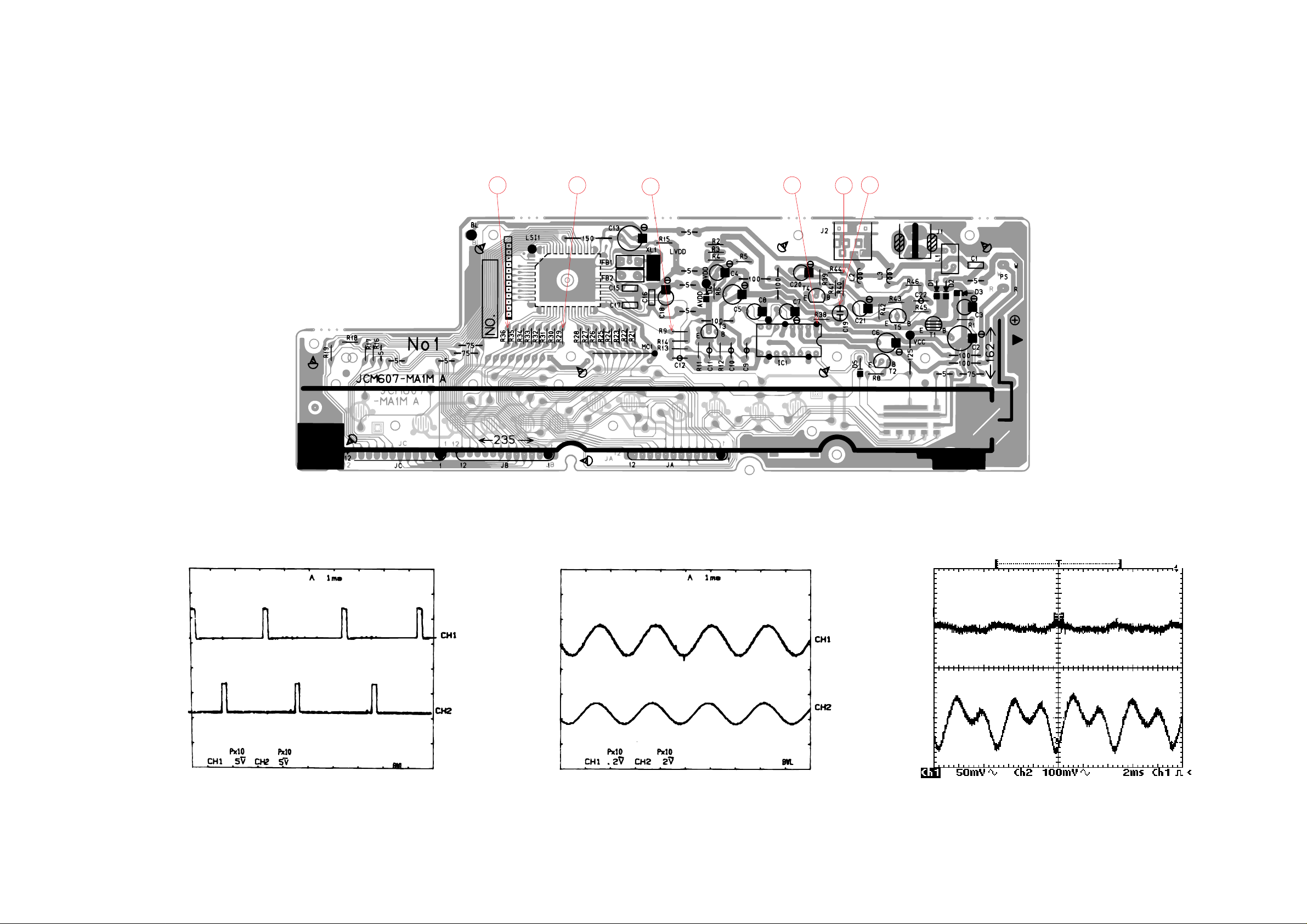
PCB VIEW AND MAJOR WAVEFORMS
2 1
3
4
6
5
1
2
1
Key scan signal KO0
MSM6521-13 pin39
2
Key scan signal KO7
MSM6521-13 pin46
3
4
3
Sound signal output
MSM6521-13 pin29
4
Power amp output
AN8053N pin 1
5
6
5 Mic, amp. input
6 Mic. amp. output
T4 Emitter
— 9 —
Page 12

EXPLODED VIEW
8
7
6
5
R-1
R-2
9
10
1
11
4
3
2
R-3
12
— 10 —
Page 13

PARTS LIST
ML-3
Notes: This parts list does not include the cosmetic parts, which
parts are marked with item No. "R-X" in the exploded
view.
Contact our spare parts department if you need these
parts for refurbish.
1. Prices and specifications are subject to change without prior notice.
2. As for spare parts order and supply, refer to the
"GUIDEBOOK for Spare parts Supply", published
seperately.
3. The numbers in item column correspond to the same
numbers in drawing.
Page 14

Item Code No. Parts Name Specification Q R
Main PCB
1 6922 8720 Main PCB ass'y M607MA1,2M M111832*1 1 B
LSI1 2011 8057 LSI MSM6521-13 1 A
IC1 2114 3269 IC AN8053N 1 A
T1 2253 0448 Transistor 2SD1858Q,R-TV6-T 1 A
T2 - T5 2220 1387 Transistor 2SC1740SQ-TP-T 4 B
D1 2390 0371 Diode DSK10B-BT-T 1 B
D2 2390 1323 Diode RB100A-T32-T 1 B
D3 2360 1519 Zener diode MTZJ6.8A-T77-T 1 A
D4/5 2390 1344 Diode 1SS133T-77-T 2 B
XL1 2590 0742 Ceramic oscillator EFO-GC2175C3 1 B
J1 3501 3731 Power jack HEC2305-01-250 1 A
J2 3501 4382 Jack HSJ2000-01-010
1
LED PCBs
2 6922 6890 LED PCB ass'y M605-LM1M M211795*1 1 C
2370 1043 LED KR3301X-J171K 19 B
3 6922 6900 LED PCB ass'y M605-LM2M M211796*1 1 C
2370 1050 LED KR3302X-J173K
13
Mechanical Parts
4
4317 5081 Blank PCB JCM605-KY1 M211780A-1
1
5 3831 0378 Speaker EAS-8P149BD 1 B
6 6922 8850 Rubber button M211778-2
1B
7 6909 5890 Slide contact CSB-12D 1 B
8 6922 6930
Slide knob
M311280-4 1 B
9 6906 7203 Black key set, LNM32 M110553C-3 1 A
10 6922 6760
White key set, LNM32
M117817-1 1 A
11 6917 1080 Key contact rubber M310878-1 1 A
12
6906 7311 Battery cover M312197A*2
1
Accessories
6922 8890 Mic. holder M312227-1 1 B
6922 8881 Mic. holder base M312242A*1 1 B
6923 2300 Microphone 4110-072-0-01 1 B
6925 4630 Console sheet M240480A-2 1 B
B
B
C
B
Notes: Q – Used quantity
R – Rank
— 11 —
Page 15

MA0700361A
 Loading...