

Page 1
ML-2
(with price)
ELECTRONIC KEYBOARD
ML-2
Page 2

CONTENTS
Specifications . . . . . . . . . . . . . . . . . . . . . . . . . . . . . . . . . . . . . . . . . . 1
Block Diagram . . . . . . . . . . . . . . . . . . . . . . . . . . . . . . . . . . . . . . . . . 2
Circuit Description . . . . . . . . . . . . . . . . . . . . . . . . . . . . . . . . . . . . . 3
Troubleshooting . . . . . . . . . . . . . . . . . . . . . . . . . . . . . . . . . . . . . . . 5
Schematic Diagrams . . . . . . . . . . . . . . . . . . . . . . . . . . . . . . . . . . . . 6
PCB View and Major Waveforms . . . . . . . . . . . . . . . . . . . . . . . . . . 9
Exploded View . . . . . . . . . . . . . . . . . . . . . . . . . . . . . . . . . . . . . . . . 10
IC and Transistor Lead Identification . . . . . . . . . . . . . . . . . . . . . 11
Parts List . . . . . . . . . . . . . . . . . . . . . . . . . . . . . . . . . . . . . . . . . . . . 13
Page 3

SPECIFICATIONS
General
Number of Keys: 32
Illuminated Keys: White and Black keys
Polyphonic: 2-note
Preset Tones: 25
Auto-Rhythms: 12
Demonstration Tunes: 10
Lesson Functions: 3 modes; Demo, Any-Key Play, Melody Guide
Built-In Speaker: 8.0 cm dia. 1.0 W Input Rating: 1 pce.
Terminals: Output Jack [Output Impedance: 100 Ω, Output Voltage: 1.6 V (rms)],
AC Adapter Jack (DC 7.5 V)
Power Source: DC: 5 AA size dry batteries
Battery life: Approx. 5 hours (SUM-3/R6P)
AC: AC adapter AD-1
Power ON Reminder*: 3 minutes after the last operation
Power Consumption: 1.5 W
Dimensions: 57 x 415 x 208 mm (HWD)
(2-1/4 x 16-3/8 x 8-1/4 inches) (HWD)
Weight: 1.05 kg (2.3 lbs) including batteries
Electrical
Current Drain with 7.5 V DC:
No Sound Output 44 mA ± 20%
Maximum Volume 175 mA ± 20%
with keys B3 and C4 pressed in Flute tone
Volume: Maximum, Rhythm: Rock,
Tempo: Maximum
Speaker Input Level (Vrms with 4 Ω load): 750 mV ± 20%
with key C4 pressed in Flute tone
Volume: Maximum
Output Level (Vrms with 47 kΩ load): 800 mV ± 20%
with key C4 pressed in Flute tone
Volume: Maximum
Minimum Operating Voltage: 6.2 V
*Power ON Reminder
Power ON reminder is sudden audible and light signals, a short melody at maximum volume and
lighting up the illuminated keyboard for a few seconds.
Power ON reminder functions three minutes after the last operation, and it repeats every three minutes
until turning the switch off or restarting operations.
— 1 —
Page 4
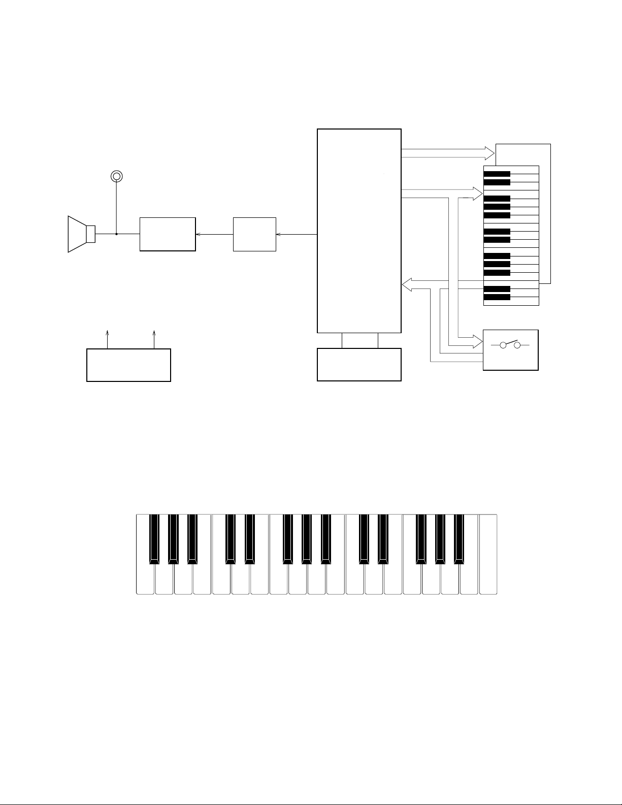
BLOCK DIAGRAM
KO0~KO11
KI0~KI7
Illuminated Keyboard
Switches
Oscillator
XL1
Amplifier
AN8053N
IC1
Speaker
CPU
MSM6521-11
LSI1
LEDs
LX0~LX3
LY0~LY7
Power Supply Circuit
T1, D4
VDD 5.6V
AVDD 5.6V
Filter
T2
Output Jack
Nomenclature of Keys
F#3 G#3 A#3 C#4 D#4 F#4 G#4 A#4 C#5 D#5 F#5 G#5 A#5
F3 G3 A3 B3 C4 D4 E4 F4 G4 A4 B4 C5 D5 E5 F5 G5 A5 B5 C6
— 2 —
Page 5
CIRCUIT DESCRIPTION
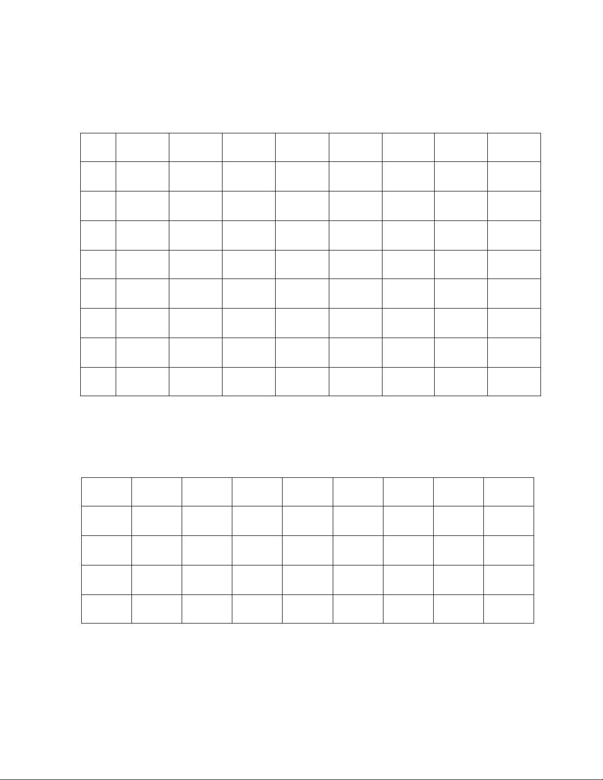
Key Matrix
KI0 KI1 KI2 KI3 KI4 KI5 KI6 KI7
KO0 F3 F#3 G3 G#3 A3 A#3 B3 C4
KO1 C#4 D4 D#4 E4 F4 F#4 G4 G#4
KO2 A4 A#4 B4 C5 C#5 D5 D#5 E5
KO3 F5 F#5 G5 G#5 A5 A#5 B5 C6
KO4
KO5 Tone 1
KO6 Tone 2 Tone 3 Tone 4 Tone 5
KO7
Melody
Guide
Any Key
Play
Volume
Down
Rhythm
Stop
Demo Play
Volume
Up
Tempo
Down
Rhythm
Select
Keyboard LED Matrix
LY0 LY1 LY2 LY3 LY4 LY5 LY6 LY7
LX0 C6 F5 E5 A4 G#4 C#4 C4 F3
LX1 B5 F#5 D#5 A#4 G4 D4 B3 F#3
Light
On/Off
Tempo
Up
LX2 A#5 G5 D5 B4 F#4 D#4 A#3 G3
LX3 A5 G#5 C#5 C5 F4 E4 A3 G#3
— 3 —
Page 6
CPU (LSI1: MSM6521-11)
Containing a sound data ROM and a DAC (Digital to Analog Converter), the CPU provides sound waveform in accordance with the pressed key and selected tone. The CPU also drives LEDs in the illuminated
keyboard directly. The following table shows the pin functions of LSI1.
Pin No. Terminal In/Out Function
1 ~ 7 LY1 ~ LY7 Out Keyboard LED drive signal output
8 LVDD1 In +5V source for the built-in LED driver
9 LGND2 In Ground (0V) source for the built-in LED driver
10 ~ 13 LX0 ~ LX3 Out Keyboard LED drive signal output
14 ~ 17 LX4 ~ LX7 Out Not used.
18 LVDD2 In +5V source for the built-in LED driver
19 GND2 In Ground (0V) source
20, 21 COSI, COSO In/Out 21.725 MHz clock pulse input/output
22 VDD In +5V source
23 GND1 In Ground (0V) source
24 ~ 26 TEST1 ~ TEST3 In Not used. Connected to ground.
27 RESET In Reset signal input. Power OFF: 0V, Power ON: +5V
28 AVDD In +5V source for the built-in DAC
29 OUT Out Sound waveform output
30 AGND In Ground (0V) source for the built-in DAC
31 ~ 38 KI0 ~ KI7 In Input terminal for keys and switches
39 ~ 46 KO0 ~ KO7 Out Key and switch scan signal input
47 ~ 58 Not used.
59 LGND1 In Ground (0V) source for the built-in LED driver
60 LY0 In Keyboard LED drive signal output
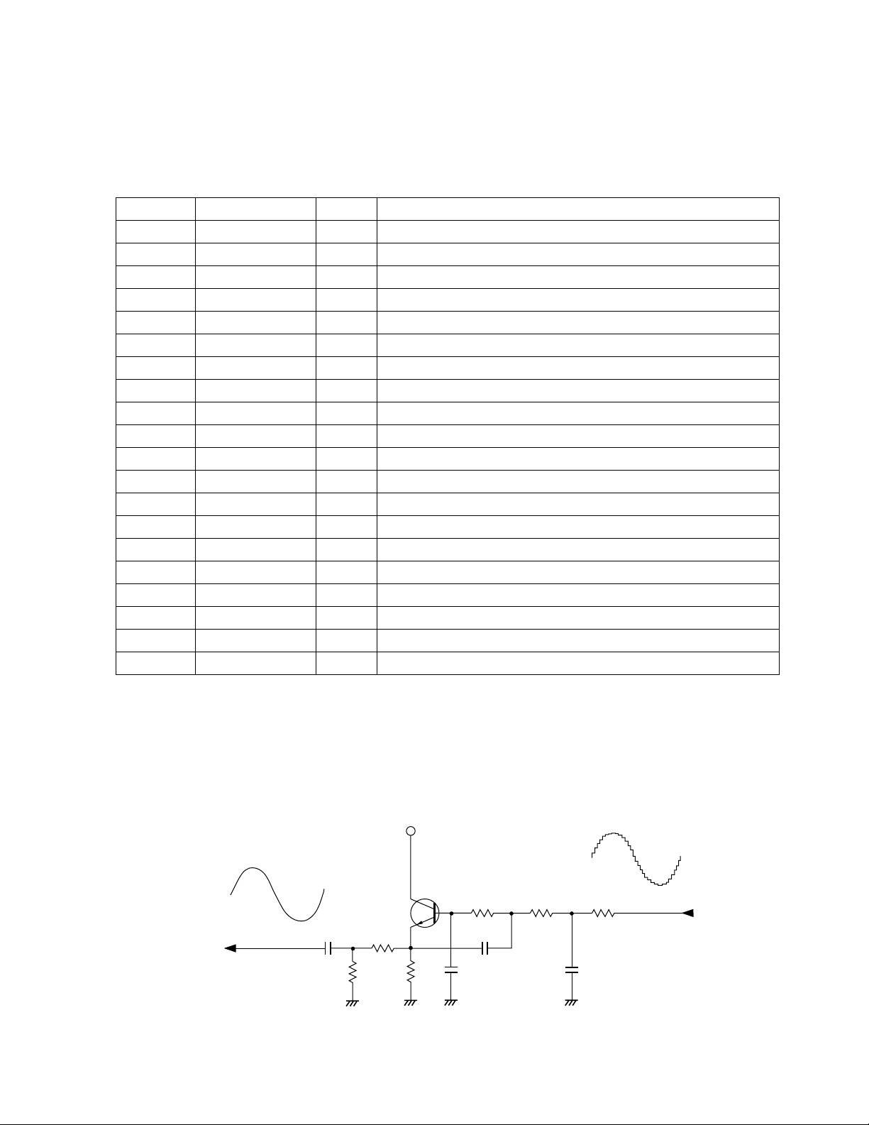
Filter Block
Since the sound signal from the CPU is a stepped waveform, the filter block is added to smooth the
waveform.
AVDD
T2
2SC1740SQ
C9
R1
AG
R30
R11
AG
— 4 —
C10
AG
R12
C11
R13
R14
C12
AG
Page 7

Power Supply Circuit
The power supply circuit regulates a constant output voltage +5.6V by T1 and D4.
T1
2SD1858Q,R
R37
D4
MTZJ6.8A
C3
R2
R5
R3 R4
R6
C4
DGGND
VDD +5.6V
D5
AVDD +5.6V
C5
AG
DC +7.5 V
Input
D2
Power Switch
ON
OFF
GND
TROUBLESHOOTING
Nature of Trouble Faulty Block Checkpoint
No power Power Supply Circuit Base of T1 should receive +6 V.
Emitter of T1 should provide +5.6 V.
Power switch Switch contact.
Power Jack (J1) Jack contact.
No sound at all Power Amp.
(IC1: AN8053N)
CPU (LSI1: MSM6521-11) Voltage at pin 27 should rise 0V to 5.6V
Oscillator (XL1) Pins 20 and 21 of the CPU should
Keyboard LEDs don't
light up
A certain key or switch
Keyboard LED
Keyboard LED Matrix Open circuir on LX or LY line.
Key and Switch Matrix Dust on the contact.
does not function
Certain keys or switches
Key and Switch Matrix Open circuit on KC or KI line.
do not function
Pin 16 should receive +7.5 V when the
power switch is turned on.
Voltage at pin 14 should drop at 0V
when the power switch is turned on.
Check output signal of pin 1.
when the power switch is turned on.
Pins 39 ~ 46 should provide pulses.
Pin 29 should have a sound signal when
a key is pressed.
receive an ocsillation signal.
— 5 —
Page 8

JCM605-KY1M
SCHEMATIC DIAGRAMS
— 6 —
Page 9

JCM605-LD2MJCM605-LD1M
— 7 —
Page 10

JCM605-MA1M/MA2M
MIHGFEDCBA J K L N OP
1
2
3
4
5
6.7
6.5
1
2
5
6
3
4
4
5.8
5
6
7
8
9
0.7
0.0
0.0
5.6
2.1
2.8
3
6
1
7
2
8
9
10
10
MIHGFEDCBA JKL NOP
— 8 —
Page 11

PCB VIEW AND MAJOR WAVEFORMS
3
4
3
4
Sound signal output
MSM6521-11 pin29
Power amp output
AN8053N pin 1
Key A3 ON
Key A3 OFF (5.6V)
5
6
5
6
LED drive signal LY7
JC connector pin1
LED drive signal LX3
JC connector pin11
2 31 4
1
2
1
Key scan signal KO0
MSM6521-11 pin39
56
2
Key scan signal KO7
MSM6521-11 pin46
— 9 —
Page 12

EXPLODED VIEW
10
12
11
1
4
3
8
2
16
17
7
9
x 7
x 7
x 3
x 6
x 10
x 6
x 14
6
15
13
5
14
— 10 —
Page 13

IC LEAD IDENTIFICATION
LSI1: MSM6521-11
47
48
49
50
51
52
53
54
55
56
57
58
59
60
464544434241403938373635343332
KO7
KO6
KO8
KO9
KO10
KO11
D4
D3
D2
D1
OP
Ø2
Ø1
CE
GND1
LY0
KO5
LY1
LY2
123456789
KO4
LY3
KO3
LY4
KO2
LY5
KO1
LY6
KO0
LY7
KI7
LVDD1
LGND2
IC1: AN8053N
16
15
14
13
31
KI6
KI5
KI4
KI3
KI2
KI1
LX0
LX1
LX2
LX3
LX4
LX5
10111213141516
12
11
10
9
KI0
AGND
OUT
AVDD
RESET
TEST3
TEST2
TEST1
GND1
VDD
COSO
COSI
GND2
LVDD2
LX7
LX6
30
29
28
27
26
25
24
23
22
21
20
29
28
17
VCC
SPONCSPG
1
T1: 2SD1858Q, R
NC
2
CONT
VREG
PC-1
3
4
NC
PC-2
5
NC
SPI
6
NC
SPM
7
PR GND
VREF
8
T2, T3: 2SC1740SQ
— 11 —
Page 14

PARTS LIST
ML-2
Notes: 1. Prices and specifications are subject to change with-
out prior notice.
2. As for spare parts order and supply, refer to the
"GUIDEBOOK for Spare parts Supply", published
seperately.
3. The numbers in item column correspond to the same
numbers in drawing.
Page 15

FOB Japan
N Item Code No. Parts Name Specification Q M N.R.Yen R *
Unit Price
Main PCB Ass'y
N LSI1 2011 7497 LSI MSM6521-11 1 1 780 A H
IC1 2114 3269 IC AN8053N 1 1 120 A B
T1 2253 0448 Transistor 2SD1858Q,R-TV6-T 1 1 24 A A
T2/3 2220 1387 Transistor 2SC1740SQ-TP-T 2 10 13 B A
D1 2390 0371 Diode DSK10B-BT-T 1 10 11 B A
D2 2390 1323 Diode RB100A-T32-T 1 10 29 B A
D4 2360 1519 Zener diode MTZJ6.8A-T77-T 1 10 8 A A
D5/6 2390 1344 Diode 1SS133T-77-T 2 10 3 C A
XL1 2590 0742 Ceramic oscillator EFO-GC2175C3 1 1 64 B B
R1 2606 1491 Carbon film resistor R-20-6.8K-J-T23-T 1 20 2 C A
R2~4 2606 1722 Carbon film resistor R-20-2.2-J-T23-T 3 20 2 C A
R5/6 2606 1477 Carbon film resistor R-20-33-J-T23-T 2 20 2 C A
R9/10 2606 1232 Carbon film resistor R-20-82-J-T23-T 2 20 2 C A
R11 2606 1141 Carbon film resistor R-20-1K-J-T23-T 1 20 2 C A
R12~14, 21~28 2606 1253 Carbon film resistor R-20-4.7K-J-T23-T 12 20 2 C A
R15 2606 1162 Carbon film resistor R-20-10-J-T23-T 1 20 2 C A
R16~19 2606 1708 Carbon film resistor R-20-47-J-T23-T 4 20 2 C A
R20 2606 1365 Carbon film resistor R-20-3.9K-J-T23-T 1 20 2 C A
R29~36 2606 1288 Carbon film resistor R-20-2.2K-J-T23-T 8 20 2 C A
R37 2606 1309 Carbon film resistor R-20-470-J-T23-T 1 20 2 C A
C2 2807 0985 Electrolytic capacitor 16RE2-220-T2-T 1 10 30 C A
C3 2805 3142 Electrolytic capacitor 16RE2-10-T2-T 1 10 14 C A
C4 2807 1091 Electrolytic capacitor 6.3RE2-100-T2-T 1 10 18 C A
C5 2805 3061 Electrolytic capacitor 6.3RE2-220-T2-T 1 10 26 C A
C6 2807 0926 Electrolytic capacitor 10RE2-470-T2-T 1 10 36 C A
C7/8 2805 3134 Electrolytic capacitor 10RE2-22-T2-T 2 10 14 C A
C9 2813 1932 Semiconductive capacitor RT-B50TKYR223K-T 1 20 5 C A
N C10 2813 2947 Semiconductive capacitor RT-C40TKYR122K-T 1 20 4 C A
C11 2813 3094 Semiconductive capacitor RT-C50TKYR153K-T 1 20 4 C A
C12 2813 1729 Semiconductive capacitor RT-C40TKYR472K-T 1 20 4 C A
C13 2807 1040 Electrolytic capacitor 6.3RE2-470-T2-T 1 10 27 C A
C15,17 2813 3283 Ceramic capacitor UP050F104Z-A-B 3 20 8 C A
C18 2807 1023 Electrolytic capacitor 50RE2-1-T2-T 1 10 15 C A
MC1 2845 0168 Module capacitor CNB8X101K 1 1 58 C B
FB1~5 3035 0266 Ferrite beads BL02RN2-R62T4-T 5 10 13 C A
J1 3501 3731 DC jack HEC2305-01-250 1 1 30 B A
J2 3501 4382 Jack HSJ2000-01-010 1 1 56 C B
N JA 3719 4319 Ribbon cable M605A DF5H12085-5000M 1 1 30 C A
N JB 3719 4326 Ribbon cable M605B DF5H12095-5000M 1 1 27 C A
N JC 3719 4333 Ribbon cable M605C DF5H12115-5000M 1 1 31 C A
L1 3841 1057 Common mode coil CM05RB01 1 1 63 C B
N 4317 5032 Blank PCB JCM605-MA1M M211783B-1 1 1 160 C B
N 4317 5042 Blank PCB JCM605-MA2M M211783B-2 1 1 16 C A
N 1 6921 8160 PCB ass'y M605-MA1,2M M111821*1 1 1 1740 B P
6922 1750 Battery spring (+) 522A M412225-1 1 20 7 B A
6922 1760 Battery spring (-) 522B M412226-1 1 20 10 B A
LED PCB ass'y
N 2 6922 6890 PCB ass'y M605-LD1M M211795*1 1 1 880 C J
N 4317 5010 Blank PCB JCM605-LD1M M211781-1 1 1 54 C B
N 2370 1043 LED KR3301X-J171K 19 10 38 B A
N 3 6922 6900 PCB ass'y M605-LD2M M211796*1 1 1 650 C G
N 4317 5020 Blank PCB JCM605-LD2M M211782-1 1 1 45 C A
N 2370 1050 LED KR3302X-J173K 13 10 38 B A
Notes: N – New parts
M – Minimum order/supply quantity
R – Rank
— 13 —
Page 16

FOB Japan
N Item Code No. Parts Name Specification Q M N.R.Yen R *
Unit Price
Mechanical Parts
N 4 4317 5081 Blank PCB JCM605-KY1 M211780A-1 1 1 88 C B
5 3831 0378 Speaker EAS-8P149BD 1 1 160 B B
6 6922 6930 Slide knob 521 M311280-4 1 5 19 B A
N 6 6922 7670 Slide knob 521 M311280-5 1 5 19 B A
N 7 6922 6821 L-LIMIT-LNM32 M412337A-1 1 1 36 C A
N 8 6922 6810 U-LIMIT-LNM32 M412336-1 1 1 28 C A
N 9 6922 6791 Upper case (Black) M211786A*2 1 1 440 C D
N 9 6922 6741 Upper case (Light gray) M211786A*1 1 1 440 C D
N 10 6922 6780 KY-PANEL-605 M211772-1 1 1 150 C B
N 11 6906 7203 Black key set LNM32 M110553C-3 1 1 70 A B
N 12 6922 6760 White key set LNM32 M117817-1 1 1 160 A B
13 6909 5890 Slide contact12D CSB-12D 1 5 35 B A
N 14 6922 6770 Rubber button 605 M211778-1 1 1 170 B B
15 6917 1080 Key contact rubber NM32 M310878-1 1 1 87 B B
N 16 6922 6720 Lower case sub ass'y M211789*1 1 1 280 C C
N 17 6906 7193 Battery cover sub ass'y M311200C*15 1 10 32 B A
N 6922 6910 Rating label M312199-2 1 10 8 C A
0009 5573 Screw 2.6x10 14 50 2 C A
0009 5574 Screw, washer head 2.6x6 6 50 2 C A
0009 2682 Screw 2.6x8 34 50 2 C A
Notes: N – New parts
M – Minimum order/supply quantity
R – Rank
— 14 —
Page 17

MA0700941A
 Loading...