

Page 1
TECHNICAL MANUAL
(without price)
DOT PRINTER
MD-910
JAN. 1997
Page 2

Features
The MD-910 series is a dot matrix compact printer that uses two serial print heads.
This printer has been developed as an output terminal for various applications such as POS terminals,
measuring/analyzing equipment, medical equipment and communication data equipment, and has
been designed to be as compact as possible.
• Compact and lightweight
• High-speed printing of up to 2.5 lines/sec. (for MD-910) or 1.8 lines/sec. (for MD-911)
• Clear printout with high resolution of 8 dots/mm
• Paper width of print head
• Longer life of print head
• Simple mechanism for high-reliability
Page 3

Contents
1 Printer usage and Care..................................................................................................................... 1
2 Specifications/Operating principles ................................................................................................... 2
2-1 Specifications............................................................................................................................ 2
2-2 Outline of mechanism ............................................................................................................... 3
2-3 Mechanism and operation principles ........................................................................................ 3
2-3-1 Power transmission mechanism ................................................................................... 3
2-3-2 Sensor mechanisms ..................................................................................................... 4
2-3-3 Print head mechanism.................................................................................................. 5
2-3-4 Paper feed mechanism................................................................................................. 8
2-3-5 Ribbon cartridge drive mechanism ............................................................................. 11
2-4 External connection terminals................................................................................................. 11
2-4-1 Terminal arrangement ................................................................................................ 11
2-4-2 Terminal mechanism .................................................................................................. 12
2-4-3 Terminal circuit diagram ............................................................................................. 12
3 Disassembly/Reassembly............................................................................................................... 13
3-1 Tools .................................................................................................................................... 13
3-2 Disassembly procedure .......................................................................................................... 13
3-3 Assembly procedure ............................................................................................................... 14
3-3-1 Setting paper feed solenoid assembly........................................................................ 14
3-3-2 Setting the head assembly ......................................................................................... 15
3-3-3 Setting the paper feed assembly ................................................................................ 16
3-3-4 Setting the main body assembly................................................................................. 18
4 Parts list .................................................................................................................................... 26
5 Exploded view................................................................................................................................. 28
Page 4
1 Printer usage and Care
(1) Use recommended register paper. Otherwise, printing quality and the life of the print head will not be
guaranteed. The width of paper must meet the specifications.
(2) Never allow a mechanical impact (including the entry of foreign matter) to the print head surface.
(3) Any dust on the print head surface must be wiped off by an applicator soaked in ethanol or the
equivalent.
(4) The dedicated ribbon cartridge should be taken off when the printer is carried or not used for a long
period.
(5) Do not feed current to the print head if it is wet or moist. If current is fed, the print head may be
damaged. If the print head is wet or moist, dry it fully and then start printing.
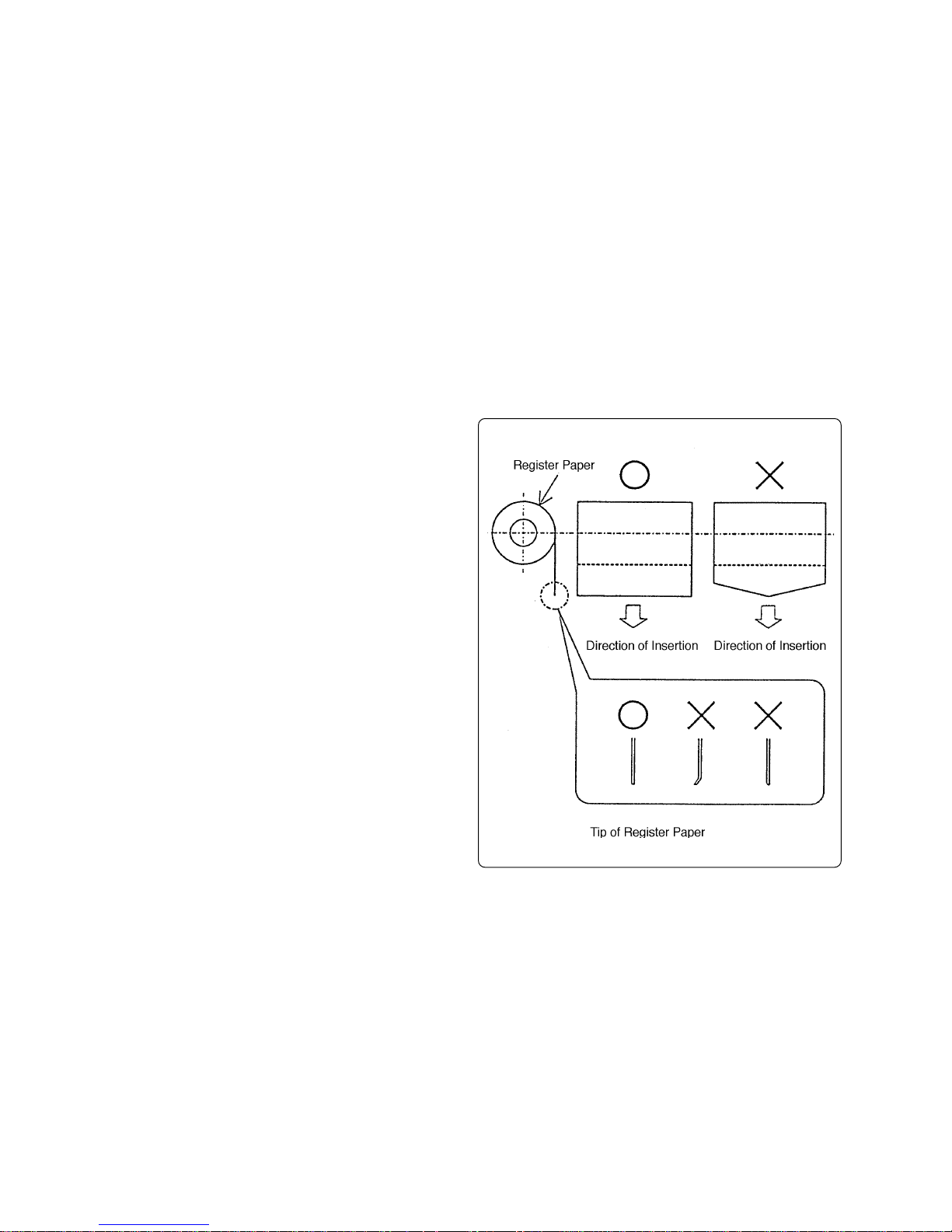
(6) Inserting register paper
• Cut the top end of the register paper
straight (it should never be fluffed or bent)
and insert it.
• When the top end of the register paper
comes out of the print head, check that it
is set straight and then pull it.
(7) Removing register paper
• Before removing the register paper, be sure
to stop feeding current to the print head.
• Pull out paper straight in the direction of
paper exit.
— 1 —
Page 5

2 Specifications/Operating principles
2-1 Specifications
Item Specifications
Printing method Dot matrix system
Printing direction Unidirectional printing
Printing speed 2.5 lines/sec. ± 20 %; DC 5.0 V, 25 °C in
continuous printing
Printing format Number of dots 144 dots/line
Character configuration (5 + 1) × 8
Number of columns 24
Paper feeding Paper feeding pitch 3.52 mm (10 dots/line)
Rapid feed rate 5 lines/sec. ± 20 %; DC 5.0 V, 25 °C in
continuous printing
Inking Dedicated cartridge (black or purple)
Detection Dot pulse Photointerrupter
Reset pulse Leaf switch detector
Paper feeding solenoid Drive voltage DC 5.0 V
Resistance 7 h ± 3 (temperature: 25 °C)
Printing solenoid Drive voltage DC 5.0 V
Resistance 1.7 h ± 0.3 (temperature: 25 °C)
Motor Type DC brush motor
Drive voltage DC 5.0 V
Max. current Approx. 1 A
Average current 0.3 A or less; DC 5.0 V, 25 °C in continuous
printing
Paper Type Plane or recommended paper
Paper width 57.5 mm
Cut sheet 45 to 55 kg
(thickness: 0.06 to 0.085 mm)
Copies Original paper (34 kg) + single copy (34 kg)
(Total thickness: 0.13 mm or less) Non-carbon
paper
Life of print head 1,500,000 lines
Exterior dimensions 90 (w) × 45.5 (d) × 15.8 (h) ± 0.5 mm
(excluding paper feeding nob and feet)
Weight 105 g ± 10 %
— 2 —
Page 6
2-2 Outline of mechanism
This printer mechanism is divided roughly into the following seven blocks:
• Power transmission
• Sensor
• Print head
• Paper feed
• Ribbon cartridge drive
• Frame
• Motor
For example external control circuits attached to this printer, please see the appropriate operating
manuals.
2-3 Mechanism and operation principles
The mechanism and operating principles are described for five blocks out of seven (i.e., excluding
the frame and motor).
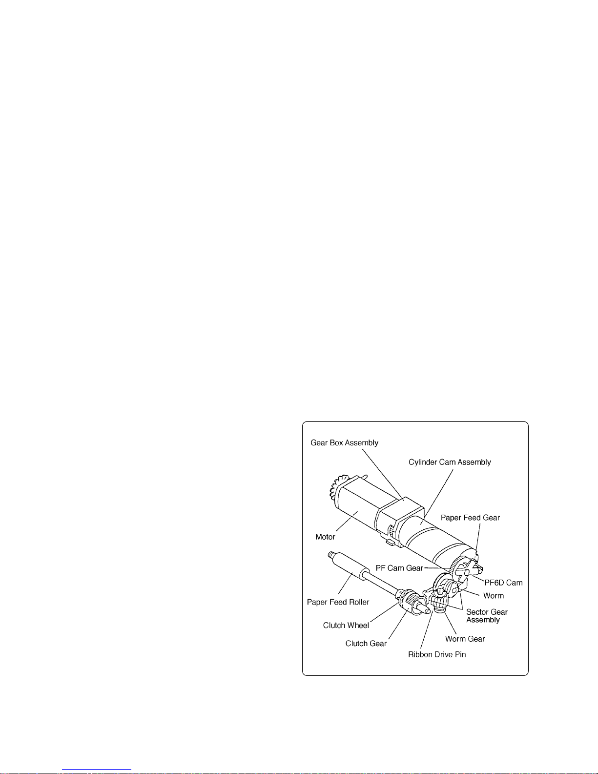
2-3-1 Power transmission mechanism
This mechanism transmits a motor driving force to the head assembly, paper feed roller and ribbon
cartridge.
The head assembly is driven by the cylinder cam assembly connected to the gear box assembly
which encloses the motor.
The driving force transmitted to the cylinder cam assembly is sent to the PF cam
gear and PF6D cam through the paper
feed gear. Either the driving force transmitted to the PF cam gear or the driving
force transmitted the PF6D cam can be
selected, depending on the operation status, and is sent to the clutch gear through
the sector gear assembly.
The driving force of the clutch gear is
transmitted to the clutch wheel connected
to the paper feed roller, driving the paper
feed roller.
The driving force of the PF cam gear is
transmitted to the worm, worm gear and
ribbon drive pin respectively, so that the
ribbon cartridge is driven by the ribbon
drive pin.
— 3 —
Page 7
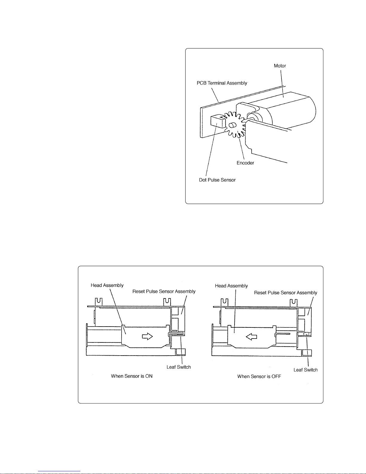
2-3-2 Sensor mechanisms
This mechanism has two sensors for detection, a dot pulse sensor and a reset
pulse sensor.
(1) Dot pulse sensor
The dot pulse sensor consists of an
encoder (slit disk) directly connected
to the motor and a photointerrupter
reading the rotation. The rotation read
(number of slits counted) is treated as
the DP signal that is the core of the
printing control.
(2) Reset pulse sensor
The reset pulse sensor uses a leaf switch which turns ON/OFF according to the head assembly position.
This sensor detection signal represents the RP signal that specifies the print head home position and printing start base position.
— 4 —
Page 8
2-3-3 Print head mechanism
This printer has two print heads arranged at intervals on the left and right, so that the left half and
the right half of the register paper can be printed simultaneously as it is moved from left to right.
One movement causes the upper part of one line to be printed and the next movement causes the
lower part of the line to be printed. Therefore, two print head movements complete printing of one
line. The print heads, however, print the register paper only when they move from left to right.
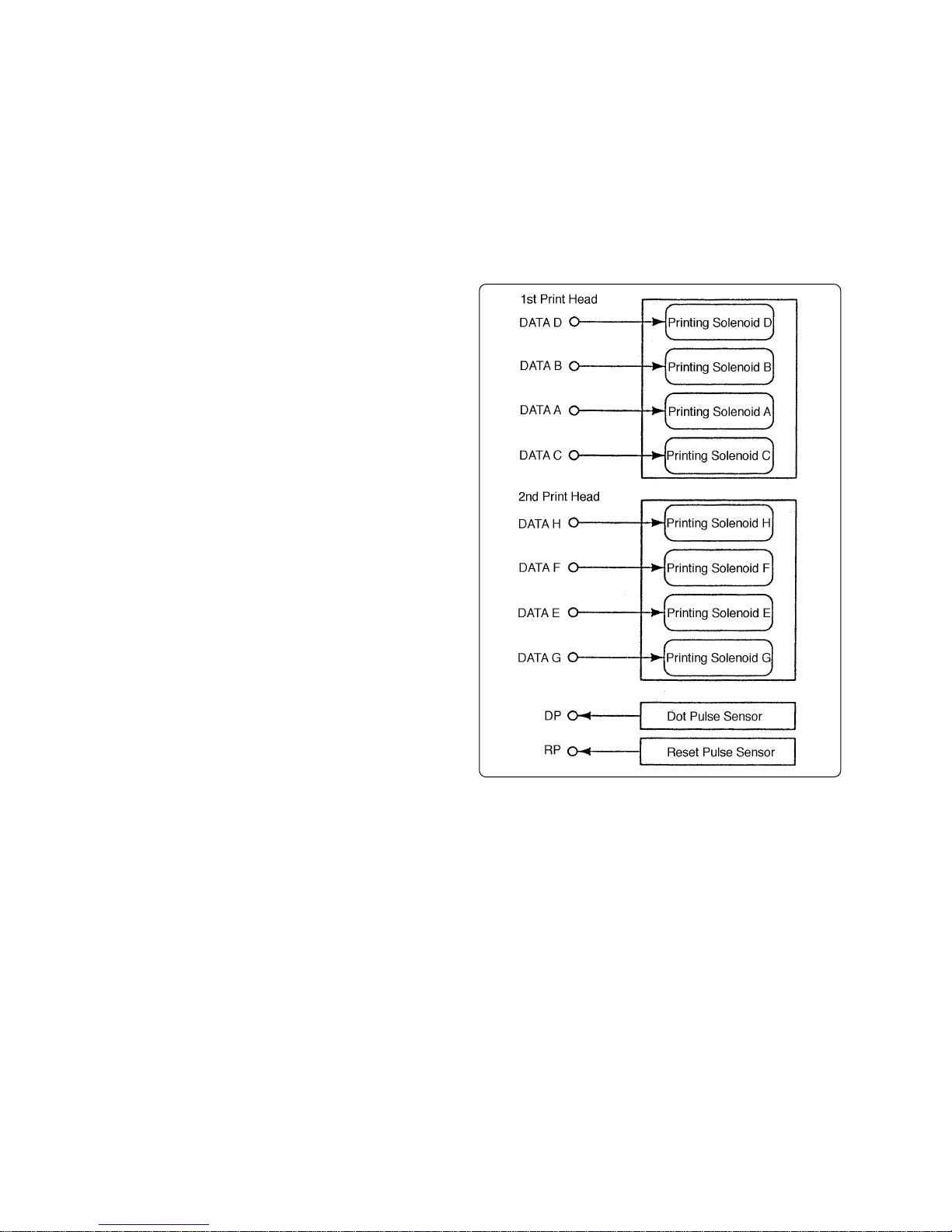
(1) Printing control
Each print head has four printing solenoids and each solenoid is turned
ON/OFF according to the printing data
and the corresponding printing pins
are activated to form character dots.
This printer, however, does not have
a serial/parallel conversion circuit.
Therefore, ON (L level)/OFF (H level)
signals are directly provided to the
eight data lines for each printing solenoid.
Printing timing is controlled by the DP
signal which is detected by the dot
pulse sensor and is treated as a clock
pulse and the RP signal which is detected by the reset pulse sensor and
is treated as a starting point.
— 5 —
Page 9
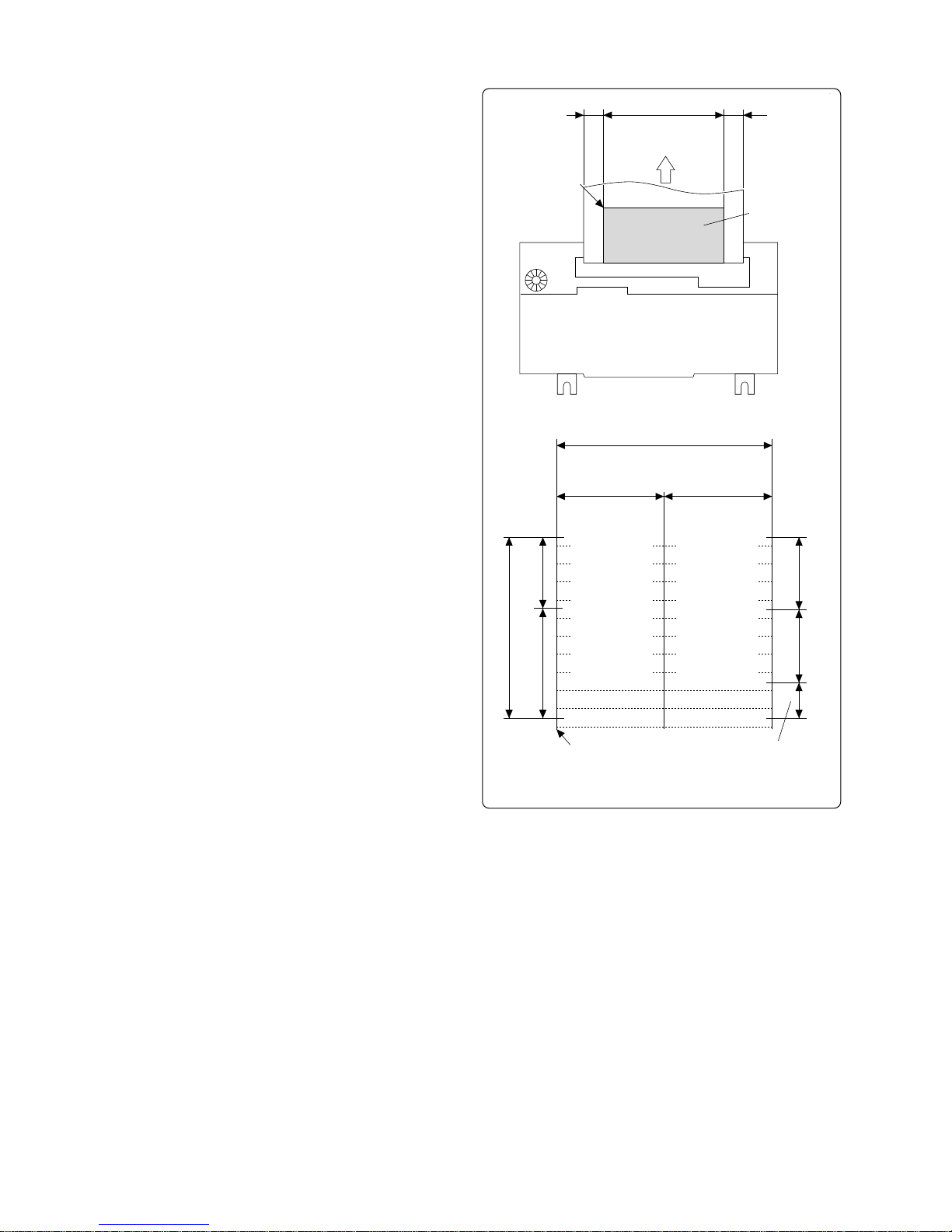
(2) Printing data and printing position
The number of printing columns and
one character dot matrix vary , depending on whether the printer is the MD910 or MD-911.
For the MD-910, the number of printing columns is 24, and each 12 columns of printing on the left and right is
performed by each print head. 4 dots/
line is produced by one print head
movement.
6 (5 + 1) horizontal dots make up one
character and the total number of horizontal dots in the printable area is 144
(12 columns × 2 × 6 dots).
For the MD-911, the number of printing columns is 40, and each 20 columns of printing on the left and right is
performed by each print head. 4 dots/
line is produced by one print head
movement. 4.5 (4 + 0.5) horizontal dots
make up one character and the total
number of horizontal dots in the printable area is 180 (20 columns × 2 × 4.5
dots).
5 mm 47.5 mm 5 mm
Home Position
12 (20) Columns
One Line
2/2 Line 1/2 Line
Direction of
Paper Feed
Printing Position
Printable Area
144 (180) Dots
1st Print Head 2nd Print Head
12 (20) Columns
72 (90) Dots
Printing Solenoid A
Printing Solenoid B
Printing Solenoid C
Printing Solenoid D
Printing Solenoid A
Printing Solenoid B
Printing Solenoid C
Printing Solenoid D
72 (90) Dots
Printing Solenoid E
Printing Solenoid F
Printing Solenoid G
Printing Solenoid H
Printing Solenoid E
Printing Solenoid F
Printing Solenoid G
Printing Solenoid H
Printable Area
4 Dots/Line 4 Dots/Line
— 6 —
2 Dots/Line: LFHome Position
Printable Area in Detail
(Values parenthesized are for MD-911)
Page 10
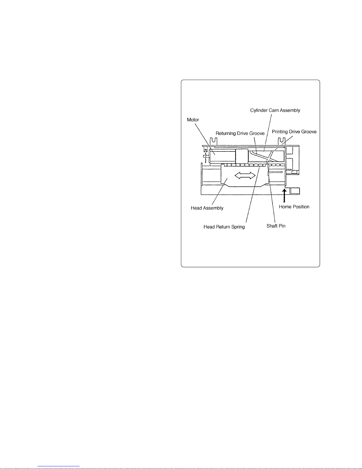
(3) Head drive mechanism
The head assembly is connected to the cylinder cam assembly via a shaft pin. The shaft pin is
inserted in a scribed groove on the outside of the cylinder cam assembly and moves along the
groove when the cylinder cam assembly is turned to drive the head assembly.
When the head assembly travels beyond the home position, the shaft pin
goes through a sharp curve in the
scribed groove, so it moves slowly.
At this time, printing is performed.
When the head assembly travels beyond the printable area, the direction
of movement is changed to the home
position because the direction of
groove is reversed and the head return spring tension is activated.
At this time, the head assembly travels at high-speed because the groove
is turned to the slow curve.
Register paper feeding is performed
when the head assembly returns.
When the head assembly travels to
the home position, it returns to the
original groove position, and the operation is repeated.
— 7 —
Page 11

2-3-4 Paper feed mechanism
Since this printer completes one line of printing by dividing it into upper and lower halves, two types
of paper feeding are provided; one is paper feeding without LF (line feed) because the lower half is
printed after the upper half.
The other is paper feeding with LF because upper half of the next line is printed after completing
one line.
(1) Paper path
The register paper is loaded from the
back of the printer and moved to the
paper feed roller and the pressure
roller along the paper pressure guide.
The register paper moved is pressed
against the paper feed roller by the
pressure roller and fed upward when
the paper feed roller turns.
The register paper then passes
through the platen and the print head
and comes out to the back again.
When the register paper passes
through the platen and the print head,
it is printed by the ink ribbon of the
ribbon cartridge on the print head.
— 8 —
Page 12

(2) Paper feeding without LF (line feed) mechanism
The PF cam gear that drives paper feeding turns one time per head assembly shuttle.
The cam inside the PF cam gear presses down the protrusion (part A) of the sector gear
assembly when the head assembly returns. The sector gear assembly has teeth on the opposite side of the protrusion which engage with the clutch gear that is concentric to the paper feed
roller .
The paper feed roller has a clutch
wheel next to the clutch gear to transmit the driving force.
Normally this clutch wheel is not in contact.
The sector gear assembly has a fulcrum at the middle, so if the protrusion
is pressed down, the teeth are raised
to turn the clutch gear. The clutch gear
then is pushed out by the PF clutch
spring and engages with the clutch
wheel to rotate the paper feed roller.
This rotation, i.e., the paper feeding,
depends on the amount of ascent of
the teeth of the sector gear assembly.
4 dots/line is ensured without LF.
When the cam inside the PF cam gear
goes past due to rotation, the protrusion of the sector gear assembly is
raised again by the sector gear spring
so that the clutch gear separates from
the clutch wheel and stops the paper
feed roller.
— 9 —
Page 13

(3) Paper feeding with LF (line feed) mechanism
In paper feeding with LF mechanism, only the protrusion pressing down mechanism is different
from that of paper feeding without LF mechanism.
Two cotter pins are set on the outside of the PF cam gear and turn together with the PF cam
gear. The cotter pins are always exerting a force to uncoil but are restrained by the return ring.
One part of the return ring is thin, so that when the cotter pin passes through this thin part while
rotating, it springs out of the return ring.
When performing paper feeding without LF, no cotter pin spring is required, so the armature
assembly is inserted in the thin part of the return ring instead. The armature assembly is linked
with the paper feed solenoid.
When performing paper feeding with
LF, the paper feed solenoid turns ON
and the armature assembly is detached from the return ring.
The PF6D cam is set on the outside
of the return ring and the driving force
of the PF cam gear is transmitted by
the cotter pin spring.
As the PF6D cam turns, the outer protrusion (part B) of the sector gear assembly is lowered and the paper feed
roller rotates in the same manner as
during paper feeding without LF
mechanism. At this time, the PF6D
cam is larger than the cam inside the
PF cam gear, so the rotation of the
paper feed roller is 6 dots/line, i.e., 2
more dots per line than with paper
feeding without the LF.
— 10 —
Page 14

2-3-5 Ribbon cartridge drive mechanism
The PF cam gear that drives paper feeding is also used to turn the ribbon cartridge.
The driving force of the PF cam gear is
transmitted to the worm where the direction of operation is changed 90 °.
The driving force converted is transmitted
from the worm to the worm gear and the
ribbon cartridge is turned by the ribbon
drive pin. Therefore, the ribbon cartridge
is always moving while printing is being
performed.
2-4 External connection terminals
External connection terminals are located within the PCB terminal assembly and their connections
are implemented by directly soldering the print pattern surface.
2-4-1 Terminal arrangement
— 11 —
Page 15

2-4-2 Terminal mechanism
Terminal No. Terminal name Remarks
1 Motor (–) Motor is ON with GND
2 Phototransistor emitter Dot pulse sensor
3 Phototransistor collector
4 LED cathode
5 LED anode
6 Printing solenoid D (–) 1st print head
7 Printing solenoid B (–) Each solenoid is ON with GND
8 Printing solenoid A (–)
9 Printing solenoid C (–)
10 Common (+) Power side of print head, motor and paper
11 Printing solenoid H (–) 2nd print head
12 Printing solenoid F (– ) Each solenoid is ON with GND
feeding solenoid
13 Printing solenoid E (–)
14 Printing solenoid G (–)
15 Paper feeding solenoid (–) Solenoid is ON with GND
16 Reset pulse sensor output Power side
17 Reset pulse sensor output GND side
2-4-3 Terminal circuit diagram
Paper Feeding Solenoid
Motor Dot Pulse Sensor 1st Printing Head 2nd Printing Head Reset Pulse Sensor
Printing
+
Solenoid
D
Printing
Solenoid
A
Printing
Solenoid
H
Printing
Solenoid
E
M
–
Printing
Solenoid
B
Printing
Solenoid
C
Printing
Solenoid
F
Printing
Solenoid
G
2345 6789 1110 161512 13 14
1
17
Note: 1. For motor polarity, terminal No. 1 should be minus.
2. For reset pulse sensor, terminal No. 17 should be GND.
— 12 —
Page 16

3 Disassembly/Reassembly
Prior to maintenance work, be sure to observe the following caution:
CAUTION
(1) When the printer is operating satisfactorily , do not unnecessarily disassemble, reas-
semble or adjust the printer. In particular, do not loosen any screws on the compo-
nents.
(2) Check that the printer is in good condition before turning on the power.
(3) Never try to print without register paper in the printer.
(4) Check that the register paper is set properly.
(5) In maintenance work, never leave any parts or screws in the printer.
(6) In disassembly and reassembly, check that any wires and cords are not damaged
and are laid out properly. Handle these wires and cords carefully.
3-1 Tools
The list of necessary tools is as follows:
1. Philips head screwdriver
2. Tweezers
3. Small radio pliers
4. Oil brush
5. Small pincers
3-2 Disassembly procedure
To perform disassembly, reverse the assembly procedure (item 3-3).
Disassemble each part gradually from the frame.
— 13 —
Page 17

3-3 Assembly procedure
The assembly procedure is described by major assembly blocks.
Part names in text are the same as those in Parts List.
3-3-1 Setting paper feed solenoid assembly
(1) Place the core in core base as-
sembly. At this time, align the pro-
trusion of the core with the hole
of the core base assembly.
(2) Insert the bobbin assembly where
the core has already been fitted
in the core base assembly. At this
time, the lead wires face outside
and there should be no gap be-
tween the bobbin assembly and
the core base assembly.
— 14 —
Page 18

(3) First apply Froil G-311S to the arma-
ture pivot of the bobbin assembly, then
install the armature spring and the ar-
mature assembly. At this time, check
the direction of armature spring.
(4) Secure the armature assembly with
the E-ring and attach the armature
spring to the hole of the armature as-
sembly.
Note:When installing the E-ring and
armature spring, use small radio
pliers or tweezers.
3-3-2 Setting the head assembly
(1) Two tips of FPC are extended from the
head assembly. Bend the two tips at
right angles from the notch line.
— 15 —
Page 19

(2) Place the ribbon mask in the head as-
sembly. At this time, align the holes of
the ribbon mask with the protrusions
of the head assembly.
Note:The ribbon mask is very thin, so
take care not to bend it when installing it.
(3) Install the head return spring in the
head assembly.
3-3-3 Setting the paper feed assembly
(1) Apply Froil G-311S to the two parts of
the paper feed roller shaft where pa-
per feed bracket touches.
(2) Apply Epnoc grease AP to the brake
groove of the paper feed roller.
Note:The paper feed roller must be
free from sticky oil.
(3) Place the paper feed roller in the pa-
per feed bracket. At this time, the
longer shaft should be inserted first.
— 16 —
Page 20

(4) Install the PF bracket bushing in the
bushing groove of the paper feed
bracket and secure the paper feed
roller.
(5) Install the brake spring in the brake
groove of the paper feed roller.
(6) Attach the platen to the paper feed
bracket with two platen spacers and
two screws (M2 × 2.5).
(7) Insert the clutch wheel in the paper
feed roller shaft coming out of the pa-
per feed bracket.
Note:When inserting, push the clutch
wheel until the claws of the
clutch wheel are engaged with
the shaft groove of the paper
feed roller.
(8) Insert the clutch gear in the paper feed
roller shaft.
(9) Apply Froil G-311S to the gear section
of the clutch gear.
— 17 —
Page 21

3-3-4 Setting the main body assembly
(1) Apply Froil G-311S to the gear of the
gear box assembly, the shaft of the
cylinder cam assembly and the teeth,
the opposite of the shaft.
(2) Combine the cylinder cam assembly
with the gear box assembly and install
the cam shaft bushing in the shaft of
the cylinder cam assembly. Then put
block assembled in frame assembly.
Note:
1) When assembling, align the protrusion of the gear box assembly with
the hole on the bend of the frame
assembly.
2) After assembling, align the protrusion, a whirl-stop of the cam shaft
bushing with the notched hole on
the right of the frame assembly.
(3) Bend the notched section on the left
of the frame assembly to secure the
motor of the gear box assembly.
Note:
1) After securing this, check that the
cylinder cam assembly turns
smoothly. If not, reinstall it.
2) Handle the notched section on the
left of the frame assembly carefully
because it may be damaged if it is
bent and turned often.
(4) Insert the paper feed gear in the shaft
of the cylinder cam assembly.
Note:When inserting the gear, push
the claws of the paper feed gear
until they fully engage with the
shaft grooves.
— 18 —
Page 22

(5) Apply Froil G-311S to the pivot of the
PF cam and the cam of the PF cam
gear.
(6) The cam faces inside. Insert the PF
cam gear in the pivot of the PF cam.
Note:
1) When inserting the gear, turn the
cylinder cam assembly beforehand
so that the claws of the paper feed
gear are horizontal. At this time, the
squared notch of the cylinder cam
assembly should face the back.
2) Four-sectored protruding parts of
the PF cam gear should face the
outside.
Engage the center of the protruding part that is horizontal when the
inside cam faces down with the paper feed gear.
(7) Apply Froil G-311S to the two cotter
pin springs and then insert them in
cotter pins.
(8) Put the two cotter pins in the PF cam
gear.
— 19 —
Page 23

(9) Apply Froil G-311S to the upper sur-
face of the PF cam gear.
(10)Install the return ring and the PF6D
cam in the PF cam gear and secure it
with the E-ring.
(11) Apply Froil G-311S to the outside and
surfaces of the PF6D cam.
(12)Insert the pressure roller in the pres-
sure roller shaft and set it in the frame
assembly .
Note:The pressure roller must be set
in the notched hole of the frame
assembly .
— 20 —
Page 24

(13)Mount the paper pressure guide on the
back of the frame assembly.
(14)Set the PF clutch spring and the clutch
spacer in the clutch gear of the paper
feed and then put it in the frame assembly from over the paper pressure
guide.
Note:
1) The clutch spacer must be set from
the right of the frame assembly to
the inside.
Therefore, set it while the PF clutch
spring is shortened.
2) When assembling, align the protrusions on the bottom of the paper
feed bracket with the holes of the
frame assembly.
(15)Secure both the paper feed and the
paper pressure guide to the frame assembly with two screws (M2 × 2.5).
(16)Apply Froil G-311S to the pivot of the
ribbon drive and the teeth of the sector gear assembly.
(17)Insert the sector gear assembly in the
pivot of the ribbon drive.
Note: When inserting the assembly,
engage the bottom teeth of the
sector gear assembly with the
final gear of the clutch gear.
— 21 —
Page 25

(18)Apply Froil G-311S to the bushing of
the sector gear assembly and then insert the worm and secure it with the
E-ring.
(19)Set the sector gear spring between the
sector gear assembly and the frame
assembly.
(20)Apply Froil G-311S to the fitting hole
of the ribbon drive and then insert the
ribbon drive pin from under the bottom of the frame assembly.
(21)Insert the worm gear in the ribbon drive
pin.
— 22 —
Page 26

(22)Apply Froil G-311S to the upper sur-
face of the worm gear and then install
the ribbon drive latch and the latch
spacer and secure them with the push
nut.
Note:When installing these, check the
direction of ribbon drive latch.
(23)Secure the solenoid assembly to the
right of the frame assembly with a
single screw.
(24)Install the reset pulse sensor assem-
bly to the right of the frame assembly
and secure it by bending the notched
section of the right of the frame assembly .
Note:Handle the notched section of
the right of the frame assembly
carefully because it may be damaged if it is bent or turned often.
(25)Secure the PCB terminal assembly to
the front of the frame assembly with
two screws (M2 × 2.5).
— 23 —
Page 27

(26)Apply Froil G-311S to the tip of the re-
set arm and the two shaft bushings of
the head assembly.
(27)Set the shaft pin in the head assem-
bly.
(28)Hang one end of the head return
spring, which is set in the head assembly, on the notched section of the right
of the head assembly.
(29)Insert the tip of the shaft pin, which is
set in the head assembly, in the groove
of the cylinder cam assembly.
Note:Before insertion, the squared
notch of the cylinder cam assembly should face the back and
the head assembly should touch
the right of the frame assembly.
— 24 —
Page 28

(30) Insert the two carriage guide shafts
from the left of the frame assembly and
pass them through the head assembly and secure them with the E-rings.
(31) Apply Froil G-31 1S to the groove of the
cylinder cam assembly.
(32) Solder the following terminals on the
PCB terminal assembly:
FPC terminals (ten) to the head assembly, terminals (two) of the paper
feed solenoid assembly and terminals
(two) of the reset pulse sensor assembly .
Note:When soldering the terminals of
the reset pulse sensor assembly, two terminal leaves are
pressed back but the leaf tips
should not protrude from the
case.
(33) Pass the curl of the grounding spring
through the hole in the near side right
of the frame and then hang the V -section at the end of the opposite side of
the frame on the groove of the paper
feed roller shaft.
— 25 —
Page 29

4 Parts list
N Item Code No. Parts Name Specification Q R
1-1 1904 7581 Frame NC44701-07 1 X
2-1 1904 7582 Gear box sub ass'y NC10701-00 1 A
2-10, 5-6 1906 2087 E-Ring,2 E60320-00 3 X
2-2 1904 7583 Cylinder cam NC19701-00 1 X
2-3 1904 7584 Bushing for cam shaft NC21201-01 1 X
2-4 1904 7585 Paper feeding gear NC20201-02 1 B
2-5 1904 7586 Gear for paper feed cam NC20202-03 1 B
2-6 1904 7587 Spring for cutter pin NC23602-01 2 X
2-7 1904 7588 Pin for cotter(PLS) NC29202-02 2 X
2-8 1904 7589 Ring for return NC29203-01 1 X
2-9 1904 7590 Cam NC29201-03 1 X
3-1 1904 7591 Sector gear NC20701-01 1 X
3-2 1904 7592 Worm NC30201-01 1 X
3-3 1904 7593 E-Ring, 1.2 E60312-00 1 X
3-4 1904 7594 Spring for sector gear NC23603-03 1 X
3-5 1904 7595 Pin for ribbon drive NC32201-01 1 X
3-6 1904 7596 Gear for worm NC30202-00 1 B
3-7 1904 7597 Latch for ribbon drive NC33101-01 1 X
3-8 1904 7598 Spacer for latch NC39101-01 1 X
3-9 1904 7599 Nut E40520-00 1 X
4-1 1904 7600 PF solenoid NC25704-00 1 B
4-2 1904 7601 Core base NC25702-02 1 X
4-3 1904 7602 Core for PF solenoid NC25102-01 1 X
4-4 1904 7603 Bobbin NC25701-00 1 X
4-5 1904 7604 Spring for armature NC25601-02 1 X
4-6 1904 7605 Armature NC25703-00 1 X
4-7 1904 7593 E-Ring, 1.2 E60312-00 1 X
4-8, 9-2 1904 7607 Screw M2x2.5 E01420-025 2 X
5-1 1904 7608 Head NC09701-05 1 A
5-2 1904 7609 Ribbon mask NC14102-05 1 A
5-3 1904 7610 Spring for head return NC13601-01 1 B
5-4 1904 7611 Pin for shaft NC12001-02 1 X
5-5 1904 7612 Shaft for carrige guide NC02001-03 2 X
6-1 1904 7613 Shaft for pressure roller NC22003-01 1 X
6-10 1904 7614 Spring for brake NC23102-02 1 X
6-11 1904 7615 Damper for platen NC04102-03 1 X
6-2 1904 7616 Pressure roller NC22201-03 1 B
6-3 1904 7617 Guide for paper pressure NC23101-02 1 C
6-4 1904 7618 Bracket for paper feed NC24201-06 1 X
6-5 1904 7619 Paper feed roller NC22501-09 1 C
6-6 1904 7620 Platen NC04101-02 1 C
6-7 1904 7621 Spacer for platen (0.10) NC04103-00 2 X
6-7 1904 7622 Spacer for platen (0.05) NC04103-10 2 X
6-8 1904 7607 Screw M2x2.5 E01420-025 2 X
6-9 1904 7624 Bushing for PF bracket NC21101-05 1 X
7-1 1904 7625 Wheel for clutch NC20204-03 1 B
7-2 1904 7626 Gear for clutch NC20203-04 1 B
7-3 1904 7627 Spring for PF clutch NC23601-02 1 B
7-4 1904 7628 Spacer for clutch NC29102-00 1 X
7-5, 11-7 1904 7607 Screw M2x2.5 E01420-025 2 X
8-1 1904 7630 RP switch NC68701-00 1 A
9-1 1904 7631 PCB terminal NC66702-00 1 C
10-1 1904 7632 Cover NC44102-01 1 C
11-1 1904 7633 Vertical manual knob NC29701-00 1 C
11-2 1904 7634 Bracket (V) NC29702-01 1 X
— 26 —
Page 30

N Item Code No. Parts Name Specification Q R
11-3 1904 7635 Knob NC20208-01 1 X
11-4 1904 7636 Gear for PF drive NC20209-01 1 B
11-5 1904 7637 Gear for idler NC20210-00 1 B
11-6 1906 2087 E-Ring, 2 E60320-00 1 X
12-1 1904 7638 Gear A for knob NC20205-01 1 B
12-2 1904 7639 Gear B for knob NC20206-03 1 B
12-3 1904 7640 Knob NC20901-05 1 B
12-4 1904 7641 Screw M1.4x3.5 E12714-035 1 X
— 27 —
Page 31

5 Exploded view
4-4
9-2
9-1
5-5
2-1
2-2
3-9
3-7
5-4
5-4
5-1
3-8
5-2
2-3
3-6
2-4
1-1
8-1
4-2
4-1
4-3
4-6
4-5
4-8
2-5
3-5
3-4
4-7
2-6
2-7
3-2
3-1
2-9
3-3
11-2
2-6
11-5
2-8
2-7
11-3
2-10
11-1
11-6
11-4
11-7
5-6
5-6
10-1
5-5
5-3
6-2
6-6
6-5
6-7
6-9
12-4
6-4
6-7
6-10
6-1
7-5
12-2
6-11
12-3
7-1
7-2
6-8
7-4
7-3
12-1
6-3
— 28 —
Page 32

Page 33

MA0201571A
 Loading...