

Page 1

EX-Z50
INDEX
SEP. 2004
(without price)
R
Ver.5 : Dec. 2005
Page 2

CONTENTS
SPECIFICATIONS ....................................................................................................................................... 1
BLOCK DIAGRAM ...................................................................................................................................... 5
TEST MODE ................................................................................................................................................ 6
PROGRAM VERSION UPGRADING .......................................................................................................... 7
1. To update the firmware version ..................................................................................................... 7
2. How to restore the firmware........................................................................................................... 8
3. To install the firmware .................................................................................................................... 9
ADJ TOOL ................................................................................................................................................. 10
1. Preparation..................................................................................................................................... 10
2. How to use ADJ Tool when replacing Lens unit ........................................................................ 12
3. How to use ADJ Tool when replacing MAIN PCB ...................................................................... 13
VCOM DC ADJUSTMENT ........................................................................................................................ 14
CURRENT CONSUMPTION ..................................................................................................................... 17
THE COUNTERMEASURE FOR "SYSTEM ERROR" ............................................................................. 17
DISASSEMBLY ......................................................................................................................................... 18
EXPLODED VIEW ..................................................................................................................................... 25
PARTS LIST .............................................................................................................................................. 26
PRINTED CIRCUIT BOARDS ................................................................................................................... 28
SCHEMATIC DIAGRAMS ......................................................................................................................... 30
Page 3
SPECIFICATIONS
Image Files Format Snapshots: JPEG (Exif Ver.2.2); DCF (Design rule for Camera File system) 1.0 standard;
DPOF compliant
Movies: AVI (Motion JPEG)
Audio: WAV
Recording Media 9.3MB built-in flash memory
SD Memory Card
MultimediaCard
Image Size Snapshots: 2560 x 1920 pixels
2560 x 1712 (3:2) pixels
2048 x 1536 pixels
1600 x 1200 pixels
1280 x 960 pixels
640 x 480 pixels
Movies: 320 x 240 pixels
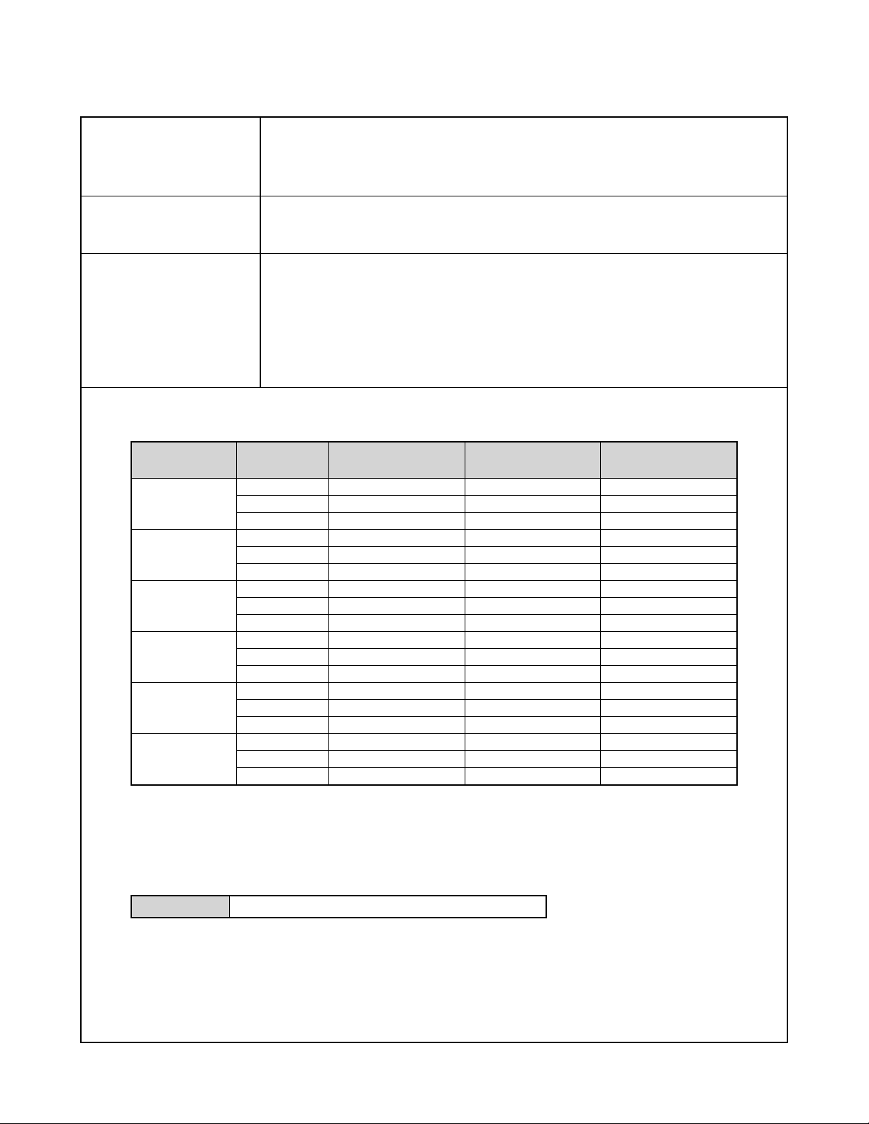
Approximate Memory Capacity and File sizes
• Snapshots
File Size
(pixels)
2560 x 1920
2560 x 1712
(3:2)
2048 x 1536
1600 x 1200
(UXGA)
1280 x 960
(SXGA)
640 x 480
(VGA)
Quality
Fine
Normal
Economy
Fine
Normal
Economy
Fine
Normal
Economy
Fine
Normal
Economy
Fine
Normal
Economy
Fine
Normal
Economy
Approximate Image
File Size
2.2MB
1.8MB
1.3MB
2.0MB
1.6MB
1.1MB
1.6MB
1.2MB
630KB
1.05MB
710KB
370KB
680KB
460KB
250KB
190KB
140KB
90KB
Built-in flash memory
9.3MB
4 shots
4 shots
6 shots
4 shots
5 shots
7 shots
5 shots
6 shots
13 shots
8 shots
12 shots
23 shots
12 shots
19 shots
33 shots
44 shots
58 shots
94 shots
SD Memory Card*
64MB
26 shots
32 shots
44 shots
29 shots
36 shots
51 shots
34 shots
45 shots
88 shots
53 shots
79 shots
154 shots
82 shots
126 shots
221 shots
294 shots
386 shots
618 shots
* Based on Matsushita Electric Industrial Co., Ltd. products. Capacity depends on card manufacturer.
* To determine the number of images that can be stored on a memory card of a different capacity, multiply the capacities
in the table by the appropriate value.
• Movies (320 x 240 pixels)
Data Size 300KB/second max.
— 1 —
Page 4

Delete Single-file, all files (with protection)
Effective Pixels 5.0 million
Imaging Element 1/2.5-inch square pixel color CCD (Total pixels: 5.25 million)
Lens/Focal Distance Lenses Six lenses in five groups, including an aspherical lens
F2.6 (W) to 4.8 (T); f=5.8 (W) to 17.4mm (T) (equivalent to approximately 35 (W)
to 105 (T) for 35mm film)
Zoom 3X optical zoom; 4X digital zoom
(12X in combination with optical zoom)
Focusing Contast-type Auto Focus with AF mode (Spot or Multi AF Area), Macro mode, Pan Focus,
Infinity mode, focus lock, manual focus
Approximate Focus Range Normal 40cm to ∞ (1.3´ to ∞)
(from lens surface) Macro 6cm to 50cm (2.4˝ to 19.7˝)
Exposure Control Light Metering Multi-pattern by CCD
Exposure Program AE
Exposure Compensation –2EV to +2EV (1/3EV units)
Shutter CCD electronic shutter; mechanical shutter, 1/8 to 1/2000 second
• Shutter speed is different for the following BESTSHOT scenes.
Night Scene: 4 to 1/2000 second
Fireworks: 2 seconds (fixed)
Aperture F2.6/4.3, auto switching
White Balance Automatic, fixed (6 modes), manual switching
Sensitivity Auto, ISO 50, ISO 100, ISO 200, ISO 400
Self-timer 10 seconds, 2 seconds, Triple Self-timer
Built-in Flash Flash Modes AUTO, ON, OFF, Red eye reduction
Flash Range Wide Angle Optical Zoom: 0.4 to 2.6 meters (1.3´ to 8.5´)
Telephoto Optical Zoom: 0.4 to 2.0 meters (1.3´ to 6.6´)
(ISO Sensitivity: “Auto”)
Recording Functions Audio snapshot; Macro; self-timer; BESTSHOT; Movie with audio; voice recording
• Audio recording is monaural.
Audio Recording Time Audio Snapshot Approximately 30 seconds maximum per image
Voice Recording Approximately 39 minutes with built-in memory
After Recording Approximately 30 seconds maximum per image
Monitor Screen 2.0-inch TFT color LCD
84,960 pixels (354 x 240)
Viewfinder Monitor screen and optical viewfinder
Timekeeping Functions Built-in digital quartz clock
Date and Time Recorded with image data
Auto Calendar To 2049
World Time City; Date; Time; Summer time;
162 cities in 32 time zones
Input/Output Terminals Cradle connector
Microphone Monaural
Speaker Monaural
— 2 —
Page 5
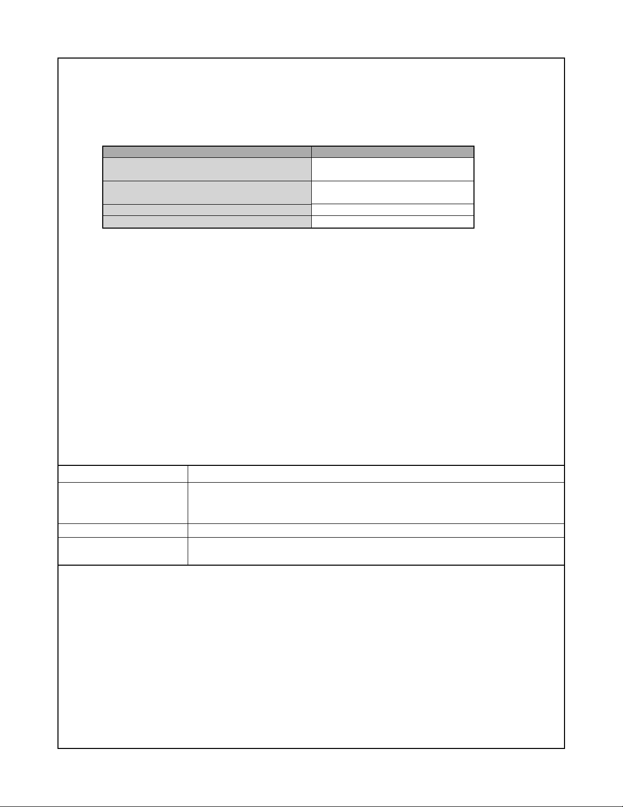
Power Requirements
Power Requirements Rechargeable lithium ion battery
(NP-40) x 1
Approximate Battery Life:
The values below indicate the amount of time under the conditions defined below, until power automatically turns off due to battery
failure. They do not guarantee that you will be able to achieve this level of operation. Low temperatures shorten battery life.
Operation
Number of Shots (CIPA Standard)*
1
(Operating Time)
Number of Shots, Continuous Recording*
(Operating Time)
Continuous Snapshot Playback*
Continuous Voice Recording*
3
4
2
Apporoximate Battery Life
390 shots
(195 minutes)
970 shots
(190 minutes)
380 minutes
350 minutes
Supported Battery: NP-40 (Rated Capacitance: 1230mAh)
Storage Medium: SD Memory Card
*1 Number of Shots (CIPA Standard)
• Temperature: 23°C (73°F)
• Monitor Screen: On
• Zoom operation between full wide to full telephoto every 30 seconds, during which two images are recorded, one image
with flash; power turned off and back on every time 10 images are recorded.
*2 Continuous Recording Conditions
• Temperature: 23°C (73°F)
• Monitor screen: On
• Flash: Off
• Image recorded every 12 seconds, alternating full wide-angle and full telephoto zoom
*3 Continuous Snapshot Playback Conditions
• Temperature: 23°C (73°F)
• Scroll one image about every 10 seconds
*4 Voice recording times are based on continuous recording.
Power Consumption 3.7V DC Approximately 3.0W
Dimensions 87(W) x 57(H) x 22.4(D) mm
(3.4˝(W) x 2.2˝(H) x 0.88˝(D))
(excluding projections; 19.7mm (0.78˝) at thinnest part)
Weight Approximately 121 g (4.3 oz) (excluding battery and accessories)
Bundled Accessories Rechargeable lithium ion battery (NP-40); USB cradle (CA-24); Special AC adaptor; AC
power cord; USB cable; Strap; CD-ROM; Basic Reference
— 3 —
Page 6

Rechargeable Lithium Ion Battery (NP-40)
Rated Voltage 3.7 V
Rated Capacitance 1230 mAh
Operating Temperature
Range 0°C to 40°C (32°F to 104°F)
Dimensions 38.5(W) x 38.0(H) x 9.3(D) mm (1.53˝(W) x 1.50˝(H) x 0.37˝(D))
Weight Approximately 34 g (1.2 oz)
USB Cradle (CA-24)
Input/Output Terminals Camera connector; USB port; AC adaptor terminal (DC IN 5.3V)
Power Consumption 5.3V DC Approximately 3.2W
Dimensions 103(W) x 32(H) x 70(D) mm (4.1˝(W) x 1.3˝(H) x 2.8˝(D)) (excluding projections)
Weight Approximately 71 g (2.5 oz)
Special AC Adaptor (Inlet Type) (AD-C51G)
Power Requirement 100 to 240V AC, 50/60Hz, 83 mA
Output 5.3V DC, 650 mA
Dimensions 78(W) x 20(H) x 39(D) mm (3.1˝(W) x 0.8˝(H) x 1.5˝(D)) (excluding projections and cable)
Weight Approximately 90 g (3.2 oz)
Special AC Adaptor (Plug-in Type) (AD-C51J)
Power Requirement 100 to 240V AC, 50/60Hz, 83mA
Output 5.3V DC, 650mA
Dimensions 48(W) x 16(H) x 69(D) mm (1.9˝(W) x 0.6˝(H) x 2.7˝(D)) (excluding projections and cable)
Weight Approximately 95 g (3.6 oz)
Power Supply
• Use only the special NP-40 rechargeable lithium ion battery to power this camera. Use of any other type of battery is not
supported.
• This camera does not have a separate battery for the clock. The date and time settings of the camera are cleared
whenever power is totally cut off (from both the battery and USB cradle). Be sure to reconfigure these settings after
power is interrupted.
LCD Panel
• The LCD panel is a product of the latest LCD manufacturing technology that provides a pixel yield of 99.99%. This means
that less than 0.01% of the total pixels are defective (they do not turn on or always remain turned on).
Lens
• You may sometimes notice some distortion in certain types of images, such as a slight bend in lines that should be
straight. This is due to the characteristics of lens, and does not indicate malfunction of the camera.
— 4 —
Page 7
Lithium
Ion Battery
AUDIO_IC
8bit_Micon
LCD / BL
Vcc3.3-1
Vcc5-2 Vcc3.3-1
Vcc15 Vcc3.3-1
Vcc15
MICBIAS
Vcc5-2
Vcc1.5 Vcc1.8
27MHz 24MHz
Vcc3.3-1
Vcc3.3-1
EVcc3.3
EVcc3.3
RESET
32.768KHz
10MHz
Vcc1-1
CRDI SW
DGND
DC
CHARGE
CHGCTL
BATTEMP
D+/D - VBUS
Vcc3.3-1
Vcc3.3-1
Vcc3.3-1
VEE7.5C
Vdr
VCCD
VEE7.5C
VCCD
Vcc1.5
Vcc1.8
Vcc3.3-1
Vcc3D
Vcc5-1
Vcc5-2
Vcc5-3
Vcc15
VEE7.5
EVcc3.3
BAT+
+
–
TH
GND1
PWCTL 0 ~ 3
32.768KHz
EVcc3.3
Vcc1-1 Vcc5-3
Connector
Connector
CN-PCB
Connector
RTC
Connector
SIP
CXD3440
CXD3440
Connector
MIC
R LED
G LED
SELF LED
SP
Connector
CDS
CCD
Connector
Connector
Connector
Connector
RECPLAY
POWER
SHUT
DISP
MENU
LEFT
ZOOM+ ZOOM–
RIGHT
DOWN
PLAY
UP
LENS_UNIT
Motor_FPC
MOTOR
DRIVER
CCD_FPC
SD_CARD_
CONNECTOR
POWER_BLOCK
KEY BLOCK
BACK_UP_C
STROBE
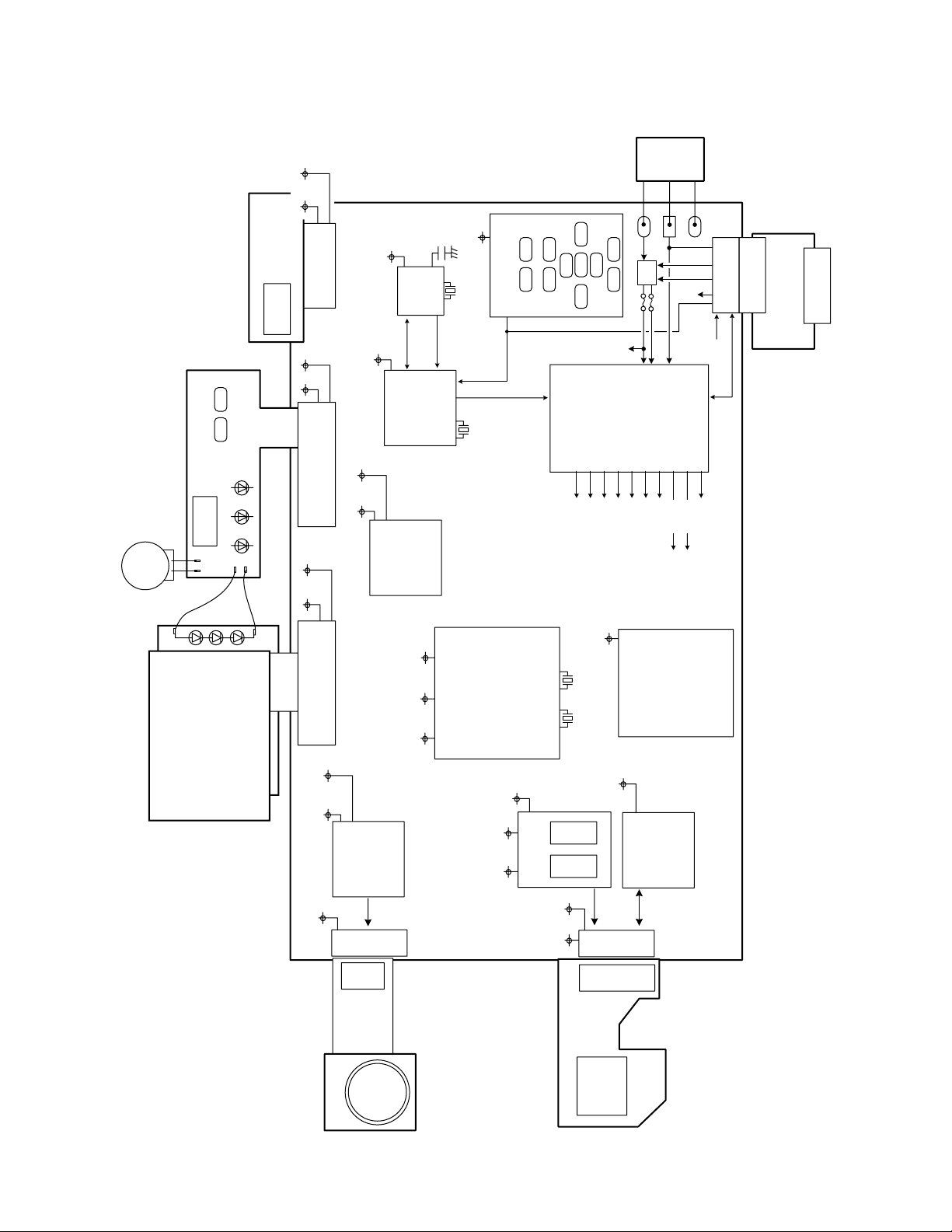
2" – LCD
BLOCK DIAGRAM
— 5 —
Page 8
TEST MODE
Note: Never perform the menu items unless otherwise instructed. Doing so may cause destruction
of the data inside, which will make the camera unusable.
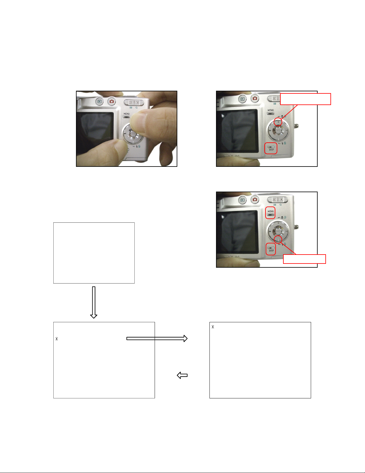
■ To boot the test mode
1. While firmly pressing down both [DISP] and [UPPER], turn the power on.
[UPPER] button
2. After the version appears, press buttons in the order of [DOWN], [DOWN], [DISP] and [MENU] in 0.5
second. The diagnostic menu appears.
Ver 1.00
++ KX879 ++
"DOWN" button -> "DOWN" button -> "DISP" button -> "MENU" button
1 :VERSION INFO
2 :VIDEO OUT
3 :USB TCC TEST
4 :TEST MENU
5 :SOUND TEST
6 :IMAGE FLAG
7 :ROM UPDATE
8 :ADJ TEST
9 :REC-INFO
10 :TEST SCRIPT
11 :LAST MEMORY
12 :FORMAT
"SET" button
"MENU" button
[DOWN] button
1 :USB TCC ON
2 :USB TCC OFF
3 :USB STORAGE
— 6 —
Page 9

PROGRAM VERSION UPGRADING
1. To update the firmware version
1. Prepare the memory card which contains the firmware for EX-Z50 in the root directory.
EX-Z50.bin
2. Insert the above memory card into the camera, and set a fully charged battery in the camera.
3. Press the [power button] while holding [MENU] depressed. Keep holding [MENU] depressed until
“PROGRAM UPDATE” appears in the display.
• The following appears.
• The version of the firmware in the memory card appears at the bottom of the display.
NOTE 1) When a wrong software is mistakenly used,
PROGRAM UPDATE
YES
NO
NEW VERSION IS
VER 1.00
(As of November 2004)
the message below appears. Update the
firmware again with the correct software.
FILE ERROR!
0x1002
NOTE 2) When only the version appears in the display
even though you are trying to operate the
camera, charge the battery to the fullest and
try again. The level of the battery indicator
should be highest in order to update the
firmware.
4. Align the white cursor to [YES] by [쑿] and [쑼], and then press [SET].
• “NOW LOADING” appears in the display and the update starts.
5. “COMPLETE” appears after the update finishes.
6. Remove the memory card after turning the power off once. Turn the power back on again while holding
[MENU] depressed, and check the version.
• “VER.1.00” appears.
VER 1.00
(As of November 2004)
7. If the version is correct, turn the power off.
8. Finally, check the operation by recording, playing back and deleting an image.
— 7 —
Page 10

2. How to restore the firmware
1. Prepare the firmware restoration program and change its name as follows;
“rom879-041126.lbn” 씮 “jupiter.bin”
NOTE: This software and procedure automatically restores the firmware even if the firmware belongs
to a wrong model code. Make sure to use the correct software for the correct model.
2. Copy the above file to the root directory in the memory card.
3. Insert the memory card into the camera.
4. Set a fully charged battery in the camera.
NOTE: This software and procedure automatically restores the firmware even if the battery capacity of
the camera is low. Make sure to use a fully charged battery to prevent the danger of power
down during firmware restoration.
5. Turn the power on while pressing the [shutter release] button.
If the power does not turn on only by pressing the power button, insert the battery while holding the
[shutter release] button depressed.
• The LED next to the optical viewfinder changes from “green/red blinking”, “green blinking” to “green steady”.
NOTE: This software and procedure automatically restores the firmware even if the firmware belongs
to a wrong model code. Make sure to use the correct software for the correct mode.
6. When the LED becomes “green steady”, the firmware restoration is finished.
Remove the battery and the memory card, and then turn the power off.
7. Turn the power on again while holding [DISP] and [UPPER] depressed.
Check the model name and the program version (PR:) in the opening screen of the test menu.
++KX879++
Ver 1.00
8. If the model name and the program version are correct, perform SYSTEM INITIAL to initialize the
system area.
“DISP+ UPPER + PW ON” 씮 “DOWN, DOWN, DISP, MENU” 씮 “7:ROM UPDATE” 씮 “5:SYSTEM
INITIAL”
NOTE: After SYSTEM INITIAL is performed, “SYSTEM ERROR” appears when the power is turned
on again.
9. Write the latest firmware.
After the firmware is written, check the model name and the program version (PR:) in the opening
screen of the test menu.
10. Finally, start the camera normally to check the operation by recording, playing back and deleting an
image. Check also that the colors in the images are not too bright or two dark.
— 8 —
Page 11

3. To install the firmware
Initially, firmware is not installed in the PCB supplied by the parts center.
Install the firmware into the PCB after replacing with a new one as shown in the procedures below.
NOTE: The camera does not operate (only LED becomes “green blinking”) if the firmware is not installed
in the PCB.
<Writing the restoration program 1>
1. Copy the following software to the root directly of the SD card.
Restoration software: rom879-041126.lbn
Firmware: EX-Z50.bin
2. Change the name as follows;
“rom879-041126.lbn” to “jupiter.bin”
3. Insert the SD card into the camera.
4. Insert the battery while holding the [shutter release] button depressed.
The LED next to the optical viewfinder changes from “green/red blinking”, “green blinking” to “green
steady”.
5. When the LED becomes “green steady”, remove the battery and turn the power off.
<System Initialize>
1. Boot the test mode.
2. Press [DOWN] twice and then press [DISP], [MENU].
3. Select “7: ROM UPDATE” and then press [SET].
4. Select “5: SYSTEM INITIALIZE” and then press [SET].
5. When the following message appears, press [SET].
SYSTEM INITIALIZE
START….
PUSH OK KEY?
6. The system initialize is executed. Turn off the power when “SUCCESS” appears.
* “SYSTEM ERROR” appears when the camera is turned off without system initialize.
<Writing the firmware>
1. Turn the power on while holding [MENU] depressed.
2. When “PROGRAM UPDATE” appears, select “YES” and then press [SET].
3. “NOW LOADING” appears while the firmware is updated.
4. When “COMPLETE” appears, the firmware update is complete.
5. Turn the power on and off to check if the camera normally functions. If there is no problem, the firmware
update is successful.
— 9 —
Page 12

ADJ TOOL
■ Introduction
Make sure to perform the adjustment by the USB ADJ Tool “adj03SSAW.exe” when replacing the lens
unit or the PCB.
Here the necessary software, driver and setting are explained to use “adj03SSAW.exe”.
Note that the tool, drivers etc. are available only for Windows.
1. Preparation
1-1. Prepare the necessary software, driver and DLL file.
1) Prepare the following three files.
• Common test driver for CASIO/PENTAX
[testmode_pentax_casio] folder uusbd.dll
uusbd.inf
uusbd.sys
• ADJ tool, USB DLL and ADJ setting file
[adj03SSAW] folder adj03SSAW.exe (ADJ tool itself)
uusbd.dll (USB DLL)
*.adt (ADJ setting file. Sorted by models)
* Place all files in the same folder.
2) Place the common test driver for CASIO/PENTAX in an appropriate place.
3) Place all of ADJ tool, USB DLL and ADJ setting file in the same folder.
1-2. Set the camera so that it recognizes the USB test mode.
1) Enter the test menu.
Turn the power on while pressing both [DISP] and [UPPER].
Press [DOWN], [DOWN], [DISP] and [MENU].
2) Move the cursor to “3: USB TCC TEST” and press [SET].
3) Move the cursor to “1: USB TCC ON” and press [SET].
4) The USB test mode flag is now saved in the camera. Turn the power off.
5) When the USB test mode flag is ON, the test menu appears first when the camera power is turned on.
* When turning the USB test mode flag OFF, set “2: USB TCC OFF” in the test menu.
1-3. Install the USB driver for the USB test mode in the computer.
(The following is an example using the Windows Me.)
1) Prepare the USB driver for the USB test mode.
2) Turn the camera power on which is set in the USB test mode as shown in 1-2 and let it enter the USB
test mode directly (the test menu appears right after the power is turned on).
3) Connect the camera in the above status to the computer by the USB cable.
4) The “Add new hardware” wizard appears.
5) Check “Designate the place for the driver (for users with sufficient knowledge)” and press “Next”.
6) Check “Search for the optimum driver for the device (recommended)”.
7) Check “Designate the place to search”, designate the place which contains “inf” file in the driver by
pressing “Reference” button, and then press “Next” button.
8) When “Universal USB Driver (VMEM manufacturer’s name)” appears upon message “Searching for
the driver file for the following devices”, press “Next” button.
— 10 —
Page 13

9) The file copy starts.
(If a message “uusbd.inf cannot be found” appears during the file copy, designate the same place as
in the step 7).
10) Press “Complete” button.
11) Right-click “My computer”, select “property”, and then open “Device manager”.
If “Universal USB Driver (VMEM manufacturer’s name)”,“USB device for UUSBD” can be found, the
computer has successfully recognized the driver.
12) The test driver can be used for both CASIO/PENTAX. Installing the test driver into either one enables
the other one to recognize it.
* How to uninstall the USB driver for the USB test mode
• Connect the camera to the computer while in the USB test mode so that the computer recognizes
the camera.
• Right-click “My computer”, select “Property” and open “Device manager”.
• Select “USB device for UUSBD” , and then “Universal USB Driver (VMEM manufacturer's name)”.
• Press “Delete” button to delete the driver.
• When using Windows98/98SE/Me, delete the following three files;
(NOTE! Do NOT delete “usbd.inf” and “usbd.sys”, whose names are much alike the following.)
C:windows / inf / uusbd.inf
C:windows / inf / other / KashiwanoUUSBD.inf
C:windows / system32 / drivers / uusbd.sys
• The driver has been successfully deleted.
1-4. Use the USB ADJ Tool
1) Prepare ADJ tool, USB DLL and ADJ setting file in the same folder.
2) Turn the camera power on which is set in the USB test mode and let it enter the USB test mode directly
(the test menu appears right after the power is turned on).
3) Boot “adj03SSAW.exe” and use it as follows;
• To read ADJ data from the camera
앶앸 Press “READ ($9)”.
There is no need to set the model by “FW Item Set”.
• To write ADJ data into the camera
앶앸 Press “WRITE ($8)”.
• To save ADJ data which is read
앶앸 Select “File” and “Save All ADJ”, and save it under an appropriate name.
• Open ADJ data which is saved
앶앸 1. Select the model by "FW Item Set", and then press "Load FW ->" button.
2. Select “File” and “Open”, and open the necessary file.
• Language” radio button can switch the language between Japanese and English in which the name
of the ADJ ITEM is displayed.
•“Radix” radio button can switch the data display between decimal and hexadecimal notations.
— 11 —
Page 14

2. How to use ADJ Tool when replacing Lens unit
Make sure to perform the following procedure after replacing the lens.
A floppy disk with the lens data is bundled in the spare parts of the lens unit.
1 Enter the TEST mode.
1. Turn the power on while pressing both "DISP" and "UP" buttons.
2. Press "DOWN" button, "DOWN" button, "DISP" button, and "MENU"
button while the program version is displayed.
3. Select "3.USB TCC TEST", and press "SET" button.
4. Select "1. USB TCC ON", and press "SET" button.
5. Turn the power OFF.
2 Connect the camera to the computer by the USB cable.
3 Boot "adj03ssaw" .
4 Select the model name and click "Load FW " Key.
• EX-Z50 앶앸 Kx879
5 Click "ADJ ALL READ", and display the data on the "adj03ssaw".
6 Find the No.1163, "V-COM DC".
7 Write down this value(data).
8 Replace the Lens unit.
9 Perform the above 1 to 3.
6
4
0 Select the model name and click "Load FW " Key.
• EX-Z50 앶앸 Kx879
A From "File/Open", open the bundled floppy disk, and transfer the data to
the "adj03ssaw".
B Find the No.1163,"V-COM DC"
C Change the data to the former value.(Refer to 7).
D Click "WRITE" button of "ADJ ALL".
E After adjustment, change "1. USB TCC ON" to "2. USB TCC OFF".
A
D
— 12 —
Page 15

3. How to use ADJ Tool when replacing MAIN PCB
Firmware is not installed in spare parts.
1 Enter the TEST mode.
1. Turn the power on while pressing both "DISP" and "UP" buttons.
2. Press "DOWN" button, "DOWN" button, "DISP" button and "MENU"
button while the program version is displayed.
3. Select "3.USB TCC TEST", and press "SET" button.
4. Select "1. USB TCC ON", and press "SET" button.
5. Turn the power OFF.
2 Connect the camera to the PC by the USB cable.
3 Boot "adj03ssaw".
4 Select the model name and click "Load FW " Key.
• EX-Z50 앶앸 Kx879
5 Click "ADJ ALL READ", and display the data on the "adj03ssaw".
6 Save the data.
7 Replace the MAIN PCB.
8 Writing the Firmware.
Write the firmware into a spare part after replacing one.
NOTE: If a battery is inserted without the firmware, only LED blinks
green and the camera does not operate.
9 Perform the above 1 to 3.
0 Select the model name and click "Load FW " Key.
• EX-Z50 앶앸 Kx879
A Open the file which is saved above, and display the data on the
"adj03ssaw".
B Click "WRITE" button of "ADJ ALL".
C After adjustment, change "1. USB TCC ON" to "2. USB TCC OFF".
6
5
4
A
B
— 13 —
Page 16

VCOM DC ADJUSTMENT
■ Purpose
Readjust the VCOM value to minimize the flicker of the LCD after replacing the LCD or the main PCB.
■ Necessary tools
1. Camera (Charge its battery fully)
2. Photo diode (S2281-01) : See Fig 1.
3. Photo sensor amp (C2719) : See Fig 2.
4. BNC-BNC cable (E2573) x 2 : See Fig 3.
5. 9-volt alkaline battery (6LR61Y) x 2 : See Fig 4.
6. Oscilloscope
■ Preparation
1. The three tools can be obtained from the following global site.
Photo diode (S2281-01)
Photo sensor amp (C2719)
BNC-BNC cable (E2573)
www.hamamatsu.com/
2. 9-volt alkaline battery is a standard one, but can be obtained from the following global site as well.
www.panasonic.co.jp/global/
Fig1 Photo Diode (S2281-01) Fig2 Photo Sensor Amp (C2719)
Fig3 BNC-BNC Cable (E2573) Fig4 6LR61Y
— 14 —
Page 17

■ Procedure
2:LCD
1:ADJ STAT CLR
3:LENS
.
.
.
1:VCOM OK
.
.
.
OK -> Register Write
VCOM = 0xca
This value is an example and differs by products.
Figure (a)
Figure (b)
Figure (c)
Figure (d)
1 :VERSION INFO
2 :VIDEO OUT
3 :USB TCC TEST
4 :TEST MENU
5 :SOUND TEST
6 :IMAGE FLAG
7 :ROM UPDATE
8 :ADJ TEST
9 :REC-INFO
10 :TEST SCRIPT
11 :LAST MEMORY
12 :FORMAT
1. Camera setting
a) Turn the power on while pressing “DISP” and “UPPER”.
After pressing “DOWN” key twice, press “DISP” and “MENU”.
Figure (a) appears.
b) Select “8 : ADJ_TEST” and then press SET.
(See Figure (b).)
c) Next, select “2. LCD” and then press SET.
(See Figure (c).)
2. Connecting the TOOL
d) Pressing SET causes the right figure to appear.
(See Figure (d).)
a) Place two 9-volt alkaline batteries in C2719.
b)
Connect the output terminal of C2719 to the channel terminal of the oscilloscope by the BNC-BNC cable.
c) Connect the input terminal to the Photo Diode by the BNC cable.
d) Turn the oscilloscope and C2719 on.
* Pull the ON/OFF switch of C2719 this way and raise/lower it. (See below Figure.)
— 15 —
Page 18

3. Measurement
a) Connect S2281-01 to the camera’s LCD monitor (see below).
AC Waveforms appear on the monitor screen of the oscilloscope.
* Change the Rf range of C2719 in case the range does not match.
Photo diode
S2281-01
INPUT OUTPUT
Oscilloscope
Photo sensor amp
CAMERA
BNC-BNC cable
LCD
Minimize the
ripple components
b) After AC waveforms of the oscilloscope appear, minimize it by pressing the camera’s up/down buttons
(see the picture).
Make sure to visually check if it has been minimized.
"Up" button
After it has been minimized, press SET key.
The screen in the right figure appears and the new VCOM
is written (VCOM adjustment is finished.).
Return to the previous display by pressing MENU or PW key.
"Down" button
OK -> Register Write
VCOM = 0xca
ADJ DATA SET!
This value is only an example, and differs by products.
— 16 —
Page 19

CURRENT CONSUMPTION
(1) Current consumption (DC in = 3.70 ~ 4.05 [V])
• Make sure that current consumption is less than 230 mA in PLAY mode.
• Make sure that current consumption is less than 350 mA in REC mode.
• Make sure that current consumption is less than 0.5 mA when power is turned OFF.
(2) The battery indicator changes according to the voltages as follows.
• DC in = less than 3.68 ± 0.05V: (PLAY mode)
• DC in = less than 3.58 ± 0.05V: (PLAY mode)
• DC in = less than 3.43 ± 0.05V: (PLAY mode)
THE COUNTERMEASURE FOR "SYSTEM ERROR"
System error may occur when the battery is removed while data is written to the internal memory.
■ PROCEDURE
1. Initialize the system.
a) Enter the TEST mode.
b) Select "7:ROM UPDATE" and press SET button.
c) Next, select "5:SYSTEM INITIAL" and press SET button.
d) The following message appears.
SYSTEM INITIALIZE
START
PUSH OK KEY?
e) Press SET button and System is initialized.
"SUCCESS !" appears on the monitor.
2. Write firmware.
Refer to the "1. To update the firmware version" on page 7.
Write the firmware.
If the TEST mode boots automatically, change "USB TCC ON" to "USB TCC OFF".
Replace the Main PCB if the camera does not recover.
...
— 17 —
Page 20

DISASSEMBLY
■ Make sure to use correct screws when assembling since
there are several kinds of them.
It is a good idea to sort them as shown in the right when
disassembling.
1. Remove the battery.
■ Removing the case
2. Remove eight screws.
Screws (S1)
3. Remove the front and the rear panels.
Screws (S2)
Screws (S1)
Screws (S2)
— 18 —
Page 21

Note:
Make sure not to damage the lead wire when assembling the rear panel.
Fix the lead wire first when assembling the product.
The rubber key is fixed by the double-sided tape on the rear panel.
■ Removing the LCD
4. Remove one screw and unsolder four lead wires.
Lead wire
Rubber key
Black wire
Red wire
Red wire
Black wire
— 19 —
Page 22

5. Remove the connector, and then the LCD unit.
Connector
■ Removing the PW ASSY
6. Remove the PW ASSY
PW ASSY is fixed by double-sided tape.
7. Remove the connector and then the PW ASSY.
Connector
PW ASSY
— 20 —
Page 23

■ Removing the main PCB
8. Remove two screws.
9. Unsolder three lead wires.
10. Disconnect the connector.
Connector
11. Remove the main PCB.
Wires
Screws (S1)
Connectors
■ Removing the lens unit
12. Remove one screw.
Screw
13. Remove one screw and then the Lens plate.
Screw
Lens plate
— 21 —
Page 24

14. Remove the lens unit.
■ Removing the strobe unit
15. Remove the strobe unit and then the battery frame.
16. Remove one screw and then the strobe unit.
Screw
17. Remove three screws.
18. Remove the tape.
Screws (S4)
Tape
Yellow wire Gray wire
— 22 —
Page 25

19. Remove three battery terminals.
■ Remove tripod screw
20. Remove one screw and then the tripod screw.
Screw (S2)
■ Removing the connector PCB
21. Remove one screw and then the clamp board and the connector PCB.
Screw
■ Disassembling the battery panel
22. Remove the pin and then the battery panel.
Connector PCB
Clamp board
— 23 —
Battery panel
Page 26

■ Assembling the battery panel
1. Extend the sliding part of the battery panel as shown below.
2. Insert the spring.
3. Insert the head of the spring into the battery panel, and then fix it with a pin.
— 24 —
Page 27

28
8
10
9
7
6
11
14
S1
29
30
32
33
S1
S1
S2
S1
S1
S1
S2
S3
S3
2
15
16
17
21
23
31
S4
18
4
3
1
19
20
27
26
25
22
24
5
12
13
EXPLODED VIEW
— 25 —
Page 28

PARTS PRICE LIS
T
EX-Z50
N Item Parts Code Parts Name Specification Price R Remark
N 1 1017 5657 PCB ASSY/MAIN TK-RJK506793*001
2 1017 4235 PW ASSY TK-RJK506753*001
3 1015 3230 PLATE/LENS RJK505783-001V01
N 4 1017 5655 LENS UNIT RJK506744*003 TK
N 5 1017 5659 ST ASSY TK-RJK506751*002
N 6 1017 6898 BADGE/A RJK506869-001V01
N 6 1017 8996 BADGE/B RJK506869-002V01
N 7 1017 6899 TAPE/BADGE RJK506870-001V01
8 1017 4236 PANEL ASSY/CENTER TK-RJK506757*001
N 9 1017 6897 GRIP RJK506868-001V01
10 1015 3163 TAPE/GRIP RJK505787-001V01
N 11 1017 5658 PANEL ASSY/FRONT TK-RJK506746*007
N 11 1017 8757 PANEL ASSY/FRONT TK-RJK506746*008
N 11 1018 1840 PANEL ASSY/FRONT TK-RJK506746*009
12 1015 3232 TAPE/CAM RING RJK505799-001V01
N 13 1017 5253 CAM RING RJK505749-003V02
14 1015 3197 SPRING/BATTERY RJK506102-001V01
15 1015 4306 FRAME/BATTERY RJK505796-001V01
16 1015 4307 FRAME/BATTERY RJK505797-001V01
17 1015 3179 CLAMP BOARD RJK505779-001V01
18 1017 4249 PCB ASSY/CONNECTOR TK-RJK506093*002
19 1015 3178 SHAFT/BATTERY RJK505778-001V01
20 1015 3176 COIL/BATTERY RJK505774-001V01
21 1015 3186 LOCK/BATTERY RJK505764-001V01
N 21 1017 8993 LOCK/BATTERY RJK505764-007V01
N 21 1018 1734 LOCK/BATTERY RJK505764-008V01
22 1015 3185 CASE/BOTTOM RJK505763-001V01
N 22 1017 8992 CASE/BOTTOM RJK505763-007V02
N 22 1018 1733 CASE/BOTTOM RJK505763-008V02
23 1017 0928 SOCK/TRIPOD RJK506765-001V01
N 24 1017 5662 PANEL ASSY/BATTERY TK-RJK506750*007
N 24 1017 8759 PANEL ASSY/BATTERY TK-RJK506750*008
N 24 1018 1842 PANEL ASSY/BATTERY TK-RJK506750*009
25 1015 3187 COIL/BATTERY RJK505773-001V01
26 1015 3177 SHAFT/BATTERY RJK505777-001V01
N 27 1017 5254 LABEL/RATING RJK506755-015V01
N 27 1017 8989 LABEL/RATING RJK506755-017V01
N 27 1018 1727 LABEL/RATING RJK506755-019V01
N 27 1017 5255 LABEL/RATING RJK506755-016V01
N 27 1017 8990 LABEL/RATING RJK506755-018V01
N 27 1018 1728 LABEL/RATING RJK506755-020V01
28 1015 3229 CLAMP BOARD RJK505780-001V01
29 1015 3228 STRAP BOARD RJK505759-001V01
N 30 1017 5656 PANEL ASSY/REAR TK-RJK506747*007
N 30 1017 8758 PANEL ASSY/REAR TK-RJK506747*008
N 30 1018 1841 PANEL ASSY/REAR TK-RJK506747*009
31 1017 4232 LCD ASSY TK-RJK506754*001
32 10153173 KEY UNIT RJK505840-001V01
33 10153174 TAPE/KEY UNIT RJK506073-001V01
S1 1008 1372 SCREW RJK502836-001V01
N S2 1017 8762 SCREW RJK502836-006V01
S3 1015 3183 SCREW RJK502836-003V01
S4 1015 3233 SCREW RJK506113-001V01
QTY
Silver Red Blue Code
111EA
111BV
111AA
111DZ
111CO
100AB
011AB
111DF
111BB
111AN
111AA
100BX
010BX
001CL
111AB
111AR
111AA
111AC
111AD
111AB
111BT
111AA
111AA
100AA
010AA
001AA
100AD
010AD
001AD
111AH
100BK
010BK
001BO
111AA
111AA
100AA
010AA
001AA
100AA
010AA
001AA
111AE
111AB
100CE
010CE
001CN
111DH
111BC
111AD
10 10 10 AA
444AA
222AA
111AA
A
C
X
A FD attached.
C
X
X
X
C
X
X
C
C
C
C
C
C
X
X
X
C
X
X
X
X
X
C
C
C
X
B
B
B
X
X
C For EU/US
C For EU/US
C For EU/US
Except EU/US
C
C Except EU/US
C Except EU/US
X
C
C
C
C
B
C
C
X
X
X
X
- 26 -
Page 29

N Item Parts Code Parts Name Specification Price R Remark
ACCESSORIES
N - 1017 6879 CD ROM CK879DCA01R 1 1 1 AD C
- 1008 5898 USB CABLE UC-K851-CL10 1 1 1 AL C
- 1015 6664 AC CORD CBL-K871-AC-EU 1 1 1 AG C Euro type
- 1015 7018 AC CORD CBL-K871-AC-JU 1 1 1 AH C Blade type
- 1015 7858 AC CORD CBL-K871-AC-UK 1 1 1 AT C UK type
- 1017 1781 AC ADAPTOR AD-C51G-WW-B 1 1 1 BG C *1
- 1017 1780 AC ADAPTOR AD-C51J-WWC-B 1 1 1 BG C *2
- 1017 1787 CRADLE WAU0990-005AE 1 1 1 BY B
- 1015 4950 BATTERY/LI-ION MK11-2632 1 1 1 CP B
- 1013 4888 STRAP ST-K858-Y 1 1 1 AC C
N New Parts
*1 AC cord is not built-in.
*2 Blade type AC cord is built-in.
QTY
Silver Red Blue Code
- 27 -
Page 30

MAIN PCB (TOP VIEW)
PRINTED CIRCUIT BOARDS
— 28 —
Page 31

MAIN PCB (BOTTOM VIEW)
— 29 —
Page 32

MAIN PCB (1/2)
SCHEMATIC DIAGRAMS
— 30 —
Page 33

MAIN PCB (2/2)
— 31 —
Page 34

Ver.1 : Nov. 2004
The program for EX-Z50 has been changed. (P7 ~ P9)
Ver.2 : Jan. 2005
Correction of the EXPLODED VIEW (P25)
Ver.3 : Apr. 2005
Correction of the EXPLODED VIEW (P25)
Ver.4 : Sep. 2005
Correction of the EXPLODED VIEW (P25)
Replacement of the PARTS LIST (P26, P27)
Ver.5 : Dec. 2005
The program for EX-Z50 has been changed. (P8, P9)
CASIO COMPUTER CO.,LTD.
Overseas Service Division
6-2, Hon-machi 1-Chome
Shibuya-ku, Tokyo 151-8543, Japan
 Loading...