

Page 1

EX-V7
INDEX
FEB. 2007
(without price)
■ Spare parts of the LENS UNIT;
1. The lens unit comes with PCB.
2. Replace PCB together with lens unit.
3. Do not use PCB and lens unit together whose serial numbers are not identical.
Serial numbers are labeled on the lens unit and PCB.
Make sure these numbers are identical.
Ver.3 : May. 2007
R
Page 2

CONTENTS
SPECIFICATIONS ....................................................................................................................................... 1
BLOCK DIAGRAM ...................................................................................................................................... 5
TEST MODE ................................................................................................................................................ 6
PROGRAM VERSION UPGRADING .......................................................................................................... 7
1. To update the firmware version ..................................................................................................... 7
2. How to restore the firmware ........................................................................................................... 8
3. To install the firmware .................................................................................................................... 9
ADJ TOOL ................................................................................................................................................. 10
1. Preparation ..................................................................................................................................... 10
2. How to use ADJ Tool when replacing Lens unit ........................................................................ 12
3. How to use ADJ Tool when replacing MAIN PCB ...................................................................... 13
DATA BACKUP OF THE COMPENSATION OF THE HAND MOVEMENT ............................................. 14
VCOM DC ADJUSTMENT ........................................................................................................................ 15
CURRENT CONSUMPTION ..................................................................................................................... 18
THE COUNTERMEASURE FOR "SYSTEM ERROR" ............................................................................. 18
RESETTING THE PLACE OF DESTINATION .......................................................................................... 19
AF ASSIST LAMP ADJUSTMENT ........................................................................................................... 20
DISASSEMBLY ......................................................................................................................................... 21
ASSEMBLY ............................................................................................................................................... 31
EXPLODED VIEW ..................................................................................................................................... 40
PARTS LIST .............................................................................................................................................. 41
PRINTED CIRCUIT BOARD ..................................................................................................................... 43
Page 3
SPECIFICATIONS
Image Files Format Snapshots: JPEG (Exif Version 2.2); DCF (Design Rule for Camera File System) 1.0 standard;
DPOF compliant
Movies:
Audio: WAV
Recording Media Built-in Memory 11.6 MB, SDHC Memory Card, SD Memory Card, MMC (MultiMediaCard),
MMCplus (MultiMediaCardplus)
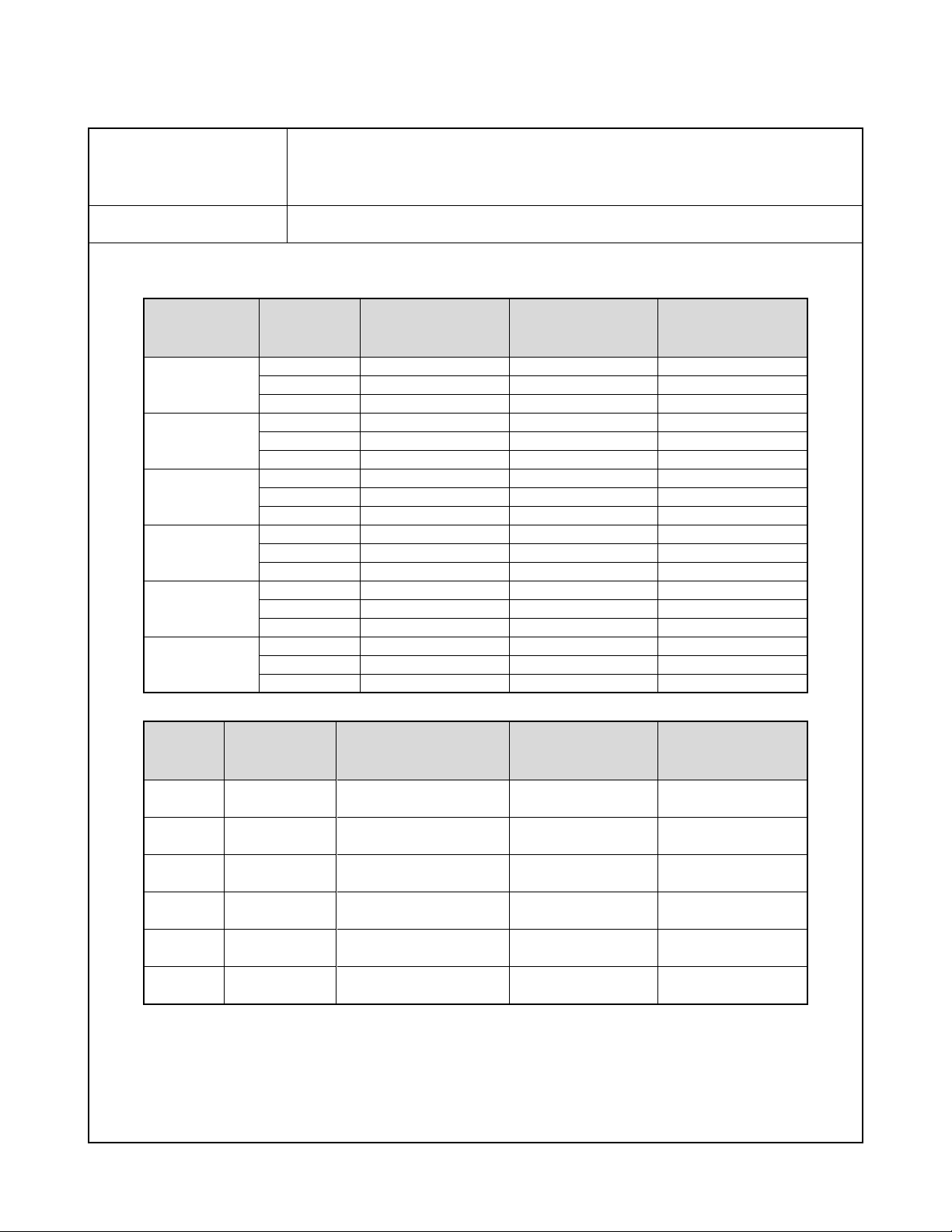
Approximate Memory Capacity and File sizes
• Snapshots
Image Size
(pixels)
7M
3072 x 2304
3:2
3072 x 2048
5M
2560 x 1920
3M
2048 x 1536
2M
1600 x 1200
VGA
640 x 480
Image
Quality
Fine
Normal
Economy
Fine
Normal
Economy
Fine
Normal
Economy
Fine
Normal
Economy
Fine
Normal
Economy
Fine
Normal
Economy
H.264/AVC MOV format (Motion JPEG AVI format when the image quality setting is “LP”)
Approximate Image
File Size
4.3 MB
2.31 MB
1.57 MB
3.73 MB
2.02 MB
1.38 MB
2.99 MB
1.62 MB
1.12 MB
2.0 MB
1.15 MB
720 KB
1.26 MB
790 KB
470 KB
330 KB
190 KB
140 KB
Approximate Built-in
Memory (11.5MB )
Capacity
2 images
5 images
7 images
3 images
5 images
8 images
3 images
7 images
10 images
5 images
10 images
16 images
9 images
14 images
25 images
35 images
61 images
84 images
Approximate SD
Memory Card*
(256MB) Capacity
56 images
105 images
155 images
65 images
120 images
176 images
81 images
150 images
217 images
121 images
211 images
338 images
193 images
308 images
518 images
738 images
1282 images
1740 images
• Movies
Image
Quality
(Pixels)
UHQ
640 x 480
UHQ Wide
848 x 480
HQ
640 x 480
HQ Wide
848 x 480
Normal
640 x 480
LP
320 x 240
* The number of image values are approximate and are provided for reference only. The actual number of images you may be
able to record may be less than that indicated on the monitor screen.
* Image files sizes are approximate and are provided for reference only. Actual image file sizes vary depending on subject type.
* Based on Matsushita Electric Industrial Co., Ltd. products. The number of images you can save depends on the type of memory
card you are using.
* To determine the number of images that can be stored on a memory card of a different capacity, multiply the capacities in the
table by the appropriate value.
Maximum
Recording
Time Per File
10 minutes
10 minutes
10 minutes
10 minutes
10 minutes
10 minutes
Approximate Data Rate
(Frame Rate)
6.0 Megabits / second
(30 frames / second)
7.2 Megabits / second
(30 frames / second)
3.0 Megabits / second
(30 frames / second)
3.6 Megabits / second
(30 frames / second)
1.5 Megabits / second
(30 frames / second)
2.4 Megabits / second
(15 frames / second)
Approximate
Built-in Memory
(11.6MB) Capacity
16 seconds
13 seconds
32 seconds
27 seconds
65 seconds
39 seconds
Approximate
SD Memory Card*
(256MB) Capacity
5 minutes,
35 seconds
4 minutes,
38 seconds
11 minutes,
15 seconds
9 minutes,
21 seconds
22 minutes,
28 seconds
13 minutes,
34 seconds
— 1 —
Page 4

Delete 1 file; all files (with memory protection feature)
Effective Pixels 7.2 million
Imaging Element 1/2.5 square pixel primary color CCD (Total pixels: 7.41 million)
Lens/Focal Distance F3.4 to 5.3/f=6.3 to 44.1 mm(Equivalent to 38 to 266 mm on a 35 mm film camera.)
12 lenses in 9 groups, including aspherical lens.
Zoom 7X optical zoom / 4X digital zoom(Image Size: 7M (3072 x 2304 pixels)) (28X total zoom)
Focusing Contrast Detection Auto Focus
Focus Modes Auto Focus, Macro Focus, Infinity Mode, Manual Focus
AF Area Spot, Multi or Tracking; with AF assist lamp
Approximate Focus Range Auto Focus : 30 cm to ∞ (1.0' to ∞)
(from lens surface) Macro Focus : 10 cm to 40 cm (3.9" to 15.7")
Infinity : ∞
Manual Focus:10 cm to ∞ (3.9" to ∞)
Range is affected by optical zoom.
Exposure Control Metering : Multi-pattern, center weighted, and spot by imaging element
Exposure: Program AE
Exposure Compensation: -2EV to +2EV (in 1/3EV steps)
Shutter CCD shutter, mechanical shutter
Snapshot (Auto): 1/2 to 1/800 second
Snapshot (Manual Exposure/Shutter Speed Priority AE): 60 to 1/800 second
Snapshot (Aperture Priority AE): 1 to 1/800 second
Shutter speed is different for some BEST SHOT scenes.
*
Aperture Value Auto/Shutter Speed Priority AE: F3.4 / F4.6 / F9.2* auto switching
Manual Exposure/Aperture Priority AE: F3.4 / F4.6 / F9.2*
Using optical zoom causes the aperture value to change.
*
F9.2 is the aperture when an ND filter is being used.
*
White Balance Auto, fixed (6 modes), manual
Sensitivity Snapshots (Standard): Auto, ISO64, ISO100, ISO200, ISO400, ISO800
Maximum sensitivity is ISO 1600 when the BEST SHOT “High Sensitivity” scene is being used.
*
Movies: Auto
Self-timer Trigger Times: 10 seconds, 2 seconds, Triple Self-timer
Built-in Flash
Flash Modes Auto, Off, On, Soft Flash, Red-eye reduction
Approximate Flash Range Flash Range:
Wide Angle Optical Zoom: 0.1 to 2.2 meters (0.3' to 7.2')
Telephoto Optical Zoom : 1.0 to 1.4 meters (3.3' to 4.6')
Flash Continuous Shutter
•
Wide Angle Optical Zoom: 0.4 to 2.1 meters (1.3' to 6.9')
Telephoto Optical Zoom : 1.0 to 1.4 meters (3.3' to 4.6')
* ISO Sensitivity: “Auto”
* Depends on zoom factor.
Recording Snapshots (with audio); Macro; Self-timer; Continuous shutter (Normal-speed Continuous Shutter,
High-speed Continuous Shutter, Flash Continuous Shutter); BEST SHOT; easy mode; movie
with stereo audio (Movie, MOVIE BEST SHOT, Short Movie, Past Movie) ; audio (Voice
Recording)
Approximate Audio Audio Snapshot : 30 seconds per image
Recording Times After Recording : 30 seconds per image
Voice Recording: 36 minutes (when using built-in memory)
Monitor Screen 2.5-inch TFT color LCD, 230,400 (960 x 240) pixels
Viewfinder Monitor Screen
Timekeeping Functions Built-in quartz digital clock
Date and Time: Recorded with image data, Time stamp
Auto Calendar : To 2049
World Time 162 cities in 32 time zones
City name, date, time, summer time
Input/Output Terminals Cradle contact
USB USB 2.0 Hi-Speed compatible
Microphone Stereo
Speaker Monaural
— 2 —
Page 5
Power Requirements
Power Requirements Lithium ion rechargeable battery
(NP-50) x 1
Approximate Battery Life:
All of the values provided below represent the approximate amount of time under normal temperature (23°C (73° F)) before the
camera turns off. These values are not guaranteed. Low temperatures shorten battery life.
Number of Shots (CIPA)*
1
Continuous Playback (Snapshots)*
Continuous Movie Recording
Continuous Voice Recording*
3
2
240 shots
360 minutes
100 minutes
260 minutes
• Battery: NP-50 (Rated Capacity: 950 mAh)
• Recording Medium: SD Memory Card
• Measurement Conditions
*1 Number of Shots (CIPA)
In accordance with CIPA standards
Normal temperature (23°C ( 73° F)), monitor on, zoom operation between full wide and full telephoto every 30 seconds, during
which two images are shot with flash; power turned off and back on every time 10 images are shot.
*2 Continuous Playback Time
Standard temperature (23°C ( 73° F)), one-image scroll approximately every 10 seconds
*3 Approximate continuous recording time
• The above values are based a new battery, starting from a full charge. Repeated charging shortens battery life.
• Frequency of flash, zoom, and Auto Focus usage, and the time the camera is on greatly affects recording time and number of
shots values.
Power Consumption
Dimensions
Weight
Bundled Accessories
3.7 V DC; Approximately 4.5 W
95.5
3.8
(
Excluding projections; 20.8 mm (0.8") at thinnest point)
(
(W) ✕
˝(W) ✕
59.8
2.4
(H) ✕
˝(H) ✕
25.5
1.0
(D) mm
˝(D))
Approximately 149 g (5.3 oz)(excluding battery and bundled accessories)
Rechargeable Lithium Ion Battery (NP-50); USB Cradle (CA-35); Special AC Adaptor (AD-C52G)/
AC Power Cord; USB Cable; AV Cable; Strap; CD-ROMs (2); Basic Reference
— 3 —
Page 6

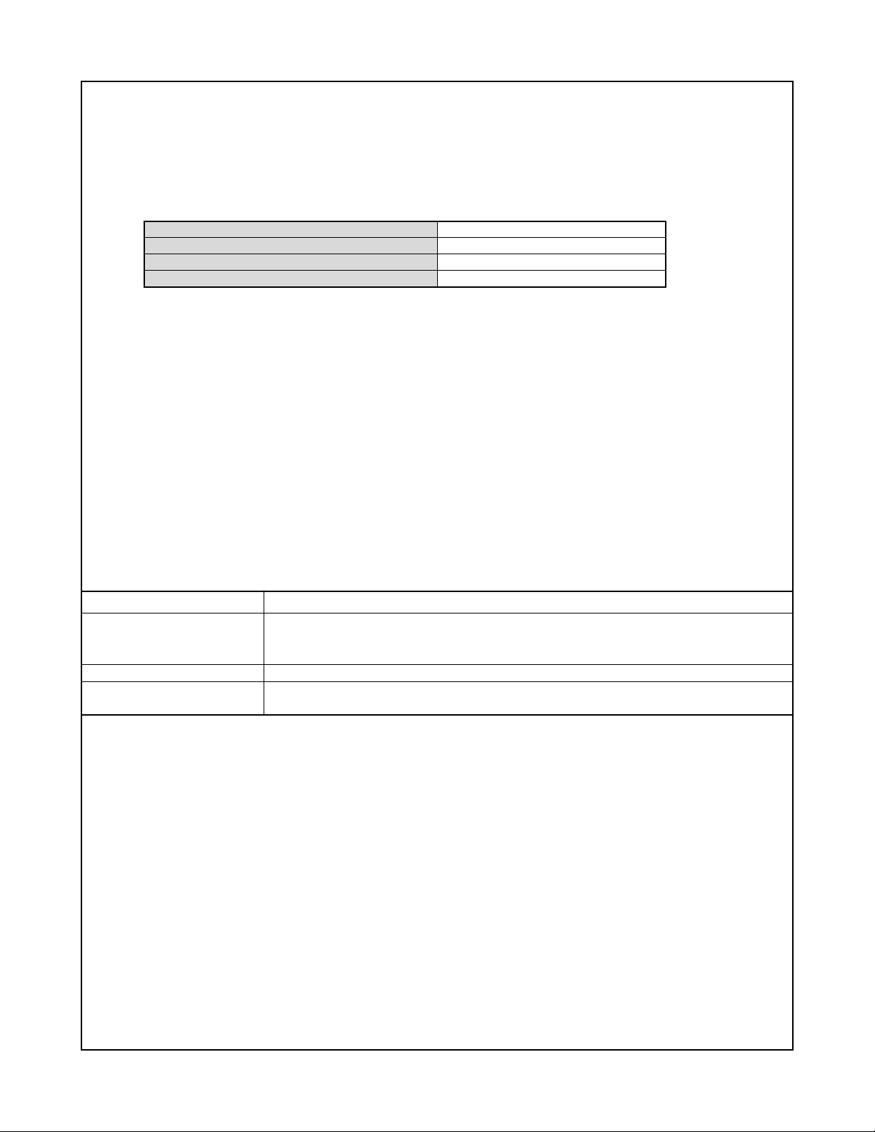
Rechargeable Lithium Ion Battery (NP-50)
Rated Voltage 3.7 V
Rated Capacitance 950 mAh
Operating Temperature 0 to 40°C (32 to 104°F)
Dimensions 23.5 (W) ✕ 70.1 (H) ✕ 7.0 (D) mm(0.93"(W) ✕ 2.76"(H) ✕ 0.28"(D))
Weight Approximately 30 g (1.06 oz)
USB Cradle (CA-35)
Input/Output Terminals Camera contact; USB port; external power supply terminal (DC IN 5.3 V);
AV terminal (AV OUT: NTSC/PAL standards)
Power Consumption 5.3V DC Approximately 3.2W
Dimensions 111 (W) ✕ 30 (H) ✕ 71 (D) mm (4.4"(W) ✕ 1.2"(H) ✕ 2.8"(D)) (Excluding projections)
Weight Approximately 69 g (2.4 oz)
Special AC Adaptor (Inlet Type) (AD-C52G)
Input Power 100 to 240V AC, 50/60Hz, 83mA
Output Power 5.3V DC, 650mA
Dimensions 50 (W) ✕ 20 (H) ✕ 70 (D) mm(2.0"(W) ✕ 0.8"(H) ✕ 2.8"(D)) (Excluding projections and cable)
Weight Approximately 90 g (3.2 oz)
Power Supply
• Use only the special rechargeable lithium ion battery (NP-50) to power this camera. Use of any other type of battery is not
supported.
• The camera does not have a separate battery for the clock. The date and time settings of the camera are cleared about 12
hours after power is totally cut off (from both the battery and USB cradle). If this happens, be sure to reconfigure these settings
after power is restored.
LCD Panel
• The liquid crystal panel of the monitor screen uses high-precision technology that provides a pixel yield in excess of 99.99%.
This means that some pixels may not light or may remain lit at all times. This is due to the characteristics of the liquid crystal
panel, and does not indicate malfunction.
Lens
• Never apply too much force when cleaning the surface of the lens. Doing so can scratch the lens surface and cause malfunction.
• You may sometimes notice some distortion in certain types of images, such as a slight bend in lines that should be straight.
This is due to the characteristics of lens, and does not indicate malfunction of the camera.
Special AC Adaptor
• Power cord precautions for use in Singapore
The power cord set is not supplied. The power cord used must comply with relevant national and/or international standards.
— 4 —
Page 7
Strobe
10PIN
Connector
Strobe Unit PPL
Vcc1-0
Vcc3.3D
10PIN
Connector
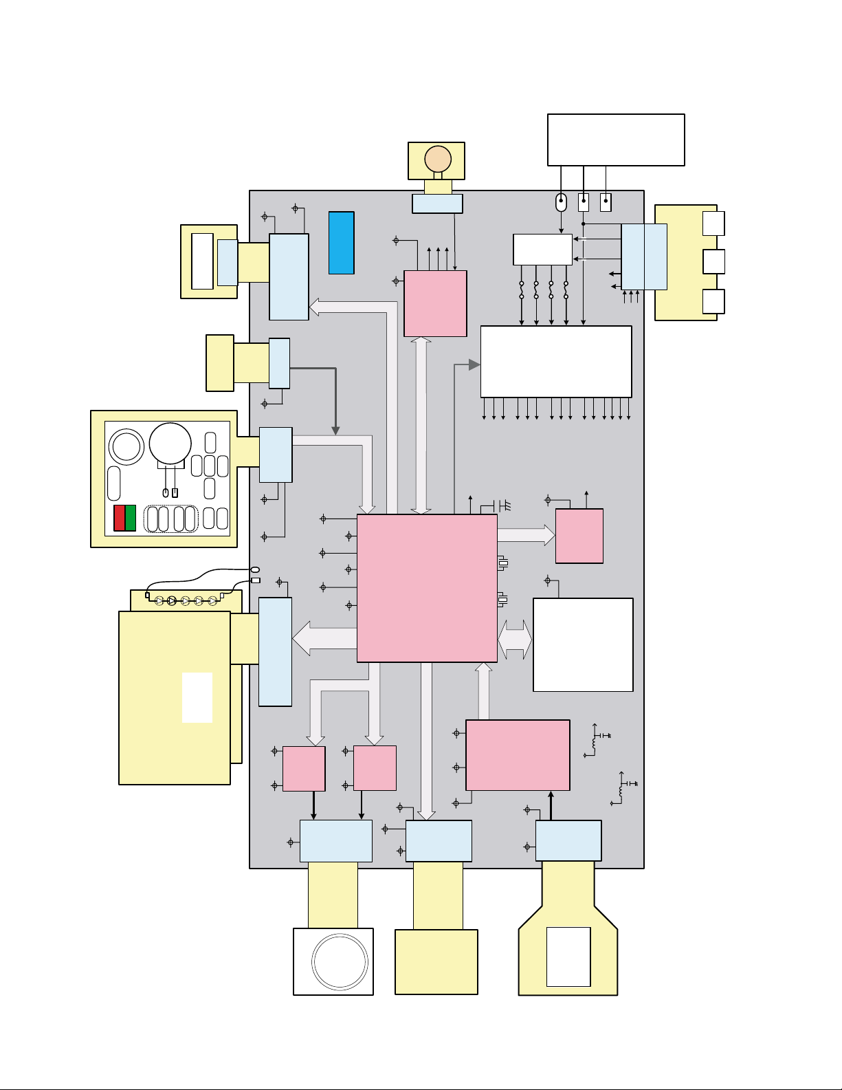
BLOCK DIAGRAM
MIC
Connector
4PIN
LOUT
Speaker
ROUT
MOVIE_LED
Vcc3.3-1 Vcc3.3A
AUDIO IC
AK4646EN
FU103
FU102
BAT+
FU101
+
FU100
BATTERY
(1000mA/h)
TH
-
GND 1
VCC
CHG
DC
USBGND
AGND
D+/D-
30PIN
Connector
Connector
LOUT
VOUT
ROUT
30PIN
A/V
USB
CRADLE
DC
JACK
JACK
JACK
KEY-FPC
KEY
DIAL
SHUTTER
R-LED
G-LED
Speaker
Dynamic
UP
-
+
TELE-H
TELE-L
WIDE-L
WIDE-R
2.5" LCD
LCD/BL UNIT
SW
BARRIER
RIGHT
SET
DOWN
LEFT
PLAY
MENU
5- LED BL
EVcc3.3EVcc3.3
Connector
Vcc3.3D
Vcc3.3D
Connector
Vcc3.3D
Vcc4.3-M
2PIN
Connector
17PIN
37PIN
MOTOR-dr_A
Vcc3.3D
Vcc3.3AEVcc3.3 Vcc1.8
BUS
LCD-
MOTOR-BUS
R2A30405NP
Vcc4.3-M Vcc3.3D
Connector
Vcc3.3DVCCRTC Vcc1.2
29PIN
KEY-BUS
MOTOR-BUS
MOTOR-dr_B
R2A30405NP
Vcc3.3MD
STROBE-BUS
Vcc3.3MD
Vcc3.3MP
AUDIO-BUS
PWCTL0~5
LSI-SiP
R8J30235EBGV
VEE7.5C
AS-BUS
VCC13C
Vcc3.3-1
14PIN
(B to B)
Connector
D+/D-
Vcc1-0
Vcc1-1
Back up Cap
CCD-BUS
Vcc1-3
Vcc4.3-M
Vcc3.3MP
Vcc3.3MD
AV-BUS
(RTC)
Vcc3.3D Vcc3.3A
48MHz 32.769KHz
SD-
BUS
CDS+Vdr
AD9923ABBCZRL
VCC13C VEE7.5C
POWER-BLOCK
Vcc1.2
Vcc1.8
EVcc3.3
Vcc3.3-1
VIDEO IC
NJW1351KK1
SD Card
VEE7.5
27PIN
Connector
VCC13
Vcc3.3A
Vcc3.3D
VOUT
Connector
VEE7.5C
VCC13
VEE7.5
BLLEDA
VCC13C
Lens Unit
KONICA 7x
Motor FPC
— 5 —
AS Unit
KONICA
CCD-FPC
CCD
1/2.5" 7M
ICX629CQZ
Page 8
TEST MODE
Note: Never perform the menu items unless otherwise instructed. Doing so may cause destruction of
the data inside, which will make the camera unusable.
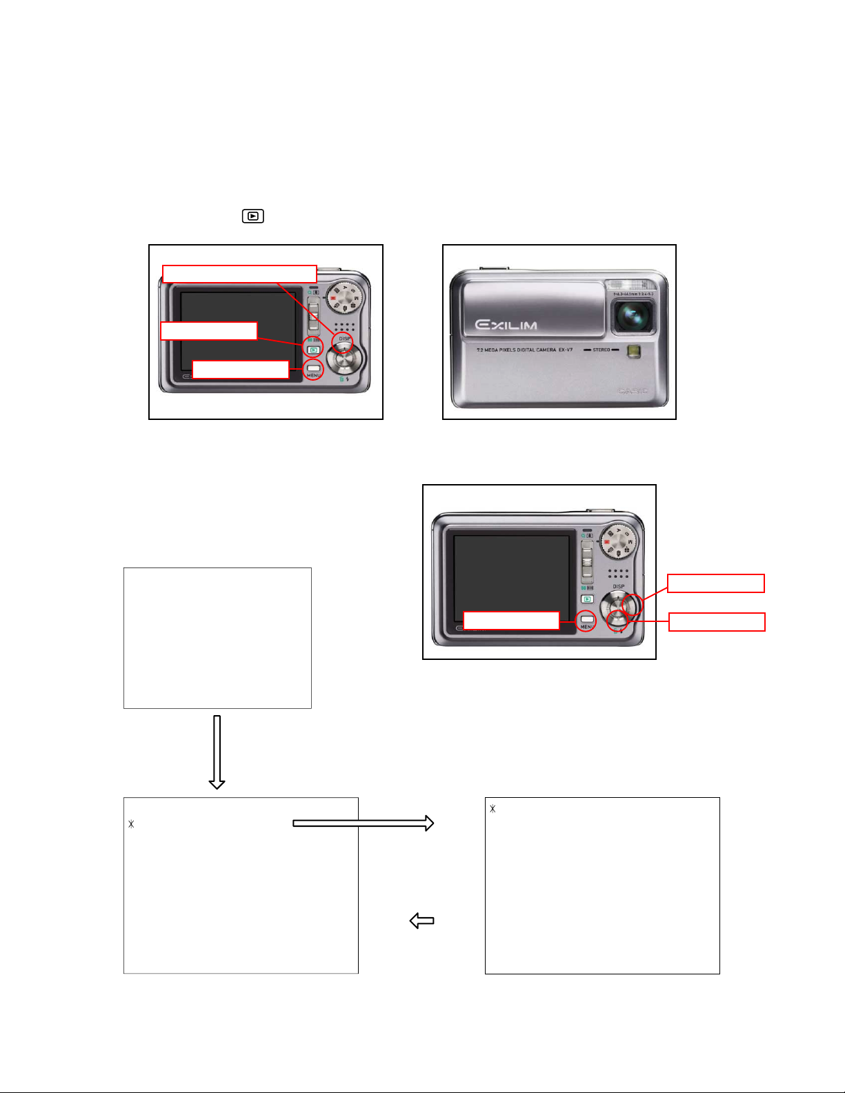
■ To boot the test mode
1. While firmly pressing down both [MENU] and [UPPER (DISP)], turn the power on (Open the lens cover
or push PLAY( ) button .
[UPPER(DISP)] button
[PLAY] button
[MENU] button
2. After the version appears, press buttons in the order of [DOWN], [DOWN], [RIGHT] and [MENU] in 0.5
second. The diagnostic menu appears.
Ver 1.00
++ KX825 ++
"DOWN" button -> "DOWN" button -> "RIGHT" button -> "MENU" button
1 :VERSION INFO
2 :USB TCC TEST
3 :ROM UPDATE
4 :LAST MEMORY
5 :FORMAT
"SET" button
"MENU" button
[MENU] button
1 :USB TCC ON
2 :USB TCC OFF
3 :USB STORAGE
4 :USB SPEED
[RIGHT] button
[DOWN] button
— 6 —
Page 9

PROGRAM VERSION UPGRADING
1. To update the firmware version
1. Prepare the memory card which contains the firmware for EX-V7 in the root directory.
EX-V7.bin
2. Insert the above memory card into the camera, and set a fully charged battery in the camera.
3. Press the [power button] while holding [MENU] depressed. Keep holding [MENU] depressed until
“PROGRAM UPDATE” appears in the display.
• The following appears.
• The version of the firmware in the memory card appears at the bottom of the display.
NOTE 1) When a wrong software is mistakenly used,
PROGRAM UPDATE
YES
NO
NEW VERSION IS
VER 1.00
(As of February 2007)
the message below appears. Update the
firmware again with the correct software.
FILE ERROR!
NOTE 2) When only the version appears in the display
even though you are trying to operate the
camera, charge the battery to the fullest and
try again. The level of the battery indicator
should be highest in order to update the
firmware.
4. Align the white cursor to [YES] by [UPPER] and [DOWN], and then press [SET].
• “NOW LOADING” appears in the display and the update starts.
5. “COMPLETE” appears after the update finishes.
6. Remove the memory card after turning the power off once. Turn the power back on again while holding
[MENU] depressed, and check the version.
• “VER.1.00” appears.
VER 1.00
(As of February 2007)
7. If the version is correct, turn the power off.
8. Finally, check the operation by recording, playing back and deleting an image.
— 7 —
Page 10

2. How to restore the firmware
1. Prepare the firmware restoration program.
uranus.bin
NOTE: This software and procedure automatically restores the firmware even if the firmware belongs
to a wrong model code. Make sure to use the correct software for the correct model.
2. Copy the above file to the root directory in the memory card.
3. Insert the memory card into the camera.
4. Set a fully charged battery in the camera.
NOTE: This software and procedure automatically restores the firmware even if the battery capacity of
the camera is low. Make sure to use a fully charged battery to prevent the danger of power
down during firmware restoration.
5. Turn the power on while pressing the [shutter release] button.
If the power does not turn on only by pressing the power button, insert the battery while holding the
[shutter release] button depressed.
• The LED next to the optical viewfinder changes from “green/red blinking”, “green blinking” to “green
steady”.
NOTE: This software and procedure automatically restores the firmware even if the firmware belongs
to a wrong model code. Make sure to use the correct software for the correct mode.
6. When the LED becomes “green steady”, the firmware restoration is finished.
Remove the battery and the memory card, and then turn the power off.
7. Turn the power on again while holding [MENU] and [UPPER (DISP)] depressed.
Check the model name and the program version (PR:) in the opening screen of the test menu.
++KX-825++
Ver 1.00
8. If the model name and the program version are correct, perform SYSTEM INITIAL to initialize the
system area.
“MENU+ UPPER (DISP) + PW ON” 씮 “DOWN, DOWN, RIGHT, MENU” 씮 “3:ROM UPDATE” 씮
“5:SYSTEM INITIAL”
NOTE: After SYSTEM INITIAL is performed, “SYSTEM ERROR” appears when the power is turned
on again.
9. Write the latest firmware. (Refer to page 7)
After the firmware is written, check the model name and the program version (PR:) in the opening
screen of the test menu.
10. Finally, start the camera normally to check the operation by recording, playing back and deleting an
image. Check also that the colors in the images are not too bright or two dark.
— 8 —
Page 11

3. To install the firmware
Initially, firmware is not installed in the PCB supplied by the parts center.
Install the firmware into the PCB after replacing with a new one as shown in the procedures below.
Note: The camera does not operate (only LED becomes “green blinking”) if the firmware is not installed in
the PCB.
<Writing the restoration software>
1. Copy the following software to the root directly of the SD card.
Restoration software: uranus.bin
Firmware: EX-V7.bin
2. Insert the SD card into the camera.
3. Insert the battery while holding the [shutter release] button depressed.
The LED next to the optical viewfinder changes from “green/red blinking”, “green blinking” to “green
steady”.
4. When the LED becomes “green steady”, remove the battery and turn the power off.
<System Initialize>
1. Boot the test mode.
2. Press [DOWN] twice and then press [RIGHT], [MENU].
3. Select “3: ROM UPDATE” and then press [SET].
4. Select “5: SYSTEM INITIALIZE” and then press [SET].
5. When the following message appears, press [SET].
SYSTEM INITIALIZE
START….
PUSH OK KEY?
6. The system initialize is executed. Turn off the power when “SUCCESS” appears.
* “SYSTEM ERROR” appears when the camera is turned off without system initialize.
<Writing the firmware>
1. Turn the power on while holding [MENU] depressed.
2. When “PROGRAM UPDATE” appears, select “YES” and then press [SET].
3. “NOW LOADING” appears while the firmware is updated.
4. When “COMPLETE” appears, the firmware update is complete.
5. Turn the power on and off to check if the camera normally functions. If there is no problem, the firmware
update is successful.
— 9 —
Page 12

ADJ TOOL
■ Introduction
Make sure to perform the adjustment by the USB ADJ Tool “AdjUSB.exe” when replacing the lens unit or the
PCB.
Here the necessary software, driver and setting are explained to use “AdjUSB.exe”.
Note that the tool, drivers etc. are available only for Windows.
1. Preparation
1-1. Prepare the necessary software, driver and DLL file.
1) Prepare the following three files.
• Testmode driver
[testmode_driver] folder uusbd.dll
uusbd.inf
uusbd.sys
* testmode_driver_2.0] is for Windows except Windows98.
* [testmode_driver] is for Windows98 only.
• ADJ tool, USB DLL and ADJ setting file
[AdjUSB] folder AdjUSB.exe (ADJ tool itself)
uusbd.dll (USB DLL)
* .adt (ADJ setting file. Sorted by models)
2) Place the testmode driver in an appropriate place.
3) Place all of ADJ tool, USB DLL and ADJ setting file in the same folder.
1-2. Set the camera so that it recognizes the USB test mode.
1) Enter the test menu.
Turn the power on while pressing both [MENU] and [UPPER (DISP)].
Press [DOWN], [DOWN], [RIGHT] and [MENU].
2) Move the cursor to “2: USB TCC TEST” and press [SET].
3) Move the cursor to “1: USB TCC ON” and press [RIGHT], [RIGHT] and [SET].
4) USB TCC ON is now active. Turn the power off.
5) The test menu appears first when the camera power is turned on.
* When changing the USB TCC ON to OFF, set “2: USB TCC OFF” in the test menu.
1-3. Install the USB driver for the USB test mode in the computer.
(The following is an example using the Windows Me.)
1) Prepare the USB driver for the USB test mode.
2) Turn the camera power on which is set in the USB test mode as shown in 1-2 and let it enter the USB
test mode directly (the test menu appears right after the power is turned on).
3) Connect the camera in the above status to the computer by the USB cable.
4) The “Add new hardware” wizard appears.
5) Check “Designate the place for the driver (for users with sufficient knowledge)” and press “Next”.
6) Check “Search for the optimum driver for the device (recommended)”.
— 10 —
Page 13

7) Check “Designate the place to search”, designate the place which contains “inf” file in the driver by
pressing “Reference” button, and then press “Next” button.
8) When “Universal USB Driver (VMEM manufacturer’s name)” appears upon message “Searching for
the driver file for the following devices”, press “Next” button.
9) The file copy starts.
(If a message “uusbd.inf cannot be found” appears during the file copy, designate the same place as
in the step 7).
10) Press “Complete” button.
11) Right-click “My computer”, select “property”, and then open “Device manager”.
If “Universal USB Driver (VMEM manufacturer’s name)”,“USB device for UUSBD” can be found, the
computer has successfully recognized the driver.
12) Installing the test driver into either one enables the other one to recognize it.
* How to uninstall the USB driver for the USB test mode
• Connect the camera to the computer while in the USB test mode so that the computer recognizes
the camera.
• Right-click “My computer”, select “Property” and open “Device manager”.
• Select “USB device for UUSBD” , and then “Universal USB Driver (VMEM manufacturer's name)”.
• Press “Delete” button to delete the driver.
• When using Windows98/98SE/Me, delete the following three files;
(NOTE! Do NOT delete “usbd.inf” and “usbd.sys”, whose names are much alike the following.)
C:windows / inf / uusbd.inf
C:windows / system32 / drivers / uusbd.sys
• The driver has been successfully deleted.
— 11 —
Page 14
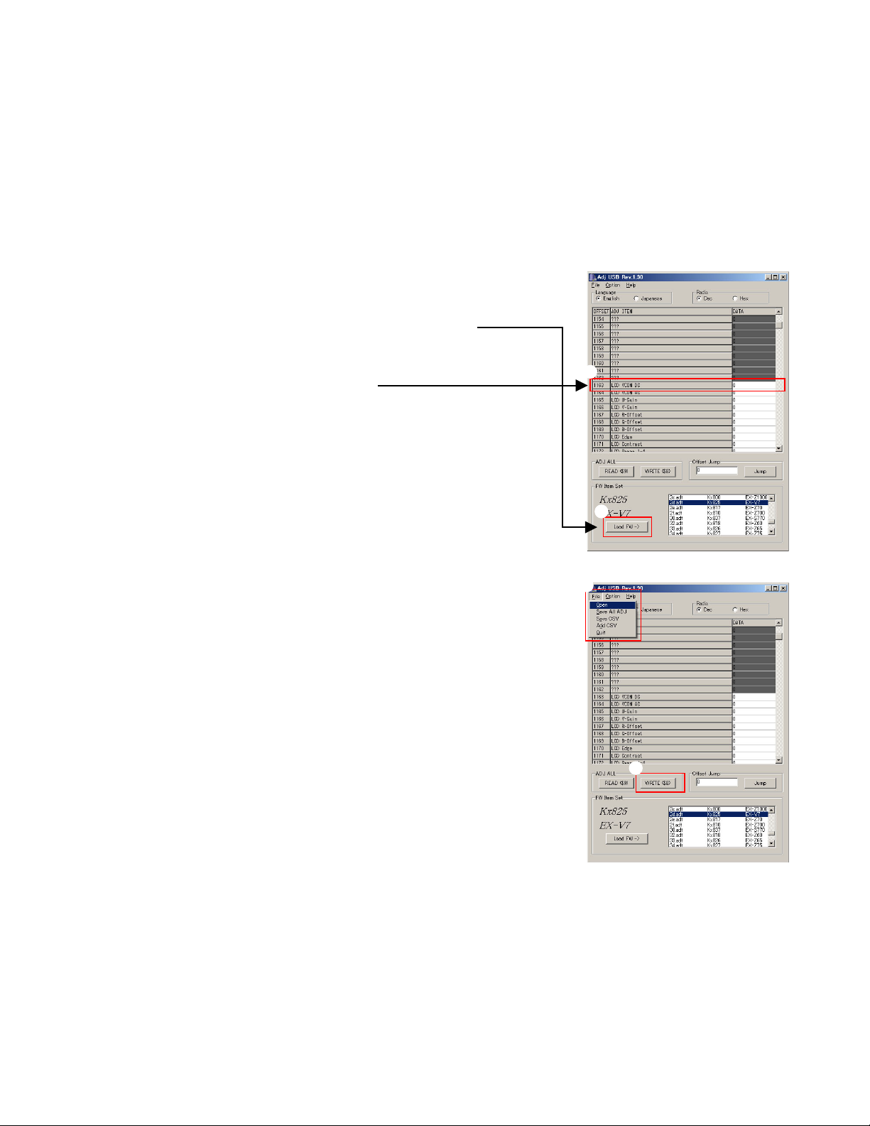
2. How to use ADJ Tool when replacing Lens unit
Make sure to perform the following procedure after replacing the lens.
A floppy disk with the lens data is bundled in the spare parts of the lens unit.
1 Enter the TEST mode.
1. Turn the power on while pressing both "MENU" and "UP" buttons.
2. Press "DOWN" button, "DOWN" button, "RIGHT" button, and
"MENU" button while the program version is displayed.
3. Select "2.USB TCC TEST", and press "SET" button.
4. Select "1. USB TCC ON", and press "RIGHT" button, "RIGHT"
button and "SET" button.
5. Turn the power OFF.
2 Connect the camera to the computer by the USB cable.
3 Boot "AdjUSB" .
4 Select the model name and click "Load FW " Key.
• Kx825 EX-V7
5 Click "ADJ ALL READ", and display the data on the "AdjUSB".
6
6 Find the No.1163, "LCD VCOM DC".
7 Write down this value(data).
8 Replace the Lens unit.
9 Perform the above 1 to 3.
0 Select the model name and click "Load FW " Key.
• Kx825 EX-V7
A From "File/Open", open the bundled floppy disk, and transfer the
data to the "AdjUSB".
B Find the No.1163,"LCD VCOM DC"
C Change the data to the former value.(Refer to 7).
D Click "WRITE" button of "ADJ ALL".
E After adjustment, change "1. USB TCC ON" to "2. USB TCC OFF".
4
A
D
— 12 —
Page 15

3. How to use ADJ Tool when replacing MAIN PCB
Firmware is not installed in spare parts.
1 Enter the TEST mode.
1. Turn the power on while pressing both "MENU" and "UP" buttons.
2. Press "DOWN" button, "DOWN" button, "RIGHT" button and
"MENU" button while the program version is displayed.
3. Select "2.USB TCC TEST", and press "SET" button.
4. Select "1. USB TCC ON", and press "RIGHT" button, "RIGHT"
button and "SET" button.
5. Turn the power OFF.
2 Connect the camera to the PC by the USB cable.
3 Boot "AdjUSB".
4 Select the model name and click "Load FW " Key.
• Kx825 EX-V7
5 Click "ADJ ALL READ", and display the data on the "AdjUSB".
6 Save the data.
7 Replace the MAIN PCB.
8 Writing the Firmware.
Write the firmware into a spare part after replacing one.
NOTE: If a battery is inserted without the firmware, only LED
blinks green and the camera does not operate.
9 Perform the above 1 to 3.
0 Select the model name and click "Load FW " Key.
• Kx825 EX-V7
A Open the file which is saved above, and display the data on the
"AdjUSB".
B Click "WRITE" button of "ADJ ALL".
C After adjustment, change "1. USB TCC ON" to "2. USB TCC OFF".
6
5
4
A
B
— 13 —
Page 16

DATA BACKUP OF THE COMPENSATION OF THE HAND MOVEMENT
Back up the data after replaing the lens or main PCB.
Procedure.
1. Enter the test mode.
a) Turn the power on while pressing both "MENU" and "UP" buttons.
b) Press "DOWN" button, "DOWN" button, "RIGHT" button and "MENU" button while the program version
is displayed.
c) Select "2.USB TCC TEST", and press "SET" button.
d) Select "1. USB TCC ON", and press "RIGHT" button, "RIGHT" button and "SET" button.
2. Select the [8:ADJ TEST] and press SET key.
3. Select the [6:IS] and press SET key.
4. [1:IS BACK UP] is displayed.
5. Press SET key.
6. [IS BACKUP START?] is displayed.
7. Press SET key again.
8. BACKUP finishes if OK is displayed.
9. Turn the power off.
— 14 —
Page 17

VCOM DC ADJUSTMENT
■ Purpose
Readjust the VCOM value to minimize the flicker of the LCD after replacing the LCD or the main PCB.
■ Necessary tools
1. Camera (Charge its battery fully)
2. Photo diode (S2281-01) : See Fig 1.
3. Photo sensor amp (C9329) : See Fig 2.
4. BNC-BNC cable (E2573) x 2 : See Fig 3.
5. 9-volt alkaline battery (6LR61Y) x 2 : See Fig 4.
6. Oscilloscope
■ Preparation
1. The three tools can be obtained from the following global site.
Photo diode (S2281-01)
Photo sensor amp (C9329)
BNC-BNC cable (E2573)
www.hamamatsu.com/
2. 9-volt alkaline battery is a standard one, but can be obtained from the following global site as well.
www.panasonic.co.jp/global/
Fig1 Photo Diode (S2281-01)
Fig2 Photo Sensor Amp (C9329)
Fig3 BNC-BNC Cable (E2573) Fig4 6LR61Y
— 15 —
Page 18

■ Procedure
1. Camera setting
a) Turn the power on while pressing “MENU” and “UPPER”.
After pressing “DOWN” key twice, press “RIGHT” and “MENU”.
Select "2:USB TCC TEST", and press "SET" button.
Select "1:USB TCC ON", and press "RIGHT" button ,"RIGHT"
button and "SET" button.
Figure (a) appears.
Figure (a)
1: VERSION INFO
2: USB TCC TEST
3: ROM UPDATE
4: LAST MEMORY
5: FORMAT
6: HARD TEST
7: IMAGE TEST
8: ADJ TEST
9: TEST SCRIPT
b) Select “8 : ADJ_TEST” and then press SET.
(See Figure (b).)
c) Next, select “2. LCD” and then press SET.
(See Figure (c).)
d) Pressing SET causes the right figure to appear.
(See Figure (d).)
Figure (b)
1: ADJ STAT CLR
2: LCD
3: LENS
.
.
.
Figure (c)
1:VCOM OK
.
.
.
Figure (d)
OK -> Register Write
VCOM = 0xca
This value is an example and differs by products
2. Connecting the TOOL
a) Place two 9-volt alkaline batteries in C9329.
b) Connect the output terminal of C9329 to the channel terminal of the oscilloscope by the BNC-BNCcable.
c) Connect the input terminal to the Photo Diode by the BNC cable.
d) Turn the oscilloscope and C9329 on.
* Pull the ON/OFF switch of C9329 this way and raise/lower it. (See below Figure.)
— 16 —
Page 19

3. Measurement
a) Connect S2281-01 to the camera’s LCD monitor (see below).
AC Waveforms appear on the monitor screen of the oscilloscope.
* Change the Rf range of C9329 in case the range does not match.
Photo diode
S2281-01
INPUT OUTPUT
Oscilloscope
Photo sensor amp
CAMERA
BNC-BNC cable
LCD
Minimize the
ripple components
b) After AC waveforms of the oscilloscope appear, minimize it by pressing the camera’s up/down buttons
(see the picture).
Make sure to visually check if it has been minimized.
[UPPER(DISP)] button
After it has been minimized, press SET key.
The screen in the right figure appears and the new VCOM is
written (VCOM adjustment is finished.).
Return to the previous display by pressing MENU or PW key.
[DOWN] button
OK -> Register Write
VCOM = 0xca
ADJ DATA SET!
This value is only an example, and differs by products.
— 17 —
Page 20

CURRENT CONSUMPTION
(1) Current consumption (DC in = 3.80 ± 0.1 [V])
• Make sure that current consumption is less than 220 mA in PLAY mode.
• Make sure that current consumption is less than 410 mA in REC mode.
• Make sure that current consumption is less than 280 µA when power is turned OFF.
(2) The battery indicator changes according to the voltages as follows.
• DC in = less than 3.72 ± 0.02 V: (PLAY mode)
• DC in = less than 3.62 ± 0.02 V: (PLAY mode)
• DC in = less than 3.54 ± 0.02 V:
(PLAY mode)
THE COUNTERMEASURE FOR "SYSTEM ERROR"
System error may occur when the battery is removed while data is written to the internal memory.
■ PROCEDURE
1. Initialize the system.
a) Enter the TEST mode.
b) Select "3:ROM UPDATE" and press SET button.
c) Next, select "5:SYSTEM INITIAL" and press SET button.
d) The following message appears.
SYSTEM INITIALIZE
START ...
PUSH OK KEY?
e) Press SET button and System is initialized.
"SUCCESS !" appears on the monitor.
2. Write firmware.
Refer to the "1. To update the firmware version" on page 7.
Write the firmware.
If the TEST mode boots automatically, change "USB TCC ON" to "USB TCC OFF".
Replace the Main PCB if the camera does not recover.
— 18 —
Page 21

RESETTING THE PLACE OF DESTINATION
When the main PCB is replaced, the setting of the destination will be changed, therefore resetting is required.
However, when the firmware is changed or fixed, the setting of the destination will be held, therefore resetting
is not required.
Use the destination setting script to change the destination flag as instructed below.
1. Have an SD card ready that have a corresponding script (autorun.scp) under the root directory.
2. Insert the SD card in the camera and turn on the power.
3. If the following messages are shown on the screen after a few seconds, the system finishes changing the
destination flag.
Turn off the camera.
For North America flag: us
For Europe and UK flag: eu
For others flag: asia
4. Remove the SD card from the camera and turn on the power to confirm if the camera is set as you wish
including the number of the menu languages and the scene of the best shot mode.
If there is no problem, the setting is completed.
— 19 —
Page 22

AF ASSIST LAMP ADJUSTMENT
If the lens unit, main PCB or AF assist lamp has been replaced, adjust the AF assist lamp.
1. Preparation
• 18% gray paper (50 cm x 50 cm).
Parts code
94814462
Parts name
GRAY PAPER
Specification
BPS-1305 NO.4
Price coe
DR
• Darkroom or BOX as described below
• Affix the gray paper inside the BOX or darkroom.
2. Procedure
1) Start up in Test mode. (See the Test mode page.)
2) Select "8: ADJ TEST" and press the SET key.
3) Select "4: PICTURE" and press the SET key.
4) Select "7: LED WB" and press the SET key.
5) When "LED WB START?" appears, press the SET key.
6) Position the camera 30 cm from the gray paper and press the shutter button.
3. Block diagram
500mm (H) × 500mm (W) × 400mm (D)
300 ± 50mm
GRAY PAPER
18% gray scale chart
Manufacturer :
Model :
Superior Specialties Inc.
BPS-1305 No.4
EX-V7
— 20 —
Page 23

DISASSEMBLY
Please note that the product on this manual may appear to be different from the actual
one according to the changes such as engineering design change.
* Make sure to use correct screws when assembling since
there are several kinds of them.
It is a good idea to sort them as shown in the right when
disassembling.
Replace the (S6) and (S7) screws with new
ones after being removed. Make sure not to
reuse them.
1. Remove the battery.
■ Removing the CACE
2. Remove two screws and then remove the C-CASE-CA.
Screws (S2)
3. Remove two screws and then remove the C-CASE-BA.
Screws (S1)
— 21 —
Page 24

4. Remove nine screws.
Screws (S3)
5. Removing the front pael assy.
Note: Carefully remove the front pael assy as the lead wires is connected.
Screws (S4)
Screws (S6)
Screws (S5)
Remove the connector.
— 22 —
Page 25

6. Remove the C-CASE-AA.
7. Remove one screw.
8. Release the connector lock and remove one FPC.
Caution: Do not use metal made thin tweezers.
9. Remove the rear pael assy.
Screw (S8)
— 23 —
Page 26

■ Removing the main BR panel assy
11. Open the lens cover in advance.
12. Remove one screw and then remove the plate.
Slide the plate and remove it.
13. Remove one screw.
Close the lens cover.
Screw (S6)
14. Remove three screws and then remove the BR panel assy.
Screws (S6)
SW unit:
Fixed with double-sided tape.
— 24 —
Page 27

■ Removing the KEY unit
15. Remove the KEY unit.
■ Removing the LCD unit
16. Release the connector lock and remove one FPC.
17. Unsolder two lead wires.
18. Remove the tape.
19. Remove the LCD unit.
— 25 —
Page 28

■ Removing the lens PCB
20. Remove the microphone.
Note: Fixed with double-sided tape.
21. Release the connector lock and remove one FPC.
22. Remove two screws and then remove the lens PCB.
Note: It is hooked to the main PCB by the connector on the reverse side of the lens PCB.
Remove the lens PCB by lifting up.
Make sure to ground it PCB before handling.
Screw (S1)
Screw (S1)
Warning:
The lens PCB comes with the lens and the same number as that on lens is labeled to
the lens PCB.
Make sure to replace lens PCB together with lens when replacing lens.
— 26 —
Page 29

■ Removing the main PCB
23. Remove one screws.
24. Release the connector lock and remove two FPCs.
25. Release the connector lock and remove one FPC.
26. Remove the main PCB.
Screw (S1)
27. Remove the microphone.
* It can be removed during step 20 of disassembly procedure.
— 27 —
Page 30

■ Removing the TR-SOCKET/STRAP-BASE/B-COVER
25. Remove the TR-SOCKET
29. Remove one screw, the STRAP-BASE and B-COVER.
Screw (S7)
TR-SOCKET
STRAP-BASE
■ Removing the B-BRACKET
25. Remove the B-BRACKET
Reference drawing
B-COVER
— 28 —
Page 31

■ Removing the lens unit
31. Remove the lens unit.
Hooks
■ Removing the strobe unit
32. Discharge the unit after peeling off the insulating tape.
Caution: Be careful not to short with the frame when you handle the jig.
33. Remove one screw and then remove the strobe unit.
Screw (S8)
— 29 —
Page 32

■ Removing the BS-HOLDER
33. Remove one screw and then remove the BS-HOLDER.
Screw (S8)
— 30 —
Page 33

ASSEMBLY
FOR THE SCREWS WITH A TORQUE VALUE INDICATED, USE A TORQUE DRIVER AND
TIGHTEN IT ACCORDING TO THE VALUE INDICATED ON THE SCREW.
■ Assembling the BS-HOLDER
1. Set the BS-HOLDER and fix it with one screw.
Check point
Screw (S8)
■ Assembling the Strobe unit
2. Set the Strobe unit and fix it with one screw.
Warning
Electrolytic condenser will short out if you place the
strobe light PCB under the frame. Make sure you place
the PCB on the frame.
Check point
Screw (S8)
Check point
OKNG
— 31 —
Page 34

■ Assembling the lens unit
3. Insert the lens unit.
Check point
■ Assembling the TR-SOCKET
4. Set the TR-SOCKET.
TR-SOCKET
■ Assembling the B-BRACKET
3. Set the B-BRACKET.
Note: Set it until it clicks.
Reference drawing
— 32 —
Page 35

■ Assembling the main PCB
6. Install the microphone.
7. Connect the FPC and set the main PCB in.
Note: Make sure to insert the FPC firmly.
8. Assemble with one screw.
9. Insert two FPCs.
Note: Make sure to insert the FPC firmly.
10. Fix the FPC with the tapes.
Screw (S1)
OK NG
— 33 —
Page 36

■ Assembling the lens PCB
11. Insert one FPC.
Note: Make sure to insert the FPC firmly.
12. Set the lens PCB.
Note: Hook it firmly to the connector on the main PCB.
Warning:
The lens PCB comes with the lens.
Confirm that the same number as that
on the lens is labeled on the lens PCB.
13. Assemble with two screws.
14. Install the microphone.
Screw (S1)
Screw (S1)
— 34 —
Page 37

■ Assembling the TR-SOCKET, STRAP-BASE and B-COVER
14. Install STRAP-BASE and B-COVER and fix them by a screw.
STRAP-BASE
Screw (S7)
B-COVER
■ Assembling the LCD unit
15. Lead the FPC and two lead wires through the main body clearance.
16. Insert the FPC.
17. Solder two lead wires.
18. Fix with the tape.
— 35 —
Page 38

■ Assembling the KEY unit
19. Set the KEY unit.
■ Assembling the BR panel assy
20. Set the BR panel assy and fix it with three screws.
21. Open the lens cover.
Assemble with one screw.
Screws (S6)
22. Set the Plate and fix it with one screw.
Screws (S6)
Slide the plate and set in
Screw (S6)
— 36 —
Page 39

■ Assembling the case
23. Set the rear panel assy.
Note: Lead the FPC through the main body clearance.
24. Insert the FPC.
Note: Make sure to insert the FPC firmly.
25. Assemble with one screw.
Screws (S8)
Torque: 8.0 ± 1.0 N•cm
26. Set the C-CASE-AA.
— 37 —
Page 40

27. Connect lead wire of the front panel assy to the main PCB.
28. Set the front panel assy.
29. Assemble with nine screws.
Screws (S4)
Torque: 9.0 ± 1.0 N•cm
Screws (S3)
Torque: 9.0 ± 1.0 N•cm
Screws (S6)
Torque: 9.0 ± 1.0 N•cm
Screws (S5)
Torque: 9.0 ± 1.0 N•cm
— 38 —
Page 41

30. Set the C-CASE-BA and fix it with two screws.
31. Set the C-CASE-CA and fix it with two screws.
Screws (S1)
Torque: 9.0 ± 1.0 N•cm
Screws (S2)
Torque: 9.0 ± 1.0 N•cm
— 39 —
Page 42

EXPLODED VIEW
1
S2B
10
S4
12
9
25
S2
6
11
S7
20
20
7
26
18
S8
8
21
19
16
14
31
15
17
22
S8
24
13
23
S1
S1B
27
28
S6
S1
S1
2
30
3
S6
4
S6
29
5
S6
S6B
S5
S5B
38
— 40 —
37
39
35
34
33
36
S6
S6B
S3
40
32
S3
S5
S5B
Page 43

1 EX-V7_SILVER_DI
2 EX-V7_SILVER_CHINA
3 EX-V7_SILVER_EU
4 EX-V7_SILVER_UK
5 EX-V7_SILVER_US
PARTS LIST
6 EX-V7_BALCK_DI
7 EX-V7_BALCK_CHINA
8 EX-V7_BALCK_EU
9 EX-V7_BALCK_UK
10 EX-V7_BALCK_US
N SpecificationParts NameCode No.Item
N 1 10265774 PANEL ASSY/FRONT TK-RJK509780*001 11111 CPC
N 1 10265775 PANEL ASSY/FRONT TK-RJK509780*002 11111CQC
N 2 10265776 PANEL ASSY/BR TK-RJK509787*001 11111 BRB
N 2 10265769 PANEL ASSY/BR TK-RJK509787*002 11111BUB
N 3 10265184 SW UNIT AMYC1-001A 1111111111AFC
N 4 10265181 SW CABLE RJK509591-001V01 1111111111 ACC
5 10113024 SEAL/DETECTION RJK504361-001V01 1111111111 AAC
N 6 10265266 BATTERY COVER/A RJK509557-001V01 11111 AWC
N 6 10265175 BATTERY COVER/B RJK509557-002V01 11111AZC
N 7 10265772 CASE ASSY/BATTERY TK-RJK509792*001 11111 APC
N 7 10265773 CASE ASSY/BATTERY TK-RJK509792*002 11111 C
N 8 10261618 BRACKET/BATTERY RJK509543*001V01 1111111111 AGX
N 9 10265251 BATERY CASE/A RJK509548-001V01 11111 ADX
N 9 10265253 BATERY CASE/B RJK509548-002V01 11111ADX
N 10 10261625 STRAP BASE/A RJK509560-001V01 11111 ALC
N 10 10265210 STRAP BASE/B RJK509560-002V01 11111 ALC
N 11 10265258 CENTER CASE/CA RJK509554-001V01 11111 AKC
N 11 10265169 CENTER CASE/CB RJK509554-002V01 11111AKC
N 12 10265260 CENTER CASE/AA RJK509556-001V01 11111 APC
N 12 10265171 CENTER CASE/AB RJK509556-002V01 11111AUC
N 13 10265259 CENTER CASE/BA RJK509555-001V01 11111 AMC
N 13 10265170 CENTER CASE/BB RJK509555-002V01 11111APC
N 14 10265232 STROBE UNIT XEST-K825-S 1111111111 BXC
N 15 10265227 TAPE/DOUBLE-SIDED RJK509581-005V01 1111111111AAX
N 16 10265226 TAPE/ST/A RJK509583-001V01 1111111111 AAX
N 17 10265223 TAPE/ST/B RJK509584-002V01 2222222222 AAX
N 18 10265779 LENS UNIT RJK509797*001 TK 1111111111 A*1
N 19 10265221 CUSHION/A RJK509588-001V01 1111111111AAC
N 20 10265222 CUSHION/B RJK509588-002V01 3333333333AAC
N 21 10265224 TAPE/BL RJK509585-001V01 1111111111AAX
N 22 10265233 SPRING/BATTERY/PUSH RJK509842-001V01 1111111111 AAC
N 23 10265225 BS HOLDER RJK509546-001V01 1111111111 ACX
N 24 10261624 SOCKET/A RJK509561-001V01 11111 AIX
N 24 10265219 SOCKET/B RJK509561-002V01 11111 ALX
N 25 10261617 FRAME ASSY RJK509531*001V01 11111 BAX
N 25 10265234 FRAME ASSY RJK509531*002V01 11111 BBX
N 26 10265777 PCB ASSY TK-RJK509791*001 1111111111DQA
N 27 10261620 FRAME/PCB/B RJK509537-001V01 1111111111 AAC
N 28 10261619 FRAME/PCB/C RJK509538-001V01 1111111111 AAC
N 29 10265265 MI C KKM5005-010010 1111111111AWC
N 30 10265261 TAPE/DOUBLE-SIDED RJK509581-006V01 2222222222AAX
N 31 10265214 USB COVER/A RJK509553-001V01 11111 ACC
N 31 10265218 USB COVER/B RJK509553-002V01 11111ACC
N 32 10265770 PANEL ASSY/REAR TK-RJK509781*001 11111 CNC
N 32 10265771 PANEL ASSY/REAR TK-RJK509781*002 11111 C
N 33 10265195 NET/SPEAKER RJK509590-001V01 1111111111 AAC
N 34 10265196 SPEAKER YD1151S-15 1111111111 AHC
N 35 10265194 TAPE/SPEAKER RJK509586-001V01 1111111111AAC
12345678910
Q'TY
Price
Code
R Remarks
N: New parts
*1: PCB and Floppy disk are bundled.
— 41 —
Page 44

1 EX-V7_SILVER_DI
p
p
2 EX-V7_SILVER_CHINA
3 EX-V7_SILVER_EU
4 EX-V7_SILVER_UK
5 EX-V7_SILVER_US
6 EX-V7_BALCK_DI
7 EX-V7_BALCK_CHINA
8 EX-V7_BALCK_EU
9 EX-V7_BALCK_UK
10 EX-V7_BALCK_US
N Item Code No. Parts Name Specification
N 36 10265193 TAPE/DOUBLE-SIDED RJK509581-007V01 1111111111AAC
N 37 10265192 TAPE/DOUBLE-SIDED RJK509581-004V01 2222222222AAC
N 38 10265199 KEY UNIT/A HKW1598-010010-S 11111 BVB
N 38 10265202 KEY UNIT/B HKW1598-010020-S 11111BUB
N 39 10265778 LCD ASSY TK-RJK509782*001 1111111111CYA
N 40 10269591 LABEL/RATING/DBA RJK509778-003V01 1 C For US
N 40 10269592 LABEL/RATING/DCA RJK509778-004V01 1 1 C For EU/UK
N 40 10269593 LABEL/RATING/DFA RJK509778-005V01 1 1 C For DI
N 40 10269594 LABEL/RATING/EFA RJK509778-006V01 1 C
N 40 10269596 LABEL/RATING/DBB RJK509778-008V01 1 C For US
N 40 10269597 LABEL/RATING/DCB RJK509778-009V01 1 1 C For EU/UK
N 40 10269598 LABEL/RATING/DFB RJK509778-010V01 1 1 C For DI
N 40 10269615 LABEL/RATING/EFB RJK509778-011V01 1 C
S1 10203893 SCREW RJK502836-011V01 5555533333 AAC
S1B 10210236 SCREW RJK502836-013V01 22222 AACBlack
N S2 10265264 SCREW RJK509597-002V01 22222 AAC
N S2B 10265167 SCREW RJK509597-003V01 22222 AACBlack
N S3 10265263 SCREW RJK509597-001V01 3333333333 AAC
N S4 10265165 SCREW RJK509595-003V01 2222222222 AAC
N S5 10265262 SCREW RJK509595-001V01 33333 AAC
N S5B 10265168 SCREW RJK509595-002V01 33333 AACBlack
S6 10081372 SCREW RJK502836-001V01 9999977777 AAC
S6B 10194294 SCREW RJK502836-008V01 22222 AACBlack
S7 10190516 SCREW RJK502836-007V01 1111111111 AAC
S8 10086285 SCREW RJK502971-001V01 2222222222 AAC
12345678910
Q'TY
Price
Code
R Remarks
Made
an
in Ja
Made
an
in Ja
FU100 10189325 FUSE FCC10102ABPA 1111111111AAB
FU101 10160169 FUSE FCC10631ABPA 1111111111AAB
N FU102 10265581 FUSE FCC10251ABPA 1111111111AAC
N FU103 10265582 FUSE FCC10751ABPA 1111111111AAC
ACCESSORIES DI C EU UK US DI C EU UK US
N - 10267063 CD RO M CK825DBA01R 1 1 1 1 1 1 AM C For US/DI
N - 10267064 CD RO M CK825DCA01R 1 1 1 1 AM C For EU/UK
N - 10267065 CD RO M CK825DCA02R 1111111111 AMC
- 10252189 A C ADAPTOR AD-C52G-WW-B 1111111111 BCB
- 10233074 A C CORD CBL-K835-AC-CH-06 1 1 AJ C China type
- 10210351 A C CORD CBL-K835-AC-EU-06 1 1 1 1 AF C EU type
- 10210360 A C CORD CBL-K835-AC-TW-06 1 1 AF C Blade type
- 10210354 A C CORD CBL-K835-AC-UK-06 1 1 AR C UK type
- 10250160 A C CORD CBL-K835-AC-US-06 1 1 AH C US type
N - 10263708 AV CABLE AV-K825-BK15 1111111111 APC
N - 10265741 BATTERY/LI-ION MK11-2849 1 1 1 1 1 1 BW B
N - 10267061 BATTERY/LI-ION MK11-2849-C-S 1 1 C D B China only
N - 10267060 BATTERY/LI-ION MK11-2849-U-S 1 1 C D B US only
- 10187367 STRAP ST-K872-S 1111111111 ABX
- 10235765 USB CABLE UC-K815-BK10-MB 1111111111 AIC
N - 10265742 CRADLE WAU0990-013AE 1111111111CDC
N: New parts
— 42 —
Page 45

PRINTED CIRCUIT BOARD
MAIN PCB (TOP VIEW / BOTTOM VIEW)
FU100
FU101
FU103
FU102
— 43 —
Page 46

Ver.1 : Mar. 2007
• Correction of the DISASSEMBLY. (P20, P21, P22, P25, P26, P28)
Ver.2 : Apr. 2007
• Addition of the DATA BACKUP OF THE COMPENSATION OF THE HAND MOVEMENT. (P14)
• Correction of the VCOM DC ADJUSTMENT. (P15, P16, P17)
• Correction of the RESETTING THE PLACE OF DESTINATION. (P19)
• Correction of the DISASSEMBLY. (P31)
Ver.3 : May. 2007
• Correction of the DISASSEMBLY. (P24)
• Correction of the ASSEMBLY. (P31, P36 to P39)
CASIO COMPUTER CO.,LTD.
Overseas Service Division
6-2, Hon-machi 1-Chome
Shibuya-ku, Tokyo 151-8543, Japan
 Loading...