

Page 1
EX-S3
INDEX
MAR. 2003
EX-S3
Page 2

CONTENTS
SPECIFICATIONS ....................................................................................................................................... 1
BLOCK DIAGRAM ...................................................................................................................................... 4
TEST MODE ................................................................................................................................................ 5
PROGRAM VERSION UPGRADING .......................................................................................................... 6
1. How to confirm the program version ............................................................................................. 6
2. How to update the firmware............................................................................................................ 6
3. How to restpre the firmware ........................................................................................................... 7
COLOR ADJUSTMENT .............................................................................................................................. 8
1. How to use USB ADJ Tool .............................................................................................................. 8
2. Lens Replacement ......................................................................................................................... 10
3. MAIN PCB Replacement............................................................................................................... 10
4. Current consumption .................................................................................................................... 11
VCOM DC ADJUSTMENT ........................................................................................................................ 12
THE COUNTERMEASURE FOR "SYSTEM ERROR" ............................................................................. 15
DISASSEMBLY ......................................................................................................................................... 17
EXPLODED VIEW ..................................................................................................................................... 20
PARTS LIST .............................................................................................................................................. 21
PRINTED CIRCUIT BOARDS ................................................................................................................... 22
SCHEMATIC DIAGRAMS ......................................................................................................................... 24
Page 3
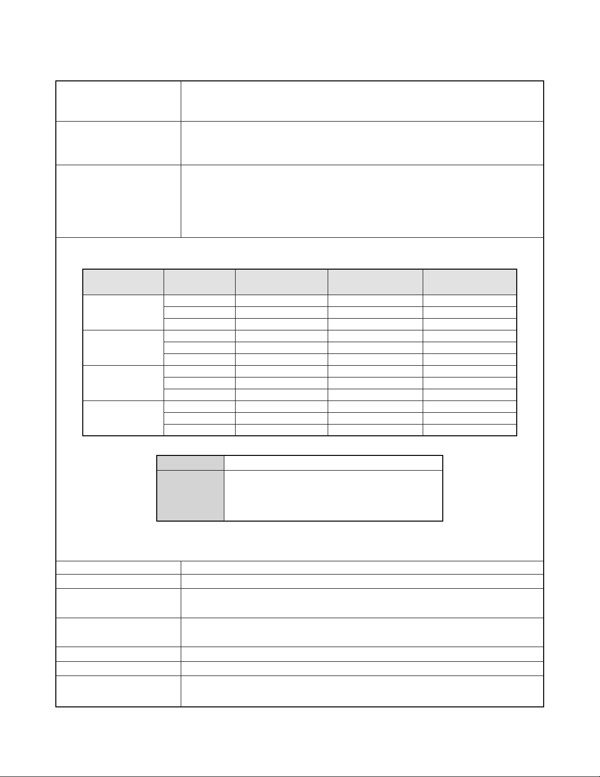
SPECIFICATIONS
Image Files Format Snapshots: JPEG (Exif Ver.2.2); DCF (Design rule for Camera File system) 1.0 standard; DPOF
compliant
Movies: AVI (Motion JPEG)
Recording Media 10MB built-in Flash memory
SD Memory Card
Multimedia Card
Image Size Snapshots: 2048 x 1536 pixels
1600 x 1200 pixels
1280 x 960 pixels
640 x 480 pixels
Movies: 320 x 240 pixels
Approximate Memory Capacity and File sizes
• Snapshots
File Size
(pixels)
2048 x 1536
1600 x 1200
(UXGA)
1280 x 960
(SXGA)
640 x 480
(VGA)
• Movies (320 x 240 pixels)
* Based on Matsushita Electric Industrial Co., Ltd. products. Capacity depends on card manufacturer.
* To determine the number of images that can be stored on a memory card of a different capacity, multiply the capacities in
the table by the appropriate value.
Delete Single-file, all files (with protection)
Effective Pixels 3.20 million
Imaging Element 1/1.8-inch square pixel color CCD
Lens/Focal Distance F4.2; f=7.1mm
Zoom 4X digital zoom
Focusing Fixed focal point
Approximate Focus Range
(from lens surface) 1m to ∞ (3.3´ to ∞)
Quality
Fine
Normal
Economy
Fine
Normal
Economy
Fine
Normal
Economy
Fine
Normal
Economy
Data Size
Recording Time
(Total pixels: 3.35 million)
(equivalent to approximately 35 for 35mm film)
One Movie: 30 seconds maximum
Total Movie Time:
80 seconds maximum (built-in memory)
500 seconds maximum (SD 64 MB memory card)*
Approximate
Image File Size
1.6MB
1.2MB
630KB
1050KB
710KB
370KB
680KB
460KB
250KB
190KB
140KB
90KB
130 KB/second max.
Built-in flash
memory 10MB
5 shots
7 shots
14 shots
8 shots
12 shots
24 shots
13 shots
20 shots
35 shots
46 shots
61 shots
98 shots
SD Memory
Card*64MB
34 shots
45 shots
88 shots
53 shots
79 shots
154 shots
82 shots
126 shots
221 shots
294 shots
386 shots
618 shots
— 1 —
Page 4
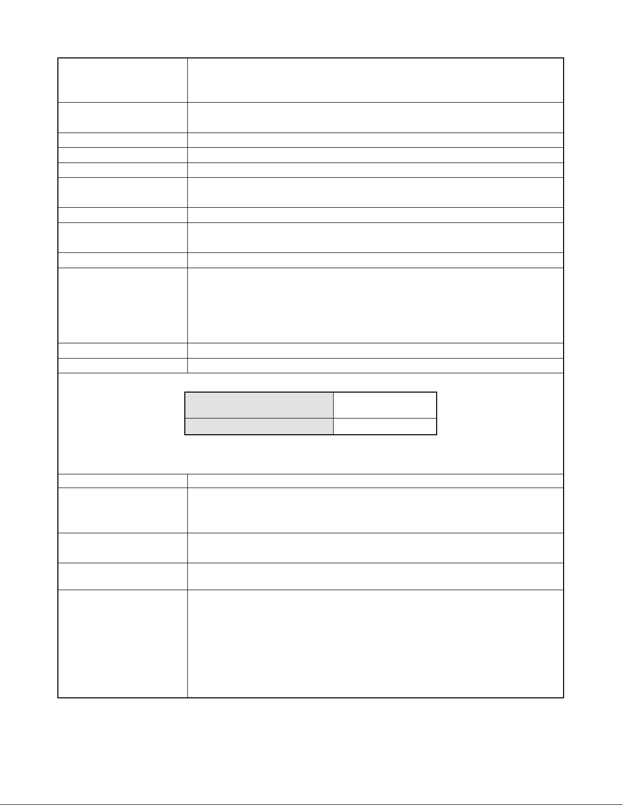
Exposure Control Light Metering: Multi-pattern by CCD
Exposure: Program AE
Exposure Compensation: –2EV to +2EV (1/3EV units)
Shutter CCD electronic shutter; mechanical shutter, 1 to 1/6400 second
(Depends on REC mode and ISO sensitivity setting being used.)
Aperture F4.2/fixed
White Balance Automatic, fixed (4 modes), manual switching
Self-timer 10 seconds, 2 seconds, Triple Self-timer
Built-in Flash Flash Modes: AUTO, ON, OFF, Red eye reduction
Flash Range: 1 to 2 meters (3.3' to 6.6') (ISO Sensitivity: “Auto”)
Recording Functions Snapshot; Best Shot; Movie
Monitor Screen 2.0-inch TFT color LCD
84,960 pixels (354 x 240)
Viewfinder Monitor screen and optical viewfinder
Timekeeping Functions Built-in digital quartz clock
Date and Time: Recorded with image data
Auto Calendar: To 2049
World Time: City; Date; Time; Summer time;
162 cities in 32 time zones
Input/Output Terminals Cradle connector
Power Supply Power Requirements: Rechargeable lithium ion battery (NP-20) x 1
Approximate Battery Life:
Continuous Recording
(Continuous Snapshot Recording)
Continuous Playback
80 minutes (480 shots)
120 minutes
The values noted above are approximate values until power fails at normal temperature (25°C (77°F)). The above does
not guarantee that you will be able to achieve this level of operation. Low temperatures shorten battery life.
Power Consumption DC 3.7V Approximately 3.5W
Dimensions 89.5(W) x 57(H) x 11.7(D) mm
(3.5˝(W) x 2.2˝(H) x 0.5˝(D))
(excluding projections)
Weight Approximately 72 g (2.5 oz)
(excluding battery and accessories)
Bundled Accessories Rechargeable lithium ion battery (NP-20); USB cradle (CA-22); Special AC adaptor; USB cable;
Dummy Card; Strap; CD-ROM; Basic Reference
Rechargeable Lithium Rated Voltage: 3.7 V
Ion Battery (NP-20) Rated Capacitance: 680 mAh
Operating Temperature
Range: 0°C to 40°C (32°F to 104°F)
Dimensions: 33 (W) x 50 (H) x 4.7 (D) mm
(1.3˝ (W) x 2.0˝ (H) x 0.19˝ (D))
Weight: Approximately 16 g (0.56 oz)
— 2 —
Page 5

USB Cradle (CA-22) Input/Output Terminals Camera connector; USB port; AC adaptor terminal (DC IN 5.3V)
Power Consumption DC 5.3V Approximately 3.4W
Dimensions 109(W) x 38.5(H) x 57(D) mm
(4.3˝(W) x 1.5˝(H) x 2.2˝(D))
(excluding projections)
Weight Approximately 61 g (2.1 oz)
Special AC Adaptor Power Requirement 100 to 240V AC, 50/60Hz, 0.12A
(Inlet Type) Output 5.3V DC, 1.0A
Dimensions 48(W) x 28(H) x 66(D) mm
(1.9"(W) x 1.1"(H) x 2.6"(D))
(excluding projections and cable)
Weight Approximately 120 g (4.2 oz)
Special AC Adaptor Power Requirement 100 to 240V AC, 50/60Hz, 0.12A
(Plug-in Type) Output 5.3V DC, 1.0A
Dimensions 47(W) x 20(H) x 72(D) mm
(1.9"(W) x 0.8"(H) x 2.8"(D))
(excluding projections and cable)
Weight Approximately 110 g (3.9 oz)
Power Supply
• Use only the special NP-20 rechargeable lithium ion battery to power this camera. Use of any other type of battery is not
supported.
• This camera does not have a separate battery for the clock. The date and time settings of the camera are cleared whenever
power is totally cut off (from both the battery and USB cradle). Be sure to reconfigure these settings after power is interrupted.
LCD Panel
• The LCD panel is a product of the latest LCD manufacturing technology that provides a pixel yield of 99.99%. This means that
less than 0.01% of the total pixels are defective (they do not turn on or always remain turned on).
Options
Mobile charger (with AC adaptor) BC-10L
Cradle (with AC adaptor) CA-22
Soft case ESC-30
ESC-31
Neck strap ENS-1
* Refer to the sales section for the details of the options.
— 3 —
Page 6
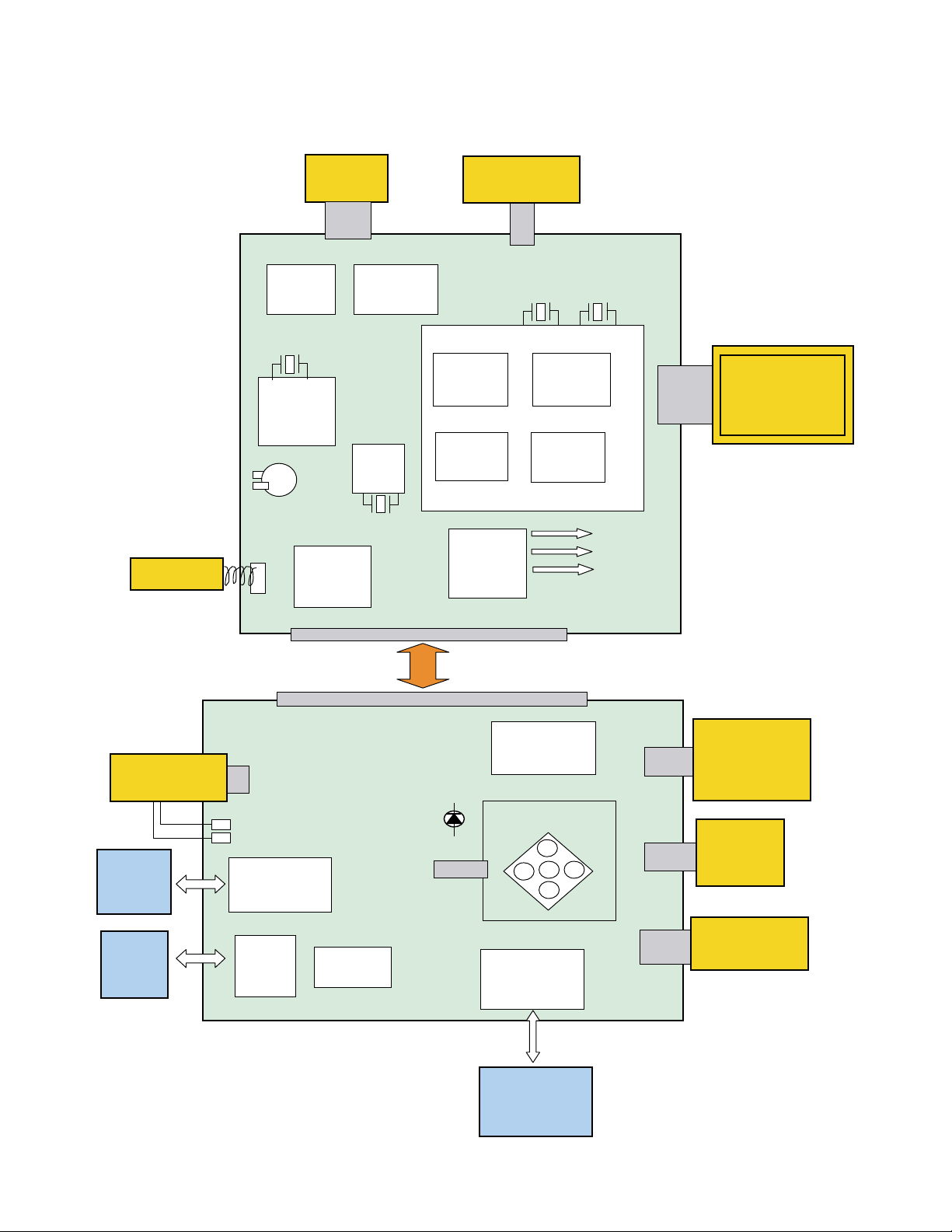
BLOCK DIAGRAM
SUB-PCB
Main-PCB
Microphone
Main-PCB
CDS/AD
AD80069
8bit micom
M37516
back up
ca
pacitor
ADC/Sound
3M CCD-
Lenz
module
Amp
AK4536
V-Driver
CXD3440EN
RTC
R2051
Lenz barrier/
Mechanical shutter/
IRF•LPF unit
SH-micom
HJ931601LP ( Stack MCM )
64M
SDRAM
Power
supply block
16M Flash
Memory
HG76C
2.0 inch TFT
COD2053AD
Vcc1.5
Vcc3.3
Vcc15
VEE7.5
Vcc5
EVCC3.3
Strobe Unit
SD/MMC
Card
NP-20
Li-ion
Battery
SUB-PCB
Storobe Vcc
SD Card
Connecter
Battery
spring
Fuse 1.25A
60pin Board to Board connecter
MENU/DISP/
MODE SW
LED
KEY PCB
16pin Cradle
Connecter
USB Cradle
LED Back Light
Unit
Buzzer
Power + Shutter
Key unit
— 4 —
Page 7
TEST MODE
Note: Do not perform the menu item unless explained here. (It may damage the internal data and
camera becomes unusable.)
Booting
To boot the test mode
While firmly pressing down both "MENU" and "DISP" buttons, Turn the power on.
2 "POWER" button
1 "MENU" + "DISP"button
++ KX856 ++
PR : 03.02.28.09.12
LD : 2.00
MI : 94
"Right" button -> "Right" button "MENU" button
1 :VERSION INFO
2 :VIDEO OUT
3 :USB TCC TEST
4 :TEST MENU
5 :BEEP TEST
6 :TASK-2 TEST
7 :ROM UPDATE
8 :ADJ TEST
9 :REC-INFO
10 :TEST SCRIPT
11 :LAST MEMORY
"SET" button
"MENU" button
"Right" button
1 :KEY CHECK
2 :VOCM CHECK
3 :MEMORY CHECK
4 :COLOR CHECK
5 :UGAIN CHECK
6 :VGAIN CHECK
7 :MESSAGE CHECK
8 :LED CHECK
9 :SW&JACK CHECK
10:MIC CHECK
— 5 —
Page 8

PROGRAM VERSION UPGRADING
■ Introduction
Update the program using an SD card.
Note:
Make sure to use a fully charged battery.
MAIN PCB becomes unusable if power down or an error occurs during program transmission.
1. How to confirm the program version
■ The program version can be confirmed in the test menu (refer to the previous page).
■ Turn the power on while pressing MENU button.
The following program version can be found.
Check the LCD display.
(Example)
VER 1.00
(As of March 14. 2003)
2. How to update the firmware
1. Prepare the memory card which contains the software for upgrading EX-S3 firmware in the root directory .
firmware: EX-S3.bin
The firmware is included in the service CD-ROM.
The location is as follows: QV/Soft/Adj-soft/Exs3/FirmUP
2. Insert the above memory card in the camera and then set a fully charged battery in the camera.
3. While pressing MENU, press power switch. Keep pressing MENU until “PROGRAM UPDATE” appears
in the camera LCD.
• The following appears.
• The version for the firmware update software in the memory card appears at the bottom.
PROGRAM UPDATE
YES
NO
NEW VERSION IS
VER 1.00
Note:
This does not appear when the battery is low.
Make sure to charge the battery fully.
4. Align the white cursor to “YES” by the cross key of 왖 and 왔, and press SET of the center of the cross
key.
• “NOW LOADING” appears in the LCD and the update starts.
5. “COMPLETE” appears after the update finishes.
— 6 —
Page 9

6. Remove the memory card after turning the power off once. T urn the power back on again while pressing
MENU, and check the version.
VER 1.00
(As of March. 2003)
7. If the version is correct, turn the power off.
8. Finally, check the operation by recording, playing back and deleting an image.
3. How to restore the firmware
1. Prepare the following firmware restoration program and change its name as follows;
kx856r030228.hbn 앶앸 mercury.bin
The program is included in the service CD-ROM.
Location: QV/Soft/Adj-soft/Exs3/Recover
2. Copy the above file to the root directory in the memory card.
3. Insert the memory card into the camera.
4. Set a fully charged battery in the camera.
5. Turn the power on while pressing the shutter release button.
The LED next to the LCD monitor changes from orange blinks 앶앸 green blinks 앶앸 green lights.
6. When the green LED lights, the firmware restoration is finished.
Remove the battery.
7. Turn the power on again while pressing MENU and DISP buttons.
The firmware is successfully restored if the following version appears.
PR:03.02.28.09.12
8. Finally, start the camera normally to check the operation by recording, playing back and deleting an
image.
— 7 —
Page 10

COLOR ADJUSTMENT
■ Introduction
Make sure to perform the adjustment when replacing the lens unit or the MAIN PCB.
The necessary software, driver and setting are explained in using USB ADJ Tool "adj856.exe".
Note that the tool, drivers etc. are available only for Windows.
1. How to use USB ADJ Tool
1-1. Prepare the necessary software, driver and DLL file.
(1) Prepare the following three files.
• Commom test driver for CASIO/PENTAX
[testmode_pentax_casio] folder uusbd.dll
uusbd.inf
uusbd.sys
• ADJ data read/write tool "adj856.exe"
• Commom DLL for USB test "uusbd.dll"
(2) Place the commom test driver for CASIO/PENTAX in an appropriate place.
(3) After downloading the common DLL for USB test, copy it to the same directory as that of the ADJ data
read/write tool or under "c:windows/system.
1-2. Set the camera so that it recognizes the USB test mode.
(1) Enter the test mode and then the initial test selection screen.
Turn the power on while pressing both "MENU" and "DISP".
Press "RIGHT", "RIGHT" and "MENU.
(2) Move the cursor to "3:USB TCC TEST" and press "SET".
(3) Move the cursor to "1:USB TCC ON" and press "SET".
(4) Press "MENU" button and leave the test mode.
(5) This enables the camera to recognise the USB test mode flag.
(6) When the USB test mode flag is ON, the test menu appears first when the camera power is turned on.
* If the USB test mode flag should be OFF, set "2: USB TCC OFF" in the test menu.
1-3. Install the USB driver for the USB test mode in the computer.
(The following is an example using the Windows Me.)
(1) Prepare the USB driver for the USB test mode.
(2) Turn the camera power on which is set in the USB test mode and let it enter the USB test mode as
shown in 1-2.(the test menu appears right after the power is turned on).
(3) Connect the camera in the above status to the computer by the USB cable.
(4) "A wizard for the new hardware" appears.
(5) Check "Designate the place for the driver (for users with sufficient knowledge)" and press "Next".
(6) Check "Search for the optimum driver for the device (recommended)".
(7) Check "Designate the place to search" , designate the place which contains "inf" file in the driver by
pressing "Reference" button, and then press "Next" button.
(8) When "Universal USB Driver (VMEM manufacturer's name)" appears upon message "Searching for
the driver file for the following devices" , press "Next" button.
(9) The file copy starts.
(If a message "uusbd.Inf cannot be found" appears during the file copy, designate the same place as in
the step 7).
(10) Press "Complete" button.
(11) Right-click "My computer", select "Property" and open "Device manager". If "Universal USB Driver
(VMEM manufacturer's name)" can be found in "USB device for UUSBD", the computer has successfully
recognised the driver.
(12) The test driver can be used for both CASIO/PENTAX. Installing the test driver into either one enables
the other one to recognise it.
— 8 —
Page 11

NOTE: How to uninstall the USB driver for the USB test mode
• Connect the camera while in the USB test mode to the computer so that the computer recognises the
camera.
• Right-click "My computer", select "Property" and open "Device manager".
• Select "USB device for UUSBD" , and then "Universal USB Driver (VMEM manufacturer's name)".
• Press "Delete" button and delete the driver.
• When using Windows98/98SE/Me, delete the following three files;
(NOTE! Do NOT delete "usbd. inf" and "usbd.sys", whose names are much alike the following.)
C:windows / inf / uusbd.inf
C:windows / inf / other / KashiwanoUUSBD.inf
C:windows / system32 / drivers / uusbd.sys
• The driver has been successfully deleted.
1-4. Use the USB ADJ Tool
(1) Prepare ADJ data read/write tool "adj856.exe".
(2) Copy the common DLL for USB test to the same directory as that of the ADJ data read/write tool
"adj856.exe" or under "c:windows / system".
(3) Turn the camera power on which is set in the USB test mode and let it enter the USB test mode (the test
menu appears right after the power is turned on).
Connect the camera to the computer by the USB cable.
(4) Boot "adj856.exe" and use it as follows;
• Read ADJ data from the camera. Press "read from the camera".
• Write ADJ data into the camera. Press "write into the camera".
• Save ADJ data which is read. Press "File" and "Save", and save it with an appropriate name.
• Open ADJ data which is saved. Press "File" and "Open", and open the necessary file.
— 9 —
Page 12

2. Lens Replacement
Make sure to perform the following procedure after replacing the lens.
A floppy disk with the lens data is bundled in the spare parts of the lens unit.
1 Enter the TEST mode.
1.Turn the power on while pressing both "MENU" and "DISP" buttons.
2.Press "RIGHT" button, "RIGHT" button and "MENU" button while
the program version is displayed.
3.Select "3.USB TCC TEST", and press "SET" button.
4.Select "1. USB TCC ON", and press "SET" button.
5.Turn the power OFF.
2 Set the camera to the cradle and turn the power on and connect it to the
computer by the USB cable.
3 Boot "adj856.exe" .
4 Click "ADJ ALL READ", and display the data on the "adj856.exe".
5 Find the No.430, "V-COM DC".
6 Write down this value(data).
7 Replace the Lens unit.
8 Perform the above 1 to 3
9 From "File/Open", open the bundled floppy disk, and transfer the data to
the "adj856e.exe".
0 Find the No.430,"V-COM DC"
A Change the data to the former value.(Refer to 6).
B Click "WRITE" button of "ADJ ALL".
C After adjustment, change "1. USB TCC ON" to "2. USB TCC OFF".
5
9
3. MAIN PCB Replacement
Make sure to backup ADJ DATA before replacing the MAIN PCB.
Firmware is not installed in spare parts.
1 Enter the TEST mode.
1. Turn the power on while pressing both "MENU" and "DISP" buttons.
2. Press "RIGHT" button, "RIGHT" button and "MENU" button while the program version is displayed.
3. Select "3.USB TCC TEST", and press "SET" button.
4. Select "1. USB TCC ON", and press "SET" button.
5. Turn the power OFF.
2 Set the camera to the cradle and turn the power on and connect it to the PC by the USB cable.
3 Boot "adj856.exe" .
B
— 10 —
Page 13

4 Click "ADJ ALL READ", and display the data on the "adj856.exe".
5 Save the data.
6 Replace the MAIN PCB.
7 Writing the Firmware
Write the firmware into a spare part after replacing one.
NOTE: If a battery is inserted without the firmware, only LED lights
green and the camera does not operate.
There may be a case in which spare parts with the firmware
already installed are provided.
In such case, it is not necessary to write the firmware.
1. Write the firmware
a)
Copy the following restoration software and the firmware to a SD card.
Restoration software: kx856r030228.hbn
Firmware: EX-S3.bin
b) Copy both the restoration software and the firmware into the root
directory of the SD card.
c) Change the name of the restoration software to "mercury.bin".
d) Insert the SD card.
e) While pressing the shutter key, insert a fully charged battery.
f)
The LED changes from "orange blinks" 씮 "green blinks" 씮 "green lights".
g) After the LED lights green, the firmware is written.
h) Remove the battery.
2. Initialize the system
a) Enter the TEST mode.
b) Select "7:ROM UPDATE" and press SET button.
c) Next, select "5:SYSTEM INITIAL" and press SET button.
d) The following message appears.
SYSTEM INITIALIZE
START
...
PUSH OK KEY?
e) Press SET button and System is initialized.
But the message, "SYSTEM ERROR", still appears on the monitor.
3. Write firmware again
Refer to the "How to update the firmware" on page 6.
Write the firmware.
If the TEST mode boots automatically, change "USB TCC ON" to
"USB TCC OFF".
8 Perform the above 1 to 3.
9 Open the file which is saved above, and display the data on the
"adj856.exe".
0 Click "WRITE" button of "ADJ ALL".
A After adjustment, change "1. USB TCC ON" to "2. USB TCC OFF".
5
4
9
0
4. Current consumption
(1) Current consumption (DC in = 3.70 ~ 4.05 [V])
• Make sure that current consumption is less than 330 mA in PLAY mode.
• Make sure that current consumption is less than 460 mA in REC mode.
• Make sure that current consumption is less than 4 mA when power is turned OFF.
(2) The battery indicator changes according to the voltages as follows.
• DC in = less than 3.74 ± 0.02V: (PLAY mode)
• DC in = less than 3.66 ± 0.02V: (PLAY mode)
• DC in = less than 3.44 ± 0.02V: (PLAY mode)
— 11 —
Page 14

VCOM DC ADJUSTMENT
■ Purpose
Readjust the VCOM value to minimize the flicker of the LCD after replacing the LCD or the main PCB.
■ Necessary tools
1. Camera (Charge its battery fully)
2. Photo diode (S2281-01) : See Fig 1.
3. Photo sensor amp (C2719) : See Fig 2.
4. BNC-BNC cable (E2573) x 2 : See Fig 3.
5. 9-volt alkaline battery (6LR61Y) x 2 : See Fig 4.
6. Oscilloscope
■ Preparation
1. The three tools can be obtained from the following global site.
Photo diode (S2281-01)
Photo sensor amp (C2719)
BNC-BNC cable (E2573)
www.hamamatsu.com/
2. 9-volt alkaline battery is a standard one, but can be obtained from the following global site as well.
www.panasonic.co.jp/global/
Fig1 Photo Diode (S2281-01) Fig2 Photo Sensor Amp (C2719)
Fig3 BNC-BNC Cable (E2573) Fig4 6LR61Y
— 12 —
Page 15

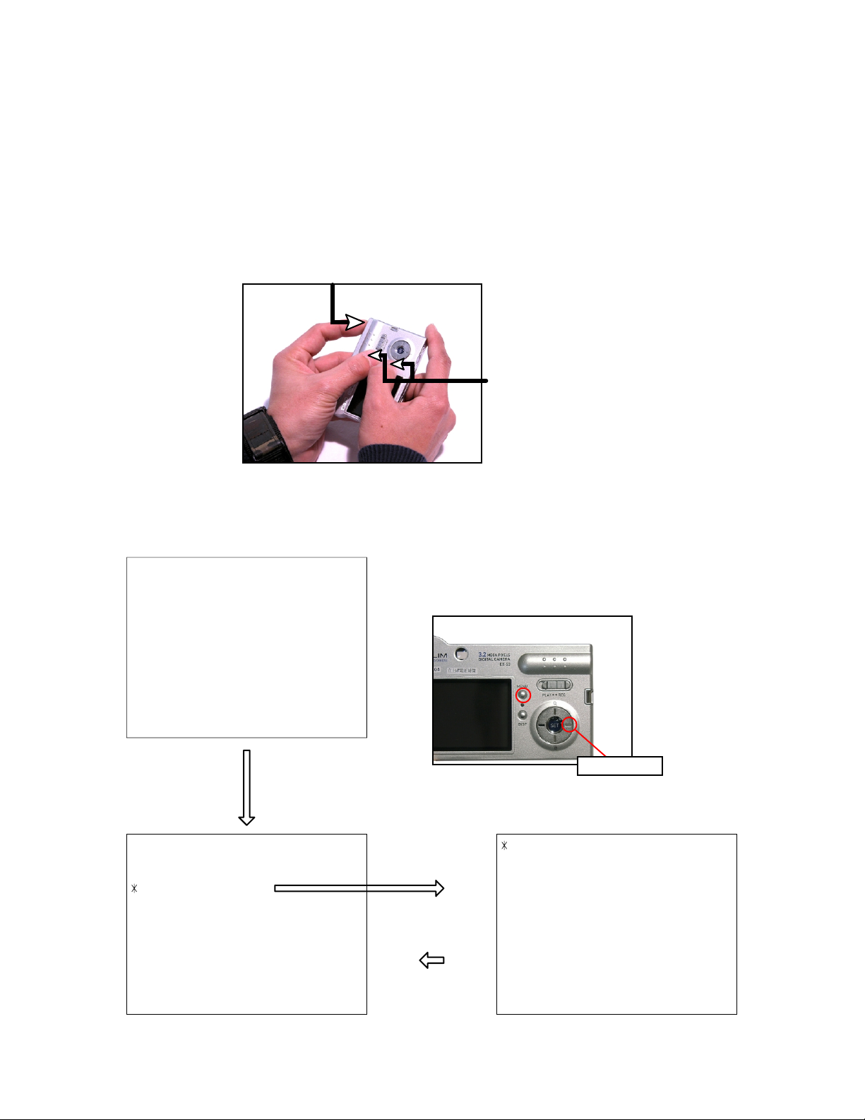
■ Procedure
1. Camera setting
a) Turn the power on while pressing MENU and DISP.
After pressing “Right” key twice, press MENU.
Figure (a) appears.
b) Select “8 : ADJ_TEST” and then press SET.
(See Figure (b).)
c) Next, select “1. VCOM” and then press SET.
(See Figure (c).)
Figure (a)
1 :VERSION INFO
2 :VIDEO OUT
3 :USB TCC TEST
4 :TEST MENU
5 :BEEP TEST
6 :TASK-2 TEST
7 :ROM UPDATE
8 :ADJ TEST
9 :REC-INFO
10 :TEST SCRIPT
11 :LAST MEMOR
Figure (b)
1:VCOM 7f
2:SHUT
3:AWB
.
.
.
Figure (c)
VCOM ADJ START?
<<START>>
PUSH OK KEY?
<<STOP>>
PUSH PW KEY?
Y
Figure (d)
d) Pressing SET causes the right figure to appear.
(See Figure (d).)
This value is an example and differs by products.
OK -> Register Write
VCOM = 0x7f
2. Connecting the TOOL
a) Place two 9-volt alkaline batteries in C2719.
b)
Connect the output terminal of C2719 to the channel terminal of the oscilloscope by the BNC-BNC cable.
c) Connect the input terminal to the Photo Diode by the BNC cable.
d) Turn the oscilloscope and C2719 on.
* Pull the ON/OFF switch of C2719 this way and raise/lower it. (See below Figure.)
— 13 —
Page 16

3. Measurement
a) Connect S2281-01 to the camera’s LCD monitor (see below).
AC Waveforms appear on the monitor screen of the oscilloscope.
* Change the Rf range of C2719 in case the range does not match.
Photo diode
S2281-01
INPUT OUTPUT
Oscilloscope
Photo sensor amp
CAMERA
BNC-BNC cable
LCD
Minimize the
ripple components
b) After AC waveforms of the oscilloscope appear , minimize it by pressing the camera’s up/down buttons
(see the picture).
Make sure to visually check if it has been minimized.
"Up" button
After it has been minimized, press SET key.
The screen in the right figure appears and the new VCOM
is written (VCOM adjustment is finished.).
This value is only an example, and differs by products.
Return to the previous display by pressing MENU or PW key.
"Down" button
OK -> Register Write
VCOM = 0X80
LAST MEMORY SET!
— 14 —
Page 17

THE COUNTERMEASURE FOR "SYSTEM ERROR"
■ Purpose
System error may occur when the battery is removed while data is written to the internal memory.
If "SYSTEM ERROR" appears on the monitor, execute the following operation.
1. Back up the ADJ DATA.
2. Initialize the system.
3. Write the firmware.
4. Initialize the system again in order to initialize ADJ DATA.
5. Write the firmware again.
6. Return the backed up ADJ DATA.
7. Check the operation in the test mode.
■ PROCEDURE
1. Back up the ADJ DATA(Refer to the page 10 to 11).
a) Enter the TEST mode.
Turn the power on while pressing both "MENU"and "DISP" buttons.
Press "RIGHT" button, "RIGHT" button and "MENU" button.
b) Select "3.USB TCC TEST", and press "SET" button.
c) Select "1.USB TCC ON", and press "SET" button.
d) Turn the power OFF.
e) Set the camera to the cradle and turn the power on and connect it to the PC by the USB cable.
f )Boot "adj856.exe".
g) Click "ADJ ALL READ", and display the data on the "adj856.exe".
h) Save the ADJ data.
Proceed to the next operation even if ADJ DATA cannot be saved.
2. Initialize the system.
a) Enter the TEST mode.
b) Select "7:ROM UPDATE" and press SET button.
c) Next, select "5:SYSTEM INITIAL" and press SET button.
d) The following message appears.
SYSTEM INITIALIZE
START
PUSH OK KEY?
e) Press SET button and System is initialized.
But the message, "SYSTEM ERROR", still appears on the monitor.
3. Write firmware.
Refer to the "How to update the firmware" on page 6.
Write the firmware.
If the TEST mode boots automatically, change "USB TCC ON" to "USB TCC OFF".
4. Initialize the system again.
Operation is the same as 2.
Proceed to the next operation even if "SYSTEM ERROR" appears on the monitor.
5. Write the firmware again.
Operation is the same as 3.
...
— 15 —
Page 18

6. Return the backed up ADJ DATA.
a) Select "USB TCC ON".
b) Set the camera to the cradle and turn the power on and connect it to the PC by the USB cable.
c) Boot "adj856.exe".
d) Open the file which is saved above and display the data on the "adj856.exe".
e) Click "WRITE" button of "ADJ ALL".
7. Operation check
Boot TEST MODE.
Select "8:ADJ TEST" and press SET button.
a) When ADJ DATA can be backed up;
If both "3:AWB" and "6:KIZU" are OK, adjustment is completed.
In case "3:AWB" or "6:KIZU" is not OK, repeat the operation 2 and 3.
b) When ADJ DATA can not be backed up;
"AWB" and "KIZU" are "????".
Check the images in the REC mode and Play mode.
Adjustment is completed if the camera works properly.
After check, boot TEST mode again.
Select "3.USB TCC TEST", and press "SET" button.
Select "2.USB TCC OFF", and press "SET" button.
Replace the Main PCB if the camera does not recover.
— 16 —
Page 19

1. Remove the battery.
2. Remove the four screws.
DISASSEMBLY
screws
screw
3. Remove the rear case ASS’Y.
screw
— 17 —
Page 20

4. Remove the FPC.
5. Remove the switch unit.
FPC
6. Remove two connectors.
8. Remove the LCD unit.
connectors
7. Remove the FPC.
FPC (When assembling, make sure to fix it tightly.)
Lead wire (black)
Lead wire (red)
9. Remove the FPC and then unsolder the
two lead wires.
FPC
10. Remove the sub PCB from the main PCB.
Lead wire
* When assembling, make sure to fix the sub PCB to
the main PCB tightly.
— 18 —
Page 21

11. Remove the hook.
12. Remove the strobe unit (including the condenser).
hook
13. Remove the two FPCs. 14. Remove the lens unit.
FPCs
15. Remove the main PCB.
— 19 —
Page 22

EXPLODED VIEW
3
20
1
4
6
7
11
10
12
10
2
8
S1
9
13
5
15
S1
14
17
16
S1
18
19
— 20 —
Page 23

N Item Parts Code Parts Name Specification QTY Price R Remark
PARTS PRICE LIST
Code
N 1 10115554 PCB ASSY / SUB RJK504515*001 TK 1 CT B
N 2 10115553 PCB ASSY / MAIN RJK504514*001 TK 1 DY A
N 3 10114781 STROBE UNIT XEST-K856 1 CC C
N 4 10115587 LENS UNIT RJK504532*001 TK 1 DY B *1
N 5 10113551 BS UNIT AQV-1401 1 CB C
N 6 10113550 SW UNIT UBF013S01A 1 AZ C
N 7 10115552 ASSY / FRONT CASE RJK504510*001 TK 1 DH C
N 8 10113563 TAPE/ GRIP BASE RJK504403-001V01 1 AA X
N 9 10113561 GRIP BASE RJK504384-001V01 1 AG X
N 10 10113562 TAPE / GRIP A RJK504402-001V01 2 AA X
N 11 10113568 TAPE / GRIP B RJK504534-001V01 1 AA C
N 12 10113556 GRIP RJK504253-001V01 1 AH C
N 13 10115550 ASSY / REAR CASE RJK504504*001 TK 1 DF C
N 14 10115551 ASSY / BATTERY COVER RJK504507*001 TK 1 BE C
N 15 10113535 SW PLATE RJK504364-001V01 1 AA C
N 16 10113537 SW KNOB RJK504374-001V01 1 AF C
N 17 10113530 KEY / CURSOR RJK504211-001V01 1 AP C
N 18 10115586 DISPLAY ASSY RJK504518*001 TK 1 DM A
N 19 10113512 RATING PLATE A RJK504533-001V01 1 AA X US only
N 19 10113514 RATING PLATE C RJK504533-002V01 1 AA X
- S1 10081372 SCREW RJK502836-001V01 4 AA C
ACCESSORY
- 20 10113059 LITHIUM ION BATTERY MK11-2501 1 BW B
- - 10091600 DUMMY CARD / SD RJK503523-001V01 1 AB C
N - 10116182 CD-ROM CK856DCA01R 1 AH X
- - 10085898 USB CABLE UC-K851-CL10 1 AO C
- - 10006299 AC CORD CBL-K799-AC-JU 1 AO X *2
- - 10090406 AC CORD CBL-K851-AC-UK 1 BE X For UK
- - 10006300 AC CORD CBL-K799-AC-EU 1 AR X For Euro
- - 10085887 AC ADAPTOR AD-C50J-WW 1 BR B *3
- - 10085906 AC ADAPTOR AD-C50G-WW 1 BT B
N - 10116181 CRADLE WAU0990-002AL 1 CM B
- - 10085897 STRAP ST-K851-A 1 AE C
N : New parts
*1 : Floppy disk is attached in the spare part.
*2 : For Blade(US) type.
*3 : For US, AC CORD is built-in.
- 21 -
Page 24

PRINTED CIRCUIT BOARDS
MAIN PCB
— 22 —
Page 25

SUB PCB
— 23 —
Page 26

MAIN PCB (1/2)
SCHEMATIC DIAGRAMS
— 24 —
Page 27

MAIN PCB (2/2)
— 25 —
Page 28

SUB PCB
— 26 —
Page 29

CASIO TECHNO CO.,LTD.
Overseas Service Division
6-2, Hon-machi 1-Chome
Shibuya-ku, Tokyo 151-8543, Japan
 Loading...