

Page 1

EX-P700
INDEX
Ver. 2 Apr. 2005
SEP. 2004
(without price)
R
Page 2

CONTENTS
SPECIFICATIONS ....................................................................................................................................... 1
BLOCK DIAGRAM ...................................................................................................................................... 5
TEST MODE ................................................................................................................................................ 6
PROGRAM VERSION UPGRADING .......................................................................................................... 7
1. To update the firmware version ..................................................................................................... 7
2. How to restore the firmware........................................................................................................... 8
3. To install the firmware .................................................................................................................... 9
ADJ TOOL ................................................................................................................................................. 10
1. Preparation..................................................................................................................................... 10
2. How to use ADJ Tool when replacing Lens unit ........................................................................ 12
3. How to use ADJ Tool when replacing MAIN PCB ...................................................................... 13
VCOM DC ADJUSTMENT ........................................................................................................................ 14
CURRENT CONSUMPTION ..................................................................................................................... 17
THE COUNTERMEASURE FOR "SYSTEM ERROR" ............................................................................. 17
DISASSEMBLY ......................................................................................................................................... 18
EXPLODED VIEW ..................................................................................................................................... 28
PARTS LIST .............................................................................................................................................. 29
PRINTED CIRCUIT BOARDS ................................................................................................................... 30
SCHEMATIC DIAGRAMS ......................................................................................................................... 32
Page 3
SPECIFICATIONS
Image Files Format Snapshots: JPEG (Exif Ver.2.2); TIFF; DCF (Design rule for Camera File system) 1.0
standard; DPOF compliant
Movies: AVI (Motion JPEG)
Audio: WAV
Recording Media 8.9MB built-in flash memory
SD Memory Card
MultimediaCard
Image Size Snapshots: 3072 x 2304 pixels
3072 x 2048 (3:2) pixels
2304 x 1728 pixels
1600 x 1200 pixels
1280 x 960 pixels
640 x 480 pixels
Movies: 320 x 240 pixels
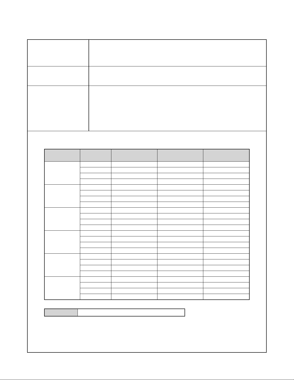
Approximate Memory Capacity and File sizes
• Snapshots
File Size
(pixels)
3072 x 2304
3072 x 2048
(3:2)
2304 x 1728
1600 x 1200
(UXGA)
1280 x 960
(SXGA)
640 x 480
(VGA)
Quality
Fine
Normal
Economy
TIFF
Fine
Normal
Economy
TIFF
Fine
Normal
Economy
TIFF
Fine
Normal
Economy
TIFF
Fine
Normal
Economy
TIFF
Fine
Normal
Economy
TIFF
Approximate Image
File Size
4.4MB
2.2MB
1.1MB
20.3MB
3.9MB
2.0MB
1.0MB
18.0MB
1.95MB
1.53MB
800KB
11.4MB
1.05MB
710KB
370KB
5.5MB
680KB
460KB
250KB
3.5MB
190KB
140KB
90KB
900KB
Built-in flash memory
8.9MB
2 shots
3 shots
7 shots
0 shot
2 shots
4 shots
8 shots
0 shot
4 shots
5 shots
10 shots
0 shot
7 shots
11 shots
22 shots
1 shot
12 shots
18 shots
32 shots
2 shots
42 shots
56 shots
90 shots
8 shots
SD Memory Card*
64MB
13 shots
26 shots
51 shots
2 shots
15 shots
29 shots
56 shots
2 shots
30 shots
37 shots
68 shots
4 shots
53 shots
79 shots
154 shots
9 shots
82 shots
126 shots
221 shots
14 shots
294 shots
386 shots
618 shots
55 shots
• Movies (320 x 240 pixels)
Data Size 300KB/second max.
* Based on Matsushita Electric Industrial Co., Ltd. products. Capacity depends on card manufacturer.
* To determine the number of images that can be stored on a memory card of a different capacity, multiply the capacities
in the table by the appropriate value.
— 1 —
Page 4

Delete Single-file, all files (with protection)
Effective Pixels 7.0 million
Imaging Element 1/1.8-inch square pixel color CCD (Total pixels: 7.47 million)
Lens/Focal Distance Eight lenses in seven groups, including an aspherical lens
F2.8 (W) to 4 (T); f=7.1 (W) to 28.4mm
(T) (equivalent to approximately 33 (W) to 132 (T) for 35mm film)
Zoom 4X optical zoom; 4X digital zoom
(16X in combination with optical zoom)
Focusing Combination phase differential sensor and contrast Auto Focus (AF) mode (AF Area: Spot,
Multi, or Free); Macro mode; Infinity mode; Manual Focus; focus lock
Approximate Focus Range Normal 40cm to ∞ (1.3´ to ∞)
(from lens surface) Macro Approximately 10cm to 50cm (3.9˝ to 19.7˝) at wide angle
Approximately 40cm to 50cm (15.6˝ to 19.7˝) at telephoto
Exposure Control Light Metering Multi-pattern by CCD
Exposure Program AE, Aperture priority AE, Shutter speed priority AE,
Manual exposure
Exposure Compensation –2EV to +2EV (1/3EV units)
Shutter CCD electronic shutter; mechanical shutter, Snapshot mode, BESTSHOT mode :
1/8 to 1/2000 second
Aperture Priority AE mode : 1 to 1/2000 second
Shutter Speed Priority AE mode, Manual Exposure mode : BULB, 60 to 1/2000 second
• Shutter speed is different for the following BESTSHOT scenes.
Night Scene: 4 to 1/2000 second
Fireworks: BULB, 60 to 1/2000 second
Aperture F2.8, 3.2, 3.5, 4.0, 4.5, 5.0, 5.6, 6.3, 7.1, 8.0
• Using optical zoom causes the aperture to change.
• An aperture setting from F2.8 to 5.6 is possible in the Snapshot mode
White Balance Automatic, fixed (7 modes), manual switching
Sensitivity Auto, ISO 80, ISO 160, ISO 320, ISO 640
Self-timer 10 seconds, 2 seconds, Triple Self-timer , Remote controller , Remote controller and 2-second
Self-timer
Built-in Flash Flash Modes AUTO, ON, OFF, Red eye reduction
Flash Range Wide Angle Optical Zoom: 0.4 to 3.6 meters (1.3´ to 11.8´)
Telephoto Optical Zoom: 0.4 to 2.5 meters (1.3´ to 8.2´)
(ISO Sensitivity: “Auto”)
Recording Functions Audio snapshot; Macro; self-timer; Aperture priority AE; Shutter speed priority AE; Manual
exposure;
BESTSHOT; Continuous shutter; Auto Bracketing; Movie with audio; voice recording
* Audio recording is monaural.
Audio Recording Time Audio Snapshot Approximately 30 seconds maximum per image
Voice Recording Approximately 38 minutes with built-in memory
After Recording Approximately 30 seconds maximum per image
Monitor Screen 2.0-inch TFT color LCD
115,200 pixels (480 x 240)
Viewfinder Monitor screen and optical viewfinder
Timekeeping Functions Built-in digital quartz clock
Date and Time Recorded with image data
Auto Calendar To 2049
World Time City; Date; Time; Summer time;
162 cities in 32 time zones
— 2 —
Page 5

Input/Output Terminals AC adaptor connector (DC IN); USB / AV port (Special mini port, NTSC/ PAL); External
flash sync terminal
Microphone Monaural
Speaker Monaural
Power Requirements
Power Requirements Rechargeable lithium ion battery
(NP-40) x 1
AC adaptor (AD-C40)
Approximate Battery Life:
The values below indicate the amount of time under the conditions defined below, until power automatically turns of f due to battery
failure. They do not guarantee that you will be able to achieve this level of operation. Low temperatures shorten battery life.
Operation
Number of Shots (CIPA Standard)*
1
(Operating Time)
Number of Shots, Continuous Recording*
2
(Operating Time)
Continuous Snapshot Playback*
Continuous Voice Recording*
3
4
Supported Battery: NP-40 (Rated Capacitance: 1230mAh)
Storage Medium: SD Memory Card
*1 Number of Shots (CIPA Standard)
• Temperature: 23°C (73°F)
• Monitor Screen: On
• Zoom operation between full wide to full telephoto every 30 seconds, during which two images are recorded, one image
with flash; power turned off and back on every time 10 images are recorded.
*2 Continuous Recording Conditions
• Temperature: 23°C (73°F)
• Monitor screen: On
• Flash: Off
• Image recorded every 10 seconds, alternating full wide-angle and full telephoto zoom
*3 Continuous Snapshot Playback Conditions
• Temperature: 23°C (73°F)
• Scroll one image about every 10 seconds
*4 Voice recording times are based on continuous recording.
Apporoximate Battery Life
200 shots
(100 minutes)
440 shots
(110 minutes)
220 minutes
210 minutes
Power Consumption 4.5V DC Approximately 5.5W
Dimensions 97.5(W) x 67.5(H) x 45.1(D) mm
(3.8˝(W) x 2.7˝(H) x 1.8˝(D))
(excluding projections; 26.1mm (1.0˝) at thinnest part)
Weight Approximately 225 g (7.9 oz) (excluding battery and accessories)
Bundled Accessories Rechargeable lithium ion battery (NP-40); Rapid charger (BC-30L); Card Remote Controller
(WR-4C); lithium battery (CR2025); AC power cord; USB cable; AV cable; Strap; CD-ROM;
Basic Reference
— 3 —
Page 6

Rechargeable Lithium Ion Battery (NP-40)
Rated Voltage 3.7 V
Rated Capacitance 1230 mAh
Operating Temperature
Range 0°C to 40°C (32°F to 104°F)
Dimensions 38.5(W) x 38.0(H) x 9.3(D) mm (1.5˝(W) x 1.5˝(H) x 0.37˝(D))
Weight Approximately 34 g (1.20 oz)
Rapid Charger (BC-30L) : Power Cord Type
Power Requirement 100 to 240V AC, 0.13A, 50/60Hz
Output 4.2V DC, 900 mA
Charging Temperature 5°C to 35°C (41°F to 95°F)
Chargeable Battery type Rechargeable lithium ion battery (NP-40)
Full Charge Times Approximately 2 hours
Dimensions 80 (W) x 55 (H) x 30 (D) mm (3.1˝(W) x 2.2˝(H) x 1.2˝(D)) (excluding projections)
Weight Approximately 60 g (2.1 oz)
Rapid Carger (BC-30L) : Plug-in Type
Power Requirement 100 to 240V AC, 0.13A, 50/60Hz
Output 4.2V DC, 900 mA
Charging Temperature 5°C to 35°C (41°F to 95°F)
Chargeable Battery type Rechargeable lithium ion battery (NP-40)
Full Charge Times Approximately 2 hours
Dimensions 80 (W) x 55 (H) x 25 (D) mm (3.1˝(W) x 2.2˝(H) x 0.98˝(D)) (excluding projections)
Weight Approximately 63 g (2.2 oz)
Card Remote Controller (WR-4C)
Power Requirements Lithium battery (CR2025) x 1
Approximate Battery Life 20,000 button operations
• One button operation is defined as depressing a button for one second, and then releasing
it for one second.
Operating Temperature 0°C to 40°C (32°F to 104°F)
Dimensions 35.0 (W) x 56.6 (H) x 6.5 (D) mm (1.38˝ (W) x 2.23˝ (H) x 0.26˝ (D))
Weight Approximately 11 g (0.39 oz) (including battery)
Power Supply
• Use only the special NP-40 rechargeable lithium ion battery to power this camera. Use of any other type of battery is not
supported.
• This camera does not have a separate battery for the clock. The date and time settings of the camera are cleared
whenever power is totally cut off (from both the battery and AC adaptor). Be sure to reconfigure these settings after
power is interrupted.
LCD Panel
• The LCD panel is a product of the latest LCD manufacturing technology that provides a pixel yield of 99.99%. This means
that less than 0.01% of the total pixels are defective (they do not turn on or always remain turned on).
Lens
• You may sometimes notice some distortion in certain types of images, such as a slight bend in lines that should be
straight. This is due to the characteristics of lens, and does not indicate malfunction of the camera.
— 4 —
Page 7
Conversion Lens Detection SW
UP
Converter
DOWN
Converter
TH
+
–
CCD-FPC
CCD
7M pix
1/1.8"
AD9949(QFN)
3.3V
CANON
Lens Unit
✕ 4
SONY (CXD3440WLCSP) 5 2
V.Driver
V.Driver
3.3V
15.0V
-7.5V
3.3V
1.8V
1.5V
SDRAM 256M
ASIC
S-AND FLASH
Motor Driver
LV8041FN
27MHz
SD
MAIN-PCB
10MHz
CODEC
AK4631
VCC3-SD
VIDEO
Amp
LA73072
USB/AV
out
(8pin)
DC in
Adapter
AD-C40
Li-ion Battery
1230mAh
(3.3V-4.2V)
SELF TIMER
KEY2-FPC
POWER
SHUTTER
WIDE
TELE
AE LOCK
SHIFT
CONT
UP, DOWN
RIGHT, LEFT
SET
MENU
DISP
TIMER
PREVIEW
MACRO
STROBE
MODE
DIAL
SW
(8-position)
KEY-UNIT
KEY1-FPC
R
BL LED ✕ 4
ICX489AQF
15.0V-7.5V
CDS
50pin
12pin
21pin
16pin
30pin
80pin
33pin
20pin
15V
AF-FPC
SW-PCB
R
G
48MHz
RTC
32KHz
VCC3-1
EVCC3.3V
REG
REG
3.3V
5.0V
3.3V
4.5V
VEE7.5
EVCC3.3
VCC1.5
VCC5
VCC1.8
VCC15
Phase Difference
Sensor
FM6270W45
MIC
Remote
Controler
SP
Stroboscope Synchrotron Terminal
Main
Capacitor
Charging
Booster
Trigger
ST-FPC
2.0" 11Mpix
Digital I/F LCD
VDC1:15.0V
VDD:3.0V
UP
Converter
DOWN
Converter
DOWN
Converter
8bit
Microprocessor
ML610501-014LA
BACK UP
Capacitor
inclination
sensor
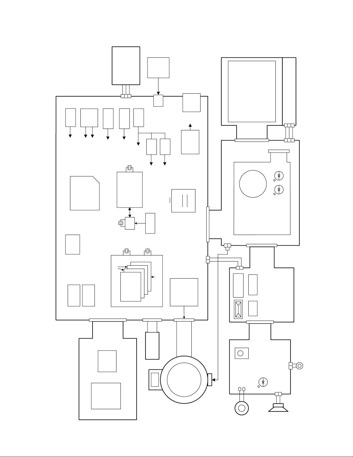
BLOCK DIAGRAM
— 5 —
Page 8
TEST MODE
Note: Never perform the menu items unless otherwise instructed. Doing so may cause destruction
of the data inside, which will make the camera unusable.
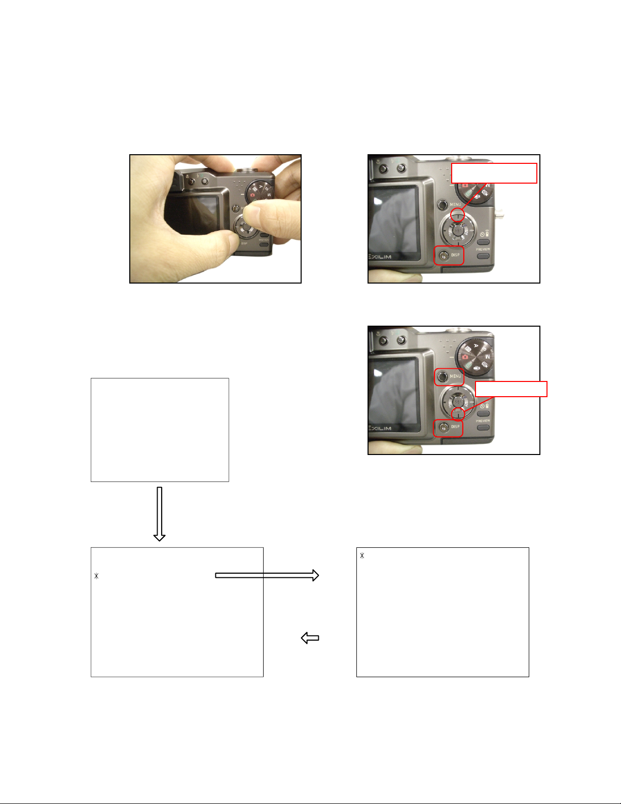
■ To boot the test mode
1. While firmly pressing down both [DISP] and [UPPER], turn the power on.
[UPPER] button
2. After the version appears, press buttons in the order of [DOWN], [DOWN], [DISP] and [MENU] in 0.5
second. The diagnostic menu appears.
Ver 1.00
++ KX824 ++
"DOWN" button -> "DOWN" button -> "DISP" button -> "MENU" button
1 :VERSION INFO
2 :VIDEO OUT
3 :USB TCC TEST
4 :TEST MENU
5 :SOUND TEST
6 :IMAGE FLAG
7 :ROM UPDATE
8 :ADJ TEST
9 :REC-INFO
10 :TEST SCRIPT
11 :LAST MEMORY
12 :FORMAT
"SET" button
"MENU" button
[DOWN] button
1 :USB TCC ON
2 :USB TCC OFF
3 :USB STORAGE
— 6 —
Page 9

PROGRAM VERSION UPGRADING
1. To update the firmware version
1. Prepare the memory card which contains the firmware for EX-P700 in the root directory.
EX-P700.bin
2. Insert the above memory card into the camera, and set a fully charged battery in the camera.
3. Press the [power button] while holding [MENU] depressed. Keep holding [MENU] depressed until
“PROGRAM UPDATE” appears in the display.
• The following appears.
• The version of the firmware in the memory card appears at the bottom of the display.
NOTE 1) When a wrong software is mistakenly used,
PROGRAM UPDATE
YES
NO
NEW VERSION IS
VER 1.00
(As of September 2004)
the message below appears. Update the
firmware again with the correct software.
FILE ERROR!
0x1002
NOTE 2) When only the version appears in the display
even though you are trying to operate the
camera, charge the battery to the fullest and
try again. The level of the battery indicator
should be highest in order to update the
firmware.
4. Align the white cursor to [YES] by [] and [], and then press [SET].
• “NOW LOADING” appears in the display and the update starts.
5. “COMPLETE” appears after the update finishes.
6. Remove the memory card after turning the power off once. Turn the power back on again while holding
[MENU] depressed, and check the version.
• “VER.1.00” appears.
VER 1.00
(As of September 2004)
7. If the version is correct, turn the power off.
8. Finally, check the operation by recording, playing back and deleting an image.
— 7 —
Page 10

2. How to restore the firmware
1. Prepare the firmware restoration program and change its name as follows;
“rom824_gm01.lbn” 씮 “jupiter.bin”
NOTE: This software and procedure automatically restores the firmware even if the firmware belongs
to a wrong model code. Make sure to use the correct software for the correct model.
2. Copy the above file to the root directory in the memory card.
3. Insert the memory card into the camera.
4. Set a fully charged battery in the camera.
NOTE: This software and procedure automatically restores the firmware even if the battery capacity of
the camera is low. Make sure to use a fully charged battery to prevent the danger of power
down during firmware restoration.
5. Turn the power on while pressing the [shutter release] button.
If the power does not turn on only by pressing the power button, insert the battery while holding the
[shutter release] button depressed.
• The LED next to the optical viewfinder changes from “green/red blinking”, “green blinking” to “green steady”.
NOTE: This software and procedure automatically restores the firmware even if the firmware belongs
to a wrong model code. Make sure to use the correct software for the correct mode.
6. When the LED becomes “green steady”, the firmware restoration is finished.
Remove the battery and the memory card, and then turn the power off.
7. Turn the power on again while holding [DISP] and [UPPER] depressed.
Check the model name and the program version (PR:) in the opening screen of the test menu.
++KX824++
Ver 1.00
8. If the model name and the program version are correct, perform SYSTEM INITIAL to initialize the
system area.
“DISP+ UPPER + PW ON” 씮 “DOWN, DOWN, DISP, MENU” 씮 “7:ROM UPDATE” 씮 “5:SYSTEM
INITIAL”
NOTE: After SYSTEM INITIAL is performed, “SYSTEM ERROR” appears when the power is turned
on again.
9. Write the latest firmware.
After the firmware is written, check the model name and the program version (PR:) in the opening
screen of the test menu.
10. Finally, start the camera normally to check the operation by recording, playing back and deleting an
image. Check also that the colors in the images are not too bright or two dark.
— 8 —
Page 11

3. To install the firmware
Initially, firmware is not installed in the PCB supplied by the parts center.
Install the firmware into the PCB after replacing with a new one as shown in the procedures below.
NOTE: The camera does not operate (only LED becomes “green blinking”) if the firmware is not installed
in the PCB.
<Writing the restoration program 1>
1. Copy the following software to the root directly of the SD card.
Restoration software: rom824_gm01.lbn
Firmware: EX-P700.bin
2. Change the name as follows;
“rom824_gm01.lbn” to “jupiter.bin”
3. Insert the SD card into the camera.
4. Insert the battery while holding the [shutter release] button depressed.
The LED next to the optical viewfinder changes from “green/red blinking”, “green blinking” to “green
steady”.
5. When the LED becomes “green steady”, remove the battery and turn the power off.
<System Initialize>
1. Boot the test mode.
2. Press [DOWN] twice and then press [DISP], [MENU].
3. Select “7: ROM UPDATE” and then press [SET].
4. Select “5: SYSTEM INITIALIZE” and then press [SET].
5. When the following message appears, press [SET].
SYSTEM INITIALIZE
START….
PUSH OK KEY?
6. The system initialize is executed. Turn off the power when “SUCCESS” appears.
* “SYSTEM ERROR” appears when the camera is turned off without system initialize.
<Writing the firmware>
1. Turn the power on while holding [MENU] depressed.
2. When “PROGRAM UPDATE” appears, select “YES” and then press [SET].
3. “NOW LOADING” appears while the firmware is updated.
4. When “COMPLETE” appears, the firmware update is complete.
5. Turn the power on and off to check if the camera normally functions. If there is no problem, the firmware
update is successful.
— 9 —
Page 12

ADJ TOOL
■ Introduction
Make sure to perform the adjustment by the USB ADJ Tool “adj03SSAW.exe” when replacing the lens
unit or the PCB.
Here the necessary software, driver and setting are explained to use “adj03SSAW.exe”.
Note that the tool, drivers etc. are available only for Windows.
1. Preparation
1-1. Prepare the necessary software, driver and DLL file.
1) Prepare the following three files.
• Common test driver for CASIO/PENTAX
[testmode_pentax_casio] folder uusbd.dll
uusbd.inf
uusbd.sys
• ADJ tool, USB DLL and ADJ setting file
[adj03SSAW] folder adj03SSAW.exe (ADJ tool itself)
uusbd.dll (USB DLL)
*.adt (ADJ setting file. Sorted by models)
* Place all files in the same folder.
2) Place the common test driver for CASIO/PENTAX in an appropriate place.
3) Place all of ADJ tool, USB DLL and ADJ setting file in the same folder.
1-2. Set the camera so that it recognizes the USB test mode.
1) Enter the test menu.
Turn the power on while pressing both [DISP] and [UPPER].
Press [DOWN], [DOWN], [DISP] and [MENU].
2) Move the cursor to “3: USB TCC TEST” and press [SET].
3) Move the cursor to “1: USB TCC ON” and press [SET].
4) The USB test mode flag is now saved in the camera. Turn the power off.
5) When the USB test mode flag is ON, the test menu appears first when the camera power is turned on.
* When turning the USB test mode flag OFF, set “2: USB TCC OFF” in the test menu.
1-3. Install the USB driver for the USB test mode in the computer.
(The following is an example using the Windows Me.)
1) Prepare the USB driver for the USB test mode.
2) Turn the camera power on which is set in the USB test mode as shown in 1-2 and let it enter the USB
test mode directly (the test menu appears right after the power is turned on).
3) Connect the camera in the above status to the computer by the USB cable.
4) The “Add new hardware” wizard appears.
5) Check “Designate the place for the driver (for users with sufficient knowledge)” and press “Next”.
6) Check “Search for the optimum driver for the device (recommended)”.
7) Check “Designate the place to search”, designate the place which contains “inf” file in the driver by
pressing “Reference” button, and then press “Next” button.
8) When “Universal USB Driver (VMEM manufacturer’s name)” appears upon message “Searching for
the driver file for the following devices”, press “Next” button.
— 10 —
Page 13

9) The file copy starts.
(If a message “uusbd.inf cannot be found” appears during the file copy, designate the same place as
in the step 7).
10) Press “Complete” button.
11) Right-click “My computer”, select “property”, and then open “Device manager”.
If “Universal USB Driver (VMEM manufacturer’s name)”,“USB device for UUSBD” can be found, the
computer has successfully recognized the driver.
12) The test driver can be used for both CASIO/PENTAX. Installing the test driver into either one enables
the other one to recognize it.
* How to uninstall the USB driver for the USB test mode
• Connect the camera to the computer while in the USB test mode so that the computer recognizes
the camera.
• Right-click “My computer”, select “Property” and open “Device manager”.
• Select “USB device for UUSBD” , and then “Universal USB Driver (VMEM manufacturer's name)”.
• Press “Delete” button to delete the driver.
• When using Windows98/98SE/Me, delete the following three files;
(NOTE! Do NOT delete “usbd.inf” and “usbd.sys”, whose names are much alike the following.)
C:windows / inf / uusbd.inf
C:windows / inf / other / KashiwanoUUSBD.inf
C:windows / system32 / drivers / uusbd.sys
• The driver has been successfully deleted.
1-4. Use the USB ADJ Tool
1) Prepare ADJ tool, USB DLL and ADJ setting file in the same folder.
2) Turn the camera power on which is set in the USB test mode and let it enter the USB test mode directly
(the test menu appears right after the power is turned on).
3) Boot “adj03SSAW.exe” and use it as follows;
• To read ADJ data from the camera
앶앸 Press “READ ($9)”.
There is no need to set the model by “FW Item Set”.
• To write ADJ data into the camera
앶앸 Press “WRITE ($8)”.
• To save ADJ data which is read
앶앸 Select “File” and “Save All ADJ”, and save it under an appropriate name.
• Open ADJ data which is saved
앶앸 1. Select the model by "FW Item Set", and then press "Load FW ->" button.
2. Select “File” and “Open”, and open the necessary file.
• Language” radio button can switch the language between Japanese and English in which the name
of the ADJ ITEM is displayed.
•“Radix” radio button can switch the data display between decimal and hexadecimal notations.
— 11 —
Page 14

2. How to use ADJ Tool when replacing Lens unit
Make sure to perform the following procedure after replacing the lens.
A floppy disk with the lens data is bundled in the spare parts of the lens unit.
1 Enter the TEST mode.
1. Turn the power on while pressing both "DISP" and "UP" buttons.
2. Press "DOWN" button, "DOWN" button, "DISP" button, and "MENU"
button while the program version is displayed.
3. Select "3.USB TCC TEST", and press "SET" button.
4. Select "1. USB TCC ON", and press "SET" button.
5. Turn the power OFF.
2 Connect the camera to the computer by the USB cable.
3 Boot "adj03ssaw" .
4 Select the model name and click "Load FW " Key.
• EX-P700 앶앸 Kx824
5 Click "ADJ ALL READ", and display the data on the "adj03ssaw".
6 Find the No.1163, "V-COM DC".
7 Write down this value(data).
8 Replace the Lens unit.
9 Perform the above 1 to 3.
6
4
0 Select the model name and click "Load FW " Key.
• EX-P700 앶앸 Kx824
A From "File/Open", open the bundled floppy disk, and transfer the data to
the "adj03ssaw".
B Find the No.1163,"V-COM DC"
C Change the data to the former value.(Refer to 7).
D Click "WRITE" button of "ADJ ALL".
E After adjustment, change "1. USB TCC ON" to "2. USB TCC OFF".
A
D
— 12 —
Page 15

3. How to use ADJ Tool when replacing MAIN PCB
Firmware is not installed in spare parts.
1 Enter the TEST mode.
1. Turn the power on while pressing both "DISP" and "UP" buttons.
2. Press "DOWN" button, "DOWN" button, "DISP" button and "MENU"
button while the program version is displayed.
3. Select "3.USB TCC TEST", and press "SET" button.
4. Select "1. USB TCC ON", and press "SET" button.
5. Turn the power OFF.
2 Connect the camera to the PC by the USB cable.
3 Boot "adj03ssaw".
4 Select the model name and click "Load FW " Key.
• EX-P700 앶앸 Kx824
5 Click "ADJ ALL READ", and display the data on the "adj03ssaw".
6 Save the data.
7 Replace the MAIN PCB.
8 Writing the Firmware.
Write the firmware into a spare part after replacing one.
NOTE: If a battery is inserted without the firmware, only LED blinks
green and the camera does not operate.
9 Perform the above 1 to 3.
0 Select the model name and click "Load FW " Key.
• EX-P700 앶앸 Kx824
A Open the file which is saved above, and display the data on the
"adj03ssaw".
B Click "WRITE" button of "ADJ ALL".
C After adjustment, change "1. USB TCC ON" to "2. USB TCC OFF".
6
5
4
A
B
— 13 —
Page 16

VCOM DC ADJUSTMENT
■ Purpose
Readjust the VCOM value to minimize the flicker of the LCD after replacing the LCD or the main PCB.
■ Necessary tools
1. Camera (Charge its battery fully)
2. Photo diode (S2281-01) : See Fig 1.
3. Photo sensor amp (C2719) : See Fig 2.
4. BNC-BNC cable (E2573) x 2 : See Fig 3.
5. 9-volt alkaline battery (6LR61Y) x 2 : See Fig 4.
6. Oscilloscope
■ Preparation
1. The three tools can be obtained from the following global site.
Photo diode (S2281-01)
Photo sensor amp (C2719)
BNC-BNC cable (E2573)
www.hamamatsu.com/
2. 9-volt alkaline battery is a standard one, but can be obtained from the following global site as well.
www.panasonic.co.jp/global/
Fig1 Photo Diode (S2281-01) Fig2 Photo Sensor Amp (C2719)
Fig3 BNC-BNC Cable (E2573) Fig4 6LR61Y
— 14 —
Page 17

■ Procedure
2:LCD
1:ADJ STAT CLR
3:LENS
.
.
.
1:VCOM OK
.
.
.
OK -> Register Write
VCOM = 0xca
This value is an example and differs by products.
Figure (a)
Figure (b)
Figure (c)
Figure (d)
1 :VERSION INFO
2 :VIDEO OUT
3 :USB TCC TEST
4 :TEST MENU
5 :SOUND TEST
6 :IMAGE FLAG
7 :ROM UPDATE
8 :ADJ TEST
9 :REC-INFO
10 :TEST SCRIPT
11 :LAST MEMORY
12 :FORMAT
1. Camera setting
a) Turn the power on while pressing “DISP” and “UPPER”.
After pressing “DOWN” key twice, press “DISP” and “MENU”.
Figure (a) appears.
b) Select “8 : ADJ_TEST” and then press SET.
(See Figure (b).)
c) Next, select “2. LCD” and then press SET.
(See Figure (c).)
2. Connecting the TOOL
d) Pressing SET causes the right figure to appear.
(See Figure (d).)
a) Place two 9-volt alkaline batteries in C2719.
b)
Connect the output terminal of C2719 to the channel terminal of the oscilloscope by the BNC-BNC cable.
c) Connect the input terminal to the Photo Diode by the BNC cable.
d) Turn the oscilloscope and C2719 on.
* Pull the ON/OFF switch of C2719 this way and raise/lower it. (See below Figure.)
— 15 —
Page 18

3. Measurement
a) Connect S2281-01 to the camera’s LCD monitor (see below).
AC Waveforms appear on the monitor screen of the oscilloscope.
* Change the Rf range of C2719 in case the range does not match.
Photo diode
S2281-01
INPUT OUTPUT
Oscilloscope
Photo sensor amp
CAMERA
BNC-BNC cable
LCD
Minimize the
ripple components
b) After AC waveforms of the oscilloscope appear , minimize it by pressing the camera’s up/down buttons
(see the picture).
Make sure to visually check if it has been minimized.
"Up" button
After it has been minimized, press SET key.
The screen in the right figure appears and the new VCOM
is written (VCOM adjustment is finished.).
Return to the previous display by pressing MENU or PW key.
"Down" button
OK -> Register Write
VCOM = 0xca
ADJ DATA SET!
This value is only an example, and differs by products.
— 16 —
Page 19

CURRENT CONSUMPTION
(1) Current consumption (DC in = 4.5 ± 0.2 [V])
• Make sure that current consumption is less than 300 mA in PLAY mode.
• Make sure that current consumption is less than 440 mA in REC mode.
• Make sure that current consumption is less than 1 mA when power is turned OFF.
(2) The battery indicator changes according to the voltages as follows.
• DC in = less than 3.59 ± 0.02V: (PLAY mode)
• DC in = less than 3.53 ± 0.02V: (PLAY mode)
• DC in = less than 3.40 ± 0.02V: (PLAY mode)
THE COUNTERMEASURE FOR "SYSTEM ERROR"
System error may occur when the battery is removed while data is written to the internal memory.
■ PROCEDURE
1. Initialize the system.
a) Enter the TEST mode.
b) Select "7:ROM UPDATE" and press SET button.
c) Next, select "5:SYSTEM INITIAL" and press SET button.
d) The following message appears.
SYSTEM INITIALIZE
START
PUSH OK KEY?
e) Press SET button and System is initialized.
"SUCCESS !" appears on the monitor.
2. Write firmware.
Refer to the "1. To update the firmware version" on page 7.
Write the firmware.
If the TEST mode boots automatically, change "USB TCC ON" to "USB TCC OFF".
Replace the Main PCB if the camera does not recover.
...
— 17 —
Page 20

DISASSEMBLY
NOTE:
The assembly procedure of the equivalent model EX-P600 are used for that of this model.
■ Make sure to use correct screws when assembling since
there are several kinds of them.
It is a good idea to sort them as shown in the right when
disassembling.
1. Remove the battery.
■ Removing the R case Assy
2. Remove seven screws.
Screw (S1)
Screw (S1)
Screw (S2)
Screw (S1)
— 18 —
Page 21

3. Lift the R case Assy free of the main unit.
* Do not pry open the R case Assy since it is connected by the FPC. Doing so may damage connectors etc.
4. Remove the FPC, and then the R case Assy.
* Insert the connector tightly when assembling.
R case Assy
* Make sure to discharge the strobe condenser after removing the R case Assy.
Insulation sheet
5. Remove the key unit from the R case Assy.
* The key unit is fixed by double-sided tape.
R case
— 19 —
Key unit
Page 22

■ Removing the lens unit, battery cover Assy, main PCB, LCD unit and the key Assy
6. Remove three connectors and the insulation sheet.
Insulation sheet
7. Remove two screws.
8. Unsolder two lead wires.
Lead wire (red)
Lead wire (black)
9. Remove the lens unit, battery cover Assy, main PCB, LCD unit and the key Assy.
1 While holding the battery cover side, lift the battery cover free of the main unit.
2 Hold the lens unit side, and then lift the lens unit free of the main unit.
— 20 —
Page 23

3 Hold the battery cover side again, and then open it.
4 Remove the connector, and then the lens unit, battery cover Assy, main PCB, LCD unit and the key Assy.
* Remove the connector in the direction as shown in the Figure A. Doing so in the opposite direction
(Figure B) may damage the connector on the FPC side.
(Figure A)
(Figure B)
OK
* Assemble the strobe condenser side first when assembling the product.
Be careful not to pinch the lead wires etc.
NG
— 21 —
Page 24

■ Removing the lens unit
10. Remove two connectors and one screw, and then the lens unit.
■ Removing the LCD unit
11. Remove the LCD unit from the frame using such tools as a pry bar. (Refer to the positions below where
double-sided tape is attached to remove the LCD unit.)
12. Remove three lead wires and the connector, and then the LCD unit.
Lead wire (white)
Connector
Lead wire (black)
Lead wire (green)
Double-sided tape
* Precautions during assembly
• Let the FPC through the groove of the frame (Figure C).
• Fix the connector tightly to avoid display malfunction.
(Figure C)
— 22 —
Page 25

■ Removing the main PCB
13. Remove three lead wires and one screw.
Lead wire (green)
Lead wire (yellow)
Lead wire (white)
14. Remove two screws and one connector, and then the main PCB.
* Precautions during assembly
• Be careful not to forget to fix the jack cover.
(Figure D)
• Put the metal bracket into the groove of the
jack cover (Figure D).
Jack cover
— 23 —
Page 26

■ Removing the Key Assy
15. Remove the key Assy using such tools as a pry bar. (Refer to the positions below where double-sided tape
is attached to remove the key Assy.)
xxx
■ Removing the Key Assy
16. Remove one screw, and then the battery cover Assy.
Display case
■ Removing the Key Assy
17. Remove the connector, and then the strobe Assy.
Battery cover Assy
* The AF sensor cannot be removed.
AF sensor
— 24 —
Page 27

■ Disassembling the U case Assy
18. Remove two lead wires and two screws, and then the U case Assy.
Lead wire (yellow) Lead wire (blue)
19. Remove two lead wires, and then the tripod screw. (The tripod screw is attached by double-sided tape.)
20. Remove the rings in the external terminal, and then the external terminal itself.
■ Removing the speaker
21. Remove the speaker.
— 25 —
* Orient the lead wire of the speaker in the
direction as shown below when assembling.
Page 28

■ Removing the key Assy 2 and the microphone
22. Remove three screws, and then the key Assy 2 and the microphone.
Key Assy 2
*
The metal bracket is not included in the key Assy 2.
* Make sure to fix the plate as shown below after removing the key Assy 2, since the plate comes off easily.
23. Unsolder two lead wires and then remove the microphone.
Lead wire (red) Lead wire (black)
■ Removing the lens switch
24. Remove one screw, and then the lens switch.
— 26 —
Page 29

* Removing the cam rings makes the assembly of the lens switch easier.
■ Removing the lens ring
25. Remove six screws, and then the lens switch.
* Make sure to use correct screws when assembling since there are two kinds of them (see above).
■ Removing the center case Assy
26. Remove two screws, and then the center case Assy.
■ Removing the grip
27. Remove two screws, and then the grip.
* They are special screws.
Special screw is available.
Parts code is 9482 9919.
— 27 —
Page 30

EXPLODED VIEW
1
2
18
19
17
20
16
S3
S2
3
4
30
23
12
13
9
7
8
5
21
28
29
22
24
25
26
27
S1
638
10
11
15
14
S1
37
37
34
36
— 28 —
35
31
S1
S1
32
33
S2
Page 31

N Item Parts Code Parts Name Specification QTY Price R Remark
Code
N 1 1018 4486 CASE ASSY/CENTER RJK506179*002 TK 1 CA B
N 2 1017 4213 PCB ASSY/KEY1 RJK506656*001 TK 1 BV C
3 1015 5737 PCB ASSY/KEY2 RJK506173*001 TK 1 BT C
4 1015 6632 SPEAKER HDR9126-010100 1 AQ C
N 5 1017 1905 CASE/DISPLAY RJK505877-002V02 1 AD C
6 1015 4508 STROBE UNIT XEST-K823-1 1 CN B
N 7 1017 4207 LENS ASSY RJK506189*002 TK 1 EI A FD attached.
8 1015 4429 CONNECTOR SCDA1A1701 1 AJ B
N 9 1017 4211 PCB ASSY/MAIN RJK506771*001 TK 1 EC A
N 10 1017 1908 FRAME/CONNECTOR RJK505880-002V01 1 AD C
11 1017 1898 COVER/CONNECTOR RJK505879-002V01 1ASC
12 1015 4478 CABLE/SW RJK506007-001V01 1 AC C
N 13 1017 4212 PCB ASSY/SW RJK506655*002 TK 1 BJ C
14 1015 4467 L SHAFT RJK505860-001V01 1 AA C
15 1015 4469 L PLATE RJK505864-001V01 1 AA C
16 1016 0487 MIC ELM4143-0200E 1 AQ C
N 17 1017 1872 GRIP A RJK505872-002V01 1 AJ C
18 1015 4461 GRIP R RJK505948-001V01 1 AI C
N 19 1016 4324 CAM RING RJK506449-001V01 1 AV C
N 20 1017 1871 LENS RING RJK505847-002V01 1 BW C
21 1015 4416 PLATE/BATTERY RJK505867-001V01 3 AC C
22 1015 4426 SPRING/BATTERY RJK505866-001V01 1 AA C
N 23 1017 4214 COVER ASSY/BATTERY RJK506177*002 TK 1 BH B
24 1015 7598 SYNCHRO NUT CO-823-SYNC-2 1 AC C
25 1015 4451 PLATE/ST RJK505856-001V01 1 AA X
26 1015 4501 TRIPOD SOCK RJK505857-001V01 1 AJ X
27 1015 4450 SYNCHRO SOCKET CO-823-SYNC-1 1 AL C
N 28 1017 1896 LABEL/RATING RJK505897-002V01 1 AA X For EU/US
N 28 1017 1899 LABEL/RATING RJK505897-003V01 1 AA X
Except EU/US
N 29 1017 1868 CASE/UPPER RJK505885-002V01 1 AD C
N 30 1017 4209 CASE ASSY/REAR RJK506182*002 TK 1 DB C
N 31 1017 1886 KEY UNIT HUW4055-210010 1 CC C
N 32 1017 1885 PLATE/DISPLAY RJK505894-002V01 1 AL C
N 33 1017 1882 FRAME/DISPLAY RJK505858-002V01 1 AE C
34 1015 5725 LCD ASSY RJK506185*001 TK 1 DH B
N 35 1016 7005 LCD COD20T2065AB 1 CZ B
N 36 1015 4515 BL UNIT LBL2.0-K823 1 BX B
37 1015 4503 TAPE RJK505955-003V01 2 AA X
N 38 1017 4208 CASE ASSY/FRONT RJK506540*002 TK 1 DR B
N S1 1017 1879 SCREW RJK502970-006V01 7 AA C
N S2 1017 1892 SCREW RJK502970-007V01 4 AA C
S3 1011 5756 SCREW RJK504545-001V01 2 AA C
FU101 1016 0169 FUSE FCC10631ABPA 1 AA C
FU100 1013 7134 FUSE FHC10252ABPA 1 AA C
ACCESSORY
N - 1017 2486 CD ROM CK824DBA01R 1 AG C
- 1015 7862 CABLE/USB TYX6500-010100 1 AO C
- 1015 7861 CORD/VIDEO TYX6501-010100 1 AM C
- 1015 7859 REMOTE CONTROL RRS9002-0801E 1 AU C
- 1015 6664 CORD/AC CBL-K871-AC-EU 1 AG C Euro type
- 1015 7018 CORD/AC CBL-K871-AC-JU 1 AH C Blade type
- 1015 7858 CORD/AC CBL-K871-AC-UK 1 AT C UK type
- 1015 6662 CHARGER R68-8186 1 BZ C *1
- 1015 6663 CHARGER R68-8187 1 BZ C *2
- 1015 4950 BATTERY/LI-ION MK11-2632 1 CP B
- 1015 7857 STRAP ST-K823-001 1 AJ C
N: new parts
*1: Blade type AC cord is built-in.
*2: AC cord is not built-in.
Page 32

MAIN PCB (TOP VIEW)
PRINTED CIRCUIT BOARDS
— 30 —
Page 33

MAIN PCB (BOTTOM VIEW)
— 31 —
Page 34

MAIN PCB (1/2)
SCHEMATIC DIAGRAMS
— 32 —
Page 35

MAIN PCB (2/2)
— 33 —
Page 36

Ver. 1: Mar. 2005
Correction of page 29
Ver. 2: Apr. 2005
Correction of page 29
CASIO TECHNO CO.,LTD.
Overseas Service Division
6-2, Hon-machi 1-Chome
Shibuya-ku, Tokyo 151-8543, Japan
 Loading...