

Page 1

EX-P505
INDEX
FEB. 2005
(without price)
R
Ver.3 : Feb. 2006
Page 2

CONTENTS
SPECIFICATIONS ....................................................................................................................................... 1
BLOCK DIAGRAM ...................................................................................................................................... 5
TEST MODE ................................................................................................................................................ 6
PROGRAM VERSION UPGRADING .......................................................................................................... 7
1. To update the firmware version ..................................................................................................... 7
2. How to restore the firmware........................................................................................................... 8
3. To install the firmware .................................................................................................................... 9
ADJ TOOL ................................................................................................................................................. 10
1. Preparation..................................................................................................................................... 10
2. How to use ADJ Tool when replacing Lens unit ........................................................................ 12
3. How to use ADJ Tool when replacing MAIN PCB ...................................................................... 13
VCOM DC ADJUSTMENT ........................................................................................................................ 14
CURRENT CONSUMPTION ..................................................................................................................... 17
THE COUNTERMEASURE FOR "SYSTEM ERROR" ............................................................................. 17
DISASSEMBLY ......................................................................................................................................... 18
EXPLODED VIEW ..................................................................................................................................... 29
PARTS LIST .............................................................................................................................................. 30
PRINTED CIRCUIT BOARDS ................................................................................................................... 32
SCHEMATIC DIAGRAMS ......................................................................................................................... 34
Page 3

SPECIFICATIONS
Image Files Format Snapshots: JPEG (Exif Ver.2.2); DCF (Design rule for Camera File system) 1.0 standard;
DPOF compliant
Movies: A VI (MPEG-4)
Audio: WAV
Recording Media 7.5MB built-in flash memory
SD Memory Card
MultimediaCard
Data Size
• Snapshots
• Movies
File Size
(pixels)
2560 x 1920
2560 x 1712
(3:2)
2048 x 1536
1600 x 1200
(UXGA)
1280 x 960
(SXGA)
640 x 480
(VGA)
Image Size
(pixels)
HQ
640 x 480
Normal
640 x 480
LP
320 x 240
Quality
Fine
Normal
Economy
Fine
Normal
Economy
Fine
Normal
Economy
Fine
Normal
Economy
Fine
Normal
Economy
Fine
Normal
Economy
Maximum
Recording
Time Per
File
Until
memory
full
Until
memory
full
Until
memory
full
Approximate Image
File Size
2.1MB
1.7MB
1.3MB
2.0MB
1.6MB
1.1MB
1.64MB
1.23MB
630KB
1.05MB
710KB
370KB
680KB
460KB
250KB
190KB
140KB
90KB
Approximate
Data Rate
(Frame Rate)
4.2 megabits per
second
(30 frames / second)
2.2 megabits per
second
(30 frames / second)
790 kilobits per second
(15 frames / second)
Built-in flash memory
7.5MB
3 shots
3 shots
5 shots
3 shots
4 shots
6 shots
4 shots
5 shots
10 shots
6 shots
9 shots
18 shots
10 shots
15 shots
28 shots
36 shots
45 shots
75 shots
Approximate
Recording Time
for Built-in
Flash Memory
7.5 MB
14 seconds
28 seconds
77 seconds
SD Memory Card
256MB*
116 shots
131 shots
178 shots
118 shots
146 shots
207 shots
143 shots
184 shots
356 shots
215 shots
319 shots
623 shots
332 shots
509 shots
924 shots
1188 shots
1559 shots
2495 shots
Approximate
Recording
Time for SD
Memory
Card 256MB
8 minutes and 10
seconds
15 minutes and 34
seconds
42 minutes and 46
seconds
* Based on Matsushita Electric Industrial Co., Ltd. products.
Capacity depends on card manufacturer.
* To determine the number of images that can be stored on a memory card of a different capacity, multiply the capacities
in the table by the appropriate value.
— 1 —
Page 4

Delete Single-file, all files (with protection)
Effective Pixels 5.0 million
Imaging Element 1/2.5-inch square pixel color CCD (Total pixels: 5.25 million)
Lens/Focal Distance F3.3 (W) to 3.6 (T); f=6.3 (W) to 31.5mm (T) (equivalent to approximately 38 (W) to 190mm
(T) for 35mm film)
10 lenses in 8 groups, with aspherical lens
Zoom 5X optical zoom; 8X digital zoom
(40X in combination with optical zoom)
Focusing Contrast Detection Auto Focus Focus Modes: Auto Focus, Macro mode, Infinity mode,
manual focus AF Area: spot, Pan Focus (movies only), multi, free
Approximate Focus Range Auto Focus Snapshots: 40 cm to ∞ (1.3´ to ∞)
(from lens surface) Movies: 10cm to ∞ (0.3´ to ∞)
Macro 1 cm to 50 cm (0.4˝ to 19.7˝)
Infinity Mode ∞
Manual 1 cm to ∞ (0.4˝ to ∞)
• Using optical zoom causes the above ranges to change.
Exposure Control Light Metering Multi-pattern by CCD
Exposure Program AE
Exposure Compensation –2EV to +2EV (1/3EV units)
Shutter CCD electronic shutter; mechanical shutter
Snapshot Mode (Auto) / Aperture
Priority AE: 1/8 to 1/2000 second Shutter Speed Priority AE / Manual
Exposure: 60 to 1/2000 second
• Above shutter speeds do not apply when using a BEST SHOT scene.
Aperture F3.3, 3.7, 4.4, 5.2, 6.2, 7.4
• Using optical zoom causes the aperture to change.
White Balance Automatic, fixed (7 modes), manual switching
Sensitivity Snapshots: Auto, ISO 50, ISO 100, ISO 200, ISO 400
Movies: Auto (ISO100 to ISO1600 equivalent)
Self-timer 10 seconds, 2 seconds, Triple Self-timer
Built-in Flash Flash Modes AUTO, ON, OFF, Red eye reduction
Flash Range 0.4 to 3.0 meters (1.3´ to 9.8´) (ISO Sensitivity: “Auto”)
* Depends on zoom factor.
Recording Functions Snapshot; audio snapshot; macro; self-timer; BEST SHOT; movie with audio (Movie, Past
Movie, Short Movie, MOVIE BEST SHOT)
• Movie audio is stereo. Other audio is monaural.
Audio Recording Time Audio Snapshot Approximately 30 seconds maximum per image
After Recording Approximately 30 seconds maximum per image
Monitor Screen 2.0-inch TFT color LCD
84,960 pixels (354 x 240)
Viewfinder Monitor screen
Timekeeping Functions Built-in digital quartz clock
Date and Time Recorded with image data
Auto Calendar To 2049
World Time City; Date; Time; Summer time;
162 cities in 32 time zones
Input/Output Terminals AC adaptor connector (DC IN 4.5V); USB / AV port (NTSC/ PAL, stereo audio)
USB USB 2.0 Hi-Speed compatible
Microphones Stereo
Speaker Monaural
— 2 —
Page 5

Power Requirements
Power Requirements: Rechargeable lithium ion battery
(NP-40) x 1
Approximate Battery Life:
The values below indicate the amount of time under the conditions defined below, until power automatically turns off due to
battery failure. They do not guarantee that you will be able to achieve this level of operation. Low temperatures shorten
battery life.
Operation
Number of Shots (CIPA Standard)*
1
(Operating Time)
Number of Shots, Continuous Recording*
2
(Operating Time)
Continuous Snapshot Playback*
Continuous Voice Recording*
3
4
Supported Battery: NP-40 (Rated Capacitance: 1230mAh)
Storage Medium: SD Memory Card
*1 Number of Shots (CIPA Standard)
• Temperature: 23°C (73°F)
• Monitor Screen: On
• Zoom operation between full wide to full telephoto every 30 seconds, during which two images are recorded, one image
with flash; power turned off and back on every time 10 images are recorded.
*2 Continuous Recording Conditions
• Temperature: 23°C (73°F)
• Monitor screen: On
• Flash: Off
• Image recorded every 12 seconds, alternating full wide-angle and full telephoto zoom
*3 Continuous Snapshot Playback Conditions
• Temperature: 23°C (73°F)
• Scroll one image about every 10 seconds
*4 Approximate time for continuous movie recording, without using zoom.
Apporoximate Battery Life
220 shots
(110 minutes)
550 shots
(110 minutes)
200 minutes
120 minutes
Power Consumption 4.5V DC Approximately 4.6W
Dimensions 98.5(W) x 55.5(H) x 73.5(D) mm
(3.9˝(W) x 2.2˝(H) x 2.9˝(D))
(excluding projections)
Weight Approximately 215 g (7.6 oz) (excluding battery and accessories)
Bundled Accessories Rechargeable lithium ion battery (NP-40); Rapid charger (BC-30L); AC power cord; USB
cable; AV cable; Strap; Lens cap; Cap holder; Lens hood; CD-ROMs (2); Basic Reference
— 3 —
Page 6

Rechargeable Lithium Ion Battery (NP-40)
Rated Voltage 3.7 V
Rated Capacitance 1230 mAh
Operating Temperature 0°C to 40°C (32°F to 104°F)
Range
Dimensions 38.5(W) x 38.0(H) x 9.3(D) mm (1.5˝(W) x 1.5˝(H) x 0.37˝(D))
Weight Approximately 34 g (1.20 oz)
Rapid Charger (BC-30L) : Power Cord Type
Power Requirement 100 to 240V AC, 0.13A, 50/60Hz
Output 4.2V DC, 900 mA
Charging Temperature 5°C to 35°C (41°F to 95°F)
Chargeable Battery type Rechargeable lithium ion battery (NP-40)
Full Charge Times Approximately 2 hours
Dimensions 80 (W) x 55 (H) x 30 (D) mm (3.1˝(W) x 2.2˝(H) x 1.2˝(D)) (excluding projections)
Weight Approximately 60 g (2.1 oz)
Rapid Carger (BC-30L) : Plug-in Type
Power Requirement 100 to 240V AC, 0.13A, 50/60Hz
Output 4.2V DC, 900 mA
Charging Temperature 5°C to 35°C (41°F to 95°F)
Chargeable Battery type Rechargeable lithium ion battery (NP-40)
Full Charge Times Approximately 2 hours
Dimensions 80 (W) x 55 (H) x 25 (D) mm (3.1˝(W) x 2.2˝(H) x 0.98˝(D)) (excluding projections)
Weight Approximately 63 g (2.2 oz)
Power Supply
• Use only the special NP-40 rechargeable lithium ion battery to power this camera. Use of any other type of battery is not
supported.
• This camera does not have a separate battery for the clock. The date and time settings of the camera are cleared
whenever power is totally cut off (from both the battery and AC adaptor). Be sure to reconfigure these settings after
power is interrupted.
LCD Panel
• The LCD panel is a product of the latest LCD manufacturing technology that provides a pixel yield of 99.99%. This means
that less than 0.01% of the total pixels are defective (they do not turn on or always remain turned on).
Lens
• You may sometimes notice some distortion in certain types of images, such as a slight bend in lines that should be
straight. This is due to the characteristics of lens, and does not indicate malfunction of the camera.
— 4 —
Page 7
SELF-LED
R-LED
G-LED
STROBE
CCD
CDS
LSI
SOL
Drv
Vdr
LCD DRIVE
SWIVEL
DETECT
SW
OPEN AND SHUT
DETECT SW
ICX495
0.7pitch/28pin
SOP
HD49346
0.5pitch/85pin
BGA(built-in TG)
MOTOR Drv
LV8041FN
0.4pitch/52pin
VQFN
Audio IC
AK4642VN
0.5pitch/32pin
QFN
L
SP+
SP-
MIC L/R
R
8bit MCU
ML610501
0.5pitch/64pin
BGA
VIDEO
Amp
RTC
R2051
MB87M1860
0.65pitch/501pin
BGA
LR36687
0.5pitch/68pin
CSP
ST
FOCUS EX
ND
30pin
Vcc1-2
VEE7.5
Vcc3.3-1
Vcc5-1
Vcc3.3-1 Vcc3.3-1
Vcc3.3-1
Vcc1.5
Vcc1.8
13.5MHz 12MHz
32.768KHz
BACKUP
PAS414HR
GND
Vcc3.3-1
Vcc3.3-1
VEE7.5
Vcc15
Vcc15
Vcc15
EVcc3.3
EVcc3.3
12MHz
USB
Vcc1-1
DISP
MENU
BATTERY
SPRING
Bat+
Bat-
TH
Vcc1-2
Vcc5-1
Vcc1.5
Vcc15
Vcc1.8
VEE7.5
Vcc3.3-1
Vcc3.3-1
Vcc15
MIC
L
MIC
R
Vcc5-1
Vcc5-1
POP UP
DETECT SW
POP UP
CABLE CN
SP (8Ω)
AV/USB
JACK
(10pin)
CABLE CN
CABLE CN
LCD CN
CABLE CN
8pin
CABLE CN
22pin
CABLE CN
33pin
CABLE CN 5pin
CABLE CN 3pin
POWER
DIAL SW
ZOOM &
SHUTTER
FFC 5pin
FFC 10pin
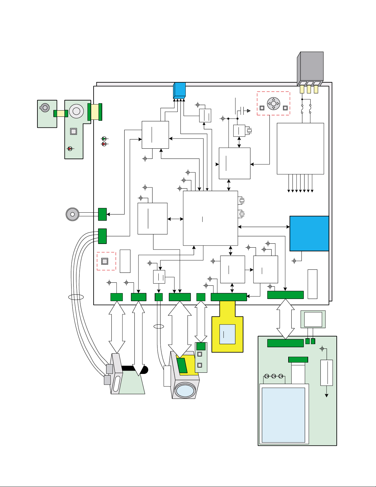
ZOOM PCB
DIAL PCB
MAIN PCB
STROBE UNIT
LENS UNIT
EX PCB
CCD
LCD PCB
SW PCB
LCD
2.0-inch
SD CARD
POWER
SUPPLY
Lithiumion
Battery
NP-40
SD CN
BLOCK DIAGRAM
— 5 —
Page 8
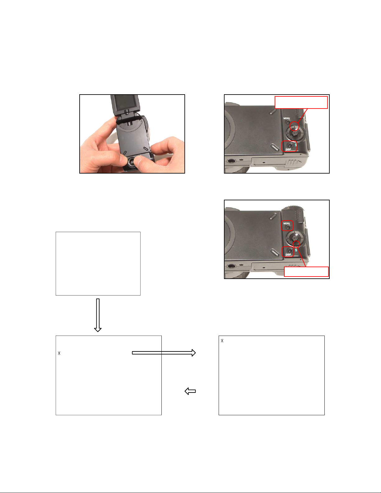
TEST MODE
Note: Never perform the menu items unless otherwise instructed. Doing so may cause destruction
of the data inside, which will make the camera unusable.
■ To boot the test mode
1. While firmly pressing down both [DISP] and [UPPER], turn the power on.
[UPPER] button
2. After the version appears, press buttons in the order of [DOWN], [DOWN], [DISP] and [MENU] in 0.5
second. The diagnostic menu appears.
Ver 1.00
++ KX831 ++
"DOWN" button -> "DOWN" button -> "DISP" button -> "MENU" button
1 :VERSION INFO
2 :VIDEO OUT
3 :USB TCC TEST
4 :TEST MENU
5 :SOUND TEST
6 :IMAGE FLAG
7 :ROM UPDATE
8 :ADJ TEST
9 :REC-INFO
10 :TEST SCRIPT
11 :LAST MEMORY
12 :FORMAT
"SET" button
"MENU" button
[DOWN] button
1 :USB TCC ON
2 :USB TCC OFF
3 :USB STORAGE
— 6 —
Page 9

PROGRAM VERSION UPGRADING
1. To update the firmware version
1. Prepare the memory card which contains the firmware for EX-P505in the root directory.
EX-P505.bin
2. Insert the above memory card into the camera, and set a fully charged battery in the camera.
3. Press the [power button] while holding [MENU] depressed. Keep holding [MENU] depressed until
“PROGRAM UPDATE” appears in the display.
• The following appears.
• The version of the firmware in the memory card appears at the bottom of the display.
NOTE 1) When a wrong software is mistakenly used,
PROGRAM UPDATE
YES
NO
NEW VERSION IS
VER 1.00
(As of February 2005)
the message below appears. Update the
firmware again with the correct software.
FILE ERROR!
0x1002
NOTE 2) When only the version appears in the display
even though you are trying to operate the
camera, charge the battery to the fullest and
try again. The level of the battery indicator
should be highest in order to update the
firmware.
4. Align the white cursor to [YES] by [] and [], and then press [SET].
• “NOW LOADING” appears in the display and the update starts.
5. “COMPLETE” appears after the update finishes.
6. Remove the memory card after turning the power off once. Turn the power back on again while holding
[MENU] depressed, and check the version.
• “VER.1.00” appears.
VER 1.00
(As of February 2005)
7. If the version is correct, turn the power off.
8. Finally, check the operation by recording, playing back and deleting an image.
— 7 —
Page 10

2. How to restore the firmware
1. Prepare the firmware restoration program and change its name as follows;
“rom831_050105.lbn” “venus.bin”
NOTE: This software and procedure automatically restores the firmware even if the firmware belongs
to a wrong model code. Make sure to use the correct software for the correct model.
2. Copy the above file to the root directory in the memory card.
3. Insert the memory card into the camera.
4. Set a fully charged battery in the camera.
NOTE: This software and procedure automatically restores the firmware even if the battery capacity of
the camera is low. Make sure to use a fully charged battery to prevent the danger of power
down during firmware restoration.
5. Turn the power on while pressing the [shutter release] button.
If the power does not turn on only by pressing the power button, insert the battery while holding the
[shutter release] button depressed.
• The LED next to the optical viewfinder changes from “green/red blinking”, “green blinking” to “green steady”.
NOTE: This software and procedure automatically restores the firmware even if the firmware belongs
to a wrong model code. Make sure to use the correct software for the correct mode.
6. When the LED becomes “green steady”, the firmware restoration is finished.
Remove the battery and the memory card, and then turn the power off.
7. Turn the power on again while holding [DISP] and [UPPER] depressed.
Check the model name and the program version (PR:) in the opening screen of the test menu.
++KX831++
Ver 1.00
8. If the model name and the program version are correct, perform SYSTEM INITIAL to initialize the
system area.
“DISP+ UPPER + PW ON” “DOWN, DOWN, DISP, MENU” “7:ROM UPDATE” “5:SYSTEM
INITIAL”
NOTE: After SYSTEM INITIAL is performed, “SYSTEM ERROR” appears when the power is turned
on again.
9. Write the latest firmware.
After the firmware is written, check the model name and the program version (PR:) in the opening
screen of the test menu.
10. Finally, start the camera normally to check the operation by recording, playing back and deleting an
image. Check also that the colors in the images are not too bright or two dark.
— 8 —
Page 11

3. To install the firmware
Initially, firmware is not installed in the PCB supplied by the parts center.
Install the firmware into the PCB after replacing with a new one as shown in the procedures below.
NOTE: The camera does not operate (only LED becomes “green blinking”) if the firmware is not installed
in the PCB.
<Writing the restoration program 1>
1. Copy the following software to the root directly of the SD card.
Restoration software: rom831_050105.lbn
Firmware: EX-P505.bin
2. Change the name as follows;
“rom831_050105.lbn” to “venus.bin”
3. Insert the SD card into the camera.
4. Insert the battery while holding the [shutter release] button depressed.
The LED next to the optical viewfinder changes from “green/red blinking”, “green blinking” to “green
steady”.
5. When the LED becomes “green steady”, remove the battery and turn the power off.
<System Initialize>
1. Boot the test mode.
2. Press [DOWN] twice and then press [DISP], [MENU].
3. Select “7: ROM UPDATE” and then press [SET].
4. Select “5: SYSTEM INITIALIZE” and then press [SET].
5. When the following message appears, press [SET].
SYSTEM INITIALIZE
START….
PUSH OK KEY?
6. The system initialize is executed. Turn off the power when “SUCCESS” appears.
* “SYSTEM ERROR” appears when the camera is turned off without system initialize.
<Writing the firmware>
1. Turn the power on while holding [MENU] depressed.
2. When “PROGRAM UPDATE” appears, select “YES” and then press [SET].
3. “NOW LOADING” appears while the firmware is updated.
4. When “COMPLETE” appears, the firmware update is complete.
5. Turn the power on and off to check if the camera normally functions. If there is no problem, the firmware
update is successful.
— 9 —
Page 12

ADJ TOOL
■ Introduction
Make sure to perform the adjustment by the USB ADJ Tool “adj03SSAW.exe” when replacing the lens
unit or the PCB.
Here the necessary software, driver and setting are explained to use “adj03SSAW.exe”.
Note that the tool, drivers etc. are available only for Windows.
1. Preparation
1-1. Prepare the necessary software, driver and DLL file.
1) Prepare the following three files.
• Testmode driver
[testmode_driver] folder uusbd.dll
uusbd.inf
uusbd.sys
* [testmode_driver_2.0] is for Windows except Windows98.
* [testmode_driver] is for Windows98 only.
• ADJ tool, USB DLL and ADJ setting file
[adj03SSAW] folder adj03SSAW.exe (ADJ tool itself)
uusbd.dll (USB DLL)
* .adt (ADJ setting file. Sorted by models)
* Place all files in the same folder.
2) Place the testmode driver in an appropriate place.
3) Place all of ADJ tool, USB DLL and ADJ setting file in the same folder.
1-2. Set the camera so that it recognizes the USB test mode.
1) Enter the test menu.
Turn the power on while pressing both [DISP] and [UPPER].
Press [DOWN], [DOWN], [DISP] and [MENU].
2) Move the cursor to “3: USB TCC TEST” and press [SET].
3) Move the cursor to “1: USB TCC ON” and press [SET].
4) The USB test mode flag is now saved in the camera. Turn the power off.
5) When the USB test mode flag is ON, the test menu appears first when the camera power is turned on.
* When turning the USB test mode flag OFF, set “3: USB TCC OFF” in the test menu.
1-3. Install the USB driver for the USB test mode in the computer.
(The following is an example using the Windows Me.)
1) Prepare the USB driver for the USB test mode.
2) Turn the camera power on which is set in the USB test mode as shown in 1-2 and let it enter the USB
test mode directly (the test menu appears right after the power is turned on).
3) Connect the camera in the above status to the computer by the USB cable.
4) The “Add new hardware” wizard appears.
5) Check “Designate the place for the driver (for users with sufficient knowledge)” and press “Next”.
6) Check “Search for the optimum driver for the device (recommended)”.
— 10 —
Page 13

9) The file copy starts.
(If a message “uusbd.inf cannot be found” appears during the file copy, designate the same place as
in the step 7).
10) Press “Complete” button.
11) Right-click “My computer”, select “property”, and then open “Device manager”.
If “Universal USB Driver (VMEM manufacturer’s name)”,“USB device for UUSBD” can be found, the
computer has successfully recognized the driver.
12) Installing the test driver into either one enables the other one to recognize it.
* How to uninstall the USB driver for the USB test mode
• Connect the camera to the computer while in the USB test mode so that the computer recognizes
the camera.
• Right-click “My computer”, select “Property” and open “Device manager”.
• Select “USB device for UUSBD” , and then “Universal USB Driver (VMEM manufacturer's name)”.
• Press “Delete” button to delete the driver.
• When using Windows98/98SE/Me, delete the following three files;
(NOTE! Do NOT delete “usbd.inf” and “usbd.sys”, whose names are much alike the following.)
C:windows / inf / uusbd.inf
C:windows / inf / other / KashiwanoUUSBD.inf
C:windows / system32 / drivers / uusbd.sys
• The driver has been successfully deleted.
1-4. Use the USB ADJ Tool
1) Prepare ADJ tool, USB DLL and ADJ setting file in the same folder.
2) Turn the camera power on which is set in the USB test mode and let it enter the USB test mode directly
(the test menu appears right after the power is turned on).
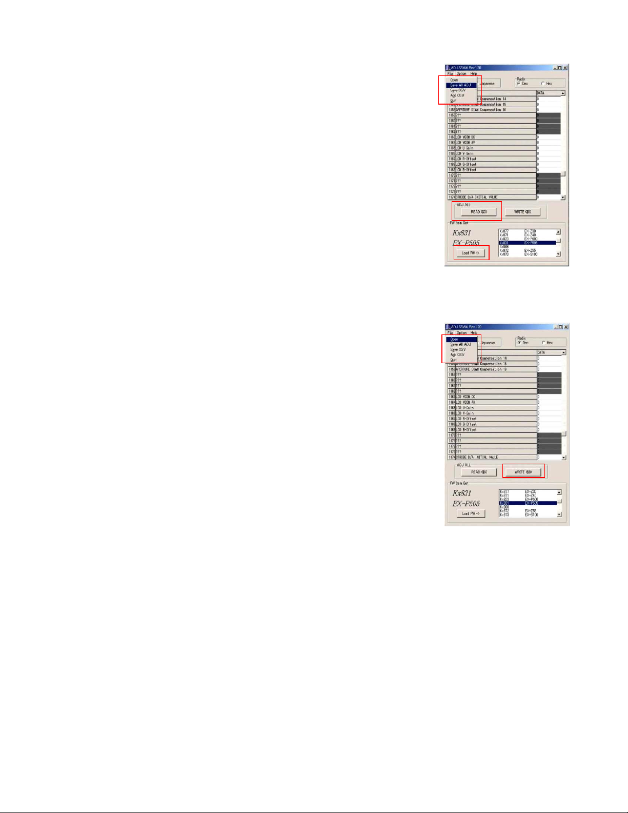
3) Boot “adj03SSAW.exe” and use it as follows;
• To read ADJ data from the camera
앶앸 Press “READ ($9)”.
There is no need to set the model by “FW Item Set”.
• To write ADJ data into the camera
앶앸 Press “WRITE ($8)”.
• To save ADJ data which is read
앶앸 Select “File” and “Save All ADJ”, and save it under an appropriate name.
• Open ADJ data which is saved
앶앸 1. Select the model by "FW Item Set", and then press "Load FW ->" button.
2. Select “File” and “Open”, and open the necessary file.
• Language” radio button can switch the language between Japanese and English in which the name
of the ADJ ITEM is displayed.
• “Radix” radio button can switch the data display between decimal and hexadecimal notations.
— 11 —
Page 14

2. How to use ADJ Tool when replacing Lens unit
Make sure to perform the following procedure after replacing the lens.
A floppy disk with the lens data is bundled in the spare parts of the lens unit.
1 Enter the TEST mode.
1. Turn the power on while pressing both "DISP" and "UP" buttons.
2. Press "DOWN" button, "DOWN" button, "DISP" button, and "MENU"
button while the program version is displayed.
3. Select "3.USB TCC TEST", and press "SET" button.
4. Select "1. USB TCC ON", and press "SET" button.
5. Turn the power OFF.
2 Connect the camera to the computer by the USB cable.
3 Boot "adj03ssaw" .
4 Select the model name and click "Load FW " Key.
• EX-P505
5 Click "ADJ ALL READ", and display the data on the "adj03ssaw".
6 Find the No.1163, "LCD VCOM DC".
7 Write down this value(data).
8 Replace the Lens unit.
9 Perform the above 1 to 3.
6
4
0 Select the model name and click "Load FW " Key.
• EX-P505
A From "File/Open", open the bundled floppy disk, and transfer the data to
the "adj03ssaw".
B Find the No.1163,"LCD VCOM DC"
C Change the data to the former value.(Refer to 7).
D Click "WRITE" button of "ADJ ALL".
E After adjustment, change "1. USB TCC ON" to "2. USB TCC OFF".
A
D
— 12 —
Page 15
3. How to use ADJ Tool when replacing MAIN PCB
Firmware is not installed in spare parts.
1 Enter the TEST mode.
1. Turn the power on while pressing both "DISP" and "UP" buttons.
2. Press "DOWN" button, "DOWN" button, "DISP" button and "MENU"
button while the program version is displayed.
3. Select "3.USB TCC TEST", and press "SET" button.
4. Select "1. USB TCC ON", and press "SET" button.
5. Turn the power OFF.
2 Connect the camera to the PC by the USB cable.
3 Boot "adj03ssaw".
4 Select the model name and click "Load FW " Key.
• EX-P505
5 Click "ADJ ALL READ", and display the data on the "adj03ssaw".
6 Save the data.
7 Replace the MAIN PCB.
8 Writing the Firmware.
Write the firmware into a spare part after replacing one.
NOTE: If a battery is inserted without the firmware, only LED blinks
green and the camera does not operate.
9 Perform the above 1 to 3.
0 Select the model name and click "Load FW " Key.
• EX-P505
A Open the file which is saved above, and display the data on the
"adj03ssaw".
B Click "WRITE" button of "ADJ ALL".
C After adjustment, change "1. USB TCC ON" to "2. USB TCC OFF".
6
5
4
A
B
— 13 —
Page 16

VCOM DC ADJUSTMENT
■ Purpose
Readjust the VCOM value to minimize the flicker of the LCD after replacing the LCD or the main PCB.
■ Necessary tools
1. Camera (Charge its battery fully)
2. Photo diode (S2281-01) : See Fig 1.
3. Photo sensor amp (C2719) : See Fig 2.
4. BNC-BNC cable (E2573) x 2 : See Fig 3.
5. 9-volt alkaline battery (6LR61Y) x 2 : See Fig 4.
6. Oscilloscope
■ Preparation
1. The three tools can be obtained from the following global site.
Photo diode (S2281-01)
Photo sensor amp (C2719)
BNC-BNC cable (E2573)
www.hamamatsu.com/
2. 9-volt alkaline battery is a standard one, but can be obtained from the following global site as well.
www.panasonic.co.jp/global/
Fig1 Photo Diode (S2281-01) Fig2 Photo Sensor Amp (C2719)
Fig3 BNC-BNC Cable (E2573) Fig4 6LR61Y
— 14 —
Page 17

■ Procedure
2:LCD
1:ADJ STAT CLR
3:LENS
.
.
.
1:VCOM OK
.
.
.
OK -> Register Write
VCOM = 0xca
This value is an example and differs by products.
Figure (a)
Figure (b)
Figure (c)
Figure (d)
1 :VERSION INFO
2 :VIDEO OUT
3 :USB TCC TEST
4 :TEST MENU
5 :SOUND TEST
6 :IMAGE FLAG
7 :ROM UPDATE
8 :ADJ TEST
9 :REC-INFO
10 :TEST SCRIPT
11 :LAST MEMORY
12 :FORMAT
1. Camera setting
a) Turn the power on while pressing “DISP” and “UPPER”.
After pressing “DOWN” key twice, press “DISP” and “MENU”.
Figure (a) appears.
b) Select “8 : ADJ_TEST” and then press SET.
(See Figure (b).)
c) Next, select “2. LCD” and then press SET.
(See Figure (c).)
2. Connecting the TOOL
d) Pressing SET causes the right figure to appear.
(See Figure (d).)
a) Place two 9-volt alkaline batteries in C2719.
b)
Connect the output terminal of C2719 to the channel terminal of the oscilloscope by the BNC-BNC cable.
c) Connect the input terminal to the Photo Diode by the BNC cable.
d) Turn the oscilloscope and C2719 on.
* Pull the ON/OFF switch of C2719 this way and raise/lower it. (See below Figure.)
— 15 —
Page 18

3. Measurement
a) Connect S2281-01 to the camera’s LCD monitor (see below).
AC Waveforms appear on the monitor screen of the oscilloscope.
* Change the Rf range of C2719 in case the range does not match.
Photo diode
S2281-01
INPUT OUTPUT
Oscilloscope
Photo sensor amp
CAMERA
BNC-BNC cable
LCD
Minimize the
ripple components
b) After AC waveforms of the oscilloscope appear , minimize it by pressing the camera’s up/down buttons
(see the picture).
Make sure to visually check if it has been minimized.
[UPPER] button
After it has been minimized, press SET key.
The screen in the right figure appears and the new VCOM
is written (VCOM adjustment is finished.).
Return to the previous display by pressing MENU or PW key.
[DOWN] button
OK -> Register Write
VCOM = 0xca
ADJ DATA SET!
This value is only an example, and differs by products.
— 16 —
Page 19

CURRENT CONSUMPTION
(1) Current consumption
Input Voltages Type
Operation mode DC JACK Battery Terminal
Product Mode TEST mode Product Mode TEST mode
Input Voltage 4.50 ± 0.01V 3.70 ± 0.01V
PLA Y 350 mA and below 400 mA and below 380 mA and below 430 mA and below
REC 460 mA and below 510 mA and below 500 mA and below 550 mA and below
Power OFF 1 mA and below 500 µA and below
(2) The battery indicator changes according to the voltages as follows.
* The voltage is measured between P100 and P101.
• DC in = less than 3.67 ± 0.02V:
• DC in = less than 3.59 ± 0.02V: (PLAY mode)
• DC in = less than 3.40 ± 0.02V:
(PLAY mode)
(PLAY mode)
THE COUNTERMEASURE FOR "SYSTEM ERROR"
System error may occur when the battery is removed while data is written to the internal memory.
■ PROCEDURE
1. Initialize the system.
a) Enter the TEST mode.
b) Select "7:ROM UPDATE" and press SET button.
c) Next, select "5:SYSTEM INITIAL" and press SET button.
d) The following message appears.
SYSTEM INITIALIZE
START
PUSH OK KEY?
e) Press SET button and System is initialized.
"SUCCESS !" appears on the monitor.
2. Write firmware.
Refer to the "1. To update the firmware version" on page 7.
Write the firmware.
If the TEST mode boots automatically, change "USB TCC ON" to "USB TCC OFF".
Replace the Main PCB if the camera does not recover.
...
— 17 —
Page 20

DISASSEMBLY
■ Make sure to use correct screws when assembling since
there are several kinds of them.
It is a good idea to sort them as shown in the right when
disassembling.
1. Remove the battery.
■ Removing the Rear case Assy
2. Remove six screws.
Screw (S1)
Screw (S1)
3. Remove the R case Assy.
Screw (S1)
Rear case Assy
— 18 —
Page 21

■ Removing the Main PCB
4. Remove one screw, and then the Top case Assy.
Screw (S1)
5. Remove three screws.
Unsolder three lead wires (GND).
Remove five connectors.
Tip: Unsolder the earth terminal which is
attached to the connector in the center.
Remove one FPC.
Connectors
Top case Assy
ÉgÉbÉvÉPÅ[ÉXÉAÉbÉVÅ[
lead wires
Earth
lead wires
FPC
6. Pull out the main PBC to some extent, and then remove one connector and one FPC.
7. Lift the main PCB, and then remove two connectors and the main PCB.
Connector
Connectors
FPC
Screw (S2)
Main PCB
— 19 —
Page 22

■ Removing the Front case Assy
8. Remove one screw, and then the Front case Assy.
Screw (S1)
Front case Assy
NOTE: Discharge the strobe condenser when
removing the front case. Use 3 KΩ cement
resistance as the discharge tool.
■ Removing the Battery case Assy
9. Remove one screw, and then the Battery case Assy.
Screw
Battery case Assy
— 20 —
Page 23

■ Removing the Dial unit
10. Remove one screw, and then the Dial unit.
Screw
Assembly Precautions:
1 Align the dial in the correct direction.
2 Assemble the dial PCB in the front case.
11. Remove the tape, and then remove one screw.
12. Remove two FPCs, and then the Dial PCB.
Tape
3 Set the dial in while correctly aligning its
direction.
4 Fix it by a screw.
FPC
Screw (S2)
13. Remove two Hooks, and then the Zoom PCB.
14. Remove the Speaker unit.
Tip: The speaker unit is fixed by double-sided tape.
Hooks
Zoom PCB
Dial PCB
Speaker unit
— 21 —
Page 24

■ Removing the LCD unit
15. Remove two screws, and then the Side case Assy.
Tip: It is easier to remove the side case when the strobe is ejected.
Assembly Precautions: Do not forget to fix the earth wire.
Earth
Screw (S3)
16. Remove two screws, and then the LCD unit.
Screw
Side case Assy
17. Remove two screws, and then the Hinge cover.
Tip: The hinge cover is fixed with two hooks.
Hook
Screw (S4)
Assembly Precautions: There is a possibility that the LCD cables are disconnected.
Make sure to fix the hinge cover correctly.
OK
Partition Wall
LCD unit
Screw (S4)
Hook
NG
— 22 —
Page 25

18. Remove two screws, and then the LCD case.
Tip: Pay attention to the six hooks.
Screw (S4)
19. Unsolder two lead wires.
20. Remove one connector, and then the LCD assy.
Connector
lead wires (White)
Hooks
LCD case
LCD assy
lead wires (Black)
21. Remove two screws, and then the LCD case.
22. Remove one screw, and then the SW PCB.
Screw (S3)
LCD case
Tip: Removing / fixing the LCD cables
Let the cables through the hinge when removing and fixing them.
Screw
SW PCB
— 23 —
Page 26

■ Removing the CAM RING ASSY
23. Remove two screws, and then the Cam ring Assy.
Screw (S1)
■ Removing the Strobe unit
24. Remove two screws, and then the Strobe unit.
Screw (S1)
Cam ring Assy
Assembly Precautions: Wire the lead wire for the strobe magnet inside the strobe.
OK
25. Remove two screws and two connectors, and then the Strobe unit.
There are connectors on both front and back sides.
Screws
Strobe stopper
NG
Connector
Connector
— 24 —
Page 27

26. Unsolder four lead wires, and then remove the strobe PCB (with condenser).
Strobe unit
Strobe PCB
(with condenser)
27. Remove one screw, and then the MAG base.
lead wire (Red)
lead wire (Green)
lead wire (Orange)
lead wire (Black)
Assembly Precautions:
Make sure to fix the magnet in the
correct direction, which can be judged by
the color of the lead wires (see below).
OK
NG
lead wire (Red)
Assembly Precautions:
Fix the lead wires for the magnet with
tape as shown below.
lead wire (Red)
— 25 —
Page 28

28. Pull the shaft while holding the spring with your fingers.
Disassemble the strobe unit into the following parts; shaft, bracket, spring, cover and the case.
Assembly Procedure:
1 Let the bracket through the spring.
Pay attention to the direction of the spring.
Spring
Case
Bracket
Cover
Shaft
2 Set the bracket and the spring which are
assembled as a set in the case.
3 Let the shaft in as shown in the figure
and complete the strobe unit.
— 26 —
Page 29

29. Remove the strobe lower cover.
Assembly Precautions:
1 Separate the lead wires from the strobe
into the right and left sides.
lead wires (Black)
lead wires (Red, Green, Orange)
30. Remove two screws, and then the Strobe cover.
Disassemble the unit into the strobe, case and cover.
Tip: Pay attention to the hooks.
2 Fix the strobe lower cover.
Screw (S3)
Assembly Precautions:
When assembling the strobe in the case,
make sure not to pinch the lead wires
between the case and the strobe.
Hooks
OK
— 27 —
Page 30

31. Remove the MIC.
Tip: The speaker unit is fixed with double-sided tape.
MIC unit
■ Removing the LENS UNIT
32. Remove six screws, and then the LENS UNIT.
Screw (S3)
Screw (S3)
Screw (S3)
Assembly Precautions:
Store the cables inside the case.
Screw (S3)
LENS UNIT
— 28 —
Page 31
19
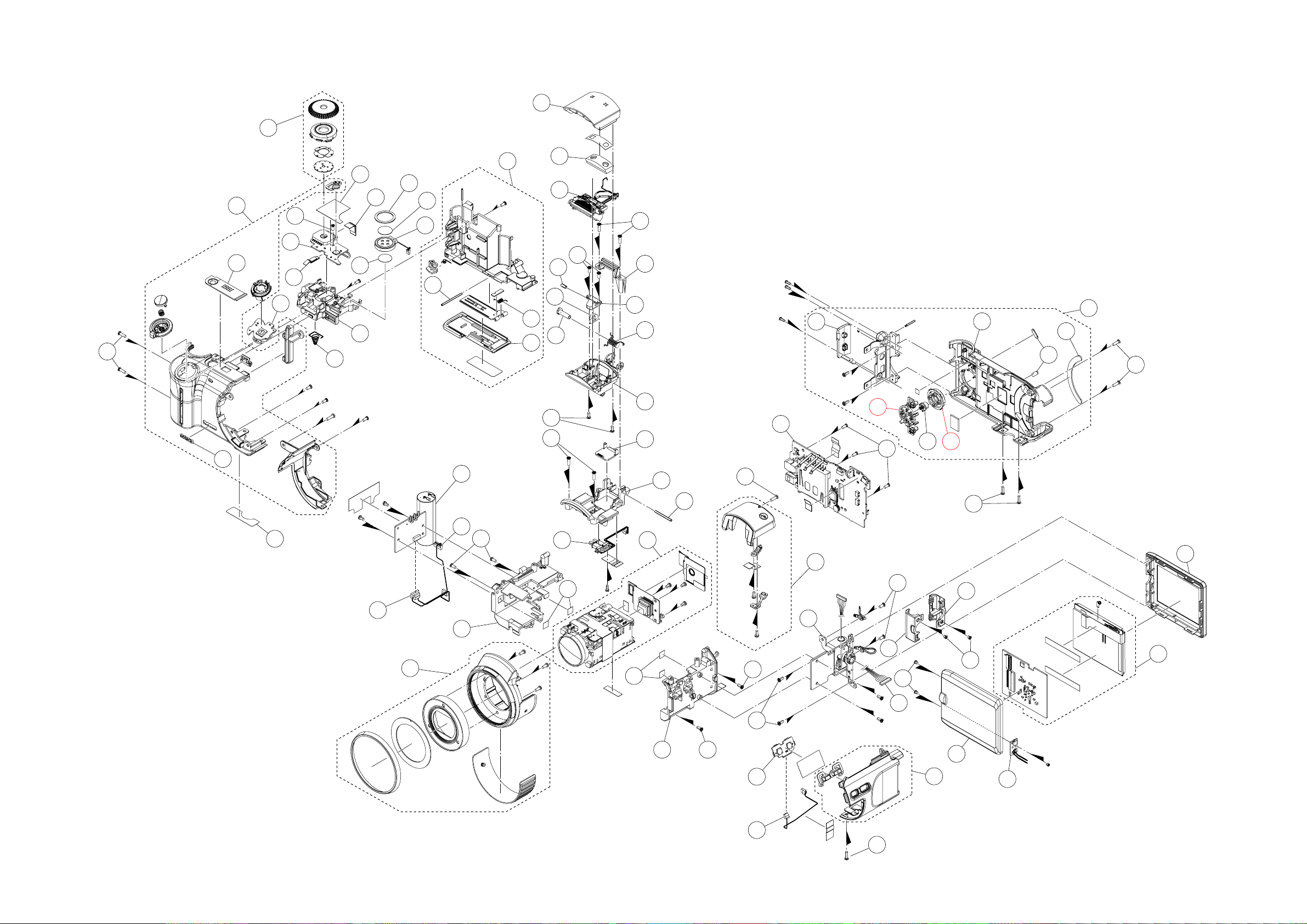
EXPLODED VIEW
1
S1
33
31
32
26
25
27
S2
30
24
23
29
28
20
21
22
16
34
15
17
18
S3
S1
2
3
S1
S3
7
9
6
4
8
5
10
11
12
48
51
46
S2
S1
52
53
4950
47
54
S1
63
36
37
35
38
S3
14
39
39
40
13
S1
45
S3
60
62
S3
S4
59
S3
S341
42
44
61
S4
57
58
55
56
— 29 —
43
S1
Page 32

PARTS LIST
Specification R RemarkN Item Parts Code Parts Name
N 1 1018 6609 COVER/STROBE RJK506999-001V01 1 AM X
N 2 1018 6626 MICROPHONE KKM5002-010010 1 BA C
N 3 1018 7365 STROBE UNIT XEST-K831-1 1 BE B
N 4 1018 6584 STOPPER/STROBE RJK507003-001V01 1 AB X
N 5 1018 6566 SPRING/STROBE RJK507002-001V01 1 AA C
N 6 1018 6567 BRACKET/STROBE RJK507062-001V01 1 AA C
N 7 1018 6608 SHAFT/MAG RJK506998-001V01 1 AA C
N 8 1018 6607 CASE/MAG RJK506997-001V01 1 AA C
N 9 1018 6625 PLATE/MAG JTM5011-060100 1 AE C
N 10 1018 6606 CASE/STROBE RJK506996-001V01 1 AD C
N 11 1018 6610 COVER/STROBE RJK507000-001V01 1 AB C
N 12 1018 6589 CASE/TOP RJK506995-001V01 1 AE X
N 13 1018 6565 SHAFT/STROBE RJK507001-001V01 1 AA C
N 14 1018 6587 BASE/MAG JTM5011-010100 1 AO X
N 15 1018 6517 CASE ASSY/BATTERY RJK506963*001V01 1 AU C
N 16 1018 7407 SHAFT/BATTERY RJK507032-001V01 1 AA C
N 17 1018 7408 COIL/BATTERY RJK507033-001V01 1 AA C
N 18 1018 7405 COVER/BATTERY RJK507034-001V01 1 AG C
N 19 1018 6520 DIAL ASSY RJK506978*001V01 1 AT C
N 20 1018 6551 CUSHION/SPEAKER RJK507338-001V01 1 AA C
N 21 1018 8041 NET/SPEAKER RJK507417-001V01 1 AA C
N 22 1018 6529 SPEAKER HDR9153-010050 1 AR C
N 23 1018 6550 TAPE/SPEAKER RJK507336-001V01 1 AA C
N 24 1018 8040 TAPE/DIAL RJK507416-001V01 1 AA C
N 25 1018 8238 PCB ASSY/DIAL RJK506987*001 TK 1 BK C
N 26 1018 8239 PCB ASSY/ZOOM RJK506987*002 TK 1 BA C
N 27 1018 6530 CABLE RJK506938-001V01 1 AB C
N 28 1018 6544 CABLE RJK506937-001V01 1 AB C
N 29 1018 6533 CASE/BATTERY RJK507025-001V01 1 AC C
N 30 1018 6534 SPRING/BATTERY RJK507026-001V01 1 AA C
N 31 1018 6527 CASE ASSY/FRONT RJK506969*001V01 1 BT C
N 32 1018 6570 PLATE/PW RJK507018-001V01 1 AR C
N 33 1018 6571 PLATE/NAME RJK507058-001V01 1 AE C
N 34 1018 7364 PCB ASSY/STROBE XEST-K831-2 1 BZ B
N 35 1018 6562 CABLE/STROBE RJK506935-001V01 1 AJ C
N 36 1018 6563 CABLE/STROBE RJK506936-001V01 1 AM C
N 37 1018 6585 CAM RING ASSY RJK506970*001V01 1 BR C
N 38 1018 6581 HOLDER/LENS RJK506982-001V01 1 AE C
N 39 1018 6582 TAPE/LENS RJK506983-001V01 4 AA X
N 40 1018 8242 LENS UNIT RJK507367*001 TK 1 EH A FD attached
N 41 1018 6580 HOLDER/LENS RJK506981-001V01 1 AD X
N 42 1018 8240 PCB ASSY/EX RJK506987*003 TK 1 AU C
N 43 1018 6561 CABLE/EX RJK506934-001V01 1 AG C
N 44 1018 6528 CASE ASSY/SIDE RJK506975*001V01 1 AV C
N 45 1018 6518 CASE ASSY/TOP RJK506965*001V01 1 AR C
N 46 1018 8237 PCB ASSY/MAIN RJK507366*001 TK 1 EG A
N 47 1018 6513 CASE ASSY/REAR RJK506960*001V01 1 BJ C
N 48 1018 6549 COVER/JACK RJK507046-001V01 1 AC C
N 49 1018 6524 BUTTON/CS RJK507041-001V01 1 AA C
N 50 1018 6545 BUTTON/SET RJK507042-001V01 1 AA C
QTY Price
Overs Code
N: new parts
*1, *2, *3 and *4 are provided as a set.
1 set : 4pcs. × *1,*2,*3 and *4 = 16 pcs.
— 30 —
Page 33

N Item Parts Code Parts Name Specification R Remark
N 51 1018 6546 BUTTON/MENU RJK507043-001V01 1 AA C
N 52 1018 6522 CASE/REAR RJK507040-001V01 1 AT C
N 53 1018 6523 RUBBER RJK507048-001V01 2 AD X
N 54 1018 6525 RUBBER RJK507047-001V01 1 AH X
N 55 1018 6617 CASE/LCD RJK506988-001V01 1 AK C
N 56 1018 8236 LCD ASSY RJK507374*001 TK 1 DH B
N 57 1018 6618 CASE/LCD RJK506989-001V01 1 AO C
N 58 1018 8241 PCB ASSY/SW RJK506987*004 TK 1 AT C
N 59 1018 6600 CABLE/LCD RJK506933-001V01 1 BD C
N 60 1018 6603 HINGE UNIT ST1486A007 1 BY C
N 61 1018 6619 COVER/HINGE RJK506990-001V01 1 AG C
N 62 1018 6620 COVER/HINGE RJK506991-001V01 1 AG C
N 63 1018 6514 LABEL/RATING RJK507055-001V01 1 AA X For EU/US
N 63 1018 6542 LABEL/RATING RJK507055-002V01 1 AA X Except EU/US
N S1 1018 7652 SCREW RJK507382-003V01 12 AA X
N S2 1018 6543 SCREW RJK502971-003V01 4 AA X
N S3 1018 7650 SCREW RJK507382-001V01 21 AA X
S4 1017 1879 SCREW RJK502970-006V01 4 AA X
N FU100 1018 9324 FUSE FCC10152ABPA 1 AA B
N FU101 1018 9325 FUSE FCC10102ABPA 1 AA B
ACCESSORIES
N - 1018 7438 STRAP ST-K831-S 1 AP X
- 1019 3595 BATTERY/LI-ION MK11-2768 1 BY B
- 1015 6662 CHARGER R68-8186 1 BZ C For US
- 1015 6663 CHARGER R68-8187 1 BZ C Except US
- 1015 6664 AC CORD CBL-K871-AC-EU 1 AG C EU type
- 1015 7018 AC CORD CBL-K871-AC-JU 1 AH C Blade type
- 1015 7858 AC CORD CBL-K871-AC-UK 1 AT C UK type
N - 1018 7439 USB CABLE TYX6503-010100 1 AR C
N - 1018 7440 VIDEO CABLE TYX6504-010100 1 AQ C For EU/US
N - 1019 3955 VIDEO CABLE TYX6504-110107 1 AT C Except EU/US
N - 1019 3306 CD ROM CK831DCA01R 1 AF C
N - 1019 3307 CD ROM CK831DCA02R 1 AF C
N - 1018 7446 CAP/LENS RJK507049*001V01 1 AI C
N - 1018 7437 HOLDER/CAP CH-K831-S 1 AB C
N - 1019 3308 HOOD/LENS RJK507052-001V01 1 AD C
QTY Price
Overs Code
N: new parts
*1, *2, *3 and *4 are provided as a set.
1 set : 4pcs. × *1,*2,*3 and *4 = 16 pcs.
— 31 —
Page 34

MAIN PCB (TOP VIEW)
PRINTED CIRCUIT BOARDS
— 32 —
Page 35

MAIN PCB (BOTTOM VIEW)
— 33 —
Page 36

SCHEMATIC DIAGRAMS
— 34 —
Page 37

— 35 —
Page 38

— 36 —
Page 39

Ver.1 : Mar. 2005
• Correction of pages 30 and 31
Ver.2 : Apr. 2005
• Replacement of the ADJ TOOL (P10 ~ 11)
• Replacement of the PARTS LIST (P30 ~ 31)
Ver.3 : Feb. 2006
• Replacement of the EXPLODED VIEW (P29)
CASIO COMPUTER CO.,LTD.
Overseas Service Division
6-2, Hon-machi 1-Chome
Shibuya-ku, Tokyo 151-8543, Japan
 Loading...