

Page 1
SERVICE MANUAL
ELECTRONIC CASH REGISTER
V-R200
(EX-843)
JUL. 2016
Ver.3 : Jun. 2017
Page 2

V-R200 / VER.1
CONTENTS
IMPORTANT NOTICE ....................................................................................... P. 1
PRODUCT SPECIFICATIONS .......................................................................... P. 8
DIAGNOSTIC OPERATION ............................................................................. P. 12
DISASSEMBLY/ASSEMBLY ........................................................................... P. 33
CIRCUIT DIAGRAM .........................................................................................P. 59
EXPLODED VIEW/PARTS LIST ...................................................................... P. 63
Page 3
V-R200 / VER.1
– 1 –
IMPORTANT NOTICE
1.
Safety Precautions ................................................................................... P. 2
2.
Precautions for Use ................................................................................. P. 3
3.
Information
3-1. Basic Operation .................................................................................................... P. 5
3-2. SD/SDHC memory card ........................................................................................ P. 7
Repair Information
When the main PCB is replaced with a spare part one.
• Since an OS is already installed on the spare part main PCB, update the OS to an appropriate
version as required.
Refer to: Diagnostic operation
2. UPDATING the OS
• Write the serial number.
Refer to: Diagnostic operation
1-6. Checking and Registering the Serial Number
When the IOC PCB is replaced with a spare part one.
• Firmware is already installed on it.
• The fi rmware version is confi rmed at power on and, if necessary, it is automatically updated.
• UUID setting is not required.
When the CASE ASSY/FRONT is replaced with a spare part one.
• Carry out the touch panel calibration.
Refer to: Diagnostic operation
1-4. Touch panel calibration
To carry out the Diagnostic operation, a dedicated application is needed to be installed
beforehand.
NOTE: After completion of the test, make sure to uninstall the test application.
Page 4
V-R200 / VER.1
– 2 –
1.
Safety Precautions
*
Caution
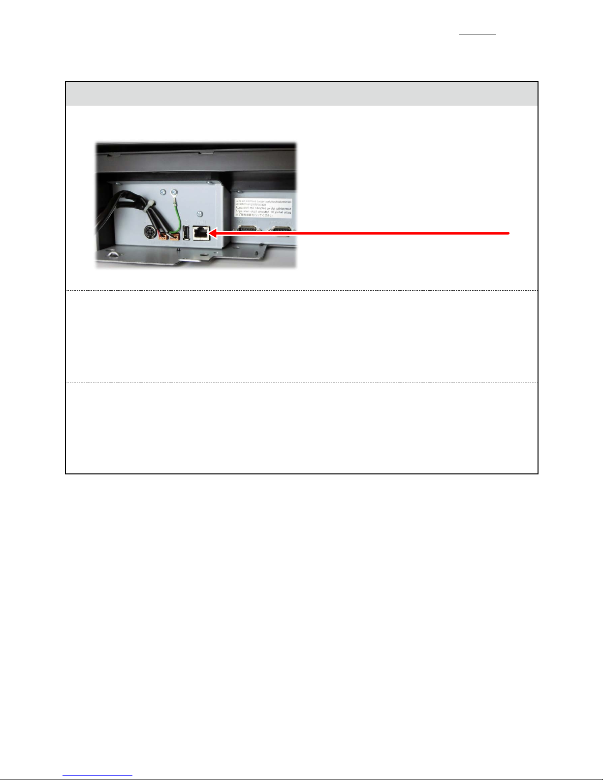
LAN Conenector
Ethernet (LAN) Connector:
Not used to a telecommunication network
To Prevent malfunctions caused by the weak batteries, charge the memory
protection batteries for over 6-hours.
1. Before installation, initialize the terminal and leave it power on over 6-hours.
2. After the terminal is repaired or checked, you must leave it power on over 6-hours.
BATTERIES HANDLING PRECAUTIONS
1. Do not use old and new batteries mixed together, or batteries at different charge levels.
This may cause leakage of battery fl uid and heat generation.
2. Load a set of three new batteries at being care of their polarity.
Page 5

V-R200 / VER.1
– 3 –
2.
Precautions for Use
Read the following items thoroughly and use this product properly. CASIO bears no responsibility whatsoever
for malfunction or damage caused by handling not following below contents. Please note that it will also result in
charged repair, and actual cost required for repair will be charged, even if it is within the warranty period.
Installation Location
Do not place in a hot or dusty location, or in any location exposed to oily smoke or water. Never store or leave in
following locations. This could erase the memory and cause a malfunction or result in deformation of the case.
0
Temperature of 0 °C or lower
0
Inside vehicles in summer
0
Close to air conditioner
0
Under direct sunlight
0
Temperature of 40 °C or higher
Avoid using this product in following locations.
0
Outdoor
0
Close to equipment that will become hot such as range, electrical heater, etc.
0
Location exposed to water or steam
0
Location with severe change in environment such as temperature, humidity, etc.
0
Location where corrosive gas or saline matter is generated
0
Location where dirt or dust is generated
0
Location with vibration
0
Location prone to static electricity
Other
0
Prepare separate AC power supply from the power line for motor, ice maker, microwave oven, etc., which may
generate noise.
0
Do not touch the power switch with wet hands. This may result in electrical shock.
0
Wipe thoroughly with dry cloth, etc., when there is any water droplet on the device.
0
Do not use any volatile chemical such as thinner, benzine, cosmetics, etc., for cleaning. Wipe with dry soft cloth
when this product gets dirty. The display section may be scratched when scuffed strongly with a cloth.
0
When the capacity of the internal memory protection battery is insuffi cient ant there is no power supply available
due to a power outage, malfunction or other reason, the memory content might be erased.
0
Contact the dealer or the CASIO service representative around 5 years after purchase to replace the battery (this
time depends on how the product is used).
Page 6
V-R200 / VER.1
– 4 –
Take Advance Notice of the Following
0
The content of this manual may be changed without prior notice due to improvement or specifi cation change of
the product.
0
Please note that CASIO bears no responsibility for damage, loss of profi t, or any claim from third party due to
loss or change of data caused by usage, malfunction, or repair of this product.
0
The copyright for this manual and all rights related to the software described in this manual are the property of
CASIO Computer Co., Ltd. The unauthorized reproduction of this manual in whole or part is prohibited without
the written permission of CASIO.
0
The screen or illustration used in this manual may be different from the actual product. The keys and icons are
described in simplifi ed manner.
0
Weld Line
The line on the exterior of the product is called “weld line”, which is created at the time of plastic forming, and it is
not a crack or a scratch. This will not interrupt the usage.
Trademark Registration
SD, SDHC, microSD and microSDHC are trademarks of SD-3C, LLC.
Page 7
V-R200 / VER.1
– 5 –
3.
Information
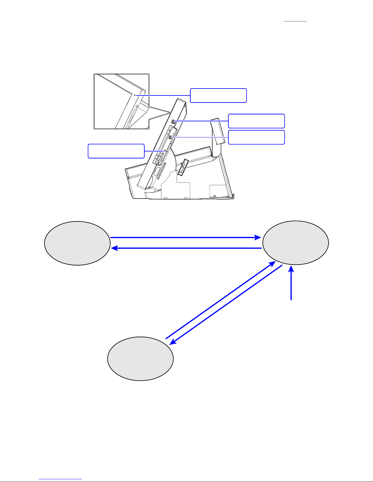
3-1. Basic Operation
(1) General information
Fig. 1
Maintenance switch
Power switch
Power lamp
Reset switch
Fig. 2
• The power switch is pressed.
• When touching the touch panel.
• An alarm occurs.
• The reset switch is pressed.
¨ Reboot without shutdown
• The power switch is pressed.
• No operation is done for a certain period of time.
• The power switch is pressed.
• The reset switch is pressed.
¨ Reboot without shutdown
• The power switch is held down more than 5 sec.,
then choose "Power off".
• The maintenance switch is held down more than 5 sec.
OFF state
Power lamp: OFF
ON state
Power lamp: Green
Sleep state
Power lamp: Orange
NOTE: Power lamp: Red (Insuffi
cient capacity of the internal memory backup battery)
Do not shutdown the power supplied to the product or unplug the power cord.
NOTE: After taking out a product from carton box, connect AC adaptor to the product then leave it more than
6hours to charge internal memory buck up battery for full charge.
Page 8
V-R200 / VER.1
– 6 –
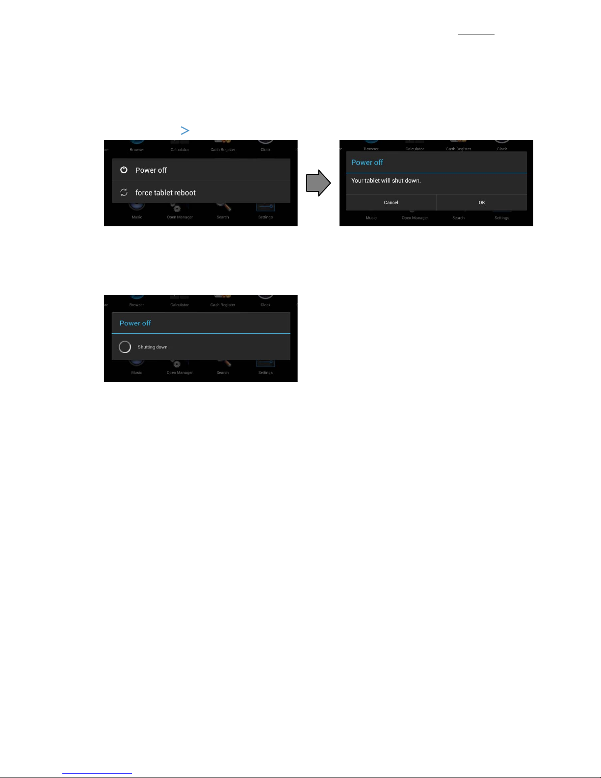
(2) Shutdown procedure
There are two ways to shut down.
0Shutting down by the power switch
Press and hold the power switch until “Power off” / “force tablet reboot” appears.
Select “Power off”
“OK”.
Fig. 3 Fig. 4
0Shutting down by the maintenance switch
Press and hold the maintenance switch until “Pwer off” appears.
Fig. 5
Page 9
V-R200 / VER.1
– 7 –
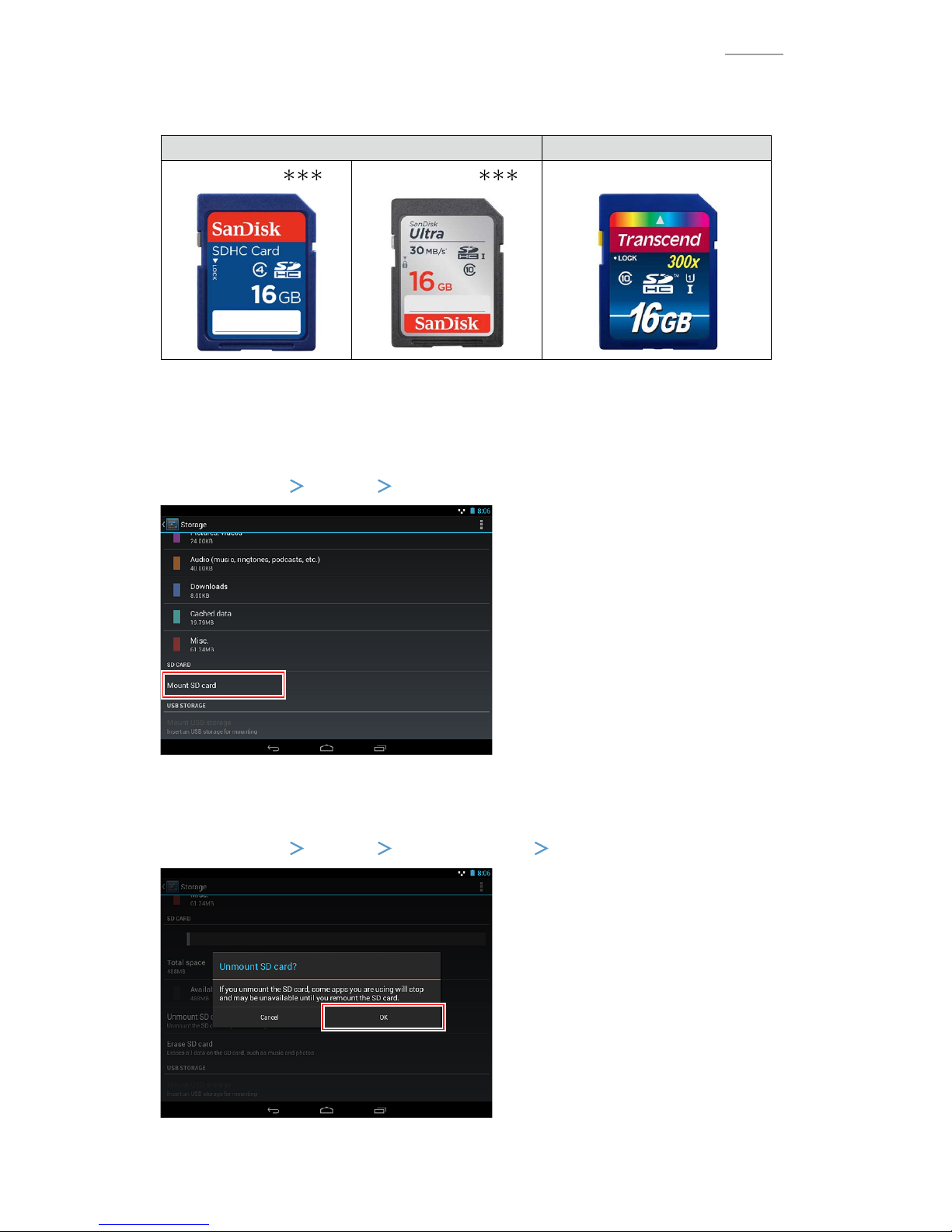
3-2. SD/SDHC memory card
(1) Recommended SD/SDHC memory card
SanDisk Corporation Transcend Information, Inc.
SDSDB-016-
SDSDUL-016-
TS16GSDU1
Fig. 6
(2) Mounting the SD/SDHC memory card
SD/SDHC memory card is automatically mounted when it is inserted. If it has been unmounted due to
incorrect operation, mount it again.
Select “Settings”
“Storage”
“Mount SD card”.
Fig. 7
(3) Unmounting the SD/SDHC memory card
Select “Settings”
“Storage”
“Unmount SD card”
“OK”.
Fig. 8
Page 10
– 8 –
V-R200 / VER.1
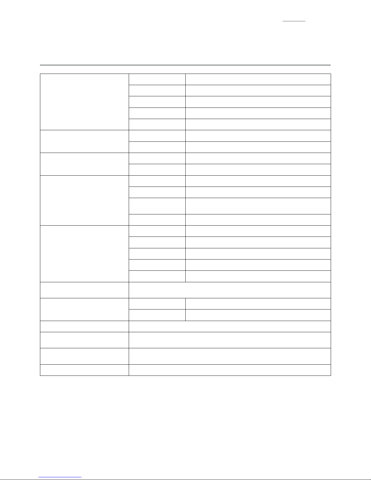
PRODUCT SPECIFICATIONS
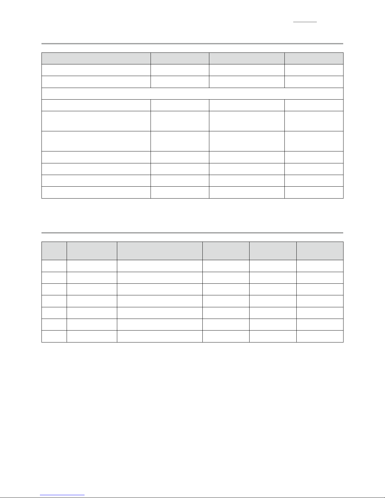
YSpecifi cations List
Main display
Type 10.4 SVGA color TFT LCD
Resolution 800 × 600
Color *1 Max. 16.77 million colors
Backlight White LED
Other Power tilt function (15° to 75°)
Touch panel
Method 4-wire resistive fi lm
Size 10.4 inch
Sub display
Resolution 32 × 160 dot (20 single-byte characters, 2 lines)
Backlight 2 colors (emerald green, white)
Printer
Print method Thermal printer
Print speed *1 Max. 120 mm/sec.
Paper roll
Thermal recording paper, width 58 mm or 80 mm,
external diameter 80 mm or smaller
Paper cut-off Automatic cutter
Memory protection *2
Battery Nickel-metal hydride rechargeable battery
Memory holding *3 Approximately 1 hour (used at 25 °C)
Battery life *4 5 years (used at 25 °C)
Charge time Full charge in 6 hours (used at 25 °C)
Time holding Approximately 30 days (used at 25 °C)
Power supply/
power consumption
120 V ac ±10 V 50/60 Hz 0.64 A (Operating) 0.2A (Standby)
220 V to 240 V ac ±10 V 50/60 Hz 0.36 A (Operating) 0.11A (Standby)
External interface
Side of display SD/SDHC memory card slot x 1
Back of the device COM port x 3, LAN port x 1, USB port x 1, DC jack x 1
Water proof performance IP53 level (main display only) *5
Temperature/humidity
(when in use)
0°C to 40°C/20% to 85% RH
External dimensions
W 395 mm x D 237 mm x H 229 mm
(With maximum tilt angle) (Not including protruding parts)
Weight Approximately 4.0 kg
*1: These fi gures indicate the performance level of the hardware. The actual colours and speed vary depending on
the application in use.
*2: The internal battery is a consumable item. Contact the dealer or the CASIO service representative around
5 years after purchase to replace the battery (this time depends on how the product is used). Memory protection
may not operate properly if the battery becomes depleted.
*3: After 1 hour of disconnect power, the product will shut itself down. To turn the power ON, press the power
switch after power recovery.
*4: With a battery usage frequency of once per month.
*5: The specifi cations here are test values, and are not guaranteed values.
Page 11
– 9 –
V-R200 / VER.1
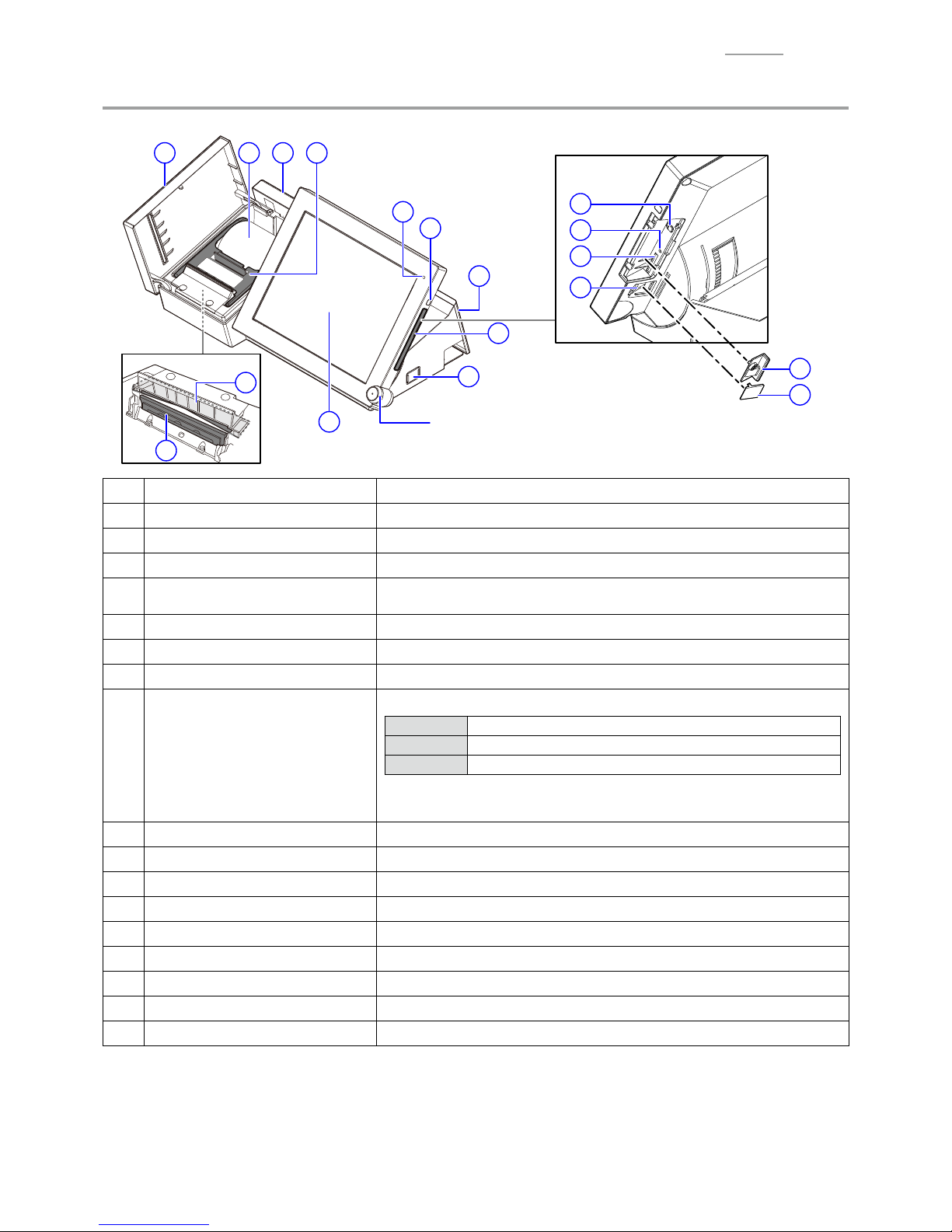
YParts Names and Functions
15
12
13
14
Dallas key
For operators to sign on and off. (Factory option)
Front
1
2
11 10 4
6
18
16
17
5
8
9
7
3
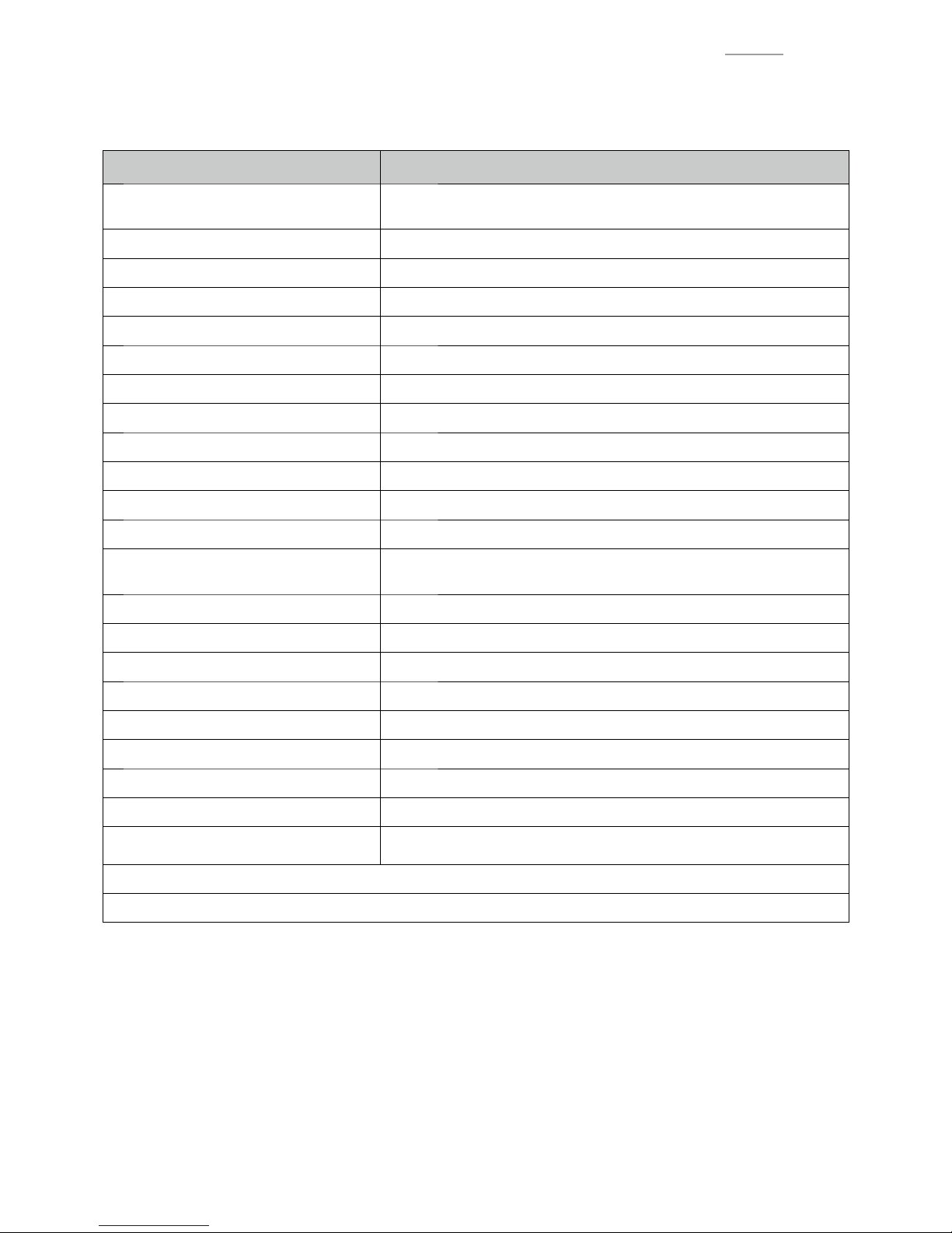
1 Printer cover Open this replacing the paper roll. Keep closed during normal use.
2 Printer head Prints the receipts.
3 Auto cutter block The customer receipt is cut automatically when it is issued.
4 Paper holder Open this when replacing the paper roll.
5
Main display and touch screen
panel
Display each menu. Used for data input.
6 Side cover Cover for SD/SDHC memory card slot.
7 Connector cover Open when connecting the power supply or various devices.
8 Power switch Turn the power ON. Switch the ON and OFF of the main display.
9 Power lamp
Display the status of the power supply.
Green Starting
Orange Main display OFF
Red Insuffi cient internal memory protection battery capacity
NOTE: When the power lamp is red, do not shut down the power or
remove the power plug.
10 Sub display Displays information for customers.
11 Paper roll Insert the roll of paper used for receipts, etc.
12 SD/SDHC memory card slot Insert the SD or the SDHC memory card.
13 Card cover Cover for the SD/SDHC memory card slot (screw lock).
14 Boot cover Boot cover
15 Boot switch Boot device setting *User operation prohibited.
16 Reset switch Reboot without shutdown *User operation prohibited.
17 Maintenance switch Shutdown (by a long press) *User operation prohibited.
18 Tilt switch Adjusts the angle of the main display.
NOTE 1: Do not put your fi ngers in the Auto cutter unit while the receipts are being cut. This may result in
injury.
NOTE 2: Before removing the power plug or turning the breaker off for moving or cleaning the product, for
example, make sure to shut down the power by pressing and holding the power switch. The data
may be damaged or the product may be broken if the above procedure is not done properly.
Page 12
– 10 –
V-R200 / VER.1
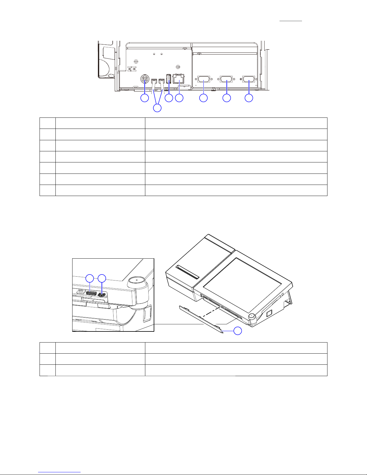
Rear
19181715
16
20 21
15 DC jack Connect the AC adaptor.
16 Drawer connecting cable Cable for connecting to the drawer.
17 USB port Connect the USB device. *1
18 LAN port Connects with external devices via a hub. *1
19 COM3 port Connect device such as printer, etc. *1
20 COM2 port Connect device such as printer, etc. *1
21 COM1 port Connect device such as printer, etc. *1
*1: Use the recommended product. For detailed information, contact your sales outlet.
Front
22
23 24
22 Sheet cover Connector cover
23 Serial console connector Connector for development (not used )
24 microUSB port Connector for development (not used )
Page 13
– 11 –
V-R200 / VER.1
YOption List
Device name Model Specifi cation Note
Remote printer (RS-232C port) UP-370B EX-PRT-UNIT-11B
Remote printer (RS-232C / LAN port) UP-400B EX-PRT-UNIT-10B
Customer display
with original stand VA-B70DE-BK EX-DP-UNIT-17B-BK Height 170 mm
with extension pole kit A
VA-B70DE-BK +
VA-B73PK-BK
EX-DP-UNIT-17B-BK +
EX-DP-PL-1A-BK
Height 350 mm
with extension pole kit B
VA-B70DE-BK +
VA-B73LPK-BK
EX-DP-UNIT-17B-BK +
EX-DP-PL-1B-BK
Height 500 mm
Customer display serial cable QT-6061CB-B EX-DP-CB-4C Length 0.4 m
Customer display serial cable QT-6062CB-B EX-DP-CB-4D Length 5.0 m
Customer display serial cable VA-B63CB EX-DP-CB-5A Length 1.5 m
Magnetic card reader VA-A46MCR EX-MCR-PCG-14D
YDrawer List
Type Model Specifi cation EU / UK DI
US /
CANADA
M DL-2814 D-26P1C-B84RM-4
M DL-2815 D-26P1C-B84SRM-4
M DL-2436 D-26P1C-B55SRM-4
M DL-2822 D-26P1C-B84RM-1
M DL-2823 D-26P1C-B84SRM-1
L DL-3624 D-11P1H-B65SR-4
L DL-3625 D-11P1H-B65R-4
Page 14

– 12 –
V-R200 / VER.2
DIAGNOSTIC OPERATION
1.
HARDWARE TEST
1-1. List of test items . . . . . . . . . . . . . . . . . . . . . . . . . . . . . . . . . . . . . . . . . . . . . . . . . . P. 13
1-2. Installing the Test Application
. . . . . . . . . . . . . . . . . . . . . . . . . . . . . . . . . . . . . . . . . P. 14
1-3. About the Test Application
. . . . . . . . . . . . . . . . . . . . . . . . . . . . . . . . . . . . . . . . . . . . P. 15
1-4. Touch panel calibration . . . . . . . . . . . . . . . . . . . . . . . . . . . . . . . . . . . . . . . . . . . . P. 16
1-5. Test Method
. . . . . . . . . . . . . . . . . . . . . . . . . . . . . . . . . . . . . . . . . . . . . . . . . . . . . . . P. 17
1-6. Checking and Registering the Serial Number
. . . . . . . . . . . . . . . . . . . . . . . . . . . . . . P. 29
1-7. Uninstalling the Test Application
. . . . . . . . . . . . . . . . . . . . . . . . . . . . . . . . . . . . . . . P. 30
2.
UPDATING the OS
2-1. Checking the Version
. . . . . . . . . . . . . . . . . . . . . . . . . . . . . . . . . . . . . . . . . . . . . . . . P. 31
2-2. Updating Method
. . . . . . . . . . . . . . . . . . . . . . . . . . . . . . . . . . . . . . . . . . . . . . . . . . . P. 31
Repair Information
When the main PCB is replaced with a spare part one.
• Since an OS is already installed on the spare part main PCB, update the OS to an appropriate
version as required.
Refer to: Diagnostic operation
2. UPDATING the OS
• Write the serial number.
Refer to: Diagnostic operation
1-6. Checking and Registering the Serial Number
When the IOC PCB is replaced with a spare part one.
• Firmware is already installed on it.
• The fi rmware version is confi rmed at power on and, if necessary, it is automatically updated.
• UUID setting is not required.
When the CASE ASSY/FRONT is replaced with a spare part one.
• Carry out the touch panel calibration.
Refer to: Diagnostic operation
1-4. Touch panel calibration
To carry out the Diagnostic operation, a dedicated application is needed to be installed
beforehand.
NOTE: After completion of the test, make sure to uninstall the test application.
Page 15
– 13 –
V-R200 / VER.2
1.
HARDWARE TEST
1-1. List of test items
Test items Remarks
1-2. Installing the Test Application
To be prepared
Flash memory (USB memory or SD card),
Test application “FuncTest843_0100000003.apk”
1-3. About the Test Application
1-4. Touch panel calibration
1-5. Test Method
Preparation Before Testing
Button
Touch Panel
LCD
Backlight
USB Storage To be prepared USB memory
Internal Storage
SD Card To be prepared SD card
Ethernet To be prepared
LAN cable
* Environment where DHCP connection is available.
Mac Address
COM 1, COM 2, COM 3 To be prepared Loop-back connector
Dallas Key To be prepared Dallas key
Drawer 1, Drawer 2 To be prepared Drawer
MCR To be prepared Magnetic card for testing
Speaker
Customer Display
Receipt Printer To be prepared Paper roll
Auto-Run
The tests from “Button” to “Receipt Printer” are automatically done in
succession.
1-6. Checking and Registering the Serial Number
1-7. Uninstalling the Test Application
Page 16
– 14 –
V-R200 / VER.2
1-2.
Installing the Test Application
To be prepared
0Flash memory (USB memory or SD card)
0Test application “FuncTest843_0100000003.apk”
1
Store the test application “FuncTest843_0100000003.apk” to the root directory of the fl ash memory (USB
memory or SD card).
2
Tap “Settings” I “Security”, and check the “Unknown sources” box.
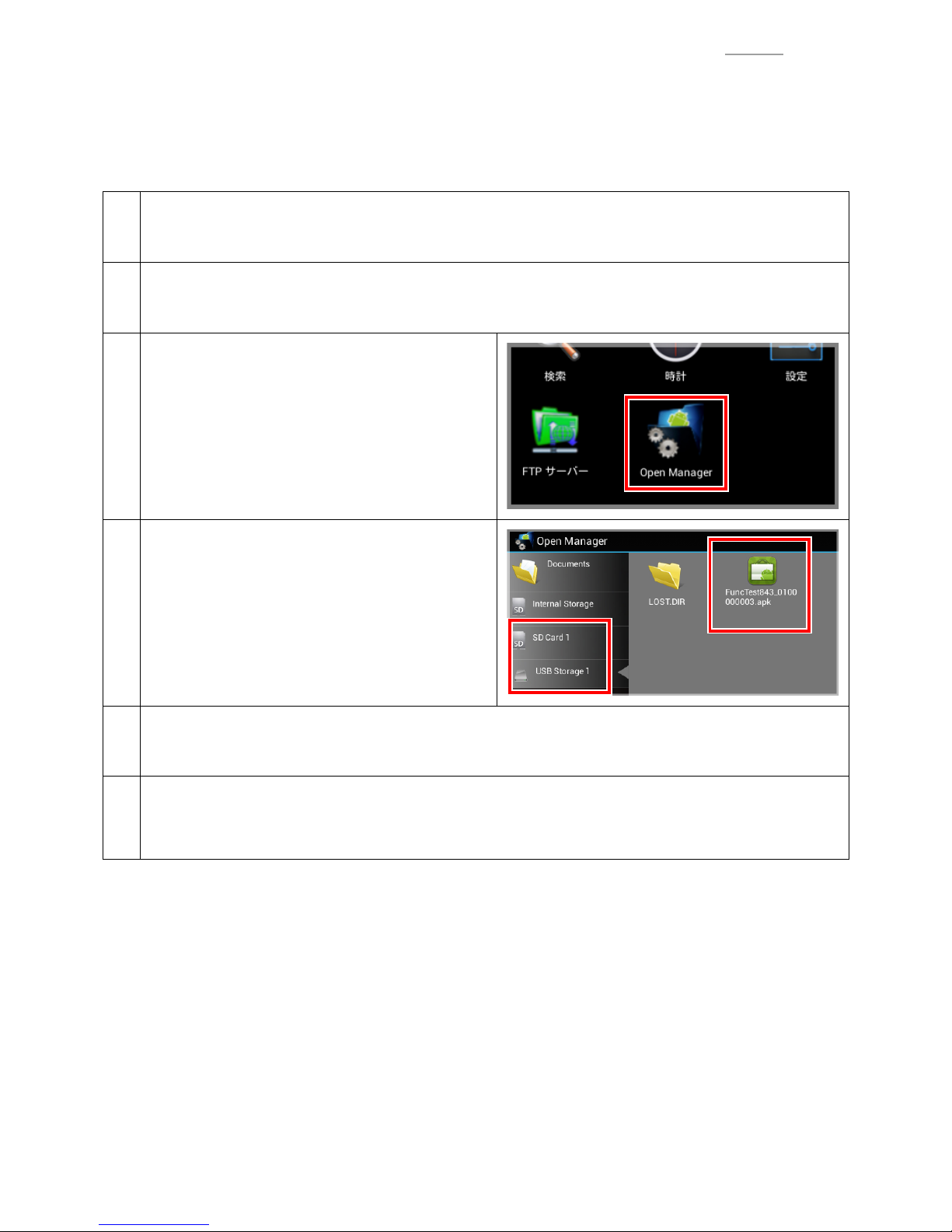
3
Insert a fl
ash memory and tap “Open Manager”.
4
Tap “SD Card 1 OR USB Storage 1” I
“FuncT
est843_0100000003.apk”.
O R
O R
5
T
ap “Next” I “Install”.
After completion of installation, tap either “Done” or “Open”.
6
Remove the fl ash
memory.
Tap “Settings” I “Storage”, unmount the fl
ash memory to allow safe removal, and then remove it.
Page 17

– 15 –
V-R200 / VER.2
1-3.
About the Test Application
The test application runs.
Function Description Refer to
Red frame
Test items
TIPS: “CF Bench” is excluded from the test item.
1-5. Test Method
Set Serial Number
Checking and registering the serial number
TIPS: Carry out when the main PCB is replaced with a
new one.
1-6. Checking and
Registering the Serial
Number
Set MAC Address Not used
SDK Not used
Firmware Update
Updating the fi rmware
TIPS: This item is not used here.
TouchPanel Calibration
Touch panel calibration
TIPS: Carry out this item depending on the situation.
Auto-Run Continuous execution of the test items
Output Result Printing the test results and outputting the result fi le
Settings Launching the Android settings screen
Exit Closing the test application
Test result “OK” Test result “NG”
To interrupt the test item being tested, tap the part indicated by the red frame at the bottom of the screen.
Tap the black belt portion, to display marks.
Page 18
– 16 –
V-R200 / VER.2
1-4. Touch panel calibration
0When the F case “CASE ASSY/FRONT” is replaced with a new one, be sure to carry out the touch panel
calibration.
TIPS: Same operation as Touch Screen Calibration in Settings mode.
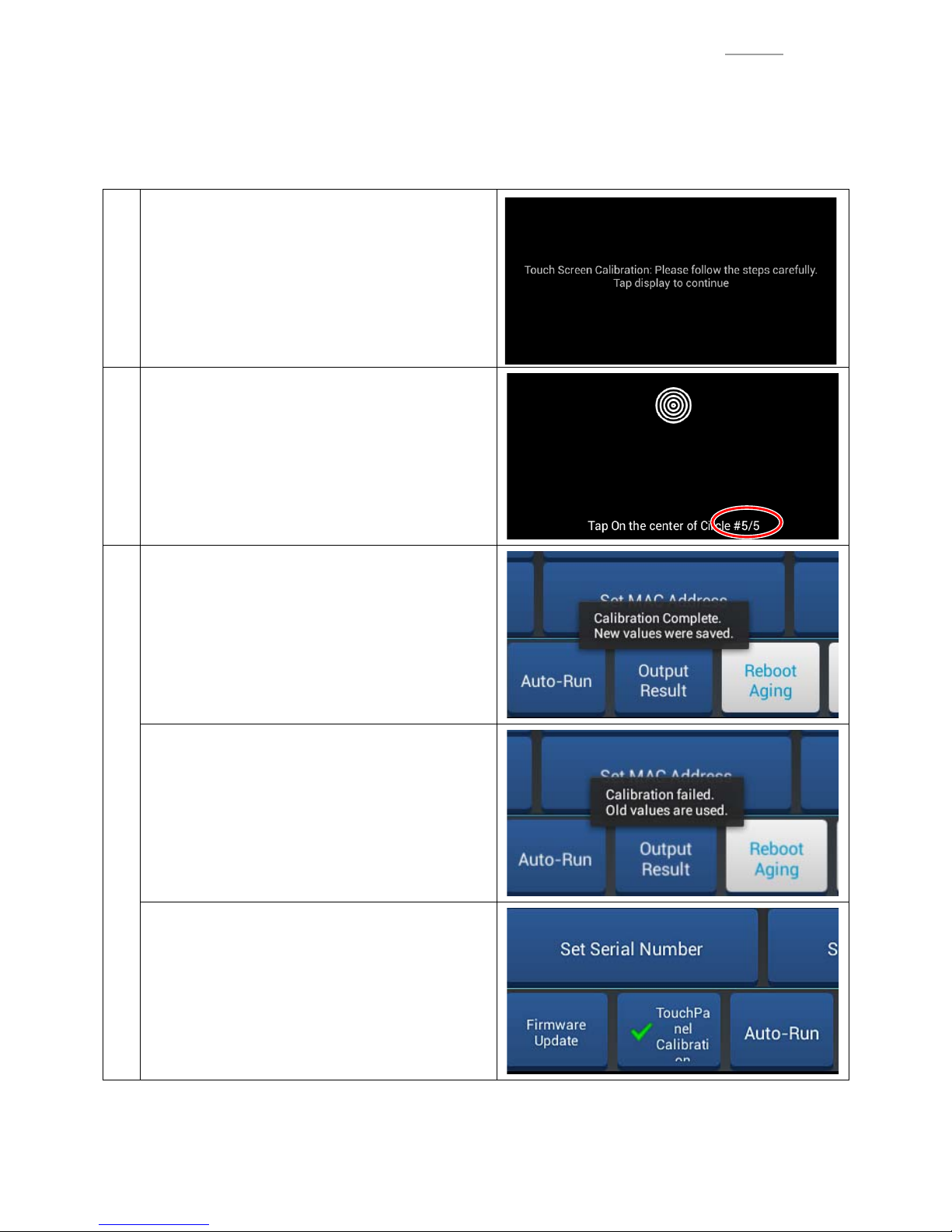
1
Tap “TouchPanel Calibration”.
Tap the screen, following the onscreen instructions.
2
When tapping the last screen (#5/5), the screen
returns to the menu screen.
3
When the calibration ends successfully.
• A success message is displayed for several
seconds.
• The set values are saved.
When the calibration fails.
• A failure message is displayed for several seconds.
• The set values are not saved.
Regardless of the calibration result (either success
or failure), test result “OK” is displayed.
TIPS: When the test result is displayed, the letters
“TouchPanel Calibration” are misaligned.
Page 19
– 17 –
V-R200 / VER.2
1-5.
Test Method
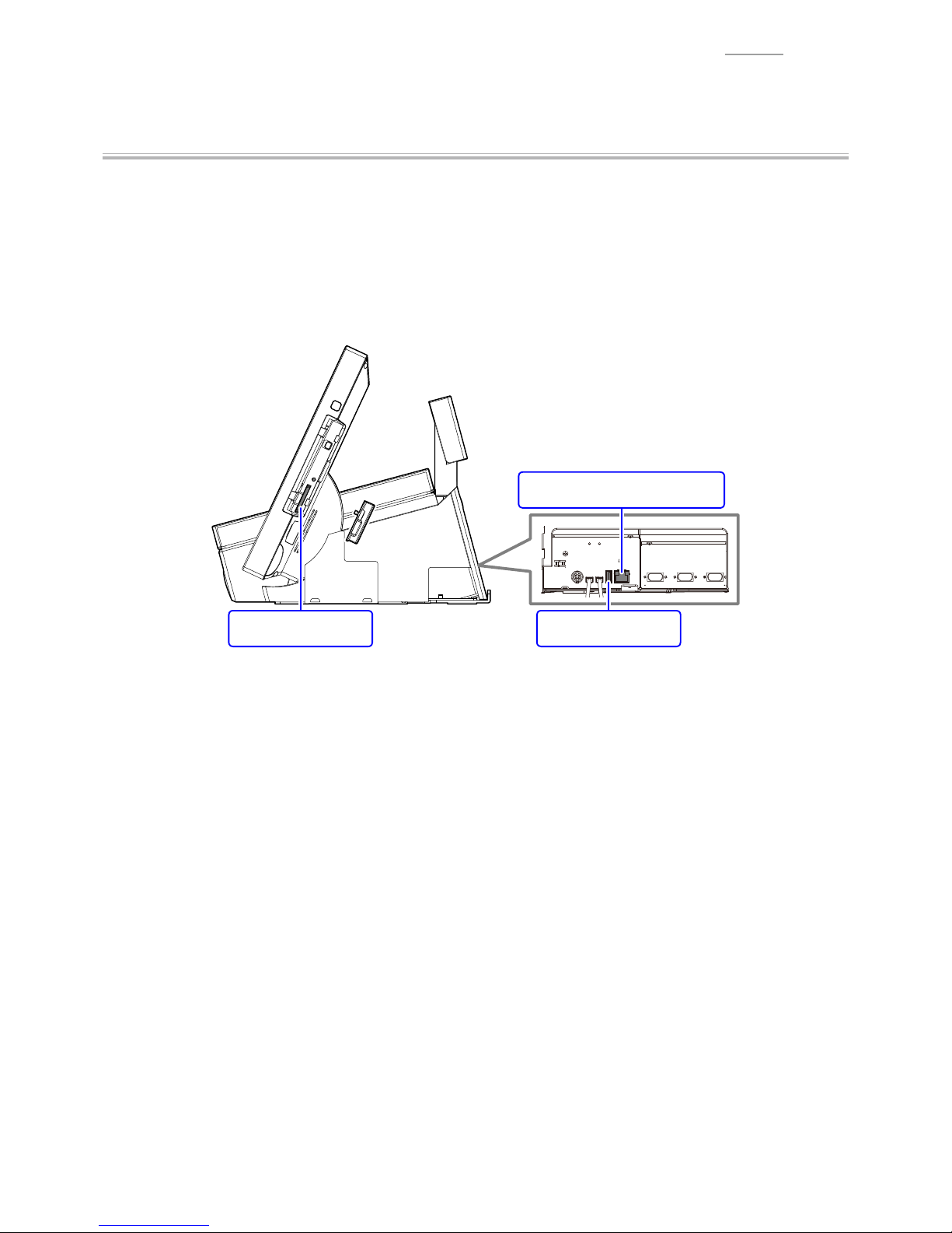
Preparation Before Testing
Prepare the necessary items referring to “1-1. List of test items”.
Before testing, set the following items to the product.
0Set the paper roll.
0Insert the USB memory and SD card.
0Connect the LAN cable (DHCP).
USB memorySD card
For LAN (DHCP) connection
Page 20
– 18 –
V-R200 / VER.2
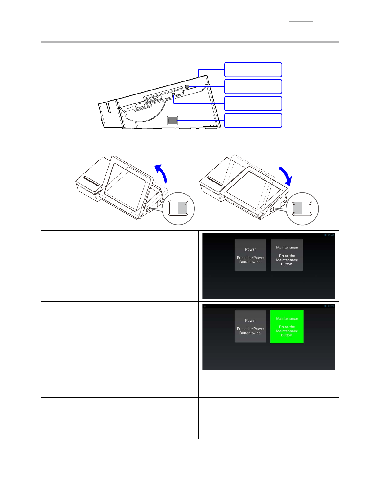
Button
0Test the tilt switch, power switch and maintenance switch.
Power switch
Maintenance switch
Power lamp
Tilt switch
1
Operate the tilt switch to check that the angle of the main display changes accordingly.
TILT
DOWN UP
TILT
DOWN UP
2
Tap “Button” I tap any place on the screen.
3
Press the maintenance switch.
Automatic judgment is done and the test result
appears.
4
Press the power switch. Sleep state
(Screen: Blank, Power lamp: Orange)
5
Tap any place on the screen.
Automatic judgment is done and the test result
appears. Then, the display returns to the menu
screen.
Page 21
– 19 –
V-R200 / VER.2
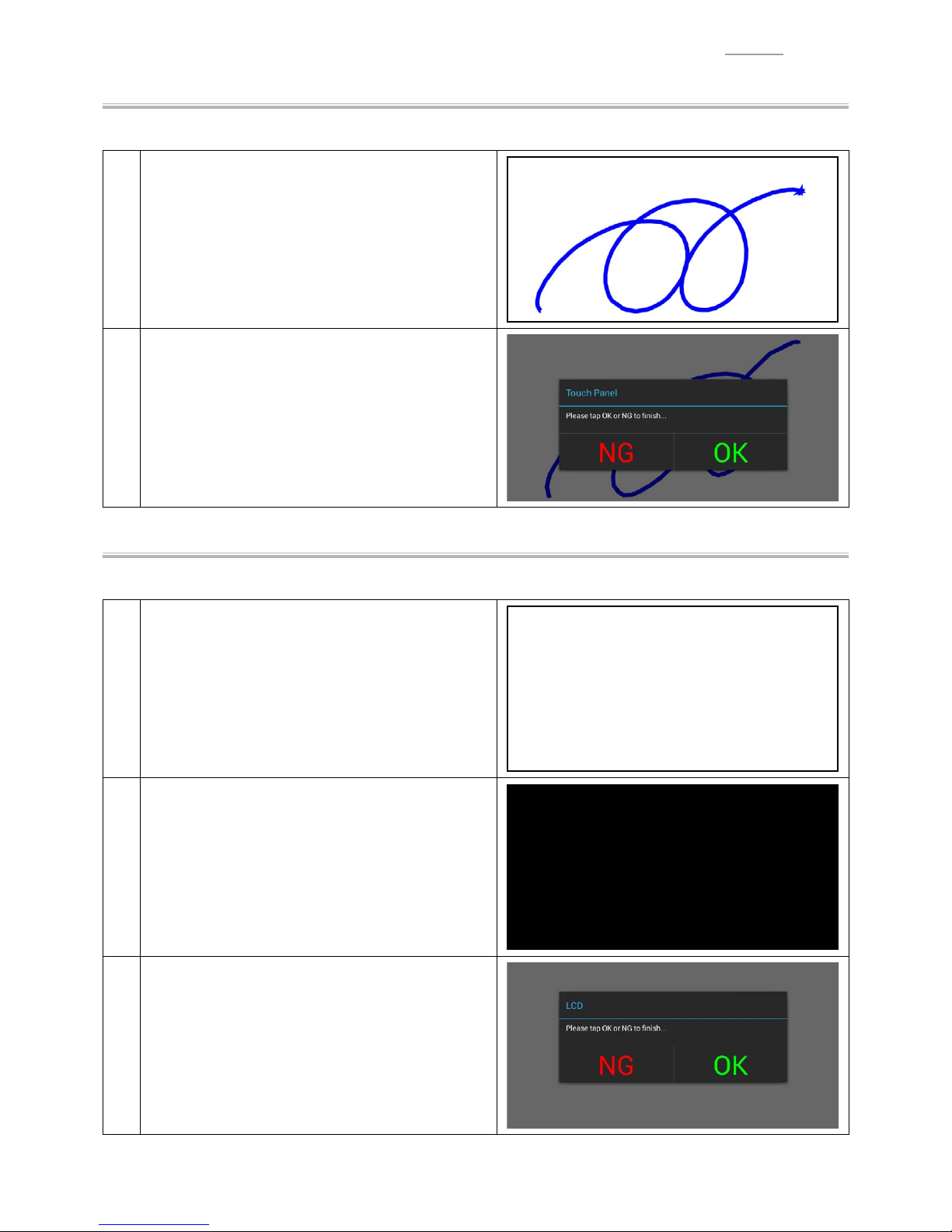
Touch Panel
0Carry out a handwriting test.
1
Tap “Touch Panel” I tap any place on the screen.
Since the screen turns to white, handwrite anything
with your fi nger
tip.
When you lift your fi nger from the screen, the
judgment screen appears.
2
Tap the test result to return to the menu screen.
LCD
0Check that there are no missing dots on the screen.
1
Tap “LCD” I tap any place on the screen.
The screen turns to white.
2
Tap any place on the screen.
The screen turns to black.
3
Tap any place on the screen.
Tap the test result to return to the menu screen.
Page 22
– 20 –
V-R200 / VER.2
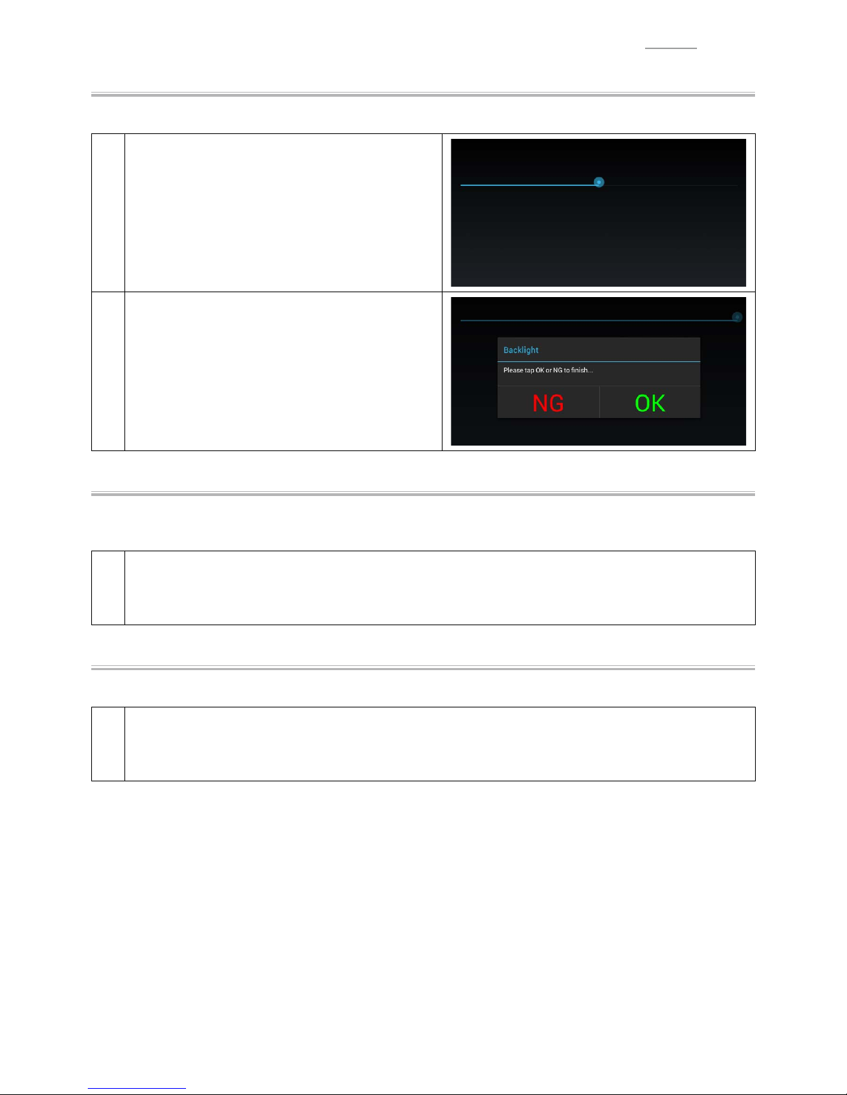
Backlight
0Check that the intensity of the backlight is adjustable.
1
Tap “Backlight” I tap any place on the screen.
Move the slider and check that the brightness of the
screen changes accordingly
.
When you lift your fi nger from the screen, the
judgment screen appears.
2
Tap the test result to return to the menu screen.
USB Storage
0Carry out the USB storage test.
0Make sure that the USB memory is already inserted.
1
Tap “USB Storage”.
Automatic judgment is done and the test result appears on the menu screen.
Internal Storage
0Carry out the Internal storage test.
1
Tap “Internal Storage”.
Automatic judgment is done and the test result appears on the menu screen.
Page 23

– 21 –
V-R200 / VER.2
SD Card
0Carry out the SD card test.
0Make sure that the SD card is already inserted.
1
Tap “SD Card”.
Automatic judgment is done and the test result appears on the menu screen.
Ethernet
0Make sure that the LAN cable (DHCP) is already connected.
0Once success of this test, if you need to test again, perform reboot, then test again.
1
Tap “Ethernet”
Automatic judgment is done and the test result
appears on the menu screen.
NOTE: If LAN cable is not connected or Ethernet
is set to off in Stteings mode, right screen
appears.
MAC Address
0Carry out the MAC address test.
1
Tap “MAC Address”.
Automatic judgment is done and the test result appears on the menu screen.
Page 24

– 22 –
V-R200 / VER.2
COM 1, COM 2, COM 3
0Carry out the COM port communication test.
0Information of the loop back tool.
Pin assignment on the register side (male) Pin Signal name Connection information
51
69
1 DCD
2 RxD
3 TxD
4 DTR
5 GND
6 DSR
7RTS
8 CTS
9RI
1
Connect the loop-back connector to the COM port to be tested.
2
Start the test by tapping the COM port to which the
loop-back connector is connected.
When the test result is “OK”.
3
The COM port tile being tested turns to green, and
COM1: test result appears on menu screen.
COM2&3: judgement screen appears, then tap “OK” to return to menu screen.
When the test result is “NG”.
4
The COM port tile being tested turns to red, and the display returns to the menu screen.
Page 25

– 23 –
V-R200 / VER.2
Dallas Key
0For Dallas key model only
0Carry out the recognition test of Dallas key.
1
Tap “Dallas Key”.
2
Set the Dallas key.
When the Dallas key is recognized normally, the
light green tile appears.
3
Remove the Dallas key.
Another light green tile appears and the display returns to the menu screen.
Page 26

– 24 –
V-R200 / VER.2
Drawer 1, Drawer 2
0DAWER 1: Longer cable, DAWER 2: Shorter cable
Drawer 2
Drawer 1
0The check method and test procedure differ depending on the drawer type.
Model name Check item
Without drawer detecting switch
DL-2814
DL-2822
Drawer opening operation only
With drawer detecting switch
DL-2436
DL-2815
DL-2823
Drawer opening operation and closing operation
1
Tap “Drawer 1” I tap any place on the screen.
For models without drawer detecting switch
2
Tap “Drawer Open”.
The drawer opens, the drawer status is displayed,
and then the judgment screen appears.
TIPS:
Although the tile “Drawer status open” is red, there
is nothing wrong with it.
The test result is “OK” if the tile “Drawer Open”
is green and the opened drawer can be closed
correctly.
Tap “OK” to return to the menu screen.
Page 27

– 25 –
V-R200 / VER.2
For models with drawer detecting switch
3
Tap “Drawer Open”.
The drawer opens and the drawer status is
displayed.
4
Close the drawer.
The drawer status is displayed, and then the
judgment screen appears.
Tap the test result to return to the menu screen.
Page 28

– 26 –
V-R200 / VER.2
MCR
0For MCR model only
0Carry out the magnetic card reading test.
1
Tap “MCR”.
2
Slide the magnetic card for testing.
When the test result is “OK”.
3
When the magnetic card is correctly scanned, a large green circle appears, and then the display
automatically returns to the menu screen.
When the test result is “NG”.
4
Slide the magnetic card for testing again. if the magnetic card is correctly scanned, a large green circle
appears, and then the display automatically returns to the menu screen.
If the test results end up with failure, tap “
” to display the judgment screen.
Tap the test result to return to the menu screen.
Page 29

– 27 –
V-R200 / VER.2
Speaker
0Carry out the speaker output test.
1
Tap “Speaker” I tap any place on the screen.
Check that an alarm sound is heard.
T
ap the test result to return to the menu screen.
Customer Display
0Carry out the sub display test.
1
Tap “Customer Display” I tap any place on the
screen.
Check that the backlight of the sub display changes
in the order of “None (colorless)” → “White” →
“Green” → “Emerald green”.
T
ap the test result to return to the menu screen.
Receipt Printer
0Carry out the character printing, paper feed and paper cutting tests.
1
Tap “Receipt Printer” I tap any place on the
screen.
T
est printing is done and the judgment screen
appears.
Tap the test result to return to the menu screen.
Page 30

– 28 –
V-R200 / VER.2
Auto-Run
0The following items are tested in succession.
Test items Judgment Remarks
Button Auto
Touch Panel Manual
LCD Manual
Backlight Manual
USB Storage Auto To be prepared USB memory
Internal Storage Auto
SD Card Auto To be prepared SD card
CF Bench Skip * Skip this test item as test is not required.
Ethernet Auto To be prepared
LAN cable
* Environment where DHCP connection is available.
Mac Address Auto
COM 1, COM 2, COM 3 Manual To be prepared Loop-back connector
Dallas Key Manual To be prepared Dallas key
Drawer 1, Drawer 2 Manual To be prepared Drawer
MCR Manual To be prepared Magnetic card for testing
Speaker Manual
Customer Display Manual
Receipt Printer Manual To be prepared Paper roll
TIPS: By holding down “Auto-Run” or “Output Result”, you can choose the tests as your requirement.
Page 31

– 29 –
V-R200 / VER.2
1-6.
Checking and Registering the Serial Number
0Carry out check and registration of the product serial number.
1
Tap “Set Serial Number”.
Enter the serial number and tap the “Enter key”.
2
Tap “Set Serial No.”.
3
Tap “
” to display the judgment screen.
Tap the test result to return to the menu screen.
Page 32

– 30 –
V-R200 / VER.2
1-7.
Uninstalling the Test Application
1
Tap “Settings” I “Apps” I “Function Tester”.
2
Tap “Uninstall” I “OK”.
Page 33

– 31 –
V-R200 / VER.2
2.
UPDATING THE OS
2-1. Checking the Version
Select “Settings”
I
“About tablet”, and check the “Build number”.
The OS version is displayed in the following red
rectangular box.
Example:
1.0.0_ 1005
2-2. Updating Method
Preparation
1. Prepare the data with the version you want to update.
Example : V-R200_5059-AAUDAC-ota_update-1.0.0_1011-signed.zip
NOTE : Do not uncompress or change the fi le name.
2. Create a “V-R200Update” folder in the root directory of the SD card, and copy the prepared compressed fi le
to that folder.
Procedure
1. Set the SD card.
2. Tap “Settings”
I
“About tablet”
I
“System Update”.
Page 34

– 32 –
V-R200 / VER.2
3. Confi rm the display content and tap “Execute” twice.
4. After completion of the update, restart begins.
Page 35

V-R200 / VER.1
– 33 –
DISASSEMBLY/ASSEMBLY
YImportant .................................................................................................................... P. 34
YScrews ........................................................................................................................ P. 35
A. Replacing the Main PCB ........................................................................................... P. 36
B. Replacing the LCD Unit ............................................................................................ P. 41
C. Replacing the IOC ASSY ........................................................................................... P. 44
D. Replacing the Sub Display ....................................................................................... P. 47
E. Replacing the Motor .................................................................................................. P. 49
F. Replacing the Printer ................................................................................................ P. 50
G. Replacing the Cable
G-1. IOC PCB - E843-PR PCB ................................................................................... P. 52
G-2. IOC PCB - Main PCB ......................................................................................... P. 55
H. Other Parts
H-1. REAR CASE ....................................................................................................... P. 57
H-2. CASE ASSY/FRONT .......................................................................................... P. 57
H-3. CHASSIS/BOTTOM ............................................................................................ P. 58
H-4. CHASSIS/LCD ................................................................................................... P. 58
Page 36

V-R200 / VER.1
– 34 –
YImportant
• Please note that the product on this manual may appear to be different from the actual one according
to the changes such as engineering design change.
• In order to prevent static electricity and avoid leaving grease from the hand, wear conductive gloves,
fi nger cots, or anti-static band when assembling/disassembling the product.
• Do not use metal tweezers. Be sure to use plastic tweezers with fl at tips.
(Anti-static tweezers are recommended)
• When replacing the MCR, refer to “V-R7000/V-R7100 Installation Manual”.
• The disassembly procedure explained here is based on the model “V-R7100-BD” that is equipped with
Dallas key.
MCR
Dallas key
Page 37

V-R200 / VER.1
– 35 –
YScrews
There are several kinds of screws. Be sure to use the
correct type of screws when reassembling.
It is advisable to sort the screws as shown on the right
after removing them.
S1
( φ : 3mm, L: 10mm)
S2
( φ : 3mm, L: 5mm)
S3
( φ : 3mm, L: 8mm)
10 mm
3 mm
5 mm
3 mm
8 mm
3 mm
S4
( φ : 3mm, L: 8mm)
S5
( φ : 3mm, L: 5mm)
S6B (S6)
( φ : 3mm, L: 8mm)
8 mm
3 mm
5 mm
2 mm
8 mm
3 mm
S7
( φ : 3mm, L: 8mm)
S8
( φ : 2.5mm, L: 6.2mm)
S9
( φ : 2mm, L: 6mm)
8 mm
3 mm
6.2 mm
2.5 mm
6 mm
2 mm
S10
( φ : 3mm, L: 10mm)
10 mm
3 mm
Page 38

V-R200 / VER.1
– 36 –
A. Replacing the Main PCB
Supplementary explanation
When the main PCB is replaced with a spare part one.
• Since an OS is already installed on the spare part main PCB, update the OS to an appropriate
version as required.
Refer to: Diagnostic operation
2. UPDATING the OS
• Write the serial number.
Refer to: Diagnostic operation
1-6. Checking and Registering the Serial Number
A-1. Removal of the DISPLAY-ASSY
(1) Undo two screws.
Screw (S1)
(2) Remove the DISPLAY-ASSY.
Page 39

V-R200 / VER.1
– 37 –
(3) Remove one cable tie.
(4) Undo one screw and remove two ground wires.
(5) Disconnect three connectors. (Four connectors for the model “V-R200-BD” (Dallas key built in model)).
Connector 3
Screw (S2) Ground wire 2Cable tie
Connector 1
V-R200-BD (Dallas key built in model) only
Note on reassembling
0Put the lead wires of the speaker in the case.
A-2. Remove the following parts.
(1) COVER/SHEET (Screw (S8) 1)
(2) COVER/BATTERY (Screw (S3)
2)
(3) COVER/CONNECTOR (COVER-USB)
(4) COVER/SD (Screw (S8)
1)
(3)
(COVER/USB)
(4)
COVER/SD (S8)
(1)
COVER/SHEET (S8)
(2)
COVER/BATTERY (S3)
(3)
COVER/CONNECTOR
Page 40

V-R200 / VER.1
– 38 –
A-3. Undo fi ve screws and remove the REAR CASE.
Screw (S6) 5
REAR CASE
H-1
Note on reassembling
0Assemble the REAR CASE in the order indicated by the numbers below.
1
2
3
4
Page 41

V-R200 / VER.1
– 39 –
A-4. Undo four screws and remove the CHASSIS/HNG.
Screw (S2) 4
CHASSIS/HNG
Note on reassembling
0Fix the lead wires of the battery with tape.
Tape
Note on reassembling
V-R200-BD (Dallas key built in model)
0Fix the ferrite core with double-sided tape, and then fi x its lead wires and the lead wires of the battery together
with tape.
CUSHION/DLS Tape
Page 42

V-R200 / VER.1
– 40 –
A-5. Removal of the main PCB (PCB ASSY/E843-1)
(1) Unlock the connector lock and disconnect the FPC.
(2) Disconnect four connectors.
(3) Undo four screws.
(4) Replace the main PCB (PCB ASSY/E843-1) with a new one.
(1) FPC
(2) Connectors
(2) Connector
Ground wire
(3) Screw (S2) 4
(4)
PCB ASSY/E843-1
Note on reassembling
0In this stage, the two places shown below are not fastened with screws yet.
A-6. Assemble the parts in the reverse order of the disassembly procedure.
Page 43

V-R200 / VER.1
– 41 –
B. Replacing the LCD Unit
Supplementary explanation
When the CASE ASSY/FRONT is replaced with a spare part one.
• Carry out the touch panel calibration.
Refer to: Diagnostic operation
1-4. Touch panel calibration
Model with no Dallas key
B-1. Remove the REAR CASE.
Reference Procedure: A-1 to A-3
B-2. Removal of the CHASSIS/LCD
(4) Screw (S4) 5
(3) Connector
(1) Tape (
15 50)
(1) Tape (
15 50)
NOTE: There is a connector under the tape. Peel
off the tape without giving a load to the
connector.
(3) Connectors
(1) Tape (
15 30)
NOTE: Peel off the tape without giving a load to
the FPC.
(2) FPC
(1) Peel off tape (3 pcs.).
(2) Unlock the connector lock and disconnect the FPC.
(3) Disconnect three connectors.
(4) Undo fi ve screws.
(5) Remove the CHASSIS/LCD block.
(5) CHASSIS/LCD
block
Note on reassembling
Ground wire
When attaching the ground wire, make sure that the
wire does not protrude from the CHASSIS/LCD.
Page 44

V-R200 / VER.1
– 42 –
Dallas key built in model
B-1. Remove the CHASSIS/HNG.
Reference Procedure: A-1 to A-4
B-2. Remove the CHASSIS/LCD.
(1) Peel off tape (3 pcs.).
(2) Unlock the connector lock and disconnect the FPC.
(3) Disconnect three connectors.
(4) Peel off the tape that is fi xing the lead wires from the Dallas key.
(5) Remove the Dallas key’s ferrite core that is fi xed with double-sided tape.
(6) Undo fi ve screws.
(7) Remove the CHASSIS/LCD block.
(6) Screw (S4) 5
(1) Tape (
15 50)
NOTE: There is a connector under the tape. Peel
off the tape without giving a load to the
connector.
(3) Connector
(1) Tape (
15 30)
NOTE: Peel off the tape without giving a load to
the FPC.
(7) CHASSIS/LCD
block
(3) Connector
(2) FPC
(1)
Tape (
15 50)
(4) Tape(5) Ferrite core
Note on reassembling
Ground wire
When attaching the ground wire, make sure that the
wire does not protrude from the CHASSIS/LCD.
Page 45

V-R200 / VER.1
– 43 –
B-3. Remove the LCD unit (LCD UNIT).
CASE ASSY/FRONT
H-3
LCD UNIT
Note on reassembling
0Attach the four cushions to the new LCD UNIT.
NOTE: Attach them in the order indicated by the numbers below.
1
2
3 4
CUSHION/LCD
1234
0Make sure that no dirt or dust is on the touch panel surface and LCD surface.
B-4. Assemble the parts in the reverse order of the disassembly procedure.
Page 46

V-R200 / VER.1
– 44 –
C. Replacing the IOC ASSY
Supplementary explanation
When the IOC PCB is replaced with a spare part one.
• Firmware is already installed on it.
• The fi rmware version is confi rmed at power on and, if necessary, it is automatically updated.
• UUID setting is not required.
C-1. Undo 11 screws and remove the CHASSIS/BOTTOM.
NOTE: There are two types of screws (S2 × 6, S7 × 4).
Screw (S2) 7
Screw (S7) 4
CHASSIS/BOTTOM
H-4
Page 47

V-R200 / VER.1
– 45 –
C-2. Remove the following parts.
(1) Connector 4 (Model with no Dallas key)
Connector 5 (Dallas key built in model)
(2) Printer FFC
(3) Tape, Ferrite core, Sub Display FFC
(4) Scrwe
12
NOTE: There are two types of screws (S2 × 8, S7 × 4).
(3) Tape, Ferrite core, Sub Display FFC
• Tape (15
50)
NOTE: Peel off the tape without giving a load to the FFC
and connector.
(1) Connector 4(2) Printer FFC
Screw (S2) 8
Screw (S7) 4
(1) Connector 1
V-R200-BD (Dallas key built in model) only
Ground wire 2
C-3. Remove the IOC ASSY.
C-4. Disconnect the connectors.
IOC ASSY
Connector
Page 48

V-R200 / VER.1
– 46 –
C-5. Remove the following parts.
(1) Cable tie 1
(2) Scrwe
1
(3) Cable
2
C-6. Replace the IOC ASSY with a new one.
IOC ASSY
(1) Cable tie
(3) CABLE/DRW1
(3) CABLE/DRW2
(2) Screw + Ground wire
Note on reassembling
0Drawer cables
DRW1 Connector
• DRW1-CABLE-SUBASSY (Longer cable)
• Earth terminal fastening screw (S2)
• Tie the cables with a cable tie.
DRW2 Connector
• DRW2-CABLE-SUBASSY
(Shorter cable)
C-7. Assemble the parts in the reverse order of the disassembly procedure.
Page 49

V-R200 / VER.1
– 47 –
D. Replacing the Sub Display
D-1. Remove the CHASSIS/BOTTOM.
Reference Procedure: C-1
D-2. Peel off tape (2 pcs.) and disconnect the FFC.
CLOTH-TEPE (10 30)
CLOTH-TEPE (15 50)
NOTE: Peel off the tape without giving a load to the connector.
Ferrite core
FFC
D-3. Release hooks and remove the sub display (DISPLAY ASSY/REAR).
DISPLAY ASSY/REAR
Hooks
Note on replacing
0Form the FFC into shape by using the following jig.
3
33 mm
29 mm
22 mm
Page 50

V-R200 / VER.1
– 48 –
12
34
5
D-4. Assemble the parts in the reverse order of the disassembly procedure.
Page 51

V-R200 / VER.1
– 49 –
E. Replacing the Motor
E-1. Remove the IOC ASSY.
Reference Procedure: C-1 to C-3
E-2. Undo two screws and remove the MOTOR SUPPORT.
E-3. Undo two screws and replace the motor (GEAR ASSY) with a new one.
MOTOR SUPPORT
GEAR ASSY
Screw (S11) 2 Screw (S4) 2
E-4. Assemble the parts in the reverse order of the disassembly procedure.
Page 52

V-R200 / VER.1
– 50 –
F. Replacing the Printer
F-1. Undo two screws and remove the PLATE/BLIND.
Screw (S7) 2
PLATE/BLIND
F-2. Unlock the connector lock and disconnect two FPCs.
FPC
F-3. Remove the SHEET/BLIND.
NOTE: Be careful not to put a scratch on the MASK/PRINTER, when removing the SHEET/BLIND.
F-4. Undo two screws and remove the PLATE/BLIND.
MASK/PRINTER
Screw (S4) 2
SHEET/BLIND
Page 53

V-R200 / VER.1
– 51 –
F-5. Undo two screws and remove the PRINTER.
PRINTER
Screw (S5) 2
F-6. Undo two screws and remove the PLATEN.
PLATEN
Screw (S2) 2
F-7. Assemble the parts in the reverse order of the disassembly procedure.
Page 54

V-R200 / VER.1
– 52 –
G. Replacing the Cable
G-1. IOC PCB - E843-PR PCB
FFC-JOINER-E840PR
Note on replacing
0Form the FFC into shape by using the following jigs.
1
33 mm
13 mm
33 mm
2
33 mm
19 mm
48 mm
79 mm
3
33 mm
29 mm
22 mm
Page 55

V-R200 / VER.1
– 53 –
12
34
5
8 mm
67
89
Page 56

V-R200 / VER.1
– 54 –
10
11 1 2
13
Page 57

V-R200 / VER.1
– 55 –
G-2. IOC PCB - Main PCB
0Remove the IOC ASSY. 0Remove the DISPLAY-ASSY.
Reference Procedure: C-1 to C-3 Reference Procedure: A-1
Ferrite core
0Remove the ferrite core.
0Remove the CABLE MASK.
0Replace the cables.
FG-CABLE-SUBASSY
IOC-CABLE-SUBASSY
CABLE MASK
USB-CABLE-SUBASSY
Page 58

V-R200 / VER.1
– 56 –
Note on replacing
0Bundle the three or four cables with tube.
175 ± 5 mm
110 ± 5 mm
130 ± 5 mm
80 ± 5 mm
CABLE-SUBASSY/IOC
CABLE-SUBASSY/USB
CABLE-SUBASSY/DASR
* V-R200-BD only
CABLE-SUBASSY/FG
Connector (female)Connector (male)
Tube (70mm, 10 mm)
Note on reassembling
0Fix the cables with tape.
FILAMENT-TEPE (15 40)
NOTE: Align the border between black and white of the
USB-CABLE-SUBASSY with the boss.
NOTE: Fold back the lead wires of the motor at the rib.
Page 59

V-R200 / VER.1
– 57 –
H. Other Parts
Supplementary explanation
• For the parts other than the replaced parts, reuse the original ones.
H-1. REAR CASE BLOCK
SPEAKER
Screw (S7) 2
Screw (S6)
CASE/REAR
COVER/BOOT
BLIND/DALLAS
Screw (S9) 2
H-2. CASE ASSY/FRONT
LENS/LED
Screw (S10) 3
PCB ASSY/E843-E61
CASE ASSY/FRONT
Page 60

V-R200 / VER.1
– 58 –
H-3. CHASSIS/BOTTOM
PAD/RUBBER/E843
PAD/RUBBER 3
BLIND/CN
CHASSIS/BOTTOM
H-4. CHASSIS/LCD
BATTERY-ASSY 3
BOX/BAT
SHEET/BAT
CHASSIS/LCD
Page 61

V-R200 / VER.1
– 59 –
CIRCUIT DIAGRAM
YBlock Diagram
SD Card
Slot
Power
Switch
E843-PR
Feed Motor
Thermal Printer Unit
RJ45
E843-E63
Rear LCD
160x32 Full dots
10.4 inch
Touch Panel
10.4 inch TFT-LCD
AC 100-240 V
E843-IOC
Tilt
Motor
MCR*
COM1
Off
Switch
Reset
Switch
USB
Hub
LVDS
CPU DDR
TP
Control
Charger
eMMC
NAND
Debag
10-pin
USB
Client
Power
USB
PHY
PMIC
E843-E61
E843-1
Status
LED
LED
Battery × 3
Speaker
Dallas
Key
Power
USB-A
E843-E22
COM2
COM3
Tilt
Switch
(Up)
Tilt
Switch
(Down)
AC Adaptor
Drawer*
Drawer*
* Optional
* Optional
IOCLAN
ETH
Cutter Motor
CN14
(3 pin)
CN11
(10 pin)
CN8
(10 pin)
CN1
(2 pin)
CN7
(3 pin)
CN6
(2 pin)
CN2
(8 pin)
CN15
(4 pin)
CN3
(9 pin)
CN18
(32 pin)
CN502
(2 pin)
CN13
(4 pin)
CN6
(6 pin)
CN2
(20 pin)
CN3
(4 pin)
CN5
(5 pin)
CN9
(2 pin)
Page 62

V-R200 / VER.1
– 60 –
YPCB
E843-1 PCB
0.3TH
Thermal Via
123
456
12
43
123
456
12
43
1(G)
2(S)
3(D)
1(G)
2(S)
3(D)
IG
O
1(G)
2(S)
3(D)
212121
21
23456
1
12
Top entry
Top entry
12
312
12
12
12
43214321432143
21
43
21
IG
O
12123456 7811019
13
15
1617
14
65
60
18
19
30
3148
49
707172
73
6667 68
69
62
64
65
63
61
1
C20
IC20
R219
IC26
C33
C34
C35
C36
R222
IC31
R225
IC32
R226
IC34
R228
R229
IC38
R232
P100
R234
C48
IC40
P101
C49
P102P103
P104P105P106P107
C50
C200
P108
C51
C201
P109
C53
C205
C55
C206
C56
C57
P110
C58
C59
P111P112P113
P114
P115
P116
P117
C60
P118
C61
P119
C62
C63
Q10
C64
Q11
C65
Q12
C66
C67
C217
Q14
C218
P120
C68
Q15
C219
P121
C69
P122P123
Q18
P124
Q19
C220
P128
C70
C221
P129
C71
C222
C72
C73
C224
C74
C75
C225
C76
C77
C227
C78
C228
P130
C79
C229
P131
P132
P133
P134
P135
P136
P137
C80
C230
P138
C81
P139
C82
C232
C83
C84
C85
C86
C87
C88
P140
C89
P141
P142
P143
P144
R278
R279
P147
P148
C91
C92
C93
R280
R282
R283
R284
P150
P151
R285
R286
P153
R289
R290
R291
R295
D3D4D5
R299
D6
ZZZ1
C279
ZZZ2
ZZZ3
ZZZ4 ZZZ5
ZZZ6
C282
C283
C284
C285
C286
SW1
SW2 SW3
C291
C294
C296
C298
TH1
R101
CN11
R102
R103
CN13
R104
CN14
R105
R106 R107
R108
R109
D12 D14
R302
R110
D18
R111
D19
R305
R112
R306
R113
R308
R114
R115
R116
R117
D20
R119
D21
D25
R120
L2L3L4L5L6
R126
R127
L7
L8L9
R132
R137
L10
L12
C100
L16
C103C104
C107
R144
C109
R145
R146
C300
C302
C303
L23
C110
C304
IC2
C112
C307
P10
C308
C115
P11
C309
C116
IC6
P12
C117
P13
C118
P14
C119
P15
R155
P16 P17P18
C310
P19
C311
C312C313
C120
R10
C121
R11
C316
C122
R12
C317
C123
R13
C124
R14
P20
P1
R15
P21
FU1
P22
P2
R16
P23
C127
P3
P24
C128
P4
P25
C129
P5
R19
P6
P26
P7
P27
R167
P28
P8
R168
P29
P9
R169
C322
R20
C130
R21
C131 C132
R22
R23
P30
C134
R24
R170
P31
Q1
R25
R171
C136
P32
Q2
R26
R172
R27
P33
C137
R173
C138
R28
P34
R174
R29
P35
C139
R175
P36
R176
P37
R177
P38
R178
P39
R179
C140
R31
C142
P40
R180
P41
R181
P42
R182
P43
R183
P44
R184
R5
P45
R185
P46
R6
R186
R7
P47
R8
P48
R9
P49
C152
C153
P50
C154
R190
P51
C155
R191
P52
C156
P53
R47
C157
P54
R48
R49
P55
P56P57
P58
R52
R53
P68
P69
R60
P70
P71
P72
P73
P74
R68
P75
R69
P76P77P78P79
R71
R72
R73
P80
P81
R76
P82
R77
P83
R78
P84
R79
P85P86P87
P88P89
R80
R81
R82
R83
R84
P90
R85
P91
R86
P92
R87
P93
C197
R88
P94
C198
R89
P95
C199
P96
P97
P98
CN1
P99
CN2
CN3
5NC4NC
R91
CN6
R92
CN7
R93
CN8
R94
CN9
C11
C12
C13
C14
C15
C16
IC10
IC11
IC12 IC13
IC14
CN11
CN13
CN14
+
CN1
CN2
CN3
CN4
CN5
CN6
CN7
CN8
CN9
E843-1
C
G
12
43
123
456
8765
1234
1(G)
2(S)
3(D)
1(G)
2(S)
3(D)
3
12
IG
O
IG
O
IG
O
21
21
21
12
12
12
12
58
145814
5
8
14
5
8
14
581458
14
58
14
8765
1234
IG
O
IG
O
IG
O
1(G)
2(S)
3(D)
IG
O
1(G)
2(S)
3(D)
1
43
2
43
12
IC18
IC19
C21
C22
C23
C24
R210
C25
C26
R212R213
C27
C28
C29
R215
IC21
R216
R217
IC23
IC24
IC25
IC27
C30
IC28
C31
IC29
C32
R220
R221
R223
C37
R224
IC30
C38
C39
R227
IC35
IC36
IC37
C40
C41
C42
C43
C44
R230
C45
R231
C46
R233
C47
IC41
R235
IC42
R236
R237
R238
R239
C52
C202
C203
C54
C204
R241
R242
C207
R243
C208
R244
C209
R245R246
R247R248
R249
C210
C212
C213
C214
R250
C215
R251
C216
R252
Q13
R253
R254
R255
Q16
R256
Q17
R257
R258
R259
C223
R260
Q20
R261
Q21
Q22
C226
R262
R263
R264
R265
R266
R267
R268
C231
C233
C234
R270
C235
R271
C236
C237
R273
C238
R274
C239
P145
C90
C240
C241
C242
C243
C244
C94
C245
C95
C246
C96
C97
C247
C98
C248
C1
C99
C249
C2
C3
C4
C5
C6
C7
C8
C250
C9
C251
C252
C253
C254
C255
C256
R292
C257
R293
C258
R294
D1
C259
D2
R296
R297
R298
D7
D8
C260
D9
C261
C262
C263
C264
C265
C266
C267
C268
C269
C270
C271
C272
C273
C274
C275
C276
C277
C278
ZZZ7
C292
C293
C295
C297
C299
R100
CN10
CN12
D10
D11
D13
R300
D15
R301
D16
D17
R303
R307
R309
R118
D22
D23
D24
R121
L1
R122
R123
R124
R125
R128
R129
RM1 RM2RM3 RM4
RM5 RM6
RM7
R130
R131
R133
R134
R135
R136
R138
L11
R139
L13
L14
C101
L15
C102
L17
R140
L18
R141
C105
L19
R142
C106
R143
C108
L20
R148
C301
L21
R149
L22
C111
IC1
C305 C306
C113
IC3
IC4
C114
R150
R151
R152
IC7
R153
IC8
R154
IC9
R156
R157
R158
R159
C314C315
C318
R160
C319
C125
R161
C126
R162
R17
R163
R18
R164
R165
R166
C320
C321
C133
C135
Q3 Q4
Q5
Q6
Q7
Q8
R30
C141
R32
R33
C143
C144
R34
R35
R1
C145
R2
R36
C146
C147
R3
R37
C148
R4
R38
C149
R39
R187
R188
R189
R40
C150
C151
R41
R42
R43
R44
R45
R46
R192
R193
C158
R194
C159
R195
R196
R197
R198
R50
C160
R51
C161
C162
C163
C164
C165
R56
C166
R57
C167
R58
C168
R59
C169
C170
R61
C171
R62
C172
R63
C173
R64
C174
R65
C175
R66
C176
R67
C177
C178
C179
R70
C180
C181
C182
C183
C184
C185
C186
C187
C188
C190
C191
C192
C193
C194
C195
C196
R90
X1
R95
R96
X2
R97
R98
R99
C10
R200
R201
R202
R203
C17
R204
C18
R205
C19
R206
R208
IC15
R209
IC16
IC17
Page 63

V-R200 / VER.1
– 61 –
E843-IOC PCB
E843-PR PCB
Page 64

V-R200 / VER.1
– 62 –
E843-E22 PCB
E843-E61 PCB
E843-E63 PCB
Page 65

– 63 –
V-R200 / VER.2
EXPLODED VIEW/PARTS LIST
MODEL : V-R200
(EX-843)
1.
MAIN UNIT ......................................................................................................... P.64
2.
DISPLAY-ASSY.................................................................................................. P.66
3.
CABLES ............................................................................................................. P.68
4.
ACCESSORIES ................................................................................................. P.70
NOTES :
1. Price and specifi cations are subject to change without prior notice.
2. As for spare parts order and supply, refer to the “GUIDEBOOK for Spare Parts Supply”, published
separately.
3. The numbers in item column correspond to the same numbers in drawing.
4. CASIO does not supply the spare parts without parts code.
5. Refer to the latest “Parts Price Code” at “PARTS FINDER” on the Casio Service WEB site
(https://www.servicecasio.com).
6. Remarks
Q’ty: Quantity used per unit
RANK: A = Essential
B = Stock recommended
C = Less recommended
X = No stock recommended
7. We recommend to purchase screws locally.
e.g. SCREW (38)
Diameter: 3 mm, Length: 8 mm
NUT (4X0.7)
Diameter:4 mm, Thickness: 0.7 mm
Page 66

– 64 –
V-R200 / VER.2
1.
MAIN UNIT
EXPLODED VIEW
5
S5
1214
13
3
S4
S2
4
1-5
1-6
1-1
1-4
1-2
1-3
6
10
7
S2
S1
DISPLAY-ASSY
2
1
S10
S4
S2
8
9
11
S2
Page 67

– 65 –
V-R200 / VER.2
PARTS LIST
1: V-R200-BD 2: V-R200-BD-WE 3: V-R200-U 4: V-R200-U-WE 5: V-R200-C
12345
MAIN UNIT
N 1 10540722 CASE ASSY/UPPER/BK RJE504576*001V01 1 1 1 C
N 1 10540723 CASE ASSY/UPPER/WE RJE504576*002V01 1 1 C
S1
SCREW (3x10) S-PADSMA-3X10Z3 22222X
N 1-1 10540717 COVER/PRINTER/BK RJE504693*001V01 1 1 1 C
N 1-1 10540718 COVER/PRINTER/WE RJE504693*002V01 1 1 C
N 1-2 10529377 ARM/PLATEN RJE504567-001V01 11111C
N 1-3 10465445 LEVER/EJECT RJE504177-001V01 11111C
N 1-4 10540724 LABEL/PUSH RJE503907-003V01 11111X
N 1-5 10529371 MASK/PRINTER RJE504584-001V01 11111C
S4
SCREW (3x8) S-BDPT-3X8Z3 22222X
1-6 10413753 GEAR ASSY TK-RJE503868*001 11111B
S4
SCREW (3x8) S-BDPT-3X8Z3 22222X
S10
SCREW (3x10) S-BDPT-3X10Z3 22222X
N 2 10525695 PRINTER/THERMAL CAPD347J-E 11111Awith Cutter
S2
SCREW (3x5) S-BDMA-3X5Z3 22222X
S5
SCREW (2x5) S-PAMA-2X5Z3 22222X
N 3 10525699 SHEET/BLIND RJE504607-001V01 22222A
N 4 10540719 DISPLAY ASSY/REAR/BK RJE504575*001V01 1 1 1 C
N 4 10540720 DISPLAY ASSY/REAR/WE RJE504575*002V01 1 1 C
N 5 10529378 COVER/IF/BK RJE504555-001V01 1 1 1 X
N 5 10529379 COVER/IF/WE RJE504555-002V01 1 1 X
S2
SCREW (3x5) S-BDMA-3X5Z3 11111X
6 10406965 SW SUBASSY/TILT RJE503884*001V01 1 1 1 B
6 10436482 SW SUBASSY/TILT RJE503884*002V01 1 1 B
N 7 10540726 PCB ASSY/E843-E63 RJE504582*001V01 11111B
N 8 10540725 PCB ASSY/E843-PR RJE504579*001V01 11111B
S2
SCREW (3x5) S-BDMA-3X5Z3 11111X
N 9 10540721
PCB ASSY/E843-IOC
W/CHASSIS
RJE504692*001V01 11111A
S2
SCREW (3x5) S-BDMA-3X5Z3 88888X
S7
SCREW (3x8) S-BD-PT-3X8Z3 44444X
N 10 10529382 CHASSIS/BOTTOM RJE504541-001V01 11111X
S2
SCREW (3x5) S-BDMA3X5-Z3 77777X
S7
SCREW (3x8) S-BD-PT-3X8Z3 44444X
N 11 10529384 PLATE/BLIND RJE504583-001V01 11111X
S7
SCREW (3x8) S-BD-PT-3X8Z3 22222X
12 10414065 PAD/RUBBER RJE503879-001V02 33333X
N 13 10540737 PAD/RUBBER/E843 RJE504592-001V03 11111X
14 10413634 BLIND/CN RJE503920-001V01 11111X
R RemarksN Item Code No. Parts Name Specification
Qt'y
Page 68

– 66 –
V-R200 / VER.2
2.
DISPLAY-ASSY
EXPLODED VIEW
Screws
16
22
21
25
20
26
24
23
33
18
34
29
17
d
30
32
35
S3
S9
S7
S8
S8
31
27
S6
29
S9
39
19
c
a
b
bd c a
Dallas key model
Dallas key model
Dallas key model
37
38
36
15
Dallas key model
Page 69

– 67 –
V-R200 / VER.2
PARTS LIST
1: V-R200-BD 2: V-R200-BD-WE 3: V-R200-U 4: V-R200-U-WE 5: V-R200-C
12345
R RemarksN Item Code No. Parts Name Specification
Qt'y
DISPLAY-ASSY
N 15 10537626 CASE ASSY/FRONT/BK RJE504694*001 TK 1 1 A Including Touch Panel
N 15 10537627 CASE ASSY/FRONT/WE RJE504694*002 TK 1 A Including Touch Panel
N 15 10537628 CASE ASSY/FRONT/BK/DLS RJE504694*003 TK 1 A Including Touch Panel
N 15 10537629 CASE ASSY/FRONT/WE/DLS RJE504694*004 TK 1 A Including Touch Panel
16 10416295 LENS/LED RJE503847-001V02 11111C
N 17 10540727 PCB ASSY/E843-E61 RJE504581*001V01 11111B
S9
SCREW (2x6) S-BDPT-2X6Z3 33333X
N 18 10517415 LCD UNIT G104STN01.0 11111A
N 19 10544514 CUSHION/LCD RJE504664-001V01 11111A
N 20 10529356 CHASSIS/LCD RJE504536-001V01 11111X
S4
SCREW (3x8) S-BDPT-3X8Z3 55555X
21 10409528 BOX/BAT RJE503893*001V01 11111C
22 10409546 SHEET/BAT RJE503903-001V01 11111X
N 23 10540716 PCB ASSY/E843-1 RJE504603*001 TK 11111A
S2
SCREW (3x5) S-BDMA-3X5Z3 55555X
N 24 10529357 CHASSIS/HNG RJE504535-001V01 11111X
S2
SCREW (3x5) S-BDMA-3X5Z3 44444X
25 10413757 BATTERY-ASSY TK-RJE503905*001 33333B
N 26 10530397 CASE/REAR/BK RJE503837-003V04 1 1 1 X
S6B
SCREW (3x8) S-BDPT-3X8B3 5 5 5 X
N 26 10540735 CASE/REAR/WE RJE503837-004V04 1 1 X
S6
SCREW (3x8) S-BDPT-3X8NI 5 5 X
27 10409533 BLIND/DALLAS/BK RJE503838-003V01 1 1 X
27 10436469 BLIND/DALLAS/WE RJE503838-004V01 1 X
27 10409514 COVER/DALLAS/BK RJE503839-001V01 1 X
27 10476663 COVER/DALLAS/WE RJE503839-002V01 1 X
N 28 10540728 COVER/SHEET/BK RJE503841-003V02 1 1 1 C
N 28 10540729 COVER/SHEET/WE RJE503841-004V02 1 1 C
S8
10409505 SCREW (2.5x6.2) RJE503894-001V01 11111X
N 29 10540730 SPACER/SC RJE504668-001V01 22222X
30 10409516 SPEAKER 2828CP08P1-21(GP) 11111C
S9
SCREW (2x6) S-BDPT-2X6Z3 22222X
S7
SCREW (3x8) S-BD-PT-3X8Z3 22222X
N 31 10540736 COVER/BATTERY RJE503908-002V01 11111X
S3
SCREW (3x8) S-BDMA-3X8Z3 22222X
N 32 10529360 COVER/SD/BK RJE504548-001V01 1 1 1 C
N 32 10529361 COVER/SD/WE RJE504548-002V01 1 1 C
S8
SCREW (2.5x6.2) RJE503894-001V01 11111X
N 33 10540731 COVER/CONNECTOR/BK RJE503840-003V02 1 1 1 C
N 33 10540732 COVER/CONNECTOR/WE RJE503840-004V02 1 1 C
N 34 10540733 COVER/USB/BK RJE503864-003V02 1 1 1 C
N 34 10540734 COVER/USB/WE RJE503864-004V02 1 1 C
N 35 10529358 COVER/BOOT/BK RJE504544-001V01 1 1 1 C
N 35 10529359 COVER/BOOT/WE RJE504544-002V01 1 1 C
36 10322440 ASSY/DALLAS TK-RJE502827*001 1 1 B
37 10409543 SPACER/DALLAS RJE503900-001V01 1 1 X
38 10448859 FERRlTE CORE GTR-20-10-10 1 1 X
N 39 10544519 CUSHION/DLS RJE504590-001V01 1 1 X
Page 70

– 68 –
V-R200 / VER.2
3.
CABLES
EXPLODED VIEW
Item 40 (CABLE-SUBASSY/DRAWER)
E843-IOC PCB
CN5
Drawer
Item 41 (CABLE-SUBASSY/DRAWER)
E843-IOC PCB
CN4
Drawer
Item 42 (CABLE/FFC JOINER)
E843-IOC PCB
CN18
E843-PR PCB
CN501
Item 43 (CABLE-SUBASSY/PRN)
E843-IOC PCB
CN502
E843-PR PCB
CN502
Item 44 (CABLE-SUBASSY/FG)
E843-IOC PCB
E843-1 PCB
Item 45 (CABLE-SUBASSY/USB)
E843-IOC PCB
CN15
E843-1 PCB
CN13
Item 46 (CABLE-SUBASSY/IOC)
E843-IOC PCB
CN8
E843-1 PCB
CN11
Page 71

– 69 –
V-R200 / VER.2
Item 47 (CABLE-SUBASSY/BL)
E843-1 PCB
CN5
LCD UNIT
Item 48 (CABLE-SUBASSY/LCD)
E843-1 PCB
CN2
LCD UNIT
Item 49 (CABLE-SUBASSY/DASR)
E843-IOC PCB
CN1
DALLAS ASSY
PARTS LIST
1: V-R200-BD 2: V-R200-BD-WE 3: V-R200-U 4: V-R200-U-WE 5: V-R200-C
12345
R RemarksN Item Code No. Parts Name Specification
Qt'y
CABLES
40 10476620 CABLE-SUBASSY/DRAWER RJE503863*001V04 11111CDRW1 (Length: 900 mm)
41 10412270 CABLE-SUBASSY/DRAWER RJE502394*002V02 11111CDRW2 (Length: 250 mm)
42 10406971 CABLE/FFC JOINER E441341-017V03 11111C
N 43 10544516 CABLE-SUBASSY/PRN RJE504534*001V01 11111C
N 44 10436476 CABLE-SUBASSY/FG RJE503921*001V01 11111C
N 45 10544517 CABLE-SUBASSY/USB RJE504532*001V01 11111C
N 46 10544518 CABLE-SUBASSY/IOC RJE504533*001V01 11111C
N 47 10413625 CABLE-SUBASSY/BL RJE503726*001V02 11111C
N 48 10409550 CABLE-SUBASSY/LCD RJE503739*001V01 11111C
N 49 10544515 CABLE-SUBASSY/DASR RJE504586*001V01 1 1 C
Page 72

– 70 –
V-R200 / VER.2
4.
ACCESSORIES
EXPLODED VIEW
50
51
52
53
4754
55
PARTS LIST
1: V-R200-BD 2: V-R200-BD-WE 3: V-R200-U 4: V-R200-U-WE 5: V-R200-C
12345
R RemarksN Item Code No. Parts Name Specification
Qt'y
ACCESSORIES
50 10331637 SUBASSY/TRAY-BK RJE503185*001V01 1 1 1 C Multi-purpose tray (Black)
50 10436522 SUBASSY/TRAY-WE RJE503185*002V01 1 1 C Multi-purpose tray (White)
N 51 10540740 SUBASSY/POP TRAY RJE504570*001V01 1 1 1 C Pop tray (Black)
N 51 10540741 SUBASSY/POP TRAY RJE504570*002V01 1 1 C Pop tray (White)
N 52 10540742 AC adaptor EM1-240400M3 11111AAC adaptor
N 53 10540743 CORD/POWER 991-91993 1 X Power cord (US only)
N 54 10540744 PLATE/MAGNET-BK RJE504571*002V01 1 1 1 C Magnetic plate (Black)
N 54 10540745 PLATE/MAGNET-WE RJE504571*001V01 1 1 C Magnetic plate (White)
N 55 10529376 SPACER (58mm) RJE504547-001V01 11111C
Spacer
(58 mm for printer paper)
Page 73

CASIO COMPUTER CO., LTD.
Overseas CS Department
TOKYO, JAPAN
© 2016 – 2017 CASIO COMPUTER CO., LTD.
Ver.2 : Apr. 2017
EXPLODED VIEW/PARTS LIST (Ver.2)
• Correction of the EXPLODED VIEW (P66)
Ver.3 : Jun. 2017
DIAGNOSTIC OPERATION (Ver.2)
• Correction of the CHECKING THE VERSION (P31)
 Loading...