

Page 1
DX-500HG (ZX-464)
SEP. 1997
(without price)
DX-500HG
R
Page 2

CONTENTS
1. SPECIFICATIONS ..........................................................................................................3
2. OPERATION CHECK .....................................................................................................4
3. DATA TRANSFER..........................................................................................................6
4. TROUBLESHOOTING....................................................................................................7
5. SCHEMATIC DIAGRAMS .............................................................................................. 8
6. PARTS LIST ................................................................................................................. 10
7. EXPLODED VIEW ........................................................................................................ 12
— 2 —
Page 3

1. SPECIFICATIONS
Display: Liquid crystal display
Power supply: Two lithium batteries (CR2032)
Power consumption: 0.1 W
Current consumption: At DC6V When AC key is pressed; Max. 16.2 µA. Typ. 11.5 µA
While Power OFF; Max. 13 µA
When backlighting; Max. 16,500 µA
Low battery message: 5.4 V ± 2.5 %
Battery life: Approx. 1 year (one hour operation per day with two backlight opera-
tions and one daily alarm operation)
Auto power off: Approx. 6 minutes after last key operation
Ambient temperature range: 0 °C ~ 40 °C (32 °F ~ 104 °F)
Dimensions: 15.3 (H) × 134 (W) × 92 (D) mm ........ Folded
(5/8" (H) × 5 1/4" (W) × 3 5/8" (D))
10.9 (H) × 134 (W) × 180 (D) mm ...... Unfolded
(3/8" (H) × 5 1/4" (W) × 7 1/8" (D))
Weight: 121.5 g (4.3 oz) including batteries
— 3 —
Page 4
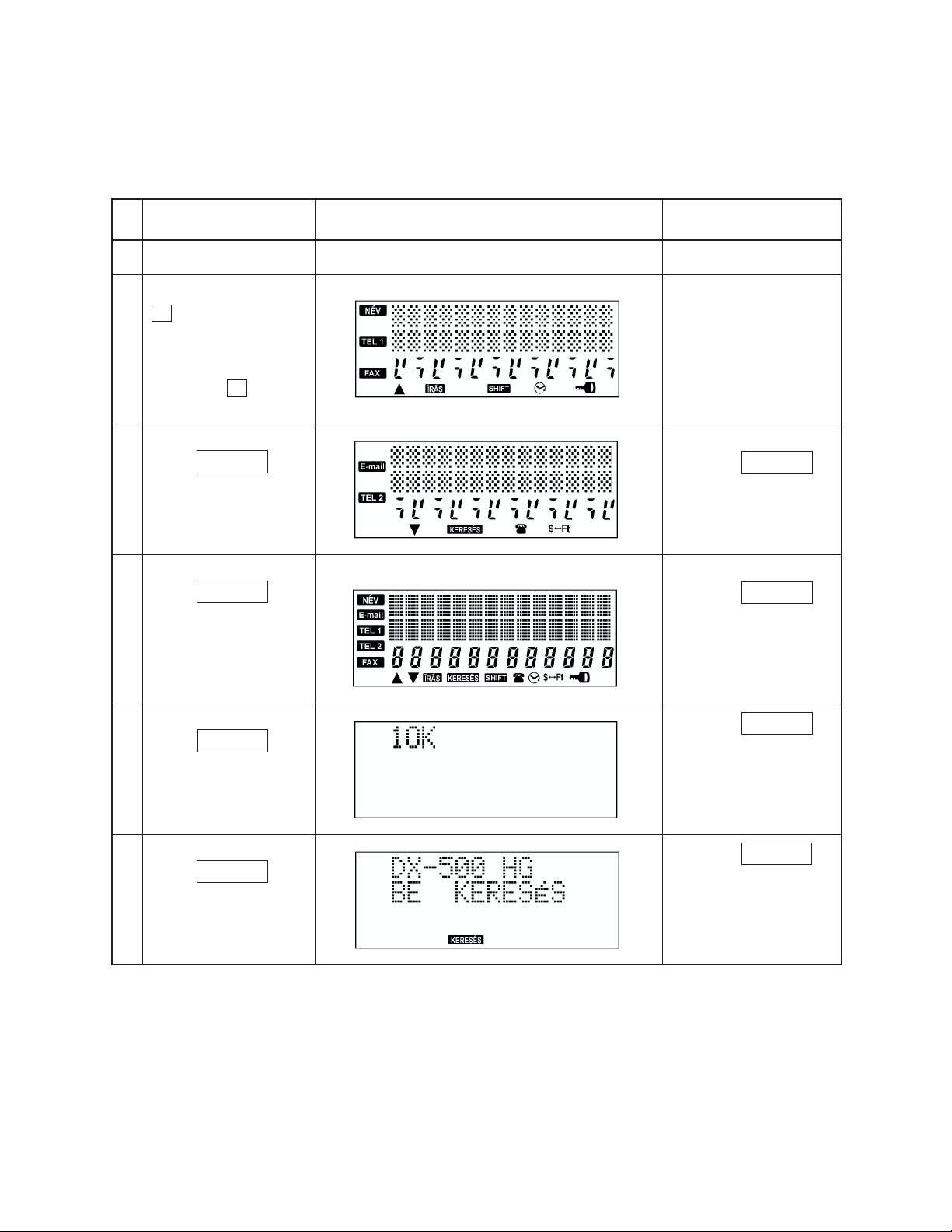
2. OPERATION CHECK
Note: Performing this check, the data saved in the unit will be deleted.
Therefore, save the data to another unit referring to “ 3. DATA TRANSFER”
( page 6 of this Service Manual) before performing this check.
KEY OPERATION
No.
Turn the unit off.
1
While holding down
G button, press
RESET button. Then
2
stop to press RESET
button. Next, stop to
hold down G
button.
No display
LCD DISPLAY
NOTES
At the time of stopping
to press RESET button,
buzzer sound is
emitted.
Press SZÓKÖZ
button after 1 ~ 2
3
seconds.
Press SZÓKÖZ
button after 1 ~ 2
4
seconds.
Press SZÓKÖZ
button after 1 ~ 2
5
seconds.
Press SZÓKÖZ
button after 1 ~ 2
6
seconds.
Pressing SZÓKÖZ
button, buzzer sound
is emitted.
All display
Pressing SZÓKÖZ
button, buzzer sound
is emitted.
Pressing SZÓKÖZ
button, buzzer sound
is emitted.
Pressing SZÓKÖZ
button, buzzer sound
is emitted.
— 4 —
Page 5

KEY OPERATION
No.
LCD DISPLAY
NOTES
Press SZÓKÖZ
button after 1 ~ 2
7
seconds.
Press BEÍRÁS
button after 1 ~ 2
8
seconds.
Press BE
button after 1 ~ 2
9
seconds.
No display
Unit’s power will be turned off.
No buzzer sound
No buzzer sound
No buzzer sound
— END —
— 5 —
Page 6

3. DATA TRANSFER
This unit can transfer the stored data to another unit.
Note: Before connecting wires, be sure to reset the Back up unit.
1. Remove the BATT 2 battery cover.
2. Connect 4 terminals on the PCB with wires as shown in the figure below.
User's unit Back up unit
RESET
BATT 1
BATT 2
RESET
BATT 1
BATT 2
Wiring
GND GND
SCLK_ SCLK_
SIN SIN
SOUT SOUT
SCLK_
SIN
GNDSOUT
— 6 —
Page 7

Note: Perform the operation in numerical order.
User's unit
Operation
1 While pushing down RESET
button, press E then release RESET button.
4 Press BEÍRÁS .
5 After the data transmis-
sion....
It takes a few minutes to
complete the data transfer.
7 Press RESET button.
9 Press BE .
Note: Never press BEÍRÁS
as it deletes all
the data.
Display
T?
(Unit emits a buzz.)
T?
(Unit emits a buzz.)
OK
MINDENT TÖRÖL?
NÉV?
Back up unit
Operation
2 While pushing down RESET
button, press F then release RESET button.
3 Press BEÍRÁS .
6 When the data is transferred
properly......
In case the data transfer
ends incomplete......
8 Press RESET button.
0 Press BE .
Note: Never press BEÍRÁS
as it deletes all
the data.
Display
R?
(Unit emits a buzz.)
R?
(Unit emits a buzz.)
OK
MINDENT TÖRÖL?
MINDENT TÖRÖL?
NÉV?
A Press BE (OFF).
4. TROUBLESHOOTING
Before doing the following solutions, save data if possible.
SYMPTOM SOLUTIONCAUSE
No power
No display at all or wrong display
Weak battery Replace batteries
supply circuit
Defective heat seal Replace the heat seal
Defective LCD Replace the LCD
B Press BE (OFF).
ResolderPoor soldering of the power
— 7 —
Page 8

5. SCHEMATIC DIAGRAMS
Main block
— 8 —
Page 9

Key block
— 9 —
Page 10

6. PARTS LIST
N Item Code No. Parts Name Specification Applicable Q R
PCB UNIT
IC1 2105 6304 IC/MOS RH5VT54AA-T1S Common 1 C
N IC2 2105 6439 IC/MOS RH5RL35AA-T1 Common 1 C
IC3 2012 3192 LSI/S-RAM TC55257DFL-7085V Common 1 C
IC5 2113 0374 IC/MOS D353-C Common 1 C
IC6 2105 0686 IC/MOS TC4S69F-TE85R Common 1 C
D1 2390 0364 DIODE/SCHOTTKY MA713-TX Common 1 C
D2, D3, D4 2390 1267 CHIP DIODE MA159A-(TX) Common 3 C
D5 2390 1442 DIODE MA152K-(TX) Common 1 C
L1 3013 2471 INDUCTOR/CHIP ELT5K114C Common 1 C
XTAL 7110 0979 OSCILLATOR/QUARTZ DT-26ST Common 1 C
1 6409 6310 SPRING/BATTERY EF02DB10100 Common 2 C
2 6409 6300 SPRING/BATTERY EF01DB20102 Common 2 C
N 3 3335 6687 LCD AC1CD444T08 DX-500BR 1 B
N 3 3335 6688 LCD AC1CD445T04 DX-500PL 1 B
N 3 3335 6689 LCD AC1CD446T01 DX-500CZ 1 B
N 3 3335 6690 LCD AC1CD447T07 DX-500HG 1 B
N 3 3335 6692 LCD AC1CD448T03 DX-500TR 1 B
N 4 6421 8970 HEAT SEAL FX200P60103 Common 1 B
N 5 6421 8890 PCB ASSY DB38XX3100S*1 DX-500BR 1 B
N 5 6421 9360 PCB ASSY DB38AX3100M*1 DX-500PL 1 B
N 5 6421 9500 PCB ASSY DB38BX3100P*1 DX-500CZ 1 B
N 5 6421 9630 PCB ASSY DB38CX3100L*1 DX-500HG 1 B
N 5 6421 9760 PCB ASSY DB38DX3100S*1 DX-500TR 1 B
The PCB ASSY contains the above elements and COB LSI.
COMPONENTS
6 6418 1080 ELECTRO LUMINESCENCE A341294-1 Common 1 B
7 6419 8180 COVER/BATTERY FAD0L961051 Common 2 C
8 6419 1820 BUTTON/PUSH FB3DB371004 Common 1 C
N 9 6421 8910 CASE/UPPER FAADB391028 DX-500BR 1 C
N 9 6421 9380 CASE/UPPER FAADB391036 DX-500PL 1 C
N 9 6421 9520 CASE/UPPER FAADB391044 DX-500CZ 1 C
N 9 6421 9650 CASE/UPPER FAADB391052 DX-500HG 1 C
N 9 6421 9780 CASE/UPPER FAADB391061 DX-500TR 1 C
N 10 6421 8920 RUBBER/CONTACT LADB3910021 DX-500BR 1 C
N 10 6421 9390 RUBBER/CONTACT LADB3910030 DX-500PL 1 C
N 10 6421 9530 RUBBER/CONTACT LADB3910048 DX-500CZ 1 C
N 10 6421 9660 RUBBER/CONTACT LADB3910056 DX-500HG 1 C
N 10 6421 9790 RUBBER/CONTACT LADB3910064 DX-500TR 1 C
11 6419 8210 CUSHION FH100040601 Common 1 C
N 12 6421 8940 HARD CASE FC1DB371107 DX-500BR 1 X
N 12 6421 9410 HARD CASE FC1DB371069 DX-500PL 1 X
N 12 6421 9550 HARD CASE FC1DB371077 DX-500CZ 1 X
N 12 6421 9670 HARD CASE FC1DB371085 DX-500HG 1 X
Notes: N – New parts R-A : Essential
Q – Quantity B : Stock recommended
R – Rank C : Others
X : No stock recommended
— 10 —
Page 11

N Item Code No. Parts Name Specification Applicable Q R
N 12 6421 9800 HARD CASE FC1DB371093 DX-500TR 1 X
N 13 6421 8950 LABEL HGH00046000 DX-500BR 1 X
N 13 6421 9420 LABEL HGH00045402 DX-500PL 1 X
N 13 6421 9560 LABEL HGH00045500 DX-500CZ 1 X
N 13 6421 9680 LABEL HGH00045607 DX-500HG 1 X
N 13 6421 9810 LABEL HGH00045704 DX-500TR 1 X
14 3122 2380 BUZZER EFB-S55C41A8 Common 1 X
15 6408 5830 RUBBER/KEY LADB0140101 Common 1 C
N 16 6421 8960 CASE/LOWER FABDB371091 DX-500BR 1 X
N 16 6421 9430 CASE/LOWER FABDB371074 DX-500PL 1 X
N 16 6421 9570 CASE/LOWER FABDB371082 DX-500CZ 1 X
N 16 6421 9690 CASE/LOWER FABDB371201 DX-500HG 1 X
N 16 6421 9820 CASE/LOWER FABDB371104 DX-500TR 1 X
17 6510 4500 ADHESIVE TAPE HGFC0000501 Common 1 X
18 6410 2180 SCREW MAA80012302 Common 2 C
N 19 5610 9270 PLATE/POLARIZATION NUH-26 Common 1 C
20 6512 1080 NUT MD100000602 Common 2 X
N 21 6419 8200 ADHESIVE TAPE EEDB3710036 Common 1 C
Parts prices will be informed separately by Parts Price List.
Notes: N – New parts R-A : Essential
Q – Quantity B : Stock recommended
R – Rank C : Others
X : No stock recommended
— 11 —
Page 12

7. EXPLODED VIEW
— 12 —
Page 13

CASIO TECHNO CO.,LTD.
Overseas Service Division
8-11-10, Nishi-Shinjuku
Shinjuku-ku, Tokyo 160-0023, Japan
 Loading...