

Page 1
(without price)
INDEX
DL-220LA(GY) (LX-226IY)
DL-250LA(GYB) (LX-226JY)
DR-120LA(WE) (LX-226AY)
SEP. 1995
DR-120LADL-220LA
R
Page 2

CONTENTS
1. SPECIFICATIONS ......................................................................................................... 1
2. BLOCK DIAGRAM ........................................................................................................ 2
3. CPU (MN158418YCY) PIN FUNCTION......................................................................... 3
4. TROUBLESHOOTING................................................................................................... 4
5. DIAGNOSTIC................................................................................................................. 5
6. SCHEMATIC DIAGRAM................................................................................................ 6
7. DISASSEMBLY VIEW ................................................................................................... 8
8. PARTS LIST .................................................................................................................. 9
Page 3

1. SPECIFICATIONS
Functions: 4 basic arithmetic operations (+, -, ×, ÷), constants for ×/÷, sub-total/total/
grand total, item counting, ADD mode calculations, repeat calculations,
memory calculations, percentage calculations and various kinds of practical
calculations.
Decimal point: Full floating, and fixed (0, 1, 2, 3, 4 or 6) with round-off, round-up or cut-off.
Capacity: 12digits
Display: Digitron tube panel
Ambient temperature range: 0°C — 40°C (32°F — 104°F)
Power supply: AC 100/120/220 or 240 V (±10V), 50/60 Hz ••••• Fixed
*Rated current and voltage are printed on the calculator.
Dimensions: 83mmH × 214mmW × 376mmD
(3 1/4"H × 8 3/8"W × 14 3/4"D) including rollholder.
Weight: 1.7kg (3.8 lbs)
— 1 —
Page 4
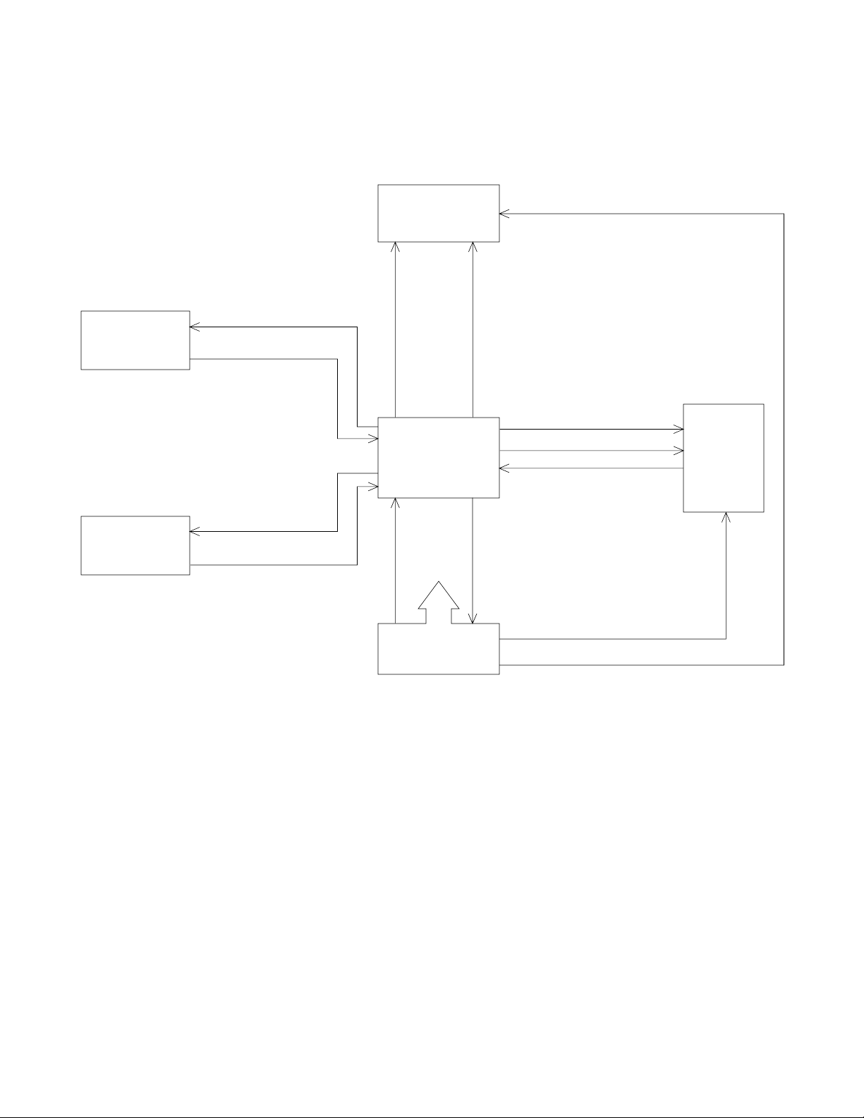
2. BLOCK DIAGRAM
Slide switch
Keyboard
Segment signal
S1~S7,SAP,SDP
SO1~SO7
SI1~SI3,SI5
KO1~KO8
KI1~KI6
Display tube
13-MT-31GB
CPU
MN158418YCY
VDD
GND
VSS
Digital signal
D1~D13
Ribbon shift signal
Character selective signal
Timing pulse
Motor control signal
VF1,VF2
Printer
M-80
Power supply
circuit
Motor power supply
Detector power supply
— 2 —
Page 5

3. CPU (MN158418YCY) PIN FUNCTION
Pin No.
1~7, 64
8~12
13
14
15
16
17
18~30
31, 32
33~39
Signal
P00~P13
P20~P22, P32, P33
IRQ
DEBIN
IRQCNT
P40
P41
P42, P43, P50~P53
P70~P73, P80~P82
P83, P90
P91~P93
PA0~PA3
I/O
Out
In
In
In
In
Out
Out
Out
Out
Out
Function
Common signal for keyboard
Key signal from keyboard
Timing pulse signal from printer
Not used
VDD (33V, 30mA)
Motor control signal
Ribbon shift signal for printer
Character selective signal for printer
Character selective signal for printer,
Segment signal for display
Segment signal for display,
Common signal for slide switch
40
41~43
44~56
57
58
59, 60
61
63
P60
P61~P63
PB0~PB3
PC1~PC3
PD0~PD3
PE0
VPP
VDD
OCS1, OCS2
VSS
RST
Out
In
Out
—
—
I/O
—
In
VDD (33V, 30mA)
Signal from slide switch
Digit signal for display
GND terminal
VDD terminal
Clock signal for CPU
VSS terminal
Signal from slide switch, Reset signal
— 3 —
Page 6

4. TROUBLESHOOTING
Trouble
1) Does not work
at all.
2) No display.
3) No print.
4) Poor display.
Cause
• Defective power transformer
• Defective LSI
• No voltage at VF1, VF2
• No digit signal or no segment
signal
• Defective display tube
• Poor voltage VM
• Defective motor
• Defective LSI
• Short or open circuits
between digit signals and
segment signals.
Checkpoint
Secondary voltage of
transformer
Waveforms of each pin
VF1, VF2
Signal D1 ~
S1 ~
Between LSI and
display tube
Note
VDD, VSS, VM, VF1, and
VF2 are OK?
Check the pulse signals
from LSI.
If VF1, VF2, Digit and
Segment signals are OK.
VM=11V (while printing)
5) Poor printing
• Motor does
not stop.
• Missing of
digits
• Defective display tube
• Timing signal is bad.
• Defective printer magnet
Refer to the printer service manual published separately.
Check detector of printer
block and timing signal.
— 4 —
Page 7

5. DIAGNOSTIC
STEP
1
2
3
4
5
6
7
8
9
10
11
12
13
14
15
16
MODE SWITCHES
ON F 6
ON F 6
ON F 6
ON F 6
ON F 6
PRINT F 6
PRINT F 6
PRINT CUT 6
PRINT CUT 4
PRINT UP 3
PRINT UP 2
PRINT 5/4 1
PRINT 5/4 0
PRINT 5/4 ADDX
PRINT 5/4 ADDX
PRINT 5/4 ADDX
OPERATION
1 00 TM
C
8 – ÷ 9 % ◊/#
▲
CA
1 2 3 4 ÷
7 6 5 +
M+
M+
M–
÷ 5 MU/MD
+
+
M◊
M❊
CA 1 ÷ ÷ 1 =
DISPLAY
100.
0.
-888.888888888
-888.88888888
0.
1234.
1.61307189542
M 1.613071
M 1.6131
M 1.614
M 1.54
M 3.1
M 5.
1.613
1.613
K 0.01
PRINT
[-]
[88.8888888888]
1.234 • ÷
765 • =
1.61307189542+
1.613071 M+
1.6131 M+
[1.614 M+]
1.614 ÷
5 • %M
0.08 -%
1.54
1.5 +
2 • +
1.613 M◊
1.613 M*
• • 0 • •
NOTE
The character with
"[ ]" will be printed
by red ink.
PRINT 5/4 ADD+
17
18
PRINT 5/4 ADD+
ITEM+ 5/4 ADD+
19
20
ITEM+/– 5/4 ADD+
ITEM+/– 5/4 ADD+
21
23
ITEM+/– 5/4 ADD+
ITEM+/– 5/4 ADD+
24
X 1 – 1 –
◊/#
◊/#
– ❊
G
FEED
AC
-0.02
[- 1 • =]
-0.02
[- 0 • 02◊]
002
-0.02
[- 0 • 02◊]
-0.03
001
[- 0 • 03 ❊]
001
-0.03
[- 0 • 03G❊]
Paper feeding
0.
1 • ÷
1• K÷
0 • 01 ÷
1 • =
0 • 01
0 • 01 X
[- 0 • 01+]
[0 • 01-]
[0 • 01 -]
[0 • 01 -]
• • 0 • •
Press the button 2
or 3 seconds
continuously.
— 5 —
Page 8

6. SCHEMATIC DIAGRAM
6-1. Main Board
— 6 —
Page 9

— 7 —
6-2. Key Matrix
Page 10

7. DISASSEMBLY VIEW
8
7
21
19
6
5
— 8 —
20
12
15
17
10
16
13
23
14
9
11
18
24
25
4
18
3
2
1
26
22
27
24
27
× 2
25
23
INPUT
26
OUTPUT
Voltage
100V
120V
220V
240V
Connection
Power Cord
Black
Projection side
Projection side
Marking side
Brown
Blue
Brown
Blue
Transformer
Black
Yellow
Blue
Black
Black
White
Black
Red
Page 11

8. PARTS LIST
— 9 —
Page 12

— 10 —
Page 13

8-11-10, Nishi-Shinjuku
Shinjuku-ku, Tokyo 160, Japan
Telephone: 03-3347-4926
 Loading...