

Page 1
DC-7800RS (ZX-725)
DC-8500RS (ZX-726)
JAN. 1997
(without price)
R
Page 2

CONTENTS
SPECIFICATIONS .............................................................................................................. 1
OPERATION CHECK ......................................................................................................... 2
DATA TRANSFER.............................................................................................................. 3
TROUBLESHOOTING........................................................................................................ 4
SCHEMATIC DIAGRAMS .................................................................................................. 5
PARTS LIST ....................................................................................................................... 7
EXPLODED VIEW .............................................................................................................. 8
Page 3

SPECIFICATIONS
Display: Liquid crystal display
Power supply: Two lithium batteries (CR2032)
Power consumption: 0.1 W
Current consumption: DC-7800RS When AC key is pressed; Max. 18.7 µA. Typ. 9.5 µA
While Power OFF; Max. 14.7 µA
While buzzing; Max. 765 µA
When backlighting; Max. 16,500 µA
DC-8500RS When AC key is pressed; Max. 20.7 µA. Typ. 10.5 µA
While Power OFF; Max. 16.7 µA
While buzzing; Max. 767 µA
When backlighting; Max. 16,500 µA
Battery life: Approx. 1 year (one hour operation per day with two backlight opera-
tions and one daily alarm operation)
Auto power off: Approx. 6 minutes after last key operation
Ambient temperature range: 0 °C ~ 40 °C (32 °F ~ 104 °F)
Dimensions: 15.3 (H) × 134 (W) × 92 (D) mm .........Folded
(5/8" (H) × 5 1/4" (W) × 3 5/8" (D))
10.9 (H) × 134 (W) × 180 (D) mm .......Unfolded
(3/8" (H) × 5 1/4" (W) × 7 1/8" (D))
Weight: DC-7800RS; 121.5 g (4.3 oz)/DC-8500RS; 122 g (4.3 oz) including
batteries
— 1 —
Page 4
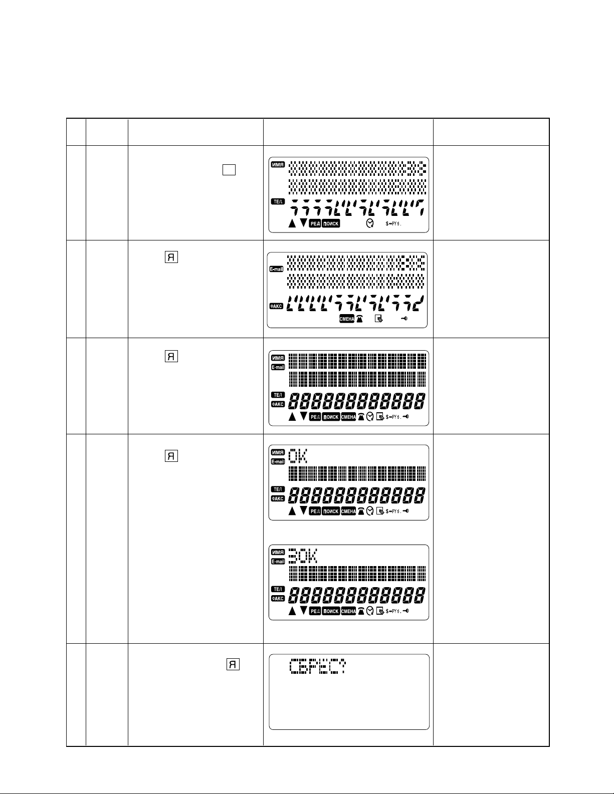
OPERATION CHECK
Note: Before performing the operation, save the data to another unit referring “DATA TRANSFER”
on page 3.
No.
MODE
KEY
DISPLAY NOTE
While pushing down the RESET button, press G then
release the RESET button.
1
Press for about 1 second.
2
Press for about 1 second.
3
The unit emits a buzz.
RESET button is located
on the back of the unit.
Press for about 1 second.
DC-8500RS
4
DC-7800RS
DC-8500RS: Press for
about 1 sec-
5
DC-7800RS: Press RESET
ond.
button.
If the unit is faulty, LCD
indicates “NG” instead
of “OK”.
— 2 —
Page 5

DATA TRANSFER
The DC-7800RS/8500RS can transfer the stored data to another DC-7800RS/8500RS.
Note: Before connecting wires, be sure to reset the Back up unit.
1. Remove the BATT 2 battery cover.
2. Connect 4 terminals on the PCB with wires as shown in the figure below.
User's unit Back up unit
RESET
BATT 1
BATT 2
RESET
BATT 1
BATT 2
Wiring
GND GND
SCLK_ SCLK_
SIN SIN
SOUT SOUT
SCLK_
SIN
GNDSOUT
— 3 —
Page 6

Note: Perform the operation in numerical order.
User's unit
Operation
1 While pushing down RESET
button, press E then release RESET button.
4 Press .
5 After the data transmis-
sion....
It takes a few minutes to
complete the data transfer.
7 Press RESET button.
9 Press .
Note: Never press as it
deletes all the data.
Display
T?
(Unit emits a buzz.)
T?
(Unit emits a buzz.)
END
USED FREE
5250 60220
The above example
is DC-8500RS display. The numbers
vary depending on
the quantity of data.
Back up unit
Operation
2 While pushing down RESET
button, press F then release RESET button.
3 Press .
6 When the data is transferred
properly......
In case the data transfer
ends incomplete......
8 Press RESET button.
0 Press .
Note: Never press as it
deletes all the data.
Display
R?
(Unit emits a buzz.)
R?
(Unit emits a buzz.)
END
NG!
or
USED FREE
5250 60220
The above example
is DC-8500RS display. The numbers
vary depending on
the quantity of data.
A Press (OFF).
TROUBLESHOOTING
Before doing the following solutions, save data if possible.
SYMPTOM SOLUTIONCAUSE
No power
No display at all or wrong display
Weak battery Replace batteries
supply circuit
Defective heat seal Replace the heat seal
Defective LCD Replace the LCD
B Press (OFF).
ResolderPoor soldering of the power
— 4 —
Page 7

SCHEMATIC DIAGRAMS
Main block
— 5 —
Page 8

Key block
— 6 —
Page 9

PARTS LIST
N Item Code No. Parts Name Specification Version Q R
PCB ASS'Y
N IC1 2105 6304
IC2 2105 5894
IC3 2011 3955
IC4 2011 3955
IC5 2114 5747
D1 6510 4940
D2~5 2390 1442
L1 3013 2471
X1 6510 4550
N 1 3335 6537
2 6419 2230
DETECTOR RH5VT54AA-T1
REGULATOR RH5RL33AA-T1
LSI uPD43256BGU-B12
LSI uPD43256BGU-B12
IC ABD353X0000
DIODE BC10MA71307
CHIP DIODE MA152K-(TX)
CHIP INDUCTORS ELT5K114C
CRYSTAL BD0063P2509 (DT-26S)
LCD
HOT MELT FILM FX200P50604
AC10CD44105 Common 1
Common 1
Common 1
Common 1
DC-8500RS 1
Common 1
Common 1
Common 4
Common 1
Common 1
Common 1
B
B
B
B
B
B
B
B
B
A
A
N 3 6419 8060 PCB ASS’Y DB39XX0300R*1 DC-7800RS 1
N 3 6419 8070 PCB ASS’Y DB39AX0300L*1 DC-8500RS 1
The PCB ASS'Y contains the above elements and COB LSI.
COMPONENT
4 6418 1080
N 5 6419 8180
6 6419 1820
N 7 6419 8150
N 7 6419 8160
N 8 6419 8170
N 9 6419 8210
N 10 6419 8220
N 10 6419 8230
N 11 6419 8240
N 11 6419 8250
N 12 3122 3513
13 6408 5830
N 14 6419 8260
15 6510 4500
EL PANEL Z723 A341294-1
BATT COVER
PUSH BUTTON FB3DB371004
UPPER CABINET
UPPER CABINET
RUBBER SHEET
SPONGE
HARD CASE
HARD CASE
OPERATION LABEL
OPERATION LABEL
BUZZER
RB SHEET LADB0140101
LOWER CABINET
BUZZER TAPE HGFC0000501
FADOL961051 Common 2
FAADB391001 DC-7800RS 1
FAADB391010 DC-8500RS 1
LADB3910005 Common 1
FH100040601 Common 1
FC1DB371042 DC-7800RS 1
FC1DB371051 DC-8500RS 1
HGL00006103 DC-7800RS 1
HGL00006201 DC-8500RS 1
CK225P30024 Common 1
FABDB371058 Common 1
Common 1
Common 1
Common 1
Common 1
B
B
B
C
X
X
X
X
C
X
X
X
X
X
X
X
X
Parts prices will be informed separately by Parts Price List.
Notes: N – New parts R – A : Essential
Q – Quantity used per unit B : Stock recommended
R – Rank C : Others
X : No stock recommended
— 7 —
Page 10

EXPLODED VIEW
2
1
10
11
7
8
4
9
3
12
15
14
6
13
— 8 —
5
Page 11

MA0300171A
 Loading...