

Page 1
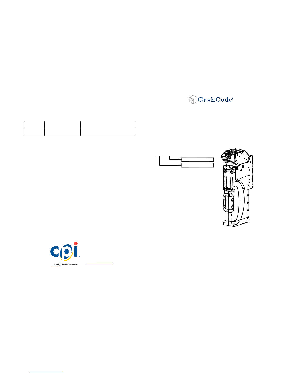
The Part Number on the Label includes Hardware
Part Number and Software Part Number.
Example
BNL-3015 AAXX-XXXX
Software Part Number
Hardware Part Number
5. General Specifications:
CURRENCY AND INTERFACES See Software Description document
ELECTRICAL SPECIFICATION:
Operating
Voltage
Maximum Operating
Current
Maximum Current
12 V DC
Idle: 300 mA
Bill processing: 1.3 A
4.0 A
Use only current limiting CSA or UL recognized Power Supply.
OPERATING TEMPERATURE: -0 to +50 degrees Celsius
TOTAL WEIGHT:
8.6 Kg (19 lb)
FEATURES: Single Width Loading Validator Head, Tract width 67 mm
Optics Type A
Cassette 3000 notes
ENCLOSURE: BNL Bill Validator
User's Guide
Software description
CPI | Crane Payment Innovations
CashCode Brand
2720 Steeles Ave. West, Units 2-3
Concord, ON, Canada, L4K 4S3
Phone: +1 905 303-8874
Toll Free: +1 800 584-2633
Fax: +1 905 303-8875
Website: www.cranepi.com
http://support.cashcode.com
2014 Crane Payment Innovations PT# UG-
BNL-3015_B 06/14
BNL Bill Validator
User’s Guide
Bulk Note Loader
Hardware part #
BNL-3015
Page 2
123456
789101112
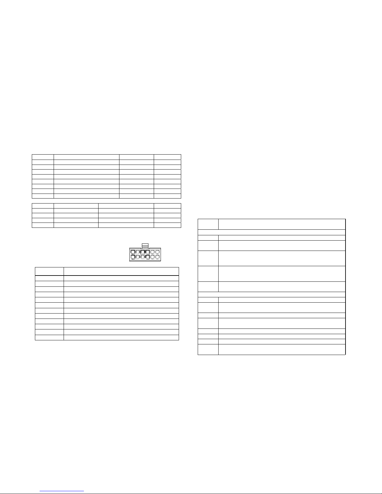
1. Typical DIP Switches Setting
To access switches open the back lid. Swi t che s ar e lo ca t e d on the ri g ht si d e of
the lid, as observed from the bezel. The “up” state is defined as the switch
position closer to the top cover of the lid.
SW. #1 “Down” State
“Up” State
Default
SW 1.1 1-st Bill Enable controlled by host 1-st bill Disable down
SW 1.2 2-nd Bill Enable controlled by host
2-nd Bill Disable
down
SW 1.3 3-rd Bill Enable controlled by host
3-rd Bill Disable
down
SW 1.4 4-th Bill Enable controlled by host
4-th Bill Disable
down
SW 1.5 5-th Bill Enable controlled by host
5-th Bill Disable
down
SW 1.6 6-th Bill Enable controlled by host
6-th Bill Disable
down
SW 1.7 7-th Bill Enable controlled by host
7-th Bill Disable
down
SW 1.8 8-th Bill Enable controlled by host
8-th Bill Disable
down
SW#2 “Down” State “Up” State Default
SW 2.1 Four Way
One Way
down
SW 2.2 High security disabled
High security enabled
down
SW 2.3 19200 bps data rate
9600 bps data rate
down
SW 2.4 Not used
Not used
down
2. Interface Connector Pinout
Mating Connector:
Socket 43025-1200 (Molex);
Contact 43030-0002 (Molex).
Terminal Circuit
1 Signal Ground
2 RS232_DATA_TO_PC
3 GND
4 GND
5 +12V
6 +12V
7 RS232_DATA_FROM_PC
8 BUS RESET
9 GND
10 GND
11 +12V
12 +12V
3. Power connections
+12 V lines must be connected together directly at the connector.
Power ground lines must be connected together directly at the connector,
thus forming a power ground star point; 12V power source must use this star
point.
Signal ground may not be connected to power ground star point; it should be
connected to the host signal ground instead.
Bus reset line, host Rx and Tx lines are all RS232 signal level lines.
4. Diagnostics
Count the number of flashes and compare with the diagnostic chart below:
## of
flashes
Malfunction
Boot-related flashes (green flashes on red background)
1 Memory write error – check memory stick for proper contact
2
Firmware set incomplete – please obtain the missing part and
install
3
A required card is missing – please install the card required;
normally reported when the main firmware component is
missing/corrupt
4
Update policy violation – please install the card required to
regain policy rights; most common reason – a ONE UPDATE
or NDEG card is missing
5
Generic error – a fatal boot error, please contact technical
support
Operation flashes (red flashes on dark background)
1 Box removed – please verify the drop box is secured in place
2
Boot invocation error – please verify that a required card is in
place
3 Box full – check the drop box and make sure it’s not full
4
Stacker plate stuck – verify that drop box is fully inserted and
stacker plate has room to move inside the drop box
6 Optical sensor failure – contact technical support
7 Magnetic sensor failure – contact technical support
11 Bill jam – please verify the bill pathway is clear
14
Firmware integrity problem – please verify that all firmware
components are installed
 Loading...