

Page 1

INSTALLATION, OPERATION & MAINTENANCE MANUAL
IOM-1000HP-
MODEL 1000HP - BASIC
PRESSURE REDUCING REGULATOR
SECTION I
I. DESCRIPTION AND SCOPE
The Model 1000HP is a pressure reducing regulator used to control downstream (outlet or P2) pressure to levels
between 10 and 300 psig (0.7-20.6 Barg). Sizes are 1/2", 3/4", 1", 1-1/4", 1-1/2" and 2" (DN15, 20, 25, 32, 40 and
50).
The unit is designed for liquid, gaseous or steam service with proper trim utilization, and proper jet selection.
Refer to Technical Bulletin 1000HP-TB for sizing, application and selection recommendations.
Installation, operation and maintenance manuals (IOM's) also exist for the following other Model 1000 products:
1000LP-Basic 1000HP-Differential 1000HP-Cryogenic
SECTION II
Basic
12-13
CAUTION
For welded installations, all internal trim parts,
seals and diaphragm(s) must be removed from
regulator body prior to welding into pipeline. The
heat of fusion welding will damage non-metallic
parts if not removed. NOTE: This does not apply
to units equipped with extended pipe nipples.
II. INSTALLATION
1. An inlet block valve should always be installed.
An outlet block valve is recommended.
2. If service application is continuous such that
shut down is not readily accomplished, it is rec om mended that an inlet block valve and a man u al
bypass valve be installed.
3. Pipe unions must be installed to allow removal
from piping. Trim can only be changed by unit
removal from pipeline. If fl anges are utilized, a
lap joint fl ange is required on the inlet end of the
regulator to help align bolt holes as the cylinder
screws into place.
4. An outlet pressure gauge should be located ap prox i mate ly ten pipe diameters down stream, and
with in sight.
5. All installations should include a downstream relief de vice if the inlet pressure could exceed the
pressure rating of any downstream equip ment or
the maximum outlet pressure rating of the unit.
CAUTION
Installation of adequate overpressure protection
is recommended to protect the regulator from
overpressure and all downstream equipment from
damage in the event of regulator failure.
Recommended Piping Schematic
For Pressure Reducing Station
CAUTION
The maximum outlet pressure listed on the name plate is the “upper operative limit” for the sens ing
di a phragm. High er pres sures could damage the di a phragm. (Field hy dro static tests fre quent ly de stroy
dia phragms. DO NOT HY DRO STAT IC TEST THRU
AN IN STALLED UNIT; ISO LATE FROM TEST.)
6. Clean the pip ing of all foreign material in clud ing
chips, welding scale, oil, grease and dirt before
installing the regulator. Strainers are rec om mended.
Page 2

7. In placing thread sealant on pipe ends prior to
en gage ment, ensure that excess material is re moved and not allowed to enter the regulator upon
startup.
vertical pipe line. Rec om mend ed po si tion is with
spring cham ber ver ti cal upwards. Orient to pre vent the spring cham ber vent hole from col lect ing
rain wa ter or debris.
8. Flow Direction: Install so the fl ow direction
match es the arrow cast on the body.
9. For best performance, install in well drained hor i zon tal pipe, properly trapped if a steam ser vice
application.
10. Basic regulator may be rotated around the pipe
axis 360°
, and may be installed in a horizontal or
III. PRINCIPLE OF OPERATION
1. The Model 1000 is available in two variations:
1000LP (larger diaphragm) for downstream pressure control from 1-30 psig (0.07-2.06 Barg);
1000HP (small er diaphragm) for down stream
pressure control from 10-300 psig (0.7-20.6
Barg), body size dependent.
2. Movement occurs as pressure variations reg ister
on the diaphragm. The registering pres sure is
the outlet, P
range spring opposes di a phragm move ment. As
out let pressure drops, the range spring push es
the diaph ragm down, opening the port; as outlet
pressure increases, the dia phragm pushes up
and the port closes.
3. The Model 1000 includes a rocker arm in its op er a tion al mechanism. The rocker arm allows the
regulator to operate fl ow-to-open (FTO), rather
than conventional fl ow-to-close (FTC), which
increases rangeability.
, or downstream pressure. The
2
11. Regulators are not to be direct buried under-
12. For insulated piping systems, recommen dation is
13. Cashco does not recommend fi eld welding on the
SECTION III
5. The FTO design also is limited by a minimum
6. The Model 1000 includes an aspiration jet ef-
ground.
to not insulate regulator.
cyl in der (inlet) end of the body due to the pos si bil i ty of warpage.
setting is capable for a given inlet P
pressure.
1
This is a function of the ratio of the port area to
diaphragm area. It is possible for there to be too
high of an inlet pressure for the regulator to close
off against. (Refer to 1000-TB, Tables 9 through
12 for limits.) Reduced ports, Option 1000-12,
allow lower down stream (P
or outlet) pressure
2
settings for a given up stream (P1 or inlet) pres sure
level.
pres sure drop. If the pressure drop is below 5
psid, an Option 1000-17 piston spring should be
utilized to assist open ing the piston.
fect, due to the clearance of the piston from the
body near the outlet. These clear ances vary as
to whether the fl uid is a gas (including steam), a
liquid, or a viscous liquid (requires Option 1000-
27). Jets must be se lec ted to match one of these
three general fl uids. An improper jet selection will
reduce perfor mance.
4. Due to the FTO design, there is a limit as to how
low of a downstream (P
or outlet) pressure level
2
7. A complete diaphragm failure will cause the regulator to fail open.
SECTION IV
IV. STARTUP
1. Start with the block valves closed. A bypass
valve may be used to maintain outlet pressure
in the downstream system without changing the
fol low ing steps.
2. Relax the range spring by turning the adjusting
screw counterclockwise (CCW) a min i mum of
three (3) full revolutions. This re duces the outlet
(down stream) pres sure set point.
2 IOM-1000HP-Basic
3. If it is a “hot” piping system, and equipped with
a bypass valve, slowly open the bypass valve
to pre-heat the system piping and to allow slow
expansion of the piping. Ensure proper steam
trap operation if installed. Closely monitor out let
(downstream) pressure via gauge to ensure not
over-pressurizing. NOTE: If no bypass valve is
installed, extra caution should be used in start ing
up a cold system; i.e. do everything slowly.
Page 3

4. Crack open the outlet (downstream) block
valve.
5. Slowly open the inlet (upstream) block valve ob serv ing the outlet (downstream) pressure gauge.
Determine if the regulator is fl owing. If not, slowly
rotate the regulator adjusting screw clockwise
(CW) until fl ow begins.
8. When fl ow is established steady enough that the
outlet (downstream) block valve is fully open, begin to slowly close the bypass valve if in stalled.
9. Develop system fl ow to a level near its expected
normal rate, and reset the regulator set point by
turning the adjusting screw CW to increase outlet
pressure, or CCW to reduce outlet pres sure.
6. Continue to slowly open the inlet (upstream) block
valve until fully open.
7. Continue to slowly open the outlet (down stream)
block valve, especially when the down stream piping system isn't pres surized. If the outlet (downstream) pressure exceeds the de sired pres sure,
close the block valve and go to Step 2, then return
to Step 4.
SECTION V
V. SHUTDOWN
1. On systems with a bypass valve, and where sys tem pressure is to be maintained as the regulator
is shut down, slowly open the bypass valve while
closing the inlet (up stream) block valve. Fully
close the inlet (up stream) block valve. (When on
bypass, the system pressure must be constantly
observed and manually reg u lat ed.) Close the
outlet (downstream) block valve.
SECTION VI
VI. MAINTENANCE
WARNING
SYSTEM UNDER PRESSURE. Prior to per form ing
any maintenance, isolate the regulator from the
system and relieve all pressure. Failure to do so
could result in personal injury.
A. General:
1. Maintenance pro ce dures hereinafter are
based upon removal of the unit from the
pipeline where in stalled.
10. Reduce system fl ow to a minimum level and
ob serve set point. Outlet pressure will rise from
the set point of Step 9. The maximum rise in
outlet pressure on de creas ing fl ow should not
exceed the stated upper limit of the range spring
by greater than 30%; i.e. 10–40 psig (0.7-2.75
Barg) range spring, at low fl ow the outlet pres sure
should not exceed 52 psig (3.6 Barg). If it does,
consult factory.
CAUTION
Do not walk away and leave a by passed regulator
un at tend ed.
2. If the regulator and system are to both be shut down, slowly close the inlet (upstream) block
valve. Close the outlet (downstream) valve only
if reg u la tor removal is required.
4. Regulators originally supplied as “oxygen
cleaned” (Options 1000-55) are assembled
using special gasket sealant, Fluorolube
GR-362 1, or equivalent. Cashco, Inc. rec om mends following factory cleaning specifi cation #S-1134, or equiv a lent. Con tact
factory for details.
B. Diaphragm Replacement:
1. Securely install the body (1) in a vise with the
spring chamber (2) directed up wards.
WARNING
2. Owner should refer to owner's proce dures for
removal, handling and cleaning of re us able
parts, and disposal of nonreusable parts, i.e.
gaskets, suitable sol vents, etc.
3. If desired, the gaskets may be lubricated with
a light oil pro vid ed it is com pat i ble with the
fl uid.
3 IOM-1000HP-Basic
SYSTEM UNDER COMPRESSION. Prior to re mov ing
fl ange bolts, relieve spring com pres sion by backing
out the adjusting screw. Failure to do so may result
in fl ying parts that could cause personal injury.
2. Remove closing cap (31) if provided. Relax
range spring (27) by turning adjusting screw
(6) CCW until removed from spring chamber
(2).
1
Product of Fisher Scientifi c Company
Page 4

3. Paint or embed a match mark between body
casting (1) and spring chamber casting (2)
along fl anged area.
4. Remove all diaphragm nuts (9) and bolts (8).
Remove nameplate (28).
5. Remove spring chamber (2), range spring
(27) and spring button (4).
NOTE: The text hereafter will refer to “pusher
plate and stud" (13)" as a single part, for
1/2" – 1-1/4" sizes (DN15-DN32), and as two
sep a rate parts, the “pusher plate (5)” and a
“push er plate stud" (13)” for sizes 1-1/2"
and 2" (DN40 & DN50).
6. Pry up the diaphragm(s) (20) and diaphragm gasket (19) around the perimeter of
the body (1) diaphragm fl ange to ensure
that the diaphragm(s) (20) are not “sticking”.
(Dia phragm gasket (19) is not used with a
com po si tion (soft) diaphragm.)
7. Remove the diaphragm sub-assembly by
slid ing the pusher plate and stud (13) and
nut (11) in the direction of the regulator's
inlet, ap prox i mate ly 1/2"-3/4" (12-20 mm).
The push er plate and stud (13), stud nut (10),
and stud collar (16) should disengage with
the rocker arm (14) slot. Lift vertically for the
diaphragm sub-assembly re mov al.
8. Place the pusher plate stud (13) in a sepa rate
vise, gripping the stud (13) on the hex ago nal
cast-in-place edges located on the un der neath side of the pusher plate stud. NOTE:
Do not remove the stud nut (10), stud collar
(16) and the location locking cotter pin (15).
Loosen and remove nut (11).
9. Remove pressure plate (3) by lifting.
10. Pry loose pusher plate and stud (13) from
diaphragm(s) (20) or from pusher plate gas ket (12). (Pusher plate gasket (12) is not
used with a composition (soft) diaph ragm.)
Remove the diaphragm(s) (20).
Diaphragm sub-assembly consists of items (10), (11), (12),
(13), (15), (16) and (20). (Metal diaphragm de sign).
14. Install new diaphragm(s) (20) over pusher
plate and stud (13). NOTE: Refer to the quan-
tity of diaphragms (20) incorporated per the
bill of materials listing. Depending on outlet
pressure level, various quantities of metal
diaphragms will be “stacked”.
15. Inspect pressure plate (3) to ensure no
de for ma tion due to over-pressurization. If
de formed, bent, or otherwise distorted, re place.
16. Ensuring that the curved outer rim of the pres sure plate (3) rests against the dia phragm (20)
directly, place the pressure plate (3) over the
pusher plate and stud (13). Place nut (11)
onto the stud (13) and tighten. Rec om
mend ed
torques are as follows:
Body
Size
1/2"
3/4" – 1-1/4"
1-1/2" & 2"
DN15
DN20-DN32
DN40-DN50
Brass Trim
Metal/Comp
Diaphragm
25-30 ft-lbs
35-45 ft-lbs
50-60 ft-lbs
34-41 N-m
47-61 N-m
68-81 N-m
Stainless Trim
Metal
Diaphragm
45-50 ft-lbs.
45-50 ft-lbs.
80-90 ft-lbs.
61-68 N-m
61-68 N-m
108-122 N-m
Comp.
Diaphragm
25-30 ft-lbs.
35-45 ft-lbs.
50-60 ft-lbs.
34-41 N-m
47-61 N-m
68-81 N-m
11. Remove pusher plate gasket (12) from
push er plate and stud (13).
12. Clean gasket sealing surface of pusher plate
and stud (13) thoroughly.
13. Install new pusher plate gasket (12), if re quired, over pusher plate and stud (13).
(DO NOT USE FIN GERS TO HOLD DI A PHRAGMS
(20) DURING TIGHT EN ING OF NUT (11).) Use two
fl ange bolts (8) to keep multiple di a phragms (20) bolt
holes prop er ly aligned while tight en ing the stud nut
(10).
CAUTION
4 IOM-1000HP-Basic
Page 5
17. Remove cotter pin (15) securing stud nut (10)
to lower end of pusher plate and stud (13), and
replace with a new pin (15). (Do not allow
the stud nut (10) to move when the cotter
pin (15) is removed.)
as those originally supplied. Sub sti tu tion may
cause improper gasket com pres sion. It may
also adversely change the di a phragm setting,
which will affect the unit's per for mance, i.e.
Option 1000-45, non-as bes tos construction
utilizes special gaskets.
18. Remove rocker arm shaft (17) and rocker
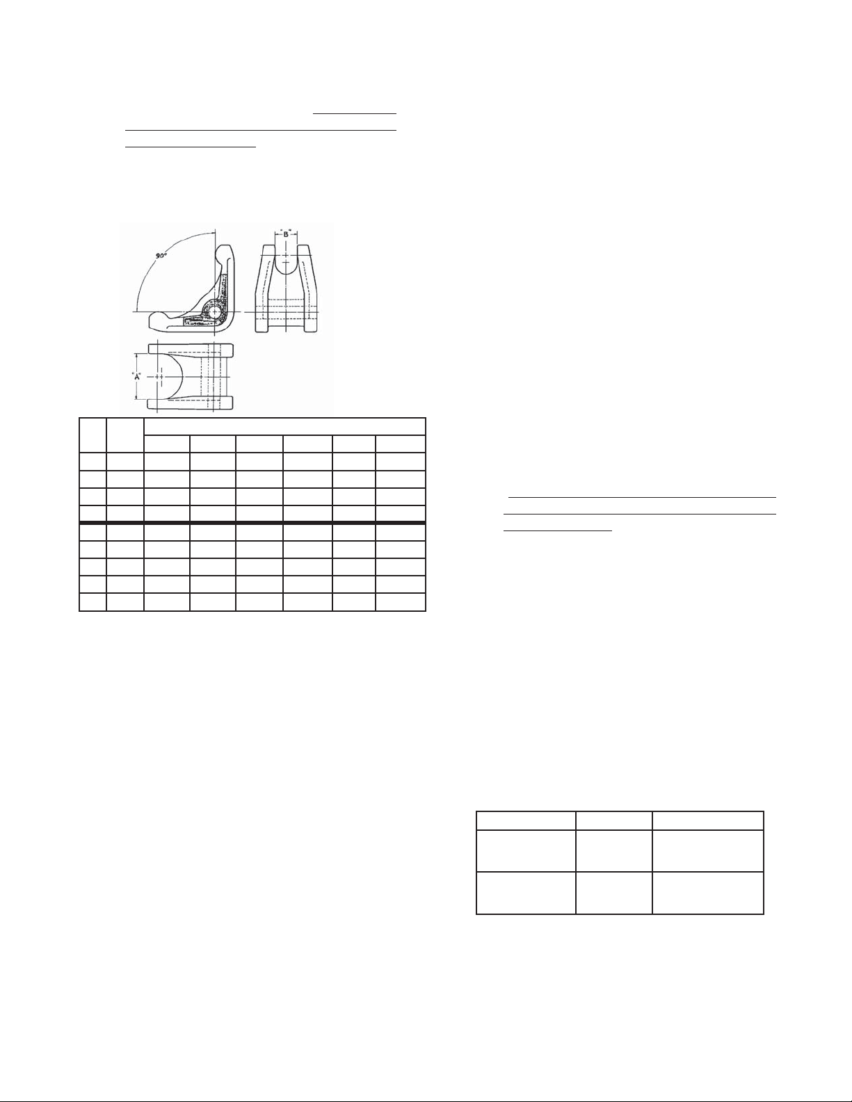
arm (14). Measure inside of rocker arm (14)
“prongs” as indicated below:
DIM MAT'L
A BRZ 7/8" (22mm) 1-5/32" (29mm) 1-7/16" (37mm)
B BRZ 5/8" (16mm) 25/32" (20mm) 3/4" (20mm)
A SST 13/16" (21mm) 1-1/16" (27mm) 1-7/16" (37mm)
B SST 9/16" (14mm) 23/32" (18mm) 3/4" (20mm)
DIM MAT'L 1-1/4" (DN32) 1-1/2" (DN40) 2" (DN50)
A BRZ 1-13/16" (46mm) 1-25/32" (45mm) 2-3/16" (56mm)
B BRZ 29/32" (23mm) 7/8" (22mm) 29/32" (23mm)
A SST 1-1/2" (38mm) 1-25/32" (45mm) 2-5/32" (55mm)
B SST 11/16" (17mm) 7/8" (22mm) 29/32" (23mm)
1/2" (DN15) 3/4" (DN20) 1" (DN25)
Valve Size
If any of the above dimensions are ex ceeded
by 1/8" (3 mm), re place rocker arm (14).
21. Using small gauge wire approximately 18"
(500 mm) long, form a hook and place the
hook over one prong of the rocker arm (14),
and rotate the rocker arm (14) up until slack
is removed in the mechanism. Secure the
wire through a body (1) fl ange bolt hole on
the outlet side of the regulator.
22. Take the diaphragm sub-assembly (Step 16)
and lower it down into the body (1) cavity
off-center approximately 3/4"-1" (20-25 mm)
and to wards the inlet side of the regulator.
When fully low ered, slide the diaphragm subas sem bly horizontally to wards the regulator's
out let. The wire of Step 21 should hold the
rocker arm (14) up to allow engaging of the
pusher plate and stud (13) (with stud nut (10)
and stud collar (16)), so the rocker arm (14)
prongs rest directly on the stud collar (16).
(Do not allow the rocker arm (14) prongs
to get between the stud nut (10) and the
stud collar (16).) Pull fi rmly to remove wire
hold ing rocker arm (14) up.
23. Align diaphragm (20) bolt holes with body (1)
fl ange bolt holes. Set range spring (27) onto
pressure plate (3), place spring button (4) on
top of range spring (27). Place multi-pur pose,
high temperature grease into de pres sion of
spring button (4).
19. Check rocker arm shaft (17) for wear and
straightness. Replace if damaged. Rein stall
in body (1) through rocker arm (14). Apply
thread sealant to the rocker arm shaft (17)
threads prior to tightening. Make sure that
the rocker arm shaft (17) enters the support
slot opposite the threaded open ing, and does
24. Aligning the matchmarks, place spring cham ber (2) over the above stacked parts. Install
all bolts (8), nuts (9) and nameplate (28) by
hand tight en ing. Tighten bolting (8 and 9) in
a cross pattern that allows spring chamber
(2) to be pulled down evenly. Rec om mend ed
torques are as follows:
not align crooked and re strained from full
thread engagement of the rocker arm shaft
(17). Make sure that the rocker arm (14)
prongs that straddle the piston (24) hold the
piston collar (23) against the piston (24); do
not allow the rocker arm (14) prongs to push
directly on the piston (24).
20. Clean the body (1) diaphragm fl ange. Install
a new diaphragm gasket (19). Composition
(soft) diaphragms require no diaphragm gas ket. NOTE: Use only gaskets man u fac tured
by Cashco, Inc., that are of the same ma te ri al
* Minimum recommended torque regardless of gas ket ma te -
ri als. Some gasket materials may require higher bolt torques
to obtain adequate seal.
Gasket ma te ri al may take a “set” with time; a re check of
torques should be made if the unit has been stored on the
shelf for over 30 days.
Body Size Bolt Size All Diaphs.*-Torque
1/2" (DN15)
3/4" (DN20)
1" (DN25)
1-1/4" (DN32)
1-1/2" (DN40)
2" (DN50)
3/8"
7/16"
1/2"
1/2"
9/16"
5/8"
25 ft-lbs. (34 N-m)
35 ft-lbs. (47 N-m)
45 ft-lbs. (61 N-m)
45 ft-lbs. (61 N-m)
80 ft-lbs. (108 N-m)
80 ft-lbs. (108 N-m)
5 IOM-1000HP-Basic
Page 6
NOTE: Never replace bolting (8 and 9) with just any bolting if
lost. Bolt heads and nuts are marked with spec i fi ca tion iden ti-
fi ca tion num bers. Use only proper grades as re placements.
25. Reinstall adjusting screw (6) with locknut
(7); install closing cap (31) if provided.
26. Soap solution test around bolting (8 and 9),
body (1), spring chamber (2) fl anges, and
cyl in der (21)-to-body (1) joint for leak age.
Ensure that an outlet pressure is main tained
during this leak test of at least mid-range
spring level; i.e. 10-40 psig (0.7-2.75 Barg)
range spring, 25 psig (1.75 Barg) test pres sure min i mum. Use 100 psig (7.0 Barg)
min i mum inlet pres sure to leak test. Actual
service con ditions should be used if in ex cess
of the minimum con di tions.
C. Special Instructions for Diaphragm
Removal.
1. If Option 1000-3, Handwheel or Tee-bar, is
uti lized, the adjusting screw (6) and locknut
(7) are replaced re spec tive ly by handwheel/
tee-bar adjusting screw (6) and locking le ver
(7).
2. Use only gaskets of the same material as
those originally utilized. Cashco's Option
1000-45, non-asbestos construction, uti liz es
spe cial gas kets.
D. Diaphragm Setting Adjustment:
1. In the previous “Sub-Section B. Diaph ragm
Replace ment”, care was taken to prevent
re mov al of the stud collar (16) and stud nut
(10). Location of the stud nut (10) is a critical
ad just ment for a Model 1000 regulator.
2. Not removing the stud nut (10) will provide
per for mance equal to original factory per form ance when a diaphragm(s) (20) is re placed
with a like diaphragm(s) (20). How ever, if the
stud nut (10) is removed, or a switch is made
from metal to composition diaphragm (20), or
vice versa, the dia phragm setting should be
checked.
3. Follow procedure “Sub-Section B. Dia phragm
Re place ment” to the point of re mov ing
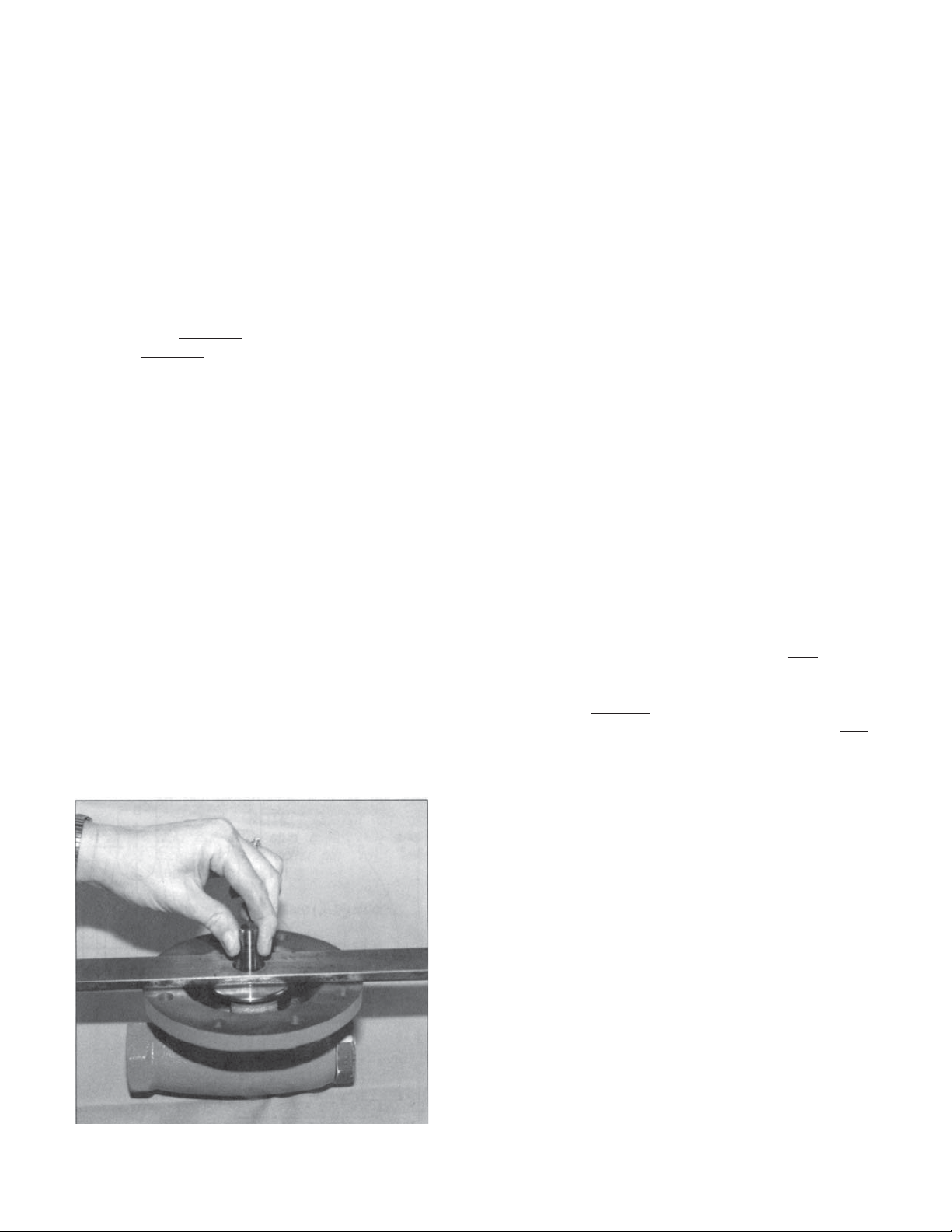
diaphragm(s) (20), Step 14. Remove di a phragm gasket (19) and pusher plate stud
gas ket (12). Obtain a fl at 12" x 1-1/2" x 1/4"
(300 mm x 40 mm x 6 mm) plate bar with a
3/4" (20 mm) hole drilled in the center. Hook
the pusher plate stud (13) into the rocker arm
(14) prongs prop er ly. Pull fi rmly up on the
pusher plate stud (13) to ensure that all slack
is re moved from the mech a nism and that the
piston (24) is seat ed fi rmly. Relax the pulling
and place the fl at bar over the pusher plate
stud (13) with the stud (13) passing through
the hole of the bar. Again, pull fi rmly up to
remove mech a nism slack. One of three positions will be reached:
a. Diaphragm setting too high. Pusher plate
stud (13) will lift the fl at bar over 0.020"
(0.50 mm).
b. Diaphragm setting acceptable. Bar lift ed
be tween 0.010"-0.020" (0.25-0.50 mm).
c. Diaphragm setting too low. Bar lifted less
than 0.010" (0.25 mm), or failed to be
lifted.
4. The castle style stud nut (10) has six lo ca tions
per revolution to align the stud nut (10) slots
with the drilled hole through the pusher plate
stud (13). Each stud nut (10) slot represents
a movement up/down of 0.010" (0.25 mm).
NOTE: The ideal diaphragm set ting is 0.015"
(0.38 mm) high, and better per for mance
is usu al ly obtained when the di a phragm is
slight ly higher rather than low er. As the measuring of thousandths of an inch is dif fi cult with
such a procedure, it is rec om mended that the
“null” position be found where the di a phragm
(20) is fl ush with the body (1) fl ange (bar ap-
prox i mate ly at 0.000" (0.00 mm)). Remove
the push er plate stud (13), rotate the stud nut
(10) one or two slots CCW to bring the setting
to 0.010"-0.020" (0.25-0.50 mm) high.
Checking diaphragm setting.
6 IOM-1000HP-Basic
Page 7
5. Place cotter pin (15) through the slot/hole,
bend over ends.
6. Continue reassembly per Sub-Section B.
Di a phragm Replacement, Step 14.
E. Trim Removal and Replacement
1. Install body (1) horizontally in a vise with the
spring chamber (2) directed upwards, and the
body (1) held at the outlet end.
2. Use a box end wrench or socket, with a lever
length of at least 24 inches (600 mm), and
place it over the hex surfaces of the cylinder
(21). The wrench should be rapped with a
ham mer to loosen.
CAUTION
Take precaution to not allow the piston (24) to fall
from within the cylinder (21); tip cylinder with hex end
down.
3. Continue to unscrew cylinder (21) until re moved. The piston (24) and piston collar (23)
should come out by gravity with the cylinder
(21) removal.
4. If an Option 1000-17 piston spring (30) is utilized, it also should be removed and re placed
at trim replacement.
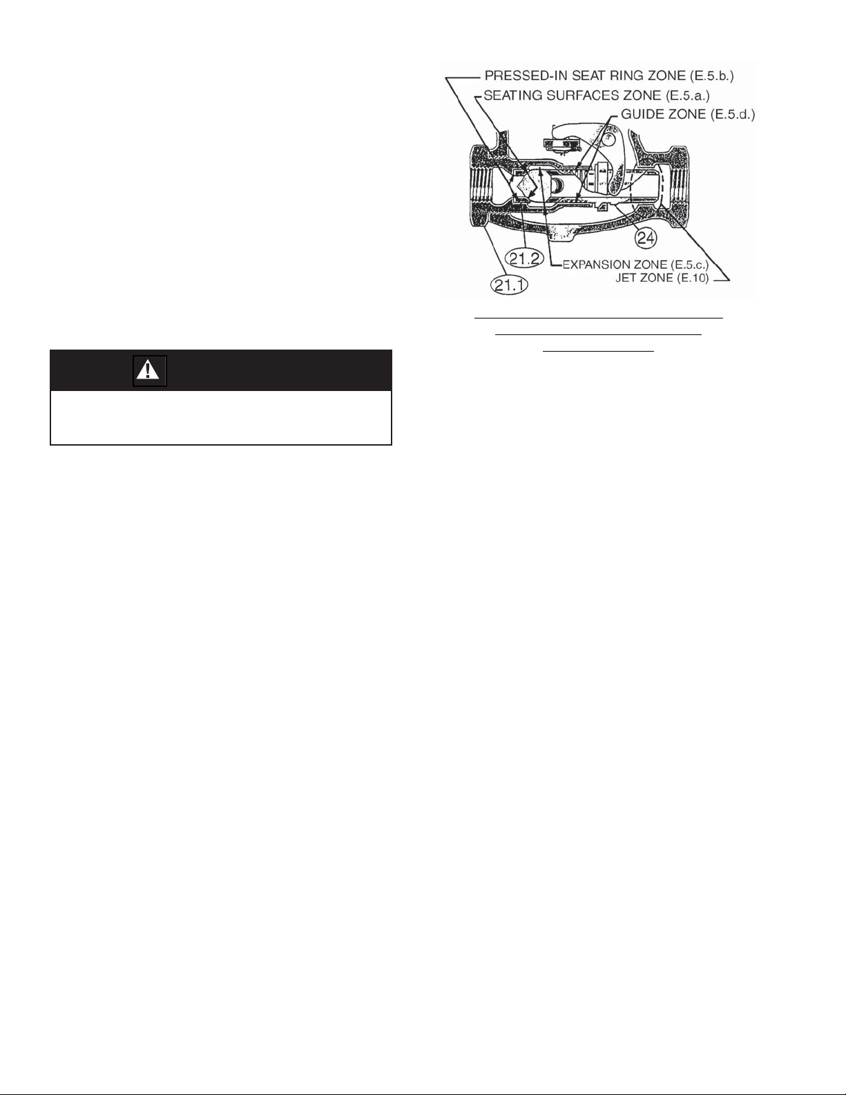
5. Inspect inside surface of cylinder (21) at four
points:
a. Valve seat (21.2). Check for ero sion/
wear on seat ing surfaces. If wear is ex ces sive, con sider utilizing Option 100015, stel lited seat sur faces.
b. Seat (21.2). Check for wire drawing
be tween cyl in der (21.1) and valve seat
(21.2) where pressed in. If wear exists
here, an Option 1000-14, integral seat,
should be utilized as a re place ment.
c. Flow induced wear at expansion zone
where fl uid turns to enter the piston (24)
center.
d. Where the piston (24) ribbed guides bear
(guide zone).
If wear is signifi cant at any of these points,
both cylinder sub-assembly (21) and piston
sub-assembly (24 or 24, 25 and 26) should
CYLINDER SUB-ASSEMBLY (21) WITH
PISTON (24) — METAL SEATED
CONSTRUCTION
be replaced. (Cashco, Inc., does not rec om mend attempting to replace the valve seat
(21.2) by pressing out and then re-pressing
in. Cashco, Inc., also recom mends that a
cyl in der (21) and piston (24 or 24, 25 and 26)
be replaced as a set. Composition seat discs
(25) may be re placed individually.)
6. If a composition (soft) seat trim design is uti lized, use the following sub-steps:
a. Tighten the “fl ats” of the seat disc screw
(26) within a vise. Firmly hand-grip the
piston (24) and turn CCW to loosen the
seat disc screw (26). If too tight, place a
screwdriver or similar rod within the pis ton
(24) port holes and rotate. Remove the
piston (24), and inspect for raised burrs
around the port holes if a device is used
to loosen; deburr as re quired. NOTE: Do
not grip the piston (24) with a wrench.
b. Remove the seat disc (25) and clean the
re cessed piston (24) area where the seat
disc (25) is placed. If the edges which
form the recess of the piston (24) are
worn, also replace piston (24) and seat
disc screw (26).
c. Place seat disc (25) into recessed end of
piston (24).
d. Place thread sealant on threaded por tion
of seat disc screw (26), and manu ally ro tate piston (24) into seat disc screw (26)
(still fi xed in vise) to secure seat disc (25).
Tight en seat disc screw (26) fi rmly. Do
not over-tighten to the point of em bed ding
7 IOM-1000HP-Basic
Page 8
the seat disc screw (26) into the seat disc
(25); the seat disc (25) should lay fl at with
no rounded sur face. A mech anical aid is
nor mal ly not required; hand-tightening is
nor mal ly suf fi cient.
7. If utilized, place piston spring (30) over
small er end of cylinder (21).
8. Insert piston assembly (24 metal seat; 24,
25 and 26 comp. seat) into end of cylinder
(21).
9. Place piston collar (23) over end of piston
(24), ensuring that the spherical surface of
the piston (24) and the piston collar (23) bear
against each other.
10. Clean the body (1) cavity through the open ings. Clean the “jet area” just inside the body
(1) outlet end through which the piston (24)
projects. Clean all parts to be reused. NOTE:
On valves originally sup plied with Option
1000-55, “ox y gen clean”, main te nance must
in clude a level of clean li ness equal to Cashco,
Inc's., cleaning standard #S-1134. Contact
factory for details.
12. Lubricate the cylinder (21) threads lightly with
thread sealant. Insert the entire trim stack
into the body (1) opening and screw until
tightly seated. Using the ham mer and wrench
handle, impact the cylinder (21) into the body
(1). NOTES: 1. Take special pre cau tion to
keep piston collar from getting “cocked” at an
angle when inserted. 2. On 2" brass bodies
(1) with brass trim, a TFE body O-ring (43) is
utilized to seal between the body (1) and the
cylinder (21) sub-as sem bly.
13. Inspect the body (1) outlet end to ensure
that the piston (24) is located nearly concentric to the body (1) bore in the jet area with
clear ance. Under no conditions should the
piston (24) be touching the body (1). Use
two pencils or similar shafts to place in inlet
and outlet ends of regulator and alternately
push on each end of the piston (24) to ensure
free movement. (Total move ment is ap prox i mate ly 1/8" (3 mm).)
14. Bench test unit for suitable operation and seat
leakage. NOTE: Regulators are not nor mal ly
tight shutoff devices. Pressure must build
above setpoint for best shutoff.
11. Use special care cleaning the fl at mating
sur fac es of the body (1) and cylinder (21)
shoulder, as this pressurized joint is metalto-metal with no gasket.
15. Soap solution test around cylinder (21)-tobody (1) con nec tion for leakage. Test pres sure should be a minimum of 100 psig (7.0
Barg) at the inlet, or actual service con di tions
if high er.
SECTION VII
VII. TROUBLE SHOOTING GUIDE
1. Erratic operation, chattering.
Possible Causes Remedies
A. Oversized regulator; inadequate rangeability. A1. Check actual fl ow conditions, resize for minimum and maximum fl ow.
B. Worn piston/cylinder; inadequate guiding. B. Replace trim.
C. Flow induced instability. C1. Get straight runs of piping (5 diameters upstream, 10 downstream)
D. Improper (oversized) jet. D. Replace existing piston with new piston with proper jet.
E. Plugged trim. E. Remove trim and check for plugged holes in piston, or debris in guide
A2. Increase fl ow rate.
A3. Decrease pressure drop; decrease inlet pressure by placing a throttling
orifi ce in inlet piping union.
A4. Replace full orifi ce with reduced orifi ce; i.e. new cylinder required.
to and from regulator.
C2. Ensure outlet velocity is not excessive; use pipe reducer close to regulator outlet.
C3. Add next higher range spring. Contact factory.
C4. If composition diaphragm, switch to metal diaphragm.
zone or jet zone.
8 IOM-1000HP-Basic
Page 9
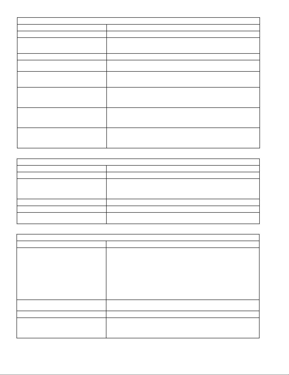
2. Regulator outlet (downstream) pressure too low.
Possible Causes Remedies
A. Setpoint too low. A. Turn adjusting screw down (CW) to increase setpoint.
B. Regulator undersized. B1. Confi rm by opening bypass valve together with regulator.
B2. Check actual fl ow conditions, resize; if regulator has inadequate capacity,
replace with larger unit.
C. Plugged inlet strainer. C. Remove strainer screen and clean; consider leaving screen out.
D. Plugged trim. D. Remove trim and check for plugged holes in piston, or debris in guide
zone or jet zone.
E. Incorrect range spring (turning adjusting
E. Replace range spring with proper higher range. Contact factory.
screw CW does not allow bringing pressure
level up to proper level).
F. Too much droop. F1. Review droop expected. (See 2.B1 above.)
F2. Diaphragm setting too low; check setting and raise as required.
F3. Consider composition diaphragm over metal.
F4. Improper jet; make sure jet matches actual fl uid.
G. Restricted diaphragm movement (pressure
plate hitting upstops)
G1. Diaphragm setting too high; check and lower as required.
G2. Ensure no moisture in spring chamber at temperatures below freeze point.
Ensure no dust or debris entering vent opening. If rainwater or debris can
enter, reorient spring chamber.
H. Restricted diaphragm movement
(overstretched diaphragm).
H1. Diaphragm setting too low; check and increase as required.
H2. Ensure no moisture in spring chamber at temperatures below freeze point.
Ensure no dust or debris entering vent opening. If rainwater or debris can
enter, reorient spring chamber.
3. Leakage through the spring chamber vent hole.
Possible Causes Remedies
A. Normal-life diaphragm failure. A. Replace diaphragm.
B. Abnormal short-life diaphragm failure. B1. Can be caused by excessive chattering. See No. 1 to remedy chatter.
B2. Can be caused by corrosive action. Consider alternate diaphragm material.
B3. For composition diaphragms, ensure not subjecting to over-temperature conditions.
B4. Downstream (outlet) pressure buildup occurring that overstresses diaphragms.
C. Pusher plate gasket leaking. C. Replace gasket.
D. Improper (oversized) jet. D. Replace existing piston with new piston with proper jet.
E. Plugged trim. E. Remove trim and check for plugged holes in piston, or debris in guide
zone or jet zone.
4. Excessive pressure downstream.
Possible Causes Remedies
A. Regulator not closing tightly. A1. Overly compressed range spring; i.e. approaching solid height. Use next
higher range spring.
A2. Inspect the seating. Clean and lap metal seat surfaces; replace if lapping
does not remedy. If composition seats are depressed, nicked or embedded
with debris, replace seat disc.
A3. Diaphragm setting too high; check setting.
A4. Inlet pressure too high for orifi ce size; check permissible inlet (P
level for a given outlet. Change to reduced port if required.
) pressure
1
A5. Leakage past pressed in valve seat ring; consider integral seat.
A6. When diaphragm sub-assembly was put into place, the rocker arm got
between the stud collar and the stud nut rather than on top of the stud collar.
B. Downstream block. B. Check system; isolate (block) fl ow at regulator inlet, not outlet. Relocate
regulator if necessary.
C. No pressure relief protection. C. Install safety relief valve, or rupture disc.
D. Restricted diaphragm movement. D1. Diaphragm setting too high; check and lower as required.
D2. Ensure no moisture in spring chamber at temperatures below freeze point.
Ensure no dust or debris entering vent opening. If rainwater or debris can
enter, reorient spring chamber.
9 IOM-1000HP-Basic
Page 10
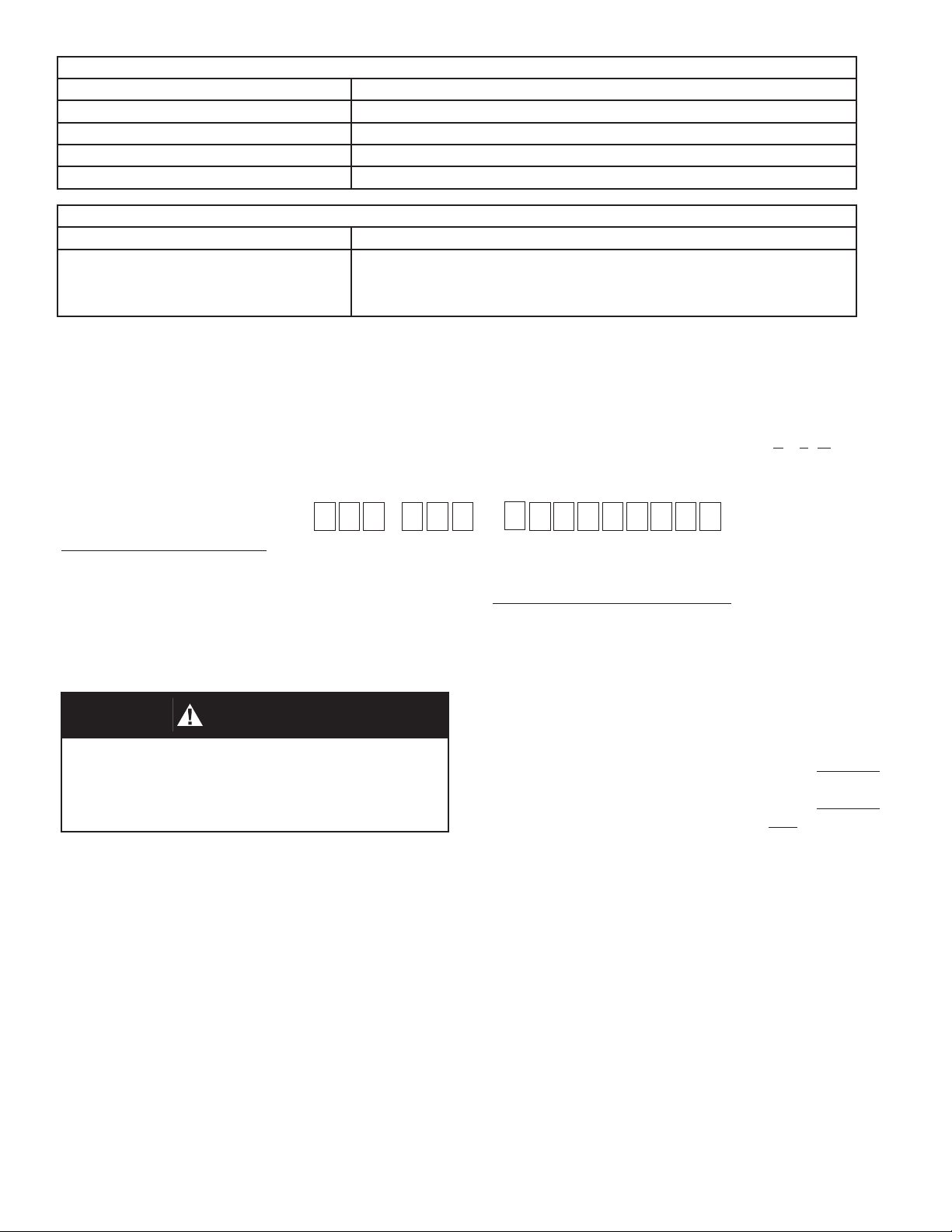
5. Sluggish operation.
Possible Causes Remedies
A. Plugged spring chamber vent. A. Clean vent opening.
B. Plugged piston or jet zone. B. Remove trim and clean.
C. Fluid too viscous. C. Heat fl uid.
D. Improper (undersized) jet. D. Replace existing piston with new piston for viscous service; i.e. Option 1000-27.
6. Frequent resetting of setpoint.
Possible Causes Remedies
A. Over-pressurization downstream resulting in:
1. Bent metal diaphragm(s).
2. Sprung rocker arm.
3. Range spring overstressed/fatigued.
A1. Replace diaphragms. Correct potential source of downstream overpressure.
A2. Check measurements of rocker arm. Replace if necessary.
A3. Replace range spring; consider next higher range spring.
SECTION VIII
VIII. ORDERING INFORMATION
NEW REPLACEMENT UNIT vs PARTS "KIT" FOR FIELD REPAIR
To obtain a quotation or place an order, please retrieve the Serial Number and Product Code that was stamped
on the metal name plate and attached to the unit. This information can also be found on the Bill of Material
(“BOM”), a parts list that was provided when unit was originally shipped. (Serial Number typically 6 digits).
Product Code typical format as follows: (last digit is alpha character that refl ects revision level for the product).
–
NEW REPLACEMENT UNIT:
Contact your local Cashco, Inc., Sales Rep re sen ta tive with the Serial Number and Product code.
With this information they can provide a quotation
for a new unit including a complete description,
price and availability.
CAUTION
Do not attempt to alter the original construction of any
unit without assistance and approval from the factory. All
purposed changes will require a new name plate with appropriate ratings and new product code to accommodate
the recommended part(s) changes.
–
7
PARTS "KIT" for FIELD REPAIR:
Contact your local Cashco, Inc., Sales Rep re sen ta tive with the Serial Number and Product code.
Identify the parts and the quantity required to repair
the unit from the “BOM” sheet that was provided
when unit was originally shipped.
NOTE: Those part numbers that have a quantity indicated
under "Spare Parts" in column "A” refl ect minimum
parts required for inspection and rebuild, - "Soft
Goods Kit". Those in column “B” include minimum
trim replacement parts needed plus those "Soft
Goods" parts from column "A".
If the "BOM" is not available, refer to the crosssectional drawings included in this manual for part
identifi cation and selection.
A Local Sales Representative will provide quotation
for appropriate Kit Number, Price and Availability.
The contents of this publication are presented for informational purposes only, and while every effort has been made to ensure their accuracy, they are not to be construed
as warranties or guarantees, express or implied, regarding the products or services described herein or their use or applicability. We reserve the right to modify or improve
the designs or specifi cations of such product at any time without notice.
Cashco, Inc. does not assume responsibility for the selection, use or maintenance of any product. Responsibility for proper selection, use and maintenance of any Cashco,
Inc. product remains solely with the purchaser.
10 IOM-1000HP-Basic
Page 11

11 IOM-1000HP-Basic
Page 12
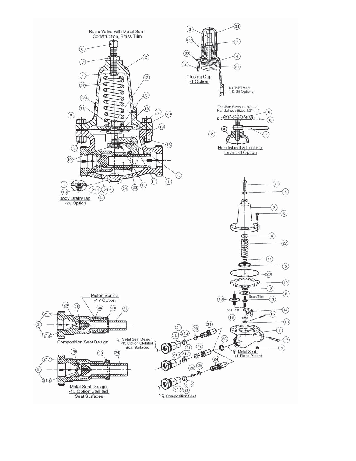
ITEM NO. DESCRIPTION
1. BODY & BODY ASSY
2. SPRING CHAMBER
3. PRESSURE PLATE
4. SPRING BUTTON
5. PUSHER PLATE
6. ADJUSTING SCREW
6. HANDWHEEL ASSY (-3 OPT)
6. TEE-BAR ASSY (-3 OPT)
7. ADJUSTING SCREW LOCK NUT
7. LOCKING LEVER (-3 OPT)
7 SEALING LOCK NUT (-1 OPT)
8. FLANGE BOLT
9. FLANGE NUT
10. STUD NUT
11. PRESSURE PLATE NUT
12. PUSHER PLATE GASKET
13. PUSHER PLATE STUD
14. ROCKER ARM
15. COTTER PIN
ITEM NO. DESCRIPTION
16. STUD COLLAR
17. ROCKER ARM SHAFT
18. BODY PLUG
19. DIAPHRAGM GASKET
20. DIAPHRAGM(S)
21. CYLINDER ASSEMBLY
21.1 CYLINDER
21.2 VALVE SEAT
23. PISTON COLLAR
24. PISTON
25. SEAT DISC
26. SEAT DISC SCREW
27. RANGE SPRING
28. NAME PLATE
29. SEAT CONE (-15 OPT)
30. PISTON SPRING (-17 OPT)
31. CLOSING CAP (-1 OPT)
32. CLOSING CAP GASKET (-1 OPT)
33. SPRING CHAMBER PIPE PLUG (-1 OPT)
Cashco, Inc.
P.O. Box 6
Ellsworth, KS 67439-0006
PH (785) 472-4461
Fax. # (785) 472-3539
www.cashco.com
email: [email protected]
Printed in U.S.A. IOM-1000HP-BASIC
Cashco GmbH
Handwerkerstrasse 15
15366 Hoppegarten, Germany
PH +49 3342 4243135
Fax. No. +49 3342 4243136
www.cashco.com
Email: [email protected]
Cashco do Brasil, Ltda.
Al.Venus, 340
Indaiatuba - Sao Paulo, Brazil
PH +55 11 99677 7177
Fax. No.
www.cashco.com
Email: [email protected]
 Loading...