

Page 1
Casella USA
17 Old Nashua Rd #15
Amherst, NH 03031 USA
TF (800) 366-2966
[email protected]
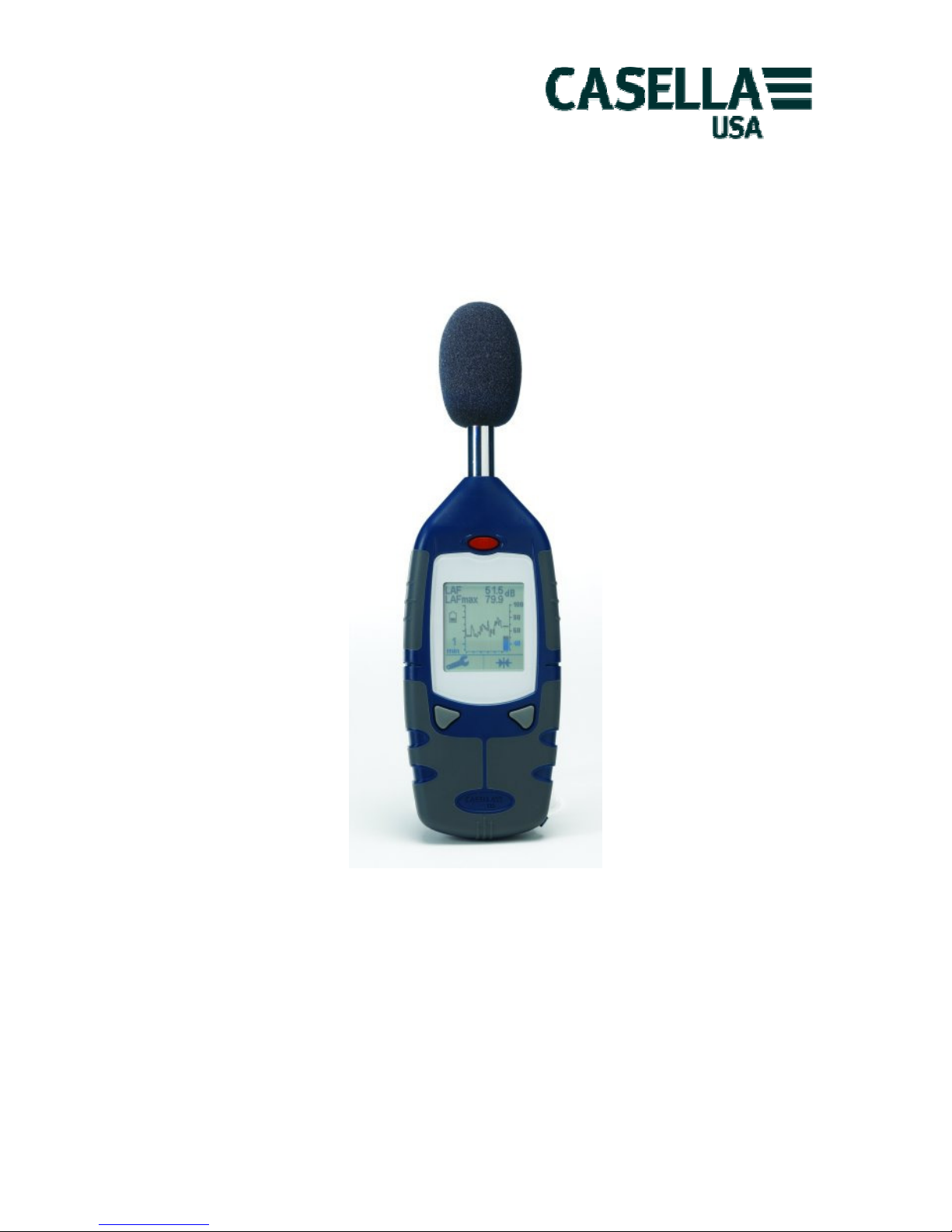
CEL-240 Digital Sound Level Meter
Operator Manual
HB-3331-01
Page 2
Figures
A
B
1
2
3
4 5
1
2
Page 3
C
D E
F G
H I
1
2
4
5
3
6
8
7
1
2
Page 4
J K
CEL -240 Instruction M an ual. H B3331-01 ENGLISH
Digital Sound Level Meter
December 07
Introduction
Con gratulation s on your pur ch as e of the CEL- 24 0 Digi ta l Sound Lev el Me ter. The CE L 240 has been d esigned to perform accurate noise measurements through a wide decibel
range. The CEL-240 is a completely digit a l sound leve l meter, designed fo r stable,
reliable performance, fully complian t with in terna tional sound lev e l meter standards.
This instru c tion man ual is to he lp you get the most ben efi t fro m your CEL- 240 and to
ensure accurate noise measur em ents.
Diagrams
The illu strations and dia grams of the C EL-24 0 instrument and display scre e ns are located
at the beginning of this manual and are referenced in the operation of the instrument
below. Please re fer to the a ppropriat e diagram at th e beg inning of this manual.
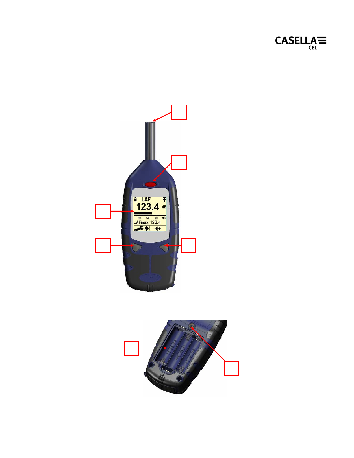
Figu r e A: CEL- 24 0 Figu r e B: Batt er y Com par tm en t
1. Microphone 1. Battery direction
2. Power button 2. ¼” Tripod so cket
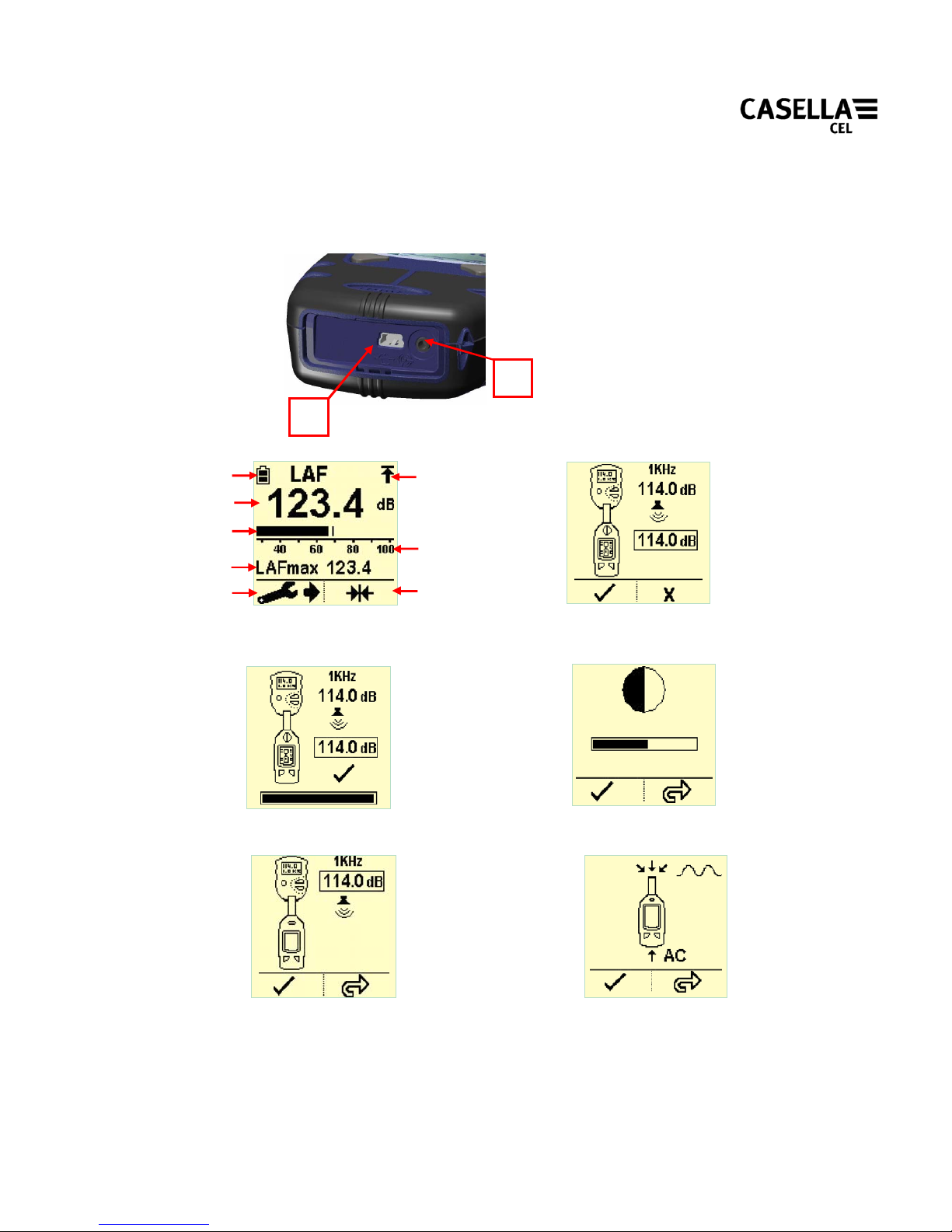
3. Display Figure C: Connections
4. Left key 1. USB Socket
5. Right key 2. Auxiliary socket (2.5mm Stereo)
Figu re D: Displ a y Figu re E: C alib r at ion s cr een
1. Battery ind i cator Figure F: Completed calibration
2. Over range indicator Figure G: Contrast adjustment screen
3. decibel l evel Figure H: Cal ibr at ion lev e l set tin g
4. Analogue display bar Figure I: Source input selection
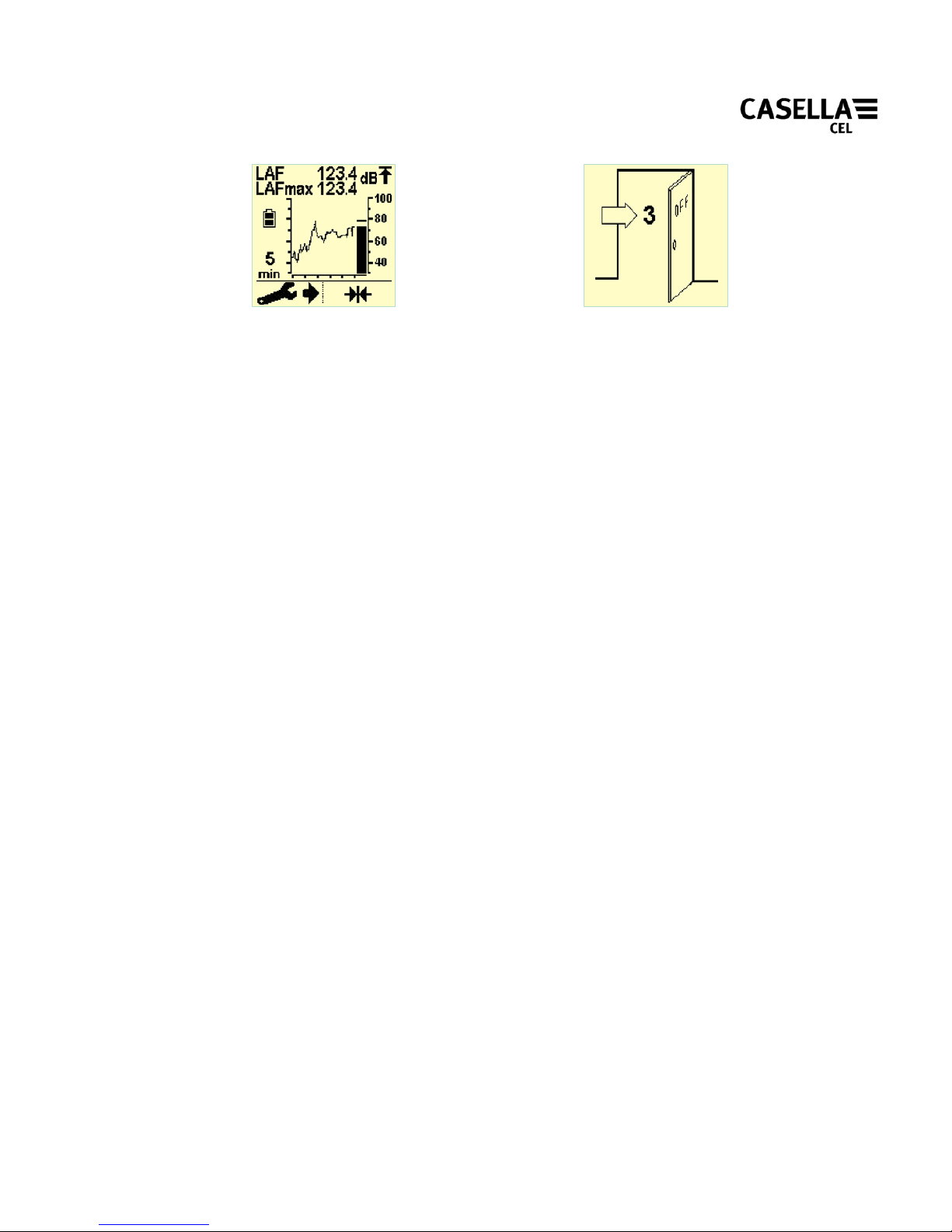
5. Measurement scale Figure J: Time history di splay
Page 5

6. Maximum decibel level Figure K: Power off screen
7. Instrument settings
8. Reset
Preparation for Use
Install three AA Alkaline (or NiMH) batteries observing polarity (Figure B).
Alwa ys r eplace b atteri es when th e b atter y indica tor (Figur e D.1) sho ws the ba tteri es ar e
low to prevent the CEL-24 0 s witching of f during monitorin g.
The CE L-240 is now ready fo r operation.
General Operation
1. Switch on by pressing the power button (Figur e A.2). The instrument displa ys the
firmware version (e.g. v1.01) and serial number (e.g. 0108121) followed by the
mai n measurement screen (Fig ure D).
2. Calibrate the instrument as required. See ‘Calibration’ section.
3. Place the windsh ield ov er the microp hone prior to any measurement.
4. The CEL-240 will display a ba rgraph (Figure D) or tim e histo ry (F igure J)
disp lay. See ‘Instru ment Se ttin gs ’ to chan g e time and freq u en cy wei ght ings, or
type of display.
5. Instantaneous and maximum sound pressure levels are displayed on the
measurement screen with the relevant time and frequency wei ghtin g. The
maximum sound pressure level can be reset by pressing the right key at any
time.
6. Onc e measurements are complete, switch off the instrumen t by holding down the
power key (Figure A.2). The power key needs to be held down for 3 seconds to
preven t accident al switch off.
Calibration
It is recommended that an acoustic calibration is perform ed using a CEL-110/2 or CEL110/1 calibrator before and after measurements as follows:- Switch on the acoustic
calibrator (refer to calibrator instruction manual). If the calibrator has 114dB output,
ensure the CEL-240 is set to the 60-130dB range. Place calibrator firmly over the
microphone.
The CEL-240 automatically detects a 1KHz tone from a 94 or 114dB calibrator and
enters calibration mode (Figure E). Pres s left k ey to perform a calibration or right
key to exit. Upon s uccessful calibration, the scre e n will be as in Figure F.
Instrument Settings
Page 6
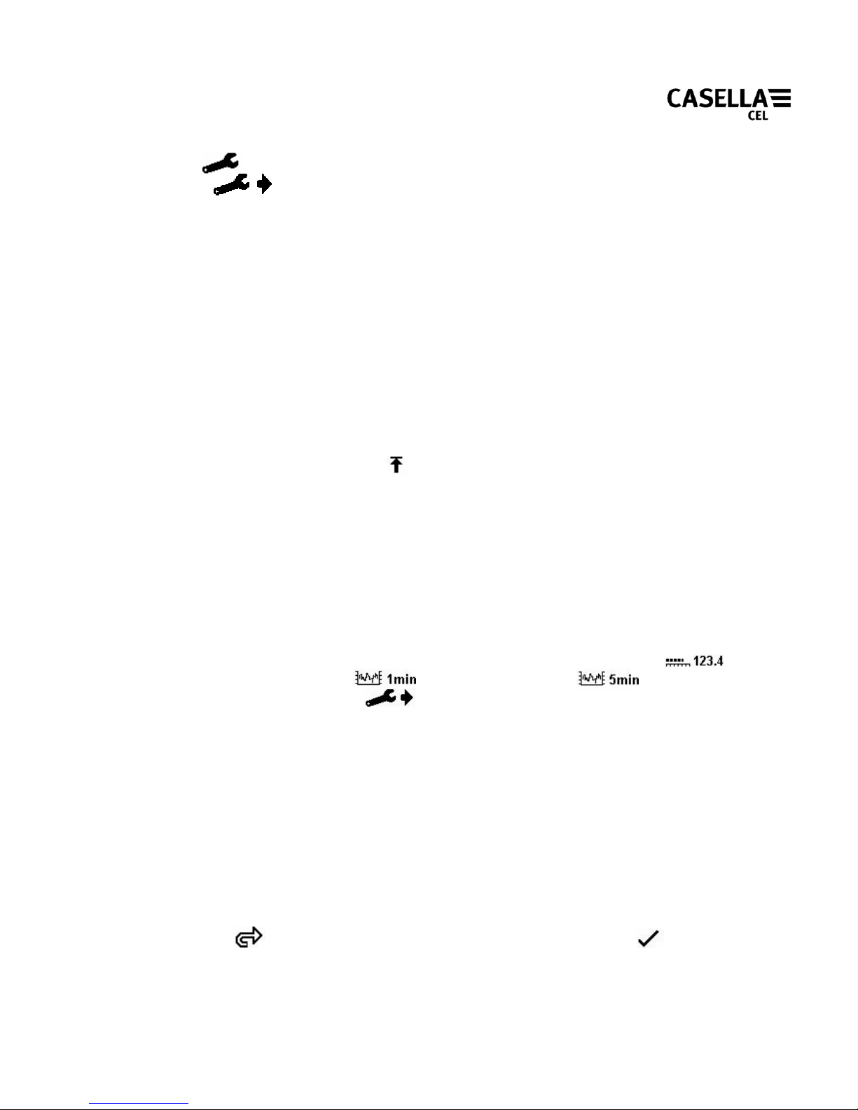
When on the measurem ent screen, settings can be changed using the left key (settings
button) (Figure D.7). Once pressed, an arrow will appear ne x t to the settings
button to show you are in the settings menu. Consecutively pressing the
left button will cycle through setting sc reen s. Press ing the r ight key will make c hanges to
the curr ent s el ec tion . Curren t sett in gs ar e save d when s w i tch ed off.
1. Time weig hti ngs (Fa st, Slow or Impulse)
2. Measurement ra nge ( 30-100dB or 60-130dB)
3. Frequency weightin gs (A or C)
4. Display type, e ither bargrap h or time history grap h (1 or 5 minute time base )
Time wei ghtings: Use Fast response for comparatively stable noise, or select Slow
response for slowly var ying noise. Impulse response may be
selected for more rapidl y varying and impulsive noise.
Measurement range: Care should b e taken to sele ct the correct measurement range
depending on the noise climate being meas ured. Ensu re the n oise
being measu red is within the m eas urement range such th at the over
range indicator is not displayed (Figure D.2). Noise levels
below the measurement range are dis played as ‘--.-d B’
Frequency weightin gs:Frequency weightings are used to represent the human ears
response to noise. The ‘A’ weighting is typically used for general
nois e m easurements. ‘ C’ wei ghting is used at very high noise
levels.
Display typ e: The main display can be changed between a bargraph (Figur e D) to
a tim e history display (Figure J). The time his tory shows how the
maximum sound pressure has varied through either a 1 minute or 5
minute time base. Press the right key to select the bar graph
, 1 minute , or 5 minute t ime history . Pr ess
the left key to confirm the changes and return to the
measurement screen.
Configuration Menu
The configurat ion menu is used to m a ke changes to three sp ecific settings:
• Display contrast
• Calib ra tion lev e l
• Sign al input source
To enter th e configuration menu, hold down the right key when the CEL-240 is switched
off and press the ‘power’ key. The ‘Contrast’ screen is then displayed (Figure G). Press
the r ight key to adjust the contrast as appropriate and then press the left key
to accept the changes.
Page 7
The calibration lev el screen will then be displayed (Figure H) . Thi s screen is used to set
the exac t ref erence level us ed by the acou sti c calib r a tor. Refer to the cal ibra tio n
cert if ic at e f or th e acou s tic calib ra to r for th e cal ibra tor outpu t l eve l.
The ‘Signal input source’ screen (Figure I) will then be shown. NOTE: th is op tion is for
the use of acous tic laboratories only. This allows the signal input to be routed from e ither
the inbuilt microphone or from an external signal generator connected via the auxiliary
2.5m m headphone socket. Press the right key to switch between microphone
input or Alternating Current input . Th e default power up selection
is for mi crophone input. Press the lef t key to confirm any changes.
Specification
General
Designed to provide functio nality wi th re spect to the f ollowing international standards:
IEC 61672-1 2002-5 (Electro-Acoustics – Sound Level Meters) Group ‘X’
instruments, Performance Class 2.
ANS I S1.4 Type 2A Specific at ion for S ou nd Level Meter s
Ran ge : Disp l a y ran g e: 3 0- 130dB(A) R MS, avail ab le in 2 ranges, 30- 10 0d B and
60-130dB. Linear operating range 10dB ab ove noise f lo or.
RMS Frequency Weightings
A and C fi lter weightings, satisfying IEC 61672-1: 2002 Cl ass 2, ANSI S1.4 Type 2A.
Noi se Floor
Total noise floor typically <33dB(A).
Frequency Response
Over all frequency response as per IEC 61672-1: (2002) Class 2, ANSI S1.4 Type 2A.
Time Weightings
Fast, Slow and Impulsive according to IEC 61672-1: (2002), ANSI S1.4 Type 2A.
Reference Conditions
20
o
C air temper ature, 65% Relativ e Hu midity, 101.325kPa atmospheric pressure.
Nominal ref erence level = 114.0dB at 1k Hz. Free field perpendicular incid ence.
Operating Environmenta l Conditio ns
Humidi t y: 5 to 90% RH in th e absenc e of conden sat ion.
Tempera tur e range : 0 to 40
o
C.
Pressure: 65 to 108kPa
Page 8

Effec ts of Humidity: Less than ± 0.5d B over the r ange 30 to 90% r elative
humid ity (non -c o nde nsing ), relat i ve to the value at
reference conditions.
Storage Environmental Conditions
Humidi t y: 0 to 90% RH in th e absenc e of conden sat ion.
Temperature range: -20 to +60
o
C.
Pressure: 65 to 108kPa
Microphone
Internal ele ctret ca psule 10mV/Pa nom +/-3dB within ½” preamplifier.
Calibration
Auto calibration by application of 1kHz @ 114 or 94d B calibrator (CEL-110/2 or CEL110/1 ) . ±1 dB calibrati on range.
Power Supply
External DC: 5VDC (via USB 5 pin m ini B)
Batteries: 3x AA, Rechar geab le NiMH or Alkaline cells
Battery Life: Typically 35 hours
Pow er co ns u mpt ion: ~65mA
Electromagnetic Compatib ility
Instr um en ta tion is des i gned and tested to comp l y with th e followin g EMC and ESD
Standards:IEC 61000-4-2 Testing and Measuring Techniques - Electrostatic discharge
immunity tests.
IEC 61000-4-3 Electromagnetic compatibility (EMC) - Radiated electromagnetic
field tests.
IEC 61000- 4-6 Electrom agnetic compatibilit y ( EMC) - Immunity to conducted
disturbances induced by radio frequency f i elds. Tested at 10V/m or
greater.
Effects of AC Power Frequency Fields
Less than ± 0.5d B ch ange in 74dB(A) 925Hz referenc e level when subjected to 160A/m
AC magnetic field at 50 and 60Hz.
Display
128x128 Mono Graphics LCD, 0. 5 seconds update rate.
Connectivity
US B: USB 2.0 via ‘mini B’ sock et. For SPL output (software required) weighted as per
selected frequency and tim e w eigh tings.
AUX Socket (2.5mm stereo):
Page 9

AC output provided for DAT tape / PC wav file recording or headphone
applications. Approx 0.5V RMS Full Scale Deflection (FSD) ‘A’ w eigh ted output
on selected range. Minimum lo ad impedance 22kΩ. (Optional DC Output via
internal configuration, 0 to 3.3V DC for F SD on selected range. Output
corresponds to selected weighting, 2kΩ Output impedance).
AC input used for electrical calibration, switched on via configur ation menu.
Se rvi c e a nd Wa rra nt y
The man ufactur er und ertakes to rectif y any defe ct in the in strumen t direct ly attribu tab le
to fa ul t y d e s ign or ass em b l y an d wh i c h b e com es app ar ent duri n g the w arr a nt y period . In
order to take advantage of this warranty, the instrumen t must be return ed, carriage paid,
to the manu f actu rer ’s fa ctory or accr ed ited a gent, wh ere ne ce ss ary rep airs wil l be c arri ed
out.
The warranty period runs for 24 months from the date of receipt of goods, with
exceptions on certain specialised com ponents supplied by other manufacturers th at may
be warranted for shorter or longer per iods by their actual manufacturers. In all such cases,
the benefit of th ese undertak ings will be passed on to the user . CASELLA C EL’s l iability
is lim ited to it ems o f th eir own manufactu re, and the y do no t accep t l iabi li ty for an y loss
resulting from the operation or interpretation of the results from this equipment. To
obtain repair under warranty, the instrument should be packed and returned in it’s
ori gina l packing or an equivale nt e ith er to CAS EL LA CEL’s loc al agent, or in the cas e of
U.K. domes tic s ales , to the CASELLA CEL S ervice Depar tmen t at Bedford ., UK. Ple ase
include the following information:
Instrument Typ e(s), Ser ial Number(s) and Firmware Version Number(s), Customer name
and address, Contact name and phone number, details of an y PC and Softwar e involved,
including Version Number(s), reason for returning the equipment with a detailed
descr iption of the f ault and a list of an y e rror m essages that may ha ve b een displayed.
For calibration, service or technical support enquires please con tact :
E-mail: [email protected]
Telephone: +44(0)1234 847777
CASELLA CEL
Regent House,
Wolseley Road,
Kempston,
Bedford,
MK4 2 7 JY, U.K .
Phone: +44 (0) 1234 844 100
Page 10

Fax : +4 4 (0) 12 3 4 841 4 90
E-ma il: info@c ase llace l. com
Web: www.casellacel.com
C AS EL LA USA
17 Old Nashua Ro ad,
# 15, Amherst,
NH 03031,
U.S.A.
Tol l Fre e : +1 (8 00) 36 6 29 66
Fax: +1 (603) 672 8053
E-ma il: inf o @ca se ll aUS A. com
Web: www.casellaUSA.com
CASELLA ESPANA S.A.
Polígono Európolis
Calle C, nº4B
28230 Las Rozas - Madrid
Spain
Pho n e: + 34 91 640 75 19
Fax: + 34 91 636 01 96
E-mail: online@case lla-es.com
Web: www.casella-es.com
 Loading...