

Page 1

CEL-960 Human Vibration Meter
HB4040-01
User Manual
CASELLA MEASUREMENT
Regent House,
Wolseley Road,
Kempston,
Bedford,
MK42 7JY, U.K.
Phone: +44 (0) 1234 844 100
Fax: +44 (0) 1234 841 490
E-mail: [email protected]
Web: www.casellameasurement.com
User Manual
Page 2

CEL-960 Human Vibration Meter
2 Casella CEL
Contents
Contents ........................................................................................................................................... 2
1 General .............................................................................................................................. 5
1.1 Introduction ...................................................................................................................... 5
1.2 Major functions ................................................................................................................. 5
1.3 Displayed Values .............................................................................................................. 6
1.3.1 Measured .......................................................................................................... 6
1.3.2 Additional ......................................................................................................... 6
1.3.3 Alarm indicators ............................................................................................... 6
2 Layout of the CEL-960 Instrument .................................................................................... 7
2.1 Connections ...................................................................................................................... 7
2.1.1 Transducer connector ....................................................................................... 7
2.1.2 Charger / Download connector ........................................................................ 7
2.2 LED’s ................................................................................................................................. 8
2.2.1 Measurement (On/Off) LED .............................................................................. 8
2.2.2 Wireless communication LED ........................................................................... 8
2.2.3 Battery LED ....................................................................................................... 8
2.2.4 Alarm LED ......................................................................................................... 8
2.3 On/Off key ......................................................................................................................... 9
2.4 Charging the battery ....................................................................................................... 10
3 Using the CEL-960 in stand-alone mode .......................................................................... 11
3.1 Introduction ..................................................................................................................... 11
3.2 Calibration of CEL-960 ..................................................................................................... 11
3.3 Measurement mode ......................................................................................................... 11
3.4 Data reading mode .......................................................................................................... 11
4 Using the CEL-960 with a PDA........................................................................................ 12
4.1 Introduction .................................................................................................................... 12
4.2 General operation ........................................................................................................... 12
4.2.1 General points ................................................................................................ 12
4.2.2 Menu bar ........................................................................................................ 13
4.3 Implementation ............................................................................................................... 13
4.4 Main screen ..................................................................................................................... 14
4.4.1 Input of the Licence Number ......................................................................... 14
Page 3

CEL-960 Human Vibration Meter
3 Casella CEL
4.4.2 Creation / Editing / Deletion of a ‘Workshop’ ............................................... 14
4.4.3 Assignment / Removal of a CEL-960 to/from a ‘Workshop’ ......................... 15
4.4.4 Reading / Writing of time and date ............................................................... 16
4.5 Configuration management screen ................................................................................. 16
4.5.1 Measurement configuration screen ............................................................... 17
4.5.2 Start-up configuration screen ........................................................................ 21
4.5.3 System configuration screen ......................................................................... 24
4.6 Measurement mode ........................................................................................................ 25
4.6.1 Measurement screen ...................................................................................... 26
4.7 Measurement stop .......................................................................................................... 29
4.8 Transfer / Deletion of files .............................................................................................. 30
4.8.1 Transfer via Bluetooth ................................................................................... 30
4.8.2 Transfer via USB on PC .................................................................................. 33
4.8.3 Deletion .......................................................................................................... 33
4.9 Reading data stored on the PC ...................................................................................... 34
4.10 Secondary functions ....................................................................................................... 36
4.10.1 Connection ..................................................................................................... 36
4.10.2 Disconnection ................................................................................................. 36
4.10.3 Calibration of CEL-960 ................................................................................... 37
4.10.4 Measurement start ......................................................................................... 39
4.10.5 Measurement stop ......................................................................................... 40
4.10.6 Rename the instrument ................................................................................. 40
4.10.7 Factory configuration ..................................................................................... 40
4.10.8 Auto Test ........................................................................................................ 41
4.10.9 SDCard memory formatting ........................................................................... 42
4.10.10 Reading of transducer characteristics ........................................................... 42
4.10.11 Creating a transducer ..................................................................................... 43
4.10.12 Updating the firmware ................................................................................... 43
5 Using the CEL-960 with a PC .......................................................................................... 45
5.1 Bluetooth communication .............................................................................................. 45
5.2 Launching software dB96 on the PC .............................................................................. 45
5.3 Implementation ............................................................................................................... 45
5.4 Data transfer ................................................................................................................... 46
5.4.1 Data transfer via Bluetooth ........................................................................... 46
Page 4

CEL-960 Human Vibration Meter
4 Casella CEL
5.4.2 Data transfer via USB..................................................................................... 46
6 dB96 System errors ......................................................................................................... 48
7 Technical specifications ................................................................................................... 50
7.1 Standards ........................................................................................................................ 50
7.2 Metrology ........................................................................................................................ 50
7.3 Memory module .............................................................................................................. 51
7.4 Battery ............................................................................................................................. 51
7.5 Physical characteristics ................................................................................................... 52
7.6 Comment on the influence of the electromagnetic environment .................................. 52
8 Maintenance .................................................................................................................... 53
8.1 Auto-Test ......................................................................................................................... 53
8.2 Disposal .......................................................................................................................... 53
9 Icons used in dB96 Control Software ............................................................................. 54
10 Glossary of terms & formulae ......................................................................................... 55
10.1 Terms .............................................................................................................................. 55
10.2 Formulae ......................................................................................................................... 55
Page 5
CEL-960 Human Vibration Meter
5 Casella CEL
1 General
1.1 Introduction
The CEL-960 is a unique concept in the measurement of human vibration since,
unlike other instruments, the person making the measurement can stand remotely
from the subject being monitored and thus not interfere with their work, which
makes it particularly ideal for mobile operatives such as fork lift truck drivers.
It is capable of measuring Hand Arm (HA) or Whole Body (WB) vibration
depending upon the transducer connected i.e. triaxial accelerometer or seat pad, in
either broad band or 1/3rd octaves, again depending whether the latter option has
been purchased.
It meets all the relevant International standards and is further differentiated from
other instruments through it‟s innovative user interface. The CEL-960 has just one
control switch and a small number of LEDs to indicate status, the main control
being performed by software (dB96) which wirelessly connects to the CEL-960 and
runs on a PDA or more typically a laptop PC.
The software allows the instrument to be set up in a so-called workshop, a
measurement to be initiated and results to be viewed in real-time and subsequently
stored. Up to 5 instruments may be controlled in this way. The data may be
downloaded to a spreadsheet or viewed and manipulated in an optional software
package, dB98.
1.2 Major functions
3 Types of measurements:
o Hand arm (frequency) weighted measurements (as per ISO5349 & ANSI
2.70)
o Whole body (frequency) weighted measurements (as per ISO2631 &
ANSI 3.44)
o Unweighted „free‟ measurements
Parallel vibration measurement:
o RMS acceleration: a (x, y, z), aw (x, y, z).
o Peak and peak-to-peak acceleration: apk (x, y, z), awpk (x, y, z).
o Peak factor: fc, fwc.
o Equivalent acceleration: ahv, av, aeq.
Calculation of indicators depending on the configuration:
o A(8), A(8)v.
o VDV, MTVV.
Alarm management:
o Exceeding vibration level threshold.
o Operating status (battery, memory).
Advanced customisation of calculations, display and storage:
o Type of measurement.
o T0: reference duration.
o Integration time.
Page 6
CEL-960 Human Vibration Meter
6 Casella CEL
o Time constant.
o Alarm threshold.
Possibility to program measurement in terms of starting date and duration
(3 different modes):
o Immediate.
o Delayed.
o On a presence detector (with the WB transducer only)
Large storage capacity (1 GB flash memory).
Long battery operating life.
“Bluetooth
®
wireless technology” communication.
Event coding (2 dedicated keys).
Audio recording.
Oral and/or written comments.
Protecting function against accidental shutdown resulting from erroneous
action.
Pre-test function ensuring quick a check-up of operations.
1.3 Displayed Values
1.3.1 Measured
a: Band Pass acceleration
aw: Weighted acceleration (Wd, Wh, Wk filter)
apk: Band Pass peak acceleration
apk-pk: Band Pass peak-to-peak acceleration
apk: Weighted peak acceleration (Wd, Wh, Wk filter)
apk-pk: Weighted peak-to-peak acceleration (Wd, Wh, Wk filter)
fc: Band Pass peak factor
fwc: Weighted peak factor (Wd, Wh, Wk filter)
ahv: Hand Arm resulting acceleration
av: Whole Body resulting acceleration
aeq: Whole Body resulting acceleration
A(8): Hand Arm or Whole Body daily exposure
A(8)v: Whole Body daily exposure
VDV: Whole Body vibration dose
MTVV: maximum transient vibration: maximum value for the mobile RMS
value of the vibration acceleration when the integration time is 1 s.
1.3.2 Additional
Measurement duration
Operating life for measurement
1.3.3 Alarm indicators
Overload and under-load indicator
Alarm indicator
Battery indicator
Page 7
CEL-960 Human Vibration Meter
7 Casella CEL
2 Layout of the CEL-960 Instrument
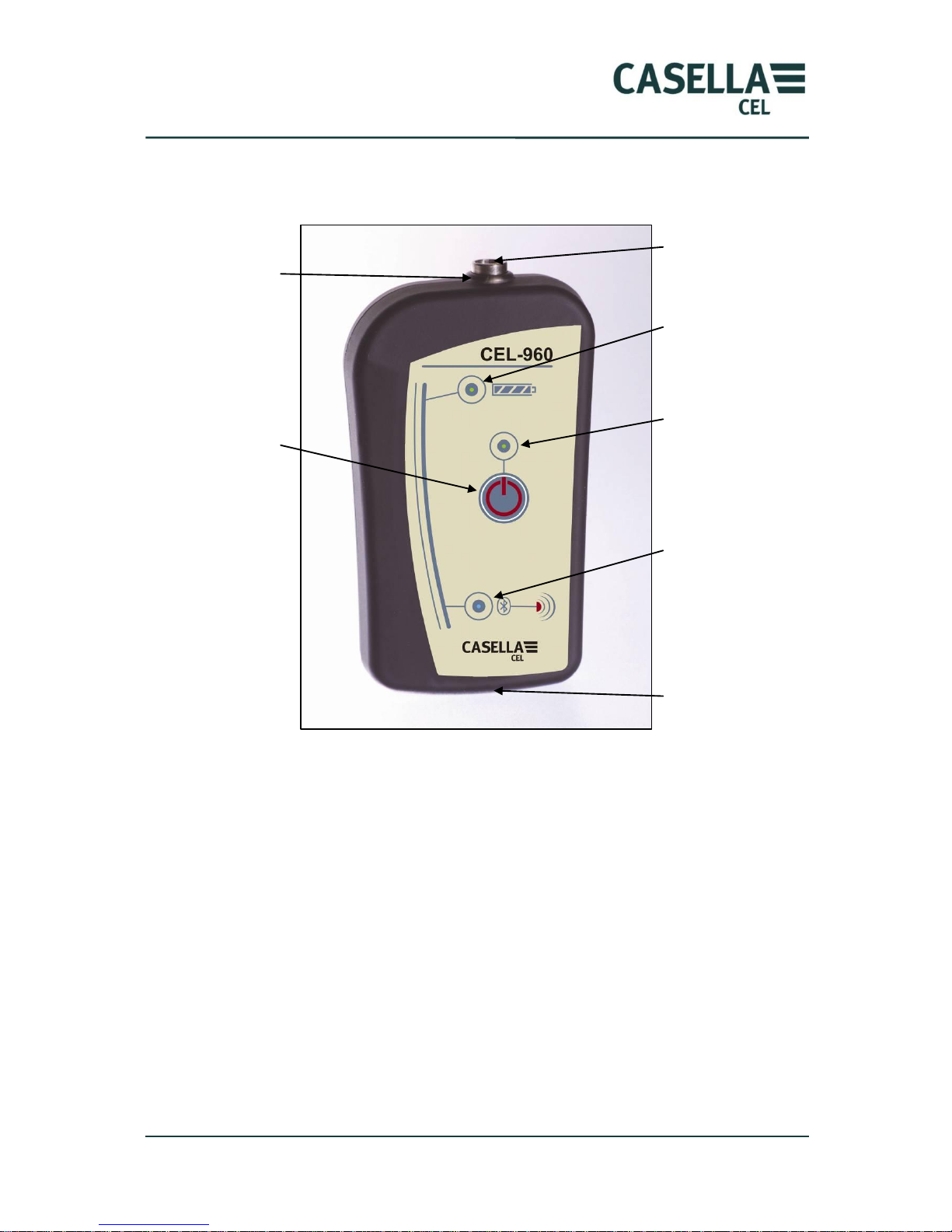
Figure 1. Main features of the CEL-960 Vibration meter
2.1 Connections
2.1.1 Transducer connector
The chosen transducer (HA or WB) is connected via the Lemo connector located on
the top of the instrument. The plug will only fit one way and a red dot on the
connector pair will aid alignment.
In the case of the tri-axial accelerometer, where possible it must be directly attached
to the tool or machine under investigation or alternatively securely attached using
the most appropriate fixing supplied e.g. V-Block and nylon cable ties. If in any
doubt, refer to guidance given in ISO 5349-2 and/or seek advice from a relevant
agency e.g. HSE in the UK, NIOSH in the US.
2.1.2 Charger / Download connector
A USB-type connector is used to charge the CEL-960 with the charger provided (see
section 2.4). It is also be used to read the internal memory.
Connector for HA
or WB transducer
Wireless
communication
LED (displays
Battery LED
(displays red or
green)
USB Connector
(not shown)
Measurement
(On/Off) LED
(displays red or
green)
Alarm LED
(displays
red when
activated)
On/Off key
Page 8
CEL-960 Human Vibration Meter
8 Casella CEL
When the USB connection is active, the Bluetooth communication is disabled.
2.2 LED’s
The LEDs provide information on the operating status of the CEL-960 instrument
as shown in the diagram overleaf. They can be disabled by the PC in order to save
battery life.
2.2.1 Measurement (On/Off) LED
This two-colour green/red LED shows the status of the CEL-960:
Permanently green: instrument is ON.
Fast blinking green: measurement has started.
Green blinking once every second: instrument is in measurement and
storage mode.
Permanently green: displayed at the end of measurement and if
measurement completed correctly.
Permanently red: displayed if measurement stopped abnormally (battery
problem, full memory). See Chapter 6 for details of system errors.
Permanently red (at start): low battery or insufficient memory.
Blinking red: low battery during measurement.
2.2.2 Wireless communication LED
This blue LED shows the status of the wireless connection:
Permanently lit: Bluetooth connection is active.
Blinking: Activity is detected on the network.
2.2.3 Battery LED
CAUTION: this light indicator is the only one that is not managed by the
instruments processor but directly by the charger integrated into the CEL-960
instrument. It lights up as soon as the charger is connected to the CEL-960. It is:
Permanently green during the charging process (turns off at the end of the
process).
Red if charging error (faulty battery, excessive temperature, power supply is
too weak).
2.2.4 Alarm LED
This red LED is located on the top of the housing so as to be visible by the wearer
and shows particular vibration events:
Overload on the input signal of a transducer.
Exceeding a dose or programmed threshold.
Page 9
CEL-960 Human Vibration Meter
9 Casella CEL
At start up, this LED lights up and turns red if the previous measurement stopped
abnormally (full memory or low battery).
During the self test, the alarm LED is on and the red “on/off” LED blinks during the
stabilising phase (10s), then turns green and keeps blinking during the
measurement (5s). This sequence is repeated 4 times.
2.3 On/Off key
This key can be used to trigger several actions depending on the status of the
instrument:
The CEL-960 is “Off”: slightly pressing this key will set the instrument in
stand-by mode, the measurement (On/Off) LED is active and green.
The CEL-960 is “Off”: pressing the On/Off key for about 3 s will set the
instrument in measurement mode (immediate start) with the current
measurement configuration i.e. that stored previously. The measurement
(On/Off) LED lights up permanently from the moment the key is pressed
down, and then blinks rapidly as the measurement starts. During the
measurement, the LED blinks once every second.
If, in the configuration, the LED has been deactivated during measurement, it will
stop blinking after 30 s. Briefly press the key to reactivate the LED for 1 minute.
The CEL-960 is in stand-by mode: press the On/Off key for more than 5s to
stop the instrument.
The CEL-960 is in measurement/storage mode and in discreet mode (the
LED is disabled during the measurement): briefly press the On/Off key to
reactivate the LED during 1 minute.
The CEL-960 is in measurement and storage mode (the Bluetooth
connection is deactivated): press the on/off key for 2 s to reactivate the
Bluetooth communication during 1 minute.
The CEL-960 is in measurement and storage mode (non deactivated key):
press the On/Off key for more than 10s to stop the instrument.
The CEL-960 is in measurement/storage mode: pressing the On/Off key will
have no effect if the key has been deactivated. In order to stop the
measurement, one must take control using the PC or wait for the battery to
be discharged or for the measurement to be completed if automatic stop has
been programmed. However, pressing the On/Off key 10 times with the
same frequency as that of the blinking of the green LED will stop the
instrument.
When the CEL-960 is shut down, the Alarm LED blinks red for 5 seconds. Pressing
the key for 2 seconds will reactivate the Bluetooth connection during 5 minutes,
thus allowing taking control of the instrument with a PC.
Page 10

CEL-960 Human Vibration Meter
10 Casella CEL
2.4 Charging the battery
When the battery is low, the On/OFF LED lights up in red, meaning that the battery
needs to be recharged.
Also, if when sending out a measurement configuration, the end date and time for
the measurement do not correspond to those expected and if the available memory
size is large enough, the battery needs to be recharged. To do so, connect CEL-960
to the charger base. The Battery LED lights up in red upon connection, then turns
green indicating that the charging process has started and is in progress.
After 3 hours, the charging is finished and the Battery LED turns off: the battery is
now correctly charged.
It is also possible to charge the battery using the USB cable but the charge may be
incomplete. This results from the voltage drop in the cable, which varies depending
on the cable. If the charging process is not completed after 7 hours, the LED will
light up in red.
If the battery is already charged when it is connected to the charger, the LED will
light from red to green and then turn off after a few minutes.
If the LED remains permanently red it means that a problem was detected during
the charging process. It may be an abnormally discharged battery, which cannot
then be recharged, or a charge voltage that is too low, or excess battery heat-up.
Page 11
CEL-960 Human Vibration Meter
11 Casella CEL
3 Using the CEL-960 in stand-alone mode
3.1 Introduction
Although the CEL-960 has been designed to be operated coupled with a PDA or PC
that acts, as the user interface, it can be used in stand-alone mode. In this case, the
CEL-960 can perform measurements and store them, according to the
measurement configuration previously used.
The key on the front panel is used for:
Power up
Immediate start of the measurement
When the CEL-960 is powered up, the “On/Off” LED lights up in green if the
instrument does not detect any operating defect. If a problem is detected when the
instrument is started, the LED lights up in red indicating that a problem was
encountered. The measurement will not start until the problem is resolved.
The “Battery” LED remains off as long as the battery has not reached its recharging
threshold and can thus still perform measurements for some time.
3.2 Calibration of CEL-960
No calibration can be performed in the stand-alone mode. A PC is required for this
operation.
3.3 Measurement mode
Pressing the « On / Off » key for 5 seconds will start the measurement. The LED
blinks rapidly while the CEL-960 stores values defined in the configuration
memorised last, according to the defined integration time. After a time out of 10 s
(stabilisation time for the measurement system), the green LED (on/off) blinks once
every second, indicating that CEL-960 is in measurement and storage mode.
The measurement stops:
By pressing (10s) on the « On / Off » key
When the battery is empty
When the memory is stopped
When the measurement is stopped using the keyboard, the « On / Off » LED blinks
red for 5 s before stopping of the instrument.
Even if the instrument stops the measurement after detecting low battery or full
memory, the measurement file is still closed before shutdown.
For this type of operating mode (start from the keyboard), the time start
configuration is ignored.
3.4 Data reading mode
In stand-alone mode, data must be transferred to the PDA or to a PC for further
analysis. Please refer to Chapters 4 & 5.
Page 12
CEL-960 Human Vibration Meter
12 Casella CEL
4 Using the CEL-960 with a PDA
4.1 Introduction
This is the most advanced operating mode for the CEL-960, which gives it
unrivalled power and user-friendliness required to study occupational vibration.
The PDA is used to set up the CEL-960 in a „workshop‟, then to monitor up to five
instruments simultaneously.
A full list of icons used is shown on Section 9.
Where a PC is used instead of a PDA, please refer to Section 5, which shows the
differences in operation.
4.2 General operation
4.2.1 General points
The different icons are as universal as possible and all basic actions can be accessed
directly from each screen. Only functions that are specific to a particular instrument
require a specific action: use of the stylus on the area representing the instrument.
This can be compared to the “right click” of a PC mouse.
A keyboard is displayed at the bottom of the screens where text input is possible.
The user can enter the text using the stylus. Clicking on the keyboard icon
will show or hide the keyboard.
In the list of CEL-960s assigned to a „workshop‟ (right side of the screen), an
instrument icon is displayed and information corresponding to this instrument
is also displayed i.e. the serial number.
On the virtual keyboard, one can switch from the alphabetic to the numeric
keyboard by clicking on the key.
Page 13
CEL-960 Human Vibration Meter
13 Casella CEL
4.2.2 Menu bar
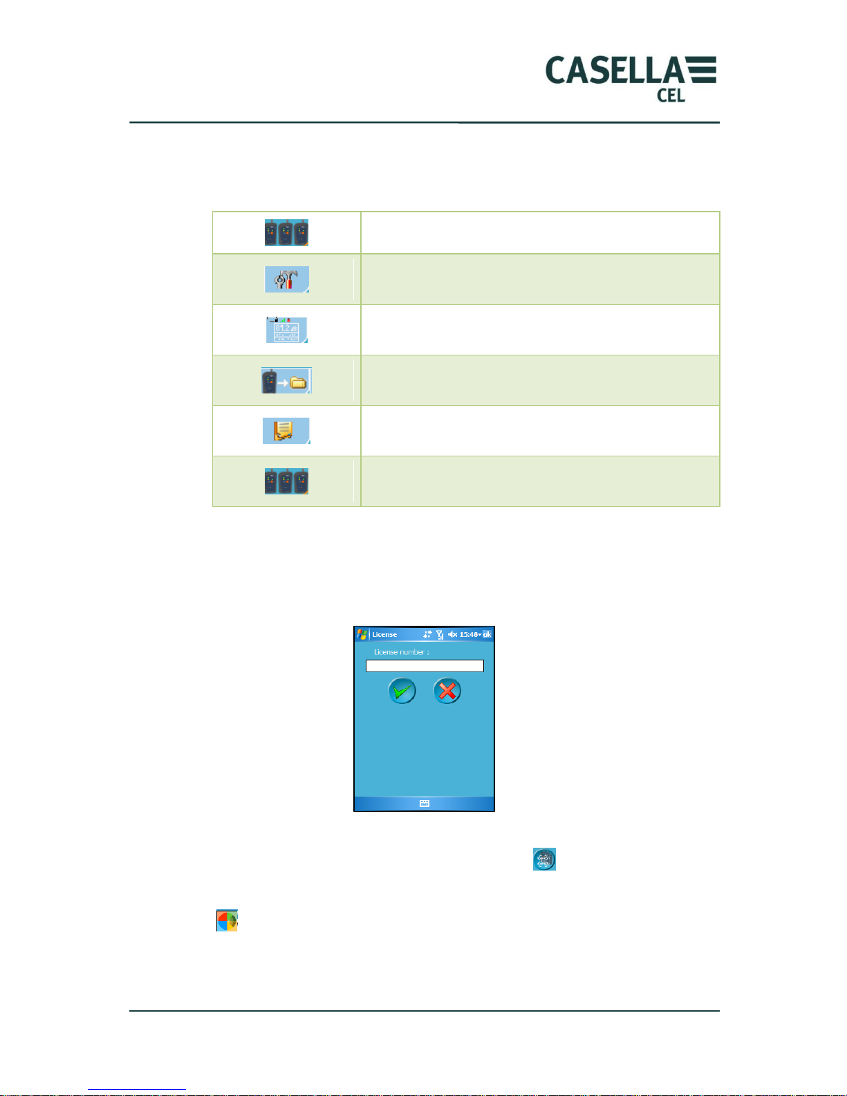
This bar, which is displayed in all screens, is used to switch rapidly from one screen
to another.
Access to „workshop‟ management
Access to measurement and storage parameters
Access to real-time display of vibration indicators
F (fast), S (slow)
Access to data transfer function from CEL-960 to the
PC
Access to results screen
4.3 Implementation
When the software program is started for the first time, the user is prompted for a
licence number, which will allow unlocking operating modes and options. The
software will not operate without this number.
After launching the dB96 program, the user must „search‟ for the CEL-960(s)
present in the wireless communication range using the key.
The communication range is about 10 m for a PDA equipped with class-2 Bluetooth.
Icon shows this activity. When this implementation phase is finished, the
„workshop‟ management screen is displayed.
Page 14
CEL-960 Human Vibration Meter
14 Casella CEL
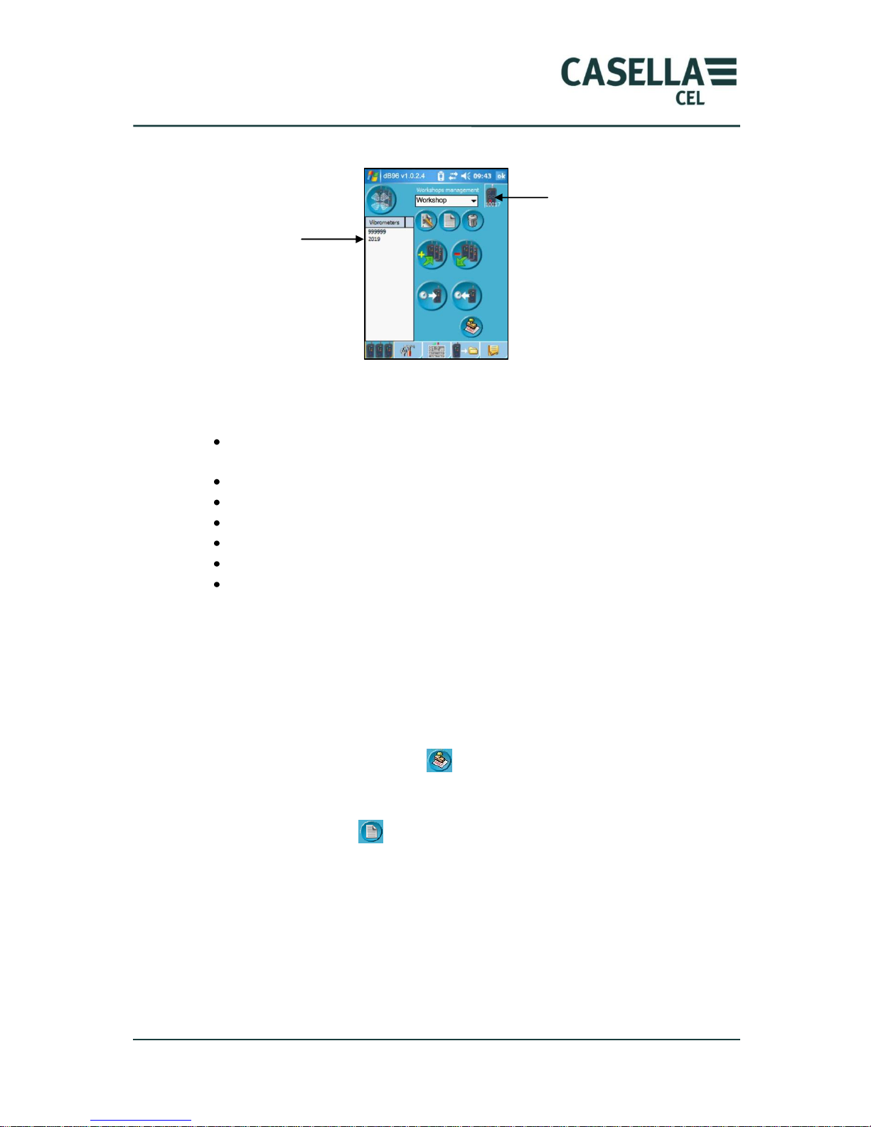
4.4 Main screen
This screen is used to organise measuring instruments based on the operator‟s
requirements:
Assignment of a name to a „workshop‟ when it is created and input of a brief
description.
Deletion of a „workshop‟ from the list.
Assignment of 1 to 5 CEL-960s to the „workshop‟.
Deletion of one or several CEL-960s from the „workshop‟.
Reading of the date and time of a CEL-960 instrument.
Date and time setting of all CEL-960 instruments in the „workshop‟.
Input of the licence number.
The left part of the screen shows the list of instruments that can be assigned to the
„workshop‟ (this list is built up as CEL-960 instruments are detected in the
immediate surroundings of the PDA). Already assigned instruments are listed in the
right part of the screen.
4.4.1 Input of the Licence Number
The operator must first enter the licence number corresponding to the options
available on CEL-960 by clicking on .
4.4.2 Creation / Editing / Deletion of a ‘Workshop’
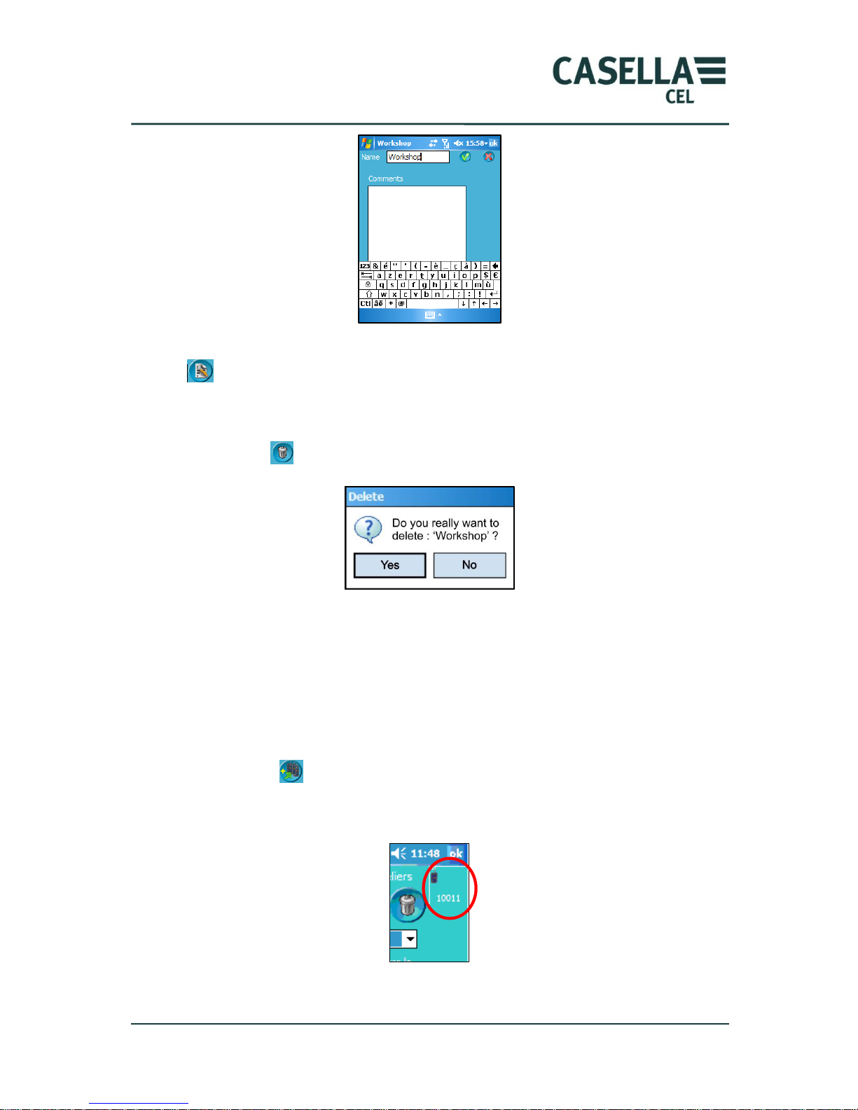
Click on the creation icon to create a new „workshop‟. An input keyboard is
available at the bottom of the screen. The operator can enter the name of the
„workshop‟ and add a comment, e.g., a technical description.
Instrument
10017 is
assigned to
the workshop
2 CEL-960 are
detected and
waiting to be
assigned
Page 15
CEL-960 Human Vibration Meter
15 Casella CEL
This keyboard is also available when an existing „workshop‟ is edited by using icon
. When the input or the editing is finished, the operator selects the validation
icon or the cancellation icon to quit this screen without the changes.
A „workshop‟ can be deleted from the list by displaying its name in the window and
selecting the icon. A confirmation is always requested to avoid any error.
Creation, editing, deletion procedures are the same for all screens („workshop‟,
configuration).
4.4.3 Assignment / Removal of a CEL-960 to/from a ‘Workshop’
Once an instrument is selected in the list on the left (click on the CEL-960 serial
number to select it), the operator can assign the instrument to a „workshop‟ as
follows:
Selecting icon will transfer the selected instrument from the list on the left to
the „workshop‟, the name of which is displayed (list in top right corner of the
screen).
Page 16
CEL-960 Human Vibration Meter
16 Casella CEL
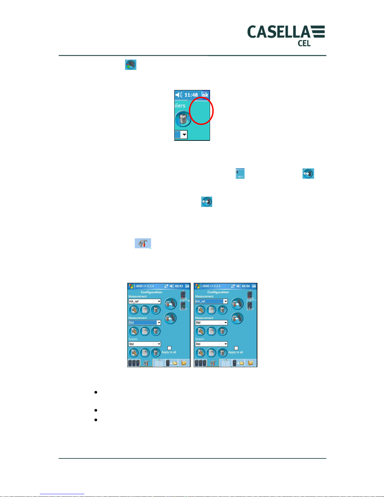
Selecting icon will remove the selected instrument from the „workshop‟ and
place it in the list on the left. CEL-960 no longer appears on the top right of the
screen.
4.4.4 Reading / Writing of time and date
At any time, the operator can read the date and time of the selected CEL-960
instrument exposure meter, which is marked by icon , by clicking on icon .
Before starting a measurement, the operator can even send the date and time of the
PC to all Instruments by clicking on icon .
4.5 Configuration management screen
The configuration of the CEL-960‟s assigned to the „workshop‟ is achieved from this
screen using icon .
User-selected parameters are then transferred to one or several instruments. The
user can also retrieve the internal configuration of a selected instrument.
The user can create, edit or delete 3 types of configurations:
The measurement configuration (3 types of measurements are possible:
whole body, hand arm, free).
The start-up configuration.
The system configuration.
Editing, creation and deletion icons perform the same functions as those in the
„workshop‟ screen.
Page 17
CEL-960 Human Vibration Meter
17 Casella CEL
4.5.1 Measurement configuration screen
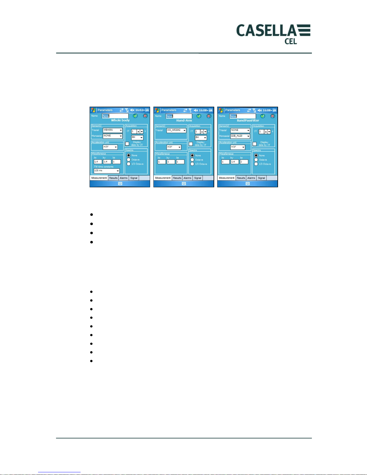
Suited to the CEL-960 operating mode (whole body, hand arm, free), this screen is
more or less detailed depending on the presence of the audio and spectrum option.
Some of these screens below are only available in CEL-960 Expert.
The “Measurement configuration” screen includes several tabs:
Configuration of the measurement.
Configuration of displayed and stored overall results.
Alarm configuration.
Configuration of the sampled signal recording (option).
4.5.1.1 Configuration of the measurement
This configuration of the parameters of the instrument allows selecting, depending
on the type of measurement:
Type of accelerometer.
Measurement unit.
Coefficients used in the calculation of indicators av, ahv.
Integration time.
Time constant.
Standardised duration T0 for the work station.
Real-time display frequency for indicators.
Channel and type of filtering (octave, 1/3 octave) on this channel (option).
Limits of the analysis band in free mode
The Time constant parameter is only used in the whole-body measurement, in
indicator MTVV.
The signal recording channel must be the same as the spectrum calculation channel.
If box “Display at IT” is checked, results are refreshed every integration time,
otherwise every second.
Page 18
CEL-960 Human Vibration Meter
18 Casella CEL
If the keyboard hides the table bottoms, the user can click on the keyboard icon
, so that the keyboard is minimised and the hidden parts are shown.
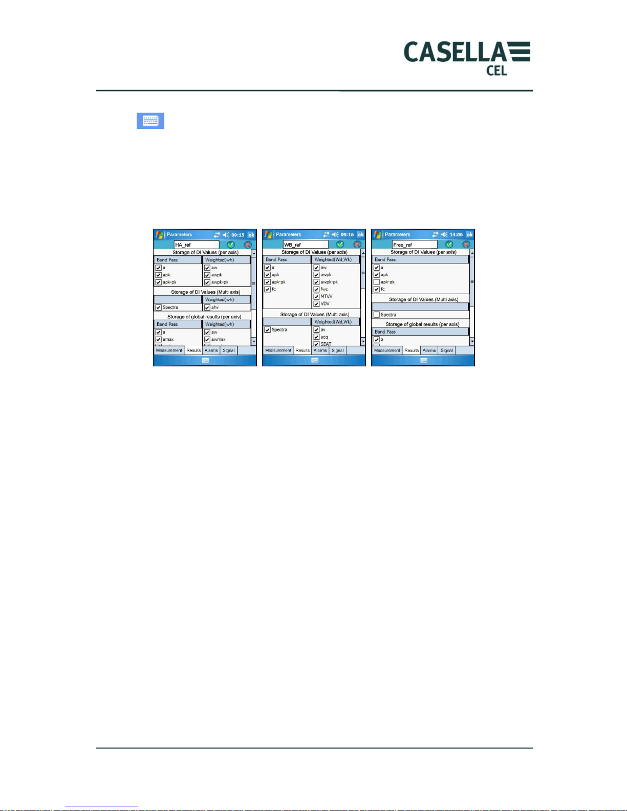
4.5.1.2 Configuration of measurement results
This part of the measurement configuration allows the operator selecting only
results that he/she wants to see displayed and stored.
This confirmation is confirmed by clicking on the validation icon.
Storage of IT per axis: RMS and peak values stored at each integration time,
either in “broad band”, or weighted.
Storage of multi axis IT: Values resulting from calculation over the 3 axes and
stored at each integration time.
Note: the spectrum is calculated on a single axis.
Storage of global results per axis: Global values calculated on each axis, over
the total measurement time.
Storage of global multi axis results: Values calculated over the measurement
time and taking into account the 3 measurement axes.
At the end of the measurement, only selected indicator will be displayed on and
stored in the PC as a text file.
4.5.1.3 Configuration of alarms
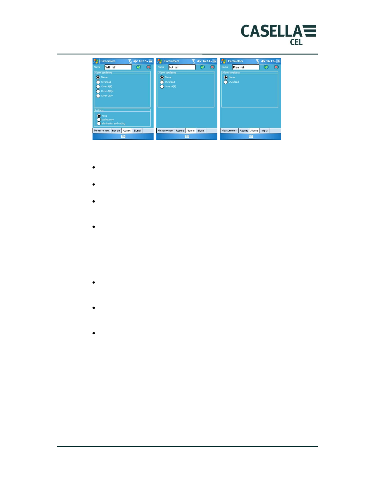
The Alarm LED will be triggered if one of the conditions presented below is fulfilled.
These conditions are different depending on the type of measurement: whole body,
hand arm or free.
If the operator decides not to set any alarm condition, the option “Never” must be
selected.
Page 19
CEL-960 Human Vibration Meter
19 Casella CEL
The different triggering options are as follows:
Overload: as soon as the vibration signal overloads, CEL-960 indicates it by
activating the LED.
Exceeding A(8): as soon as the exposure level A(8) is exceeded, the alarm
LED is activated.
Exceeding A(8)v: the LED is activated as soon as the A(8)v level is exceeded.
This alarm exists only for whole body measurements. Please refer to the
definition of A(8) and A(8)v for more details.
Exceeding VDV: the operator can request the activation of the LED when
VDV exceeds the alarm level.
In case of a whole-body measurement and when using the seatpad transducer
(equipped with a presence detector (see section 7.2.), this screen allows selecting
the operating mode for the detector:
None: the operating mode does not take the presence detector into account.
This option is selected if one does not want to use this detector or if the
transducer is not equipped with this detector.
Coding (Marking of data): if this option is selected each time the presence
detector is no longer active (i.e., the operator leaves the seat or if he/she
stands up) recorded data will be coded (marked).
Deletion and coding: if this box is checked, the non presence of the operator
on the seat will lead to the coding of stored values and the affect acquired
data.
In this case, the real-time results screen will display the calculation time in addition
to the measurement time. It corresponds to the total measurement time minus the
periods of non presence of the operator on the seat.
The artefact counter (non presence of the individual on the seat) is incremented
every second.
Page 20
CEL-960 Human Vibration Meter
20 Casella CEL
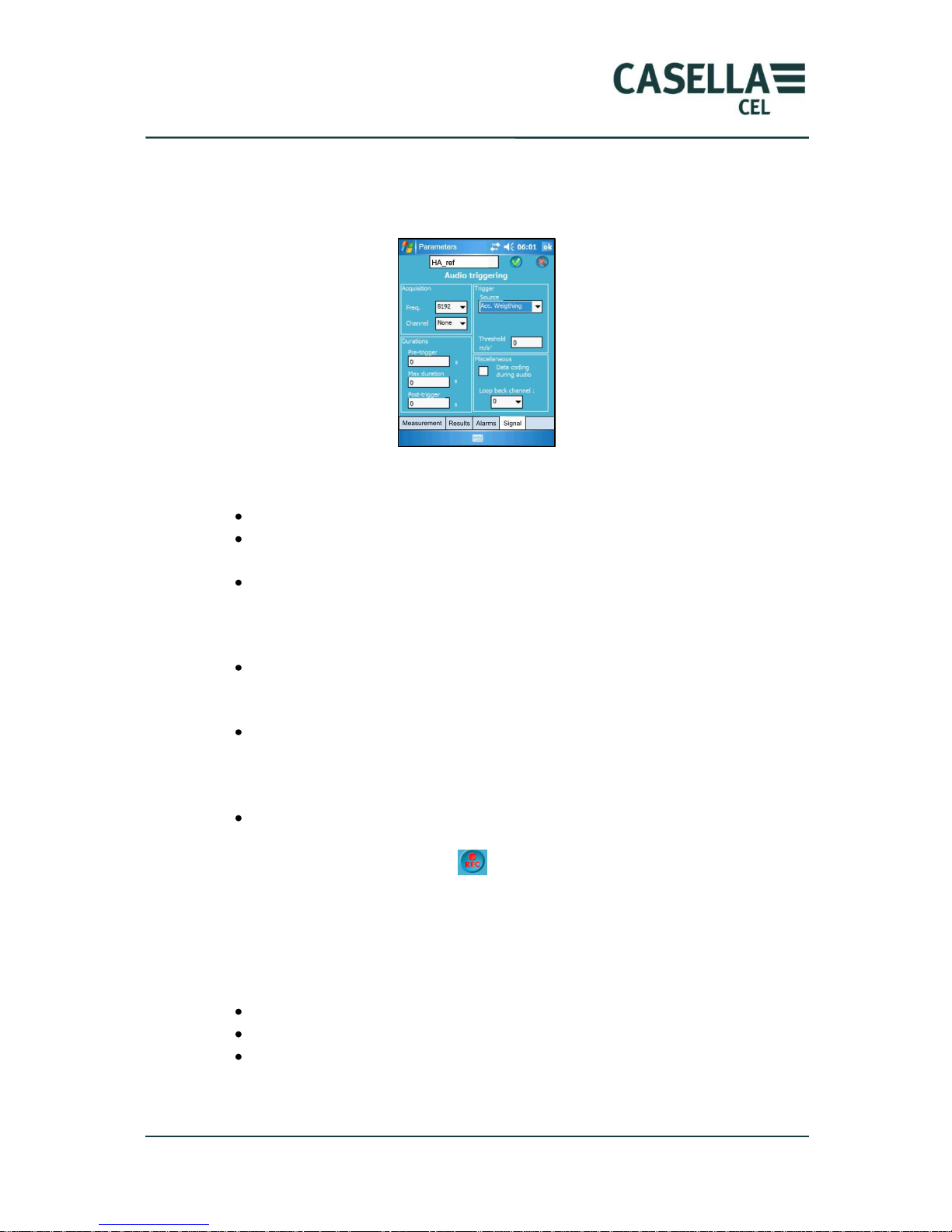
4.5.1.4 Configuration of the audio recording (option)
The recording of the vibration signal is an option that is available in whole-body,
hand-arm and free mode.
In the configuration screen, the operator can select:
The sampling frequency ranging from 256 Hz to 8192 Hz.
The acquisition channel: the signal can only be recorded for the channel
used to calculate the spectrum.
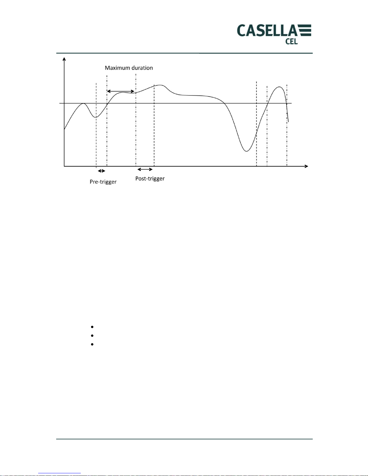
The pre-trigger time, which is the time before the event recorded when the
recording is triggered on threshold. The maximum value of the pre-trigger
depends on the calibration frequency: 0 s for 8192 Hz, 1 s for 4096 Hz…. 16 s
at 256 Hz, etc.
The post-trigger duration: when the recording of a signal is triggered on
threshold after the values goes below the threshold, the signal keeps being
recorded during this time.
The maximum recording time: the recording time is limited to a maximum
value in order not to fill the memory. This means that if one selects 20 s and
if the threshold exceeds 5 minutes, the maximum recording time will be the
pre-trigger duration + 20 s + the post-trigger duration.
The triggering type:
o Manual: The operator activate the signal recording, according to its
needs (click on icon ).
o On limit value: As soon as the programmed limit value is reached,
the recording is activated or stopped, taking into account the pretrigger/post-trigger parameters and the maximum duration.
The limit value can be chosen on:
Band pass (unweighted) acceleration.
Acceleration with Wh, Wd, Wk frequency weighting.
A spectrum band 1/1 octave or 1/3 octave if a spectrum is selected in the
measurement configuration.
Page 21
CEL-960 Human Vibration Meter
21 Casella CEL
A new trigger is allowed only after a threshold is exceeded.
The channel for signal recording has to be the same as that for spectrum
calculations.
When recording the signal either manually or on threshold, the internal memory is
allocated as follows:
o 50 MB for time data
o The remaining memory is kept to store the signal.
When the 50 MB allocated for the storage of time data is reached, another 50 MB is
taken from the signal storage area and re-allocated to data storage.
4.5.2 Start-up configuration screen
In this part of the configuration, the user can program the name of the
configuration, the date and time for measurement start and its duration. 4 types of
starts are available depending on the selected strategy:
Immediate start of the measurement.
Delayed start.
Start on detection of presence (WBV only).
Whatever the type of start, the operator can name it using the keyboard. This name
will be used to find the selected configuration among all stored configurations.
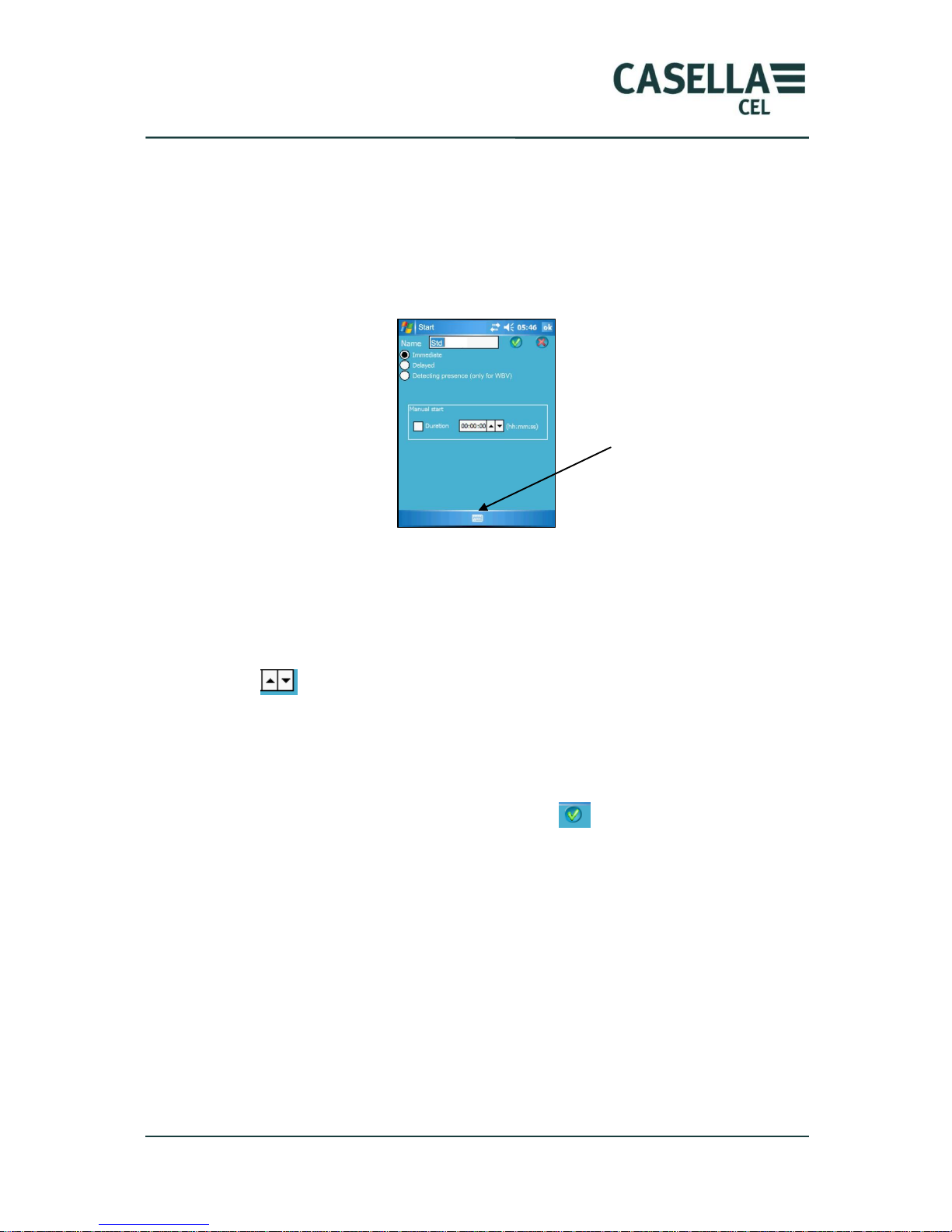
The virtual keyboard is shown or hidden by clicking on the icon at the bottom of the
screen..
The presence detector is used to start or stop the measurement. To this aim, the
user will program a minimum presence duration after which the measurement will
start : the operator must be seated for, e.g., 10 s, for data storage to start and leave
the seat for 5 minutes for CEL-960 to stop data acquisition.
Page 22
CEL-960 Human Vibration Meter
22 Casella CEL
4.5.2.1 Immediate start
In this operating mode, the measurement starts as soon as the measurement
activation command is sent to the CEL-960.
After the global configuration is set, the user sends the request to activate this
function and CEL-960 starts immediately recording data according to the
configuration received.
In this case programming comes down to the selection of the measurement
duration, if the operator wishes that the system automatically stops recording after
a specific time.
After entering the name of the configuration using the virtual keyboard, the user
must check the “duration” box and enter the corresponding value by clicking on
arrows , when the cursor is placed on the hours, minutes or seconds field. The
value of each field can also be entered through the keyboard.
If the “duration” key is not checked, the CEL-960 will record results until the
battery is empty or until the operator stops the measurement (see shutdown
procedure with the PC).
The configuration is validated by clicking on icon .
If the programmed time is equal to 00:00:00, the instrument will stop after an
action from the operator or if the battery gets to low or if the memory is full.
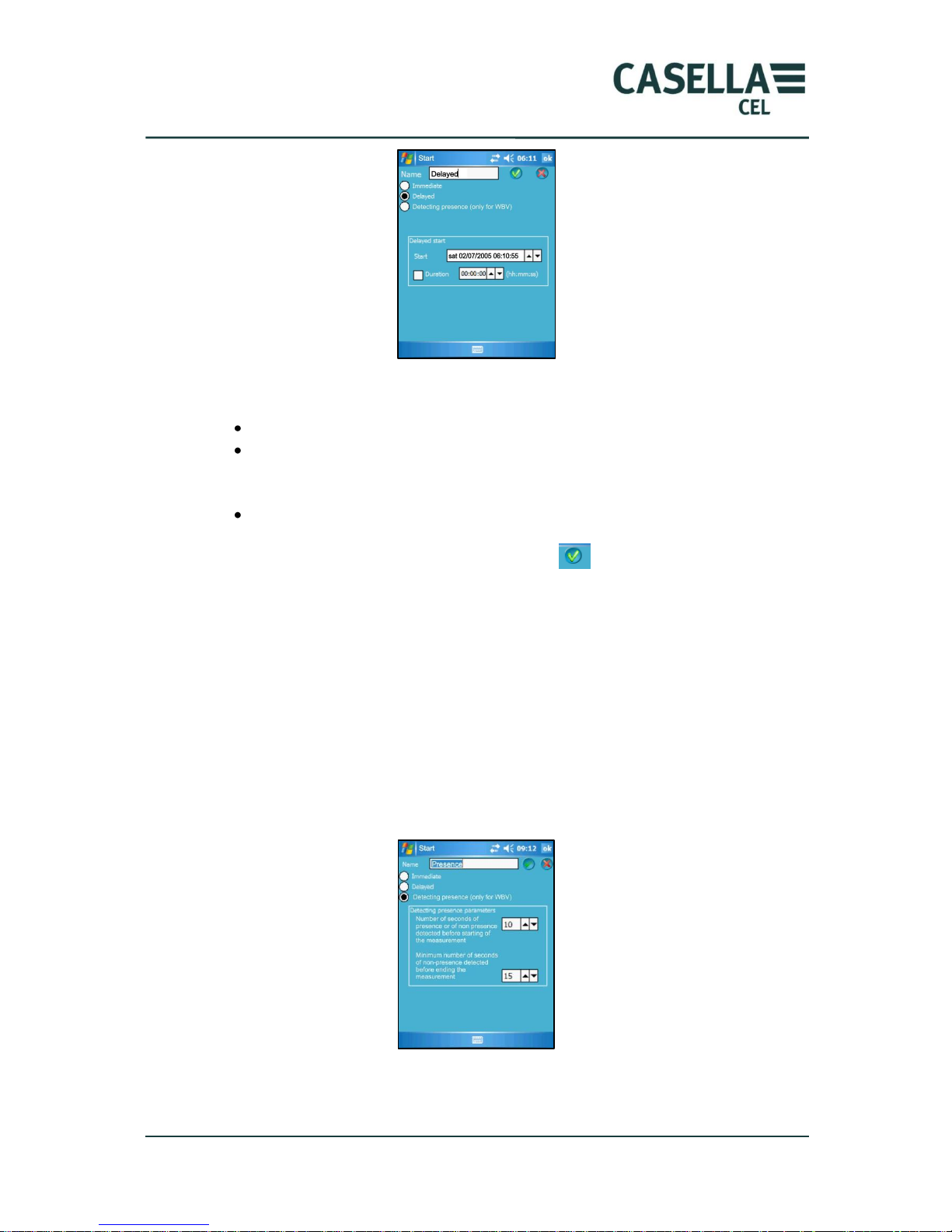
4.5.2.2 Delayed start
The operator can prepare the instrument ahead of time. Thus, he/she can program a
measurement date and time for, e.g., the next day. Once the programming is
validated, the instrument goes in stand-by mode until the programmed date and
time.
Like for immediate start, the operator can select to stop the measurement after a
defined time.
Keyboard icon
Page 23
CEL-960 Human Vibration Meter
23 Casella CEL
To program this start mode, the operator must enter:
The configuration name.
The measurement starting date and time, by successively selecting the
different fields for the date and time, using either the arrows, or the
keyboard.
The measurement duration, using the same input procedure.
The configuration is validated by clicking on icon .
After 5 min, the Instrument goes in stand-by mode by automatically switching to
the Off position. It can be restarted by pressing the On/Off key.
There is minimal consumption during the stand-by phase.
4.5.2.3 Start on detection of presence
This programming mode is only available in whole-body (WBV) measurement mode
and provided a WBA001 transducer is available, since it is the only transducer with
a built-in presence detector. The user can program the minimum presence time of
the operator on the seat, which will determine the start of the measurement. The
non-presence duration will determine the time of non-presence of the operator on
the seat, which will be taken into account to stop the measurement.
The calculation time will be displayed in the real-time results screen in addition to
the measurement time.
Page 24
CEL-960 Human Vibration Meter
24 Casella CEL
4.5.3 System configuration screen
4.5.3.1 System parameters
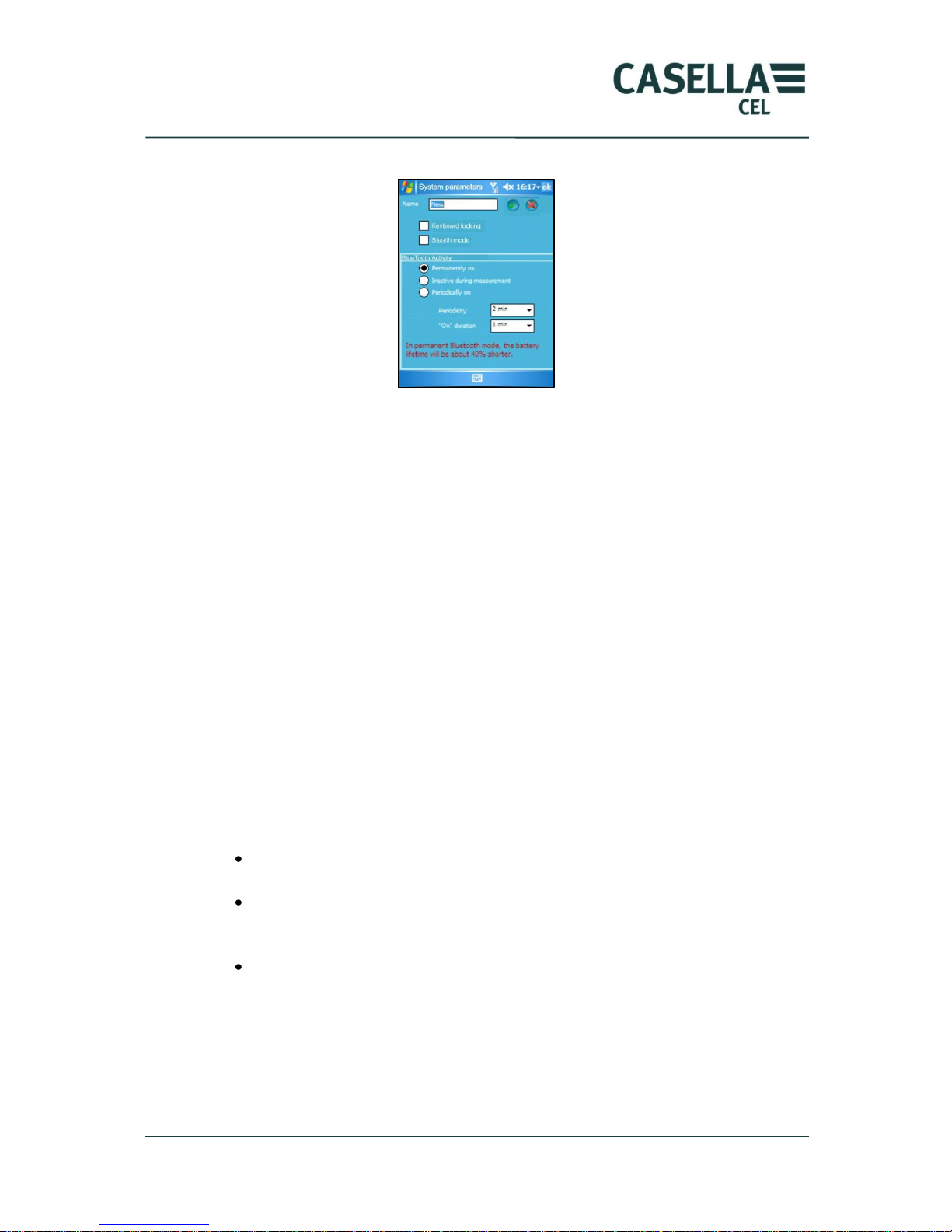
Locking the keyboard is a simple and efficient way of preventing the individual
wearing the CEL-960 of stopping the measurement. The user can invalidate this
action by checking the corresponding box “Use of the keyboard”.
In order to increase the operating life of the instrument and/or to make it as
discreet as possible for the person wearing it, one can disable the LEDs by checking
the “discreet mode” box.
The LED that indicates by blinking that CEL-960 is in measurement mode is
disabled. There is thus no difference between a CEL-960 instrument that is running
and one that is shut down. One just needs to press any key to reactivate the
measured indicator for a few seconds.
The alarm LED is not dealt with by the discreet mode. The user must disable it in
the Alarm configuration screen by checking the “Never” box.
4.5.3.2 Bluetooth wireless communication
For energy saving reasons, the activity of the Bluetooth communication can be
managed in several ways:
The connection is always active. In this case, the PC can act on the
instrument and display vibration indicators.
The connection is “deactivated during measurement”: the PC can no longer
access CEL-960. One must press a button on the CEL-960 keypad to
reactivate the connection.
The activity can be made periodic: it is reactivated during a programmed
time and at regular intervals.
When the activity of the wireless connection is periodic, it can be difficult to gain
control over CEL-960 again depending on the programming of frequency and
duration parameters.
Page 25
CEL-960 Human Vibration Meter
25 Casella CEL
When lit, the Bluetooth LED shows the availability of the connection. Its blinking
indicates an activity on the connection.
However, even if the keyboard is locked and the wireless communication is
disabled, pressing on the keyboard allows (during 5 minutes) reactivation of the
Bluetooth connection. It is thus possible to access measurements performed by the
Instrument and to check, e.g., the battery status. The user can also “arbitrarily” stop
the measurement using the PC.
4.6 Measurement mode
Once the operator has completed the configuration of the CEL-960 instrument,
he/she must send it to all the instruments in the „workshop‟. On the main
configuration screen, icon “Send configuration” is selected.
Each instrument present in the „workshop‟, i.e., listed on the right side of the screen,
receives this configuration and, in turn, sends to the PC the programmed date and
time to end the measurement.
With this information, the operator can activate the measurement, correct the
configuration or recharge the CEL-960 battery, if the expected measurement
duration is not suitable.
The end date and time predicted by the CEL-960 takes into account the battery
capacity and the memory capacity.
Once the ending date and time are validated for a CEL-960, a “configuration
activation” icon is displayed. The operator can validate this information for each
CEL-960.
By clicking on icon , one or several CEL-960 present in the „workshop‟ are
activated, depending on the status of this field : .
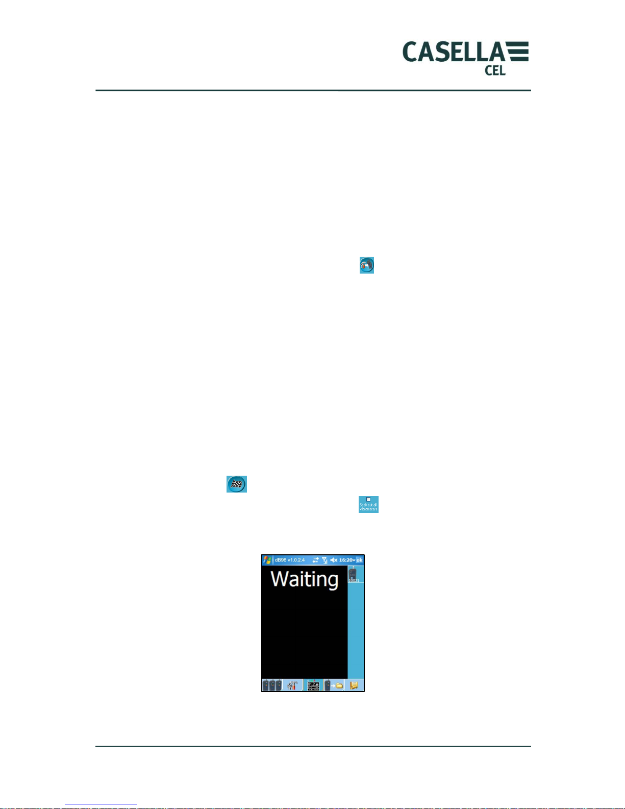
The following screen is displayed during the system initialisation phase (~20s):
As soon as the measurement starts on CEL-960 (immediate start), the green LED
(on the CEL-960) blinks once per second to indicate the measurement is underway.
Page 26
CEL-960 Human Vibration Meter
26 Casella CEL
It turns off after 1 minute if the “discreet” mode has been selected in the system
configuration.
In case of a delayed start, the green LED turns off after a few minutes, the
instrument goes into “Standby” mode until it is reactivated by the real-time internal
clock. The Measurement (On/Off) LED is reactivated once the CEL-960 reaches the
specified time.
4.6.1 Measurement screen
During the measurement and provided the configuration of the wireless connection
allows for it, the user can:
View results in real-time on the PC display.
Code (mark) specific events.
Record written comments.
Record the vibration signal (.wav file).
To do so, the operator must activate the “measurement” tab: .
4.6.1.1 Visual display of measurement results
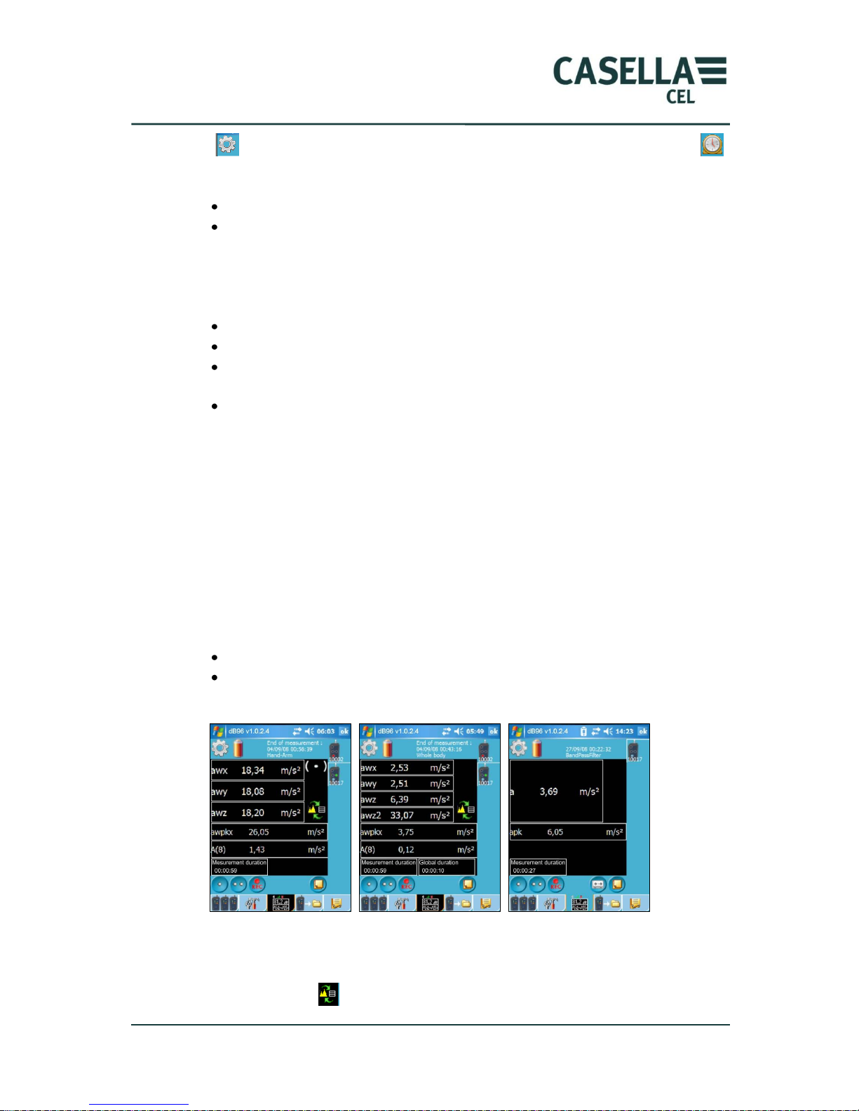
The results screen displays the results, as well as the status of the selected CEL-960.
To select a CEL-960 instrument, click on its icon on the right side of the screen. A
frame surrounds the active CEL-960 instrument.
The Measurement screen consists of several sub-screens:
The upper part or status area.
The centre part or results area.
The lower part or command area.
The bottom of the screen is always used to navigate through main screens.
The right part of the screen displays the CEL-960 instruments present in the
„workshop‟.
Depending on the configuration, displayed results will be different. In any event, the
operating principle remains the same: clicking in one of the areas displays the
relevant results.
4.6.1.1.1 The status area
This area displays information relative to the instrument selected in the right side of
the screen:
Measurement/stand-by status:
Page 27
CEL-960 Human Vibration Meter
27 Casella CEL
The animated icon represents a CEL-960 in measurement mode, while icon
represents an instrument waiting to start. Also shown is:
Status of the CEL-960 battery.
Expected measurement ending date for the selected CEL-960.
4.6.1.1.2 The results area
The results area consists of 4 areas:
Area “acceleration and coding, overload and under-load indicators”.
Area “peak level”.
Area “global levels”, (A(8), VDV) corresponding to the displayed
measurement duration.
Area “duration”.
The operator can read the band-pass (unweighted) or weighted acceleration by
simply clicking on this area.
In the “peak level” part, the operator can view the weighted or un-weighted peak
level.
In the “global results” area, he/she can access results to the measurement duration:
A(8).
In case of a whole-body measurement with the WBA001 transducer integrating a
presence detector, 2 durations are displayed:
The total duration of the measurement calculated from the beginning.
The calculation duration corresponding to the total measurement duration
minus durations when the operator was not seated.
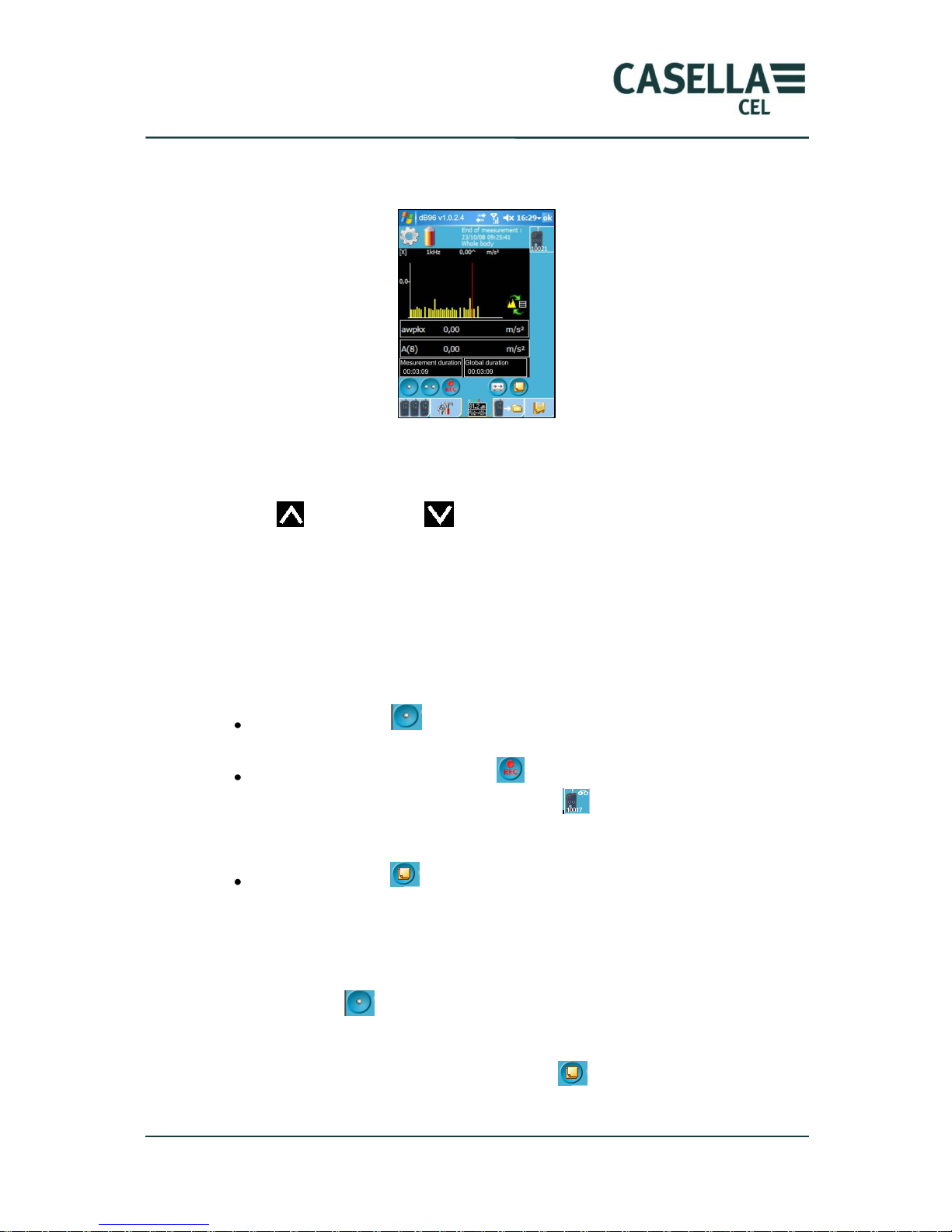
If the user selects to record an octave or a 1/3 octave spectrum by clicking on the
„change screen‟ icon , he/she switches from the above display to the display of
Hand-arm mode
Free mode
Whole-body mode
Page 28
CEL-960 Human Vibration Meter
28 Casella CEL
the spectrum of the selected channel (the spectrum is possible on one of the
channels only).
After the measurement is started „waiting‟ is displayed on the PC screen until the
CEL-960 measurement has stabilised. The recording of data and the real-time
display start as soon as the sign appears on the selected CEL-960.
Overload and under-load levels are automatically shown based on the
transducers and calibration.
4.6.1.1.3 The command area
This area includes icons for adding information to the measurement file. The CEL960 records weighted or un-weighted acceleration samples at every integration time
(averaging interval). To mark the occurrence of a specific vibration phenomenon in
the measurement file, the operator can use one of the following icons:
Coding (Marking) : the indicator corresponding to code (marker) 1 or 2
will be displayed on screen to indicate the coding of stored data.
Recording of the vibration signal : a recording icon blinks in the top right
corner of the icon of the selected CEL-960 . The vibration signal is
recorded at the frequency selected in the Audio configuration. The icon
disappears when the recording stops.
Written comment : a window opens up to enter a comment regarding the
measurement.
These various tools can also be combined.
At the beginning of the particular vibration phenomenon, the user must click on one
of the coding icons , which leads to the marking of all data recorded from that
moment on. They are assigned to the selected code.
At the end, the user can enter a written comment , specifying that this coding
corresponds to such specific vibration event.
Page 29
CEL-960 Human Vibration Meter
29 Casella CEL
The user can also perform the real-time recording of the vibration signal by clicking
on icon for further laboratory analysis.
In this way, all elements required to interpret results will be available.
The recording of the vibration signal (.wav file recording) and the calculation of the
spectrum are ALWAYS achieved on the SAME CHANNEL.
4.7 Measurement stop
Depending on the configuration, the measurement will be stopped automatically or
manually.
Even if the end date and time have been programmed, the user can still manually
stop the instrument.
There are different ways of stopping the CEL-960:
Through the instrument keyboard. This stop is allowed provided the
keyboard has not been disabled. The operator can stop the measurement by
holding the on/off fey for more than 10 s.
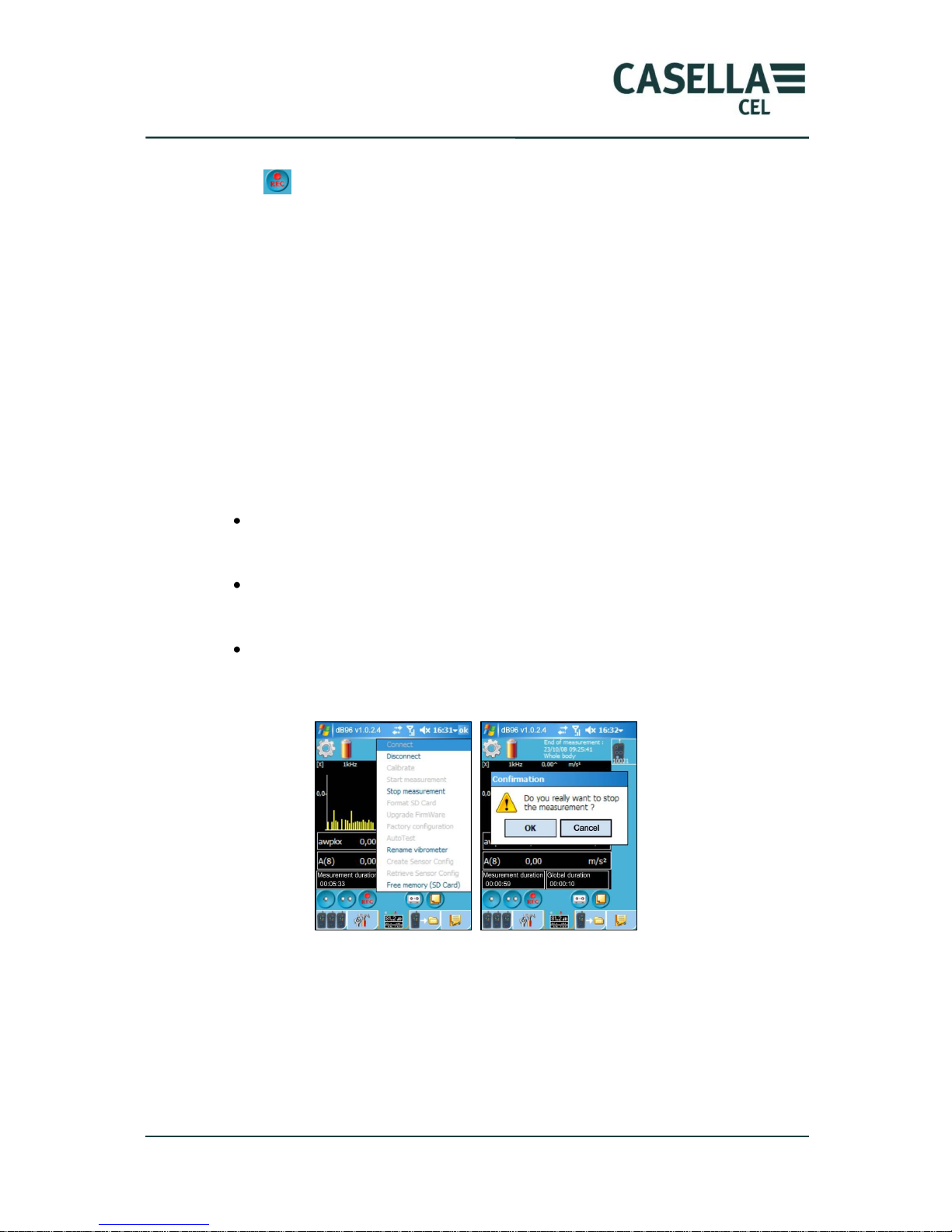
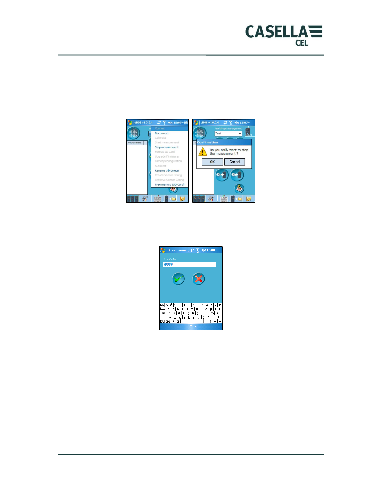
Through a command from the PC. a right click on the instrument icon to
stop will give access commands (shown below). Clicking on “Stop
measurement” will stop the measurement.
Measurements will be stopped automatically if the battery level is low. In
this case, the measurement file is closed before the instrument is shut down
and a message is sent to the PC.
Once the measurement is stopped, the Measurement (On/Off) LED remains on
(green), then after 5 min, the LED blinks for a few seconds and the CEL-960 shuts
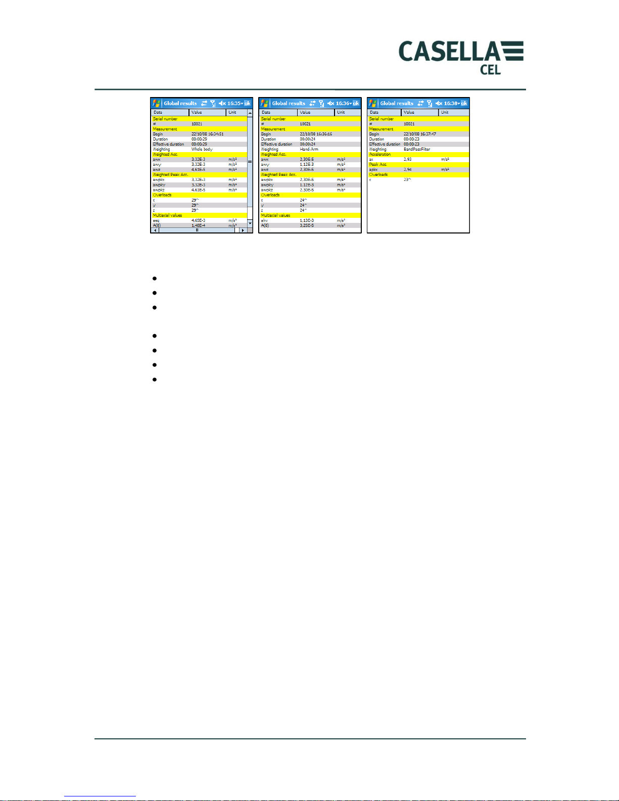
down. On the PC, the screen below is displayed, listing all global results
programmed in the configuration.
Page 30
CEL-960 Human Vibration Meter
30 Casella CEL
Depending on the configuration, the following information may be displayed:
The instrument number.
The date, time and duration of the measurement.
The results relative to the weighted or un-weighted acceleration on the 3
axes.
The minimum peak values along the 3 axes.
The weighted or un-weighted peak factors.
The multi-axis resuts: av, ahv, A(8), VDV….etc
Coding (markers), overload, counters etc
Counters represent the number of overloads specific to each transducer.
A counter exists for the presence detector integrated into the whole-body
transducer.
The “alarm” counter represents the number of alarm triggers. For this counter, a
specific case exists if the alarm refers to A(8) or VDV: obviously if the alarm level
has been exceeded once, this situation remains until the end of the measurement.
The number of results displayed is directly related to the operator‟s selections in the
measurement configuration screen.
4.8 Transfer / Deletion of files
Filenames are generated as follows:
“#CEL-960 MonthDayYear_HourMinuteSecond.BIV”.
For instance, the name “010017_080908_0405_120706000.BIV” indicates that
this file was created on 0809085, i.e., on September 8, 2008 at 120706, i.e.,
12:07:06.
4.8.1 Transfer via Bluetooth
When the measurement is stopped, the user can transfer the list of files stored in the
different CEL-960 instruments, then retrieve signal (.wav) files and store them in a
folder on the PC.
Page 31
CEL-960 Human Vibration Meter
31 Casella CEL
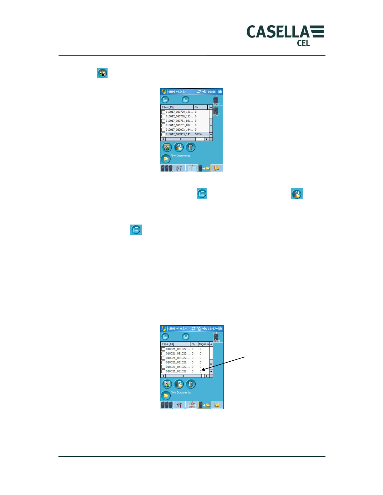
To do so, he/she must select the corresponding CEL-960 instrument and click on
icon . The files in the CEL-960 will be shown, as per the example below.
All measurements can be transferred to the folder indicated at the bottom of the
screen “\My Document”, by clicking on (select all), and then on icon
(transfer files).
If the operator wants to transfer only one file, he/she should uncheck all files by
clicking on icon and then check the box corresponding to the selected file.
Data is archived in a sub-folder of the folder mentioned at the bottom of the screen.
The name of the measurement sub-folders are built based CEL-960 serial
number(s) and the date and the time of the measurement start.
Example: 010017_080916_165459000 is the sub-folder of a measurement
performed on September 16, 2008 at 16h54m59s.
If the data file is associated with signal (.wav) files (if they were stored), this
information is contained in the „signals‟ column at the right of the screen.
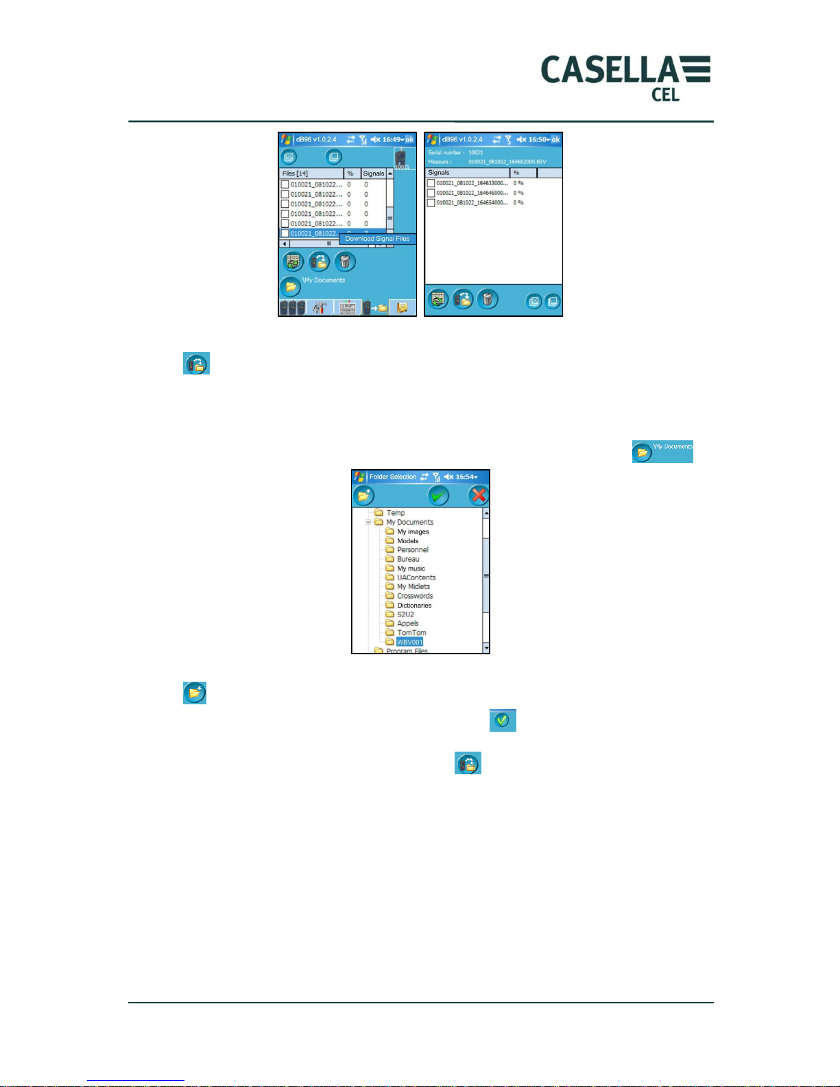
Right clicking (or pressing the stylus for a longer time) on the data file will open the
list of „signal‟ files to transfer.
3 „signal‟ files associated
to the *.BIV file
Page 32
CEL-960 Human Vibration Meter
32 Casella CEL
Check part or all of the signal files associated with the *.BIV file and click on icon
to transfer them to the folder containing the *.BIV file.
Due to their potentially large size, it is recommended that signal files are transferred
to a PC using the USB connection.
The operator can create or change the storage folder by clicking on icon .
By default, data are stored in My Documents\. To create a new folder, click on icon
. This leads to the opening of a new window used to enter the name of the folder.
Once the folder is named, validate by clicking on .
Once the storage folder is selected, click on to transfer and store data in this
folder.
The progress of the transfer is indicated at the right of the filename by the
percentage of stored data.
We recommend not interrupting a transfer in progress.
Vibration signal recording files (*.WAV) are not transferred at the same time as
time data files as this would increase transfer time. They should preferably be
transferred through the USB connection.
Page 33
CEL-960 Human Vibration Meter
33 Casella CEL
4.8.2 Transfer via USB on PC
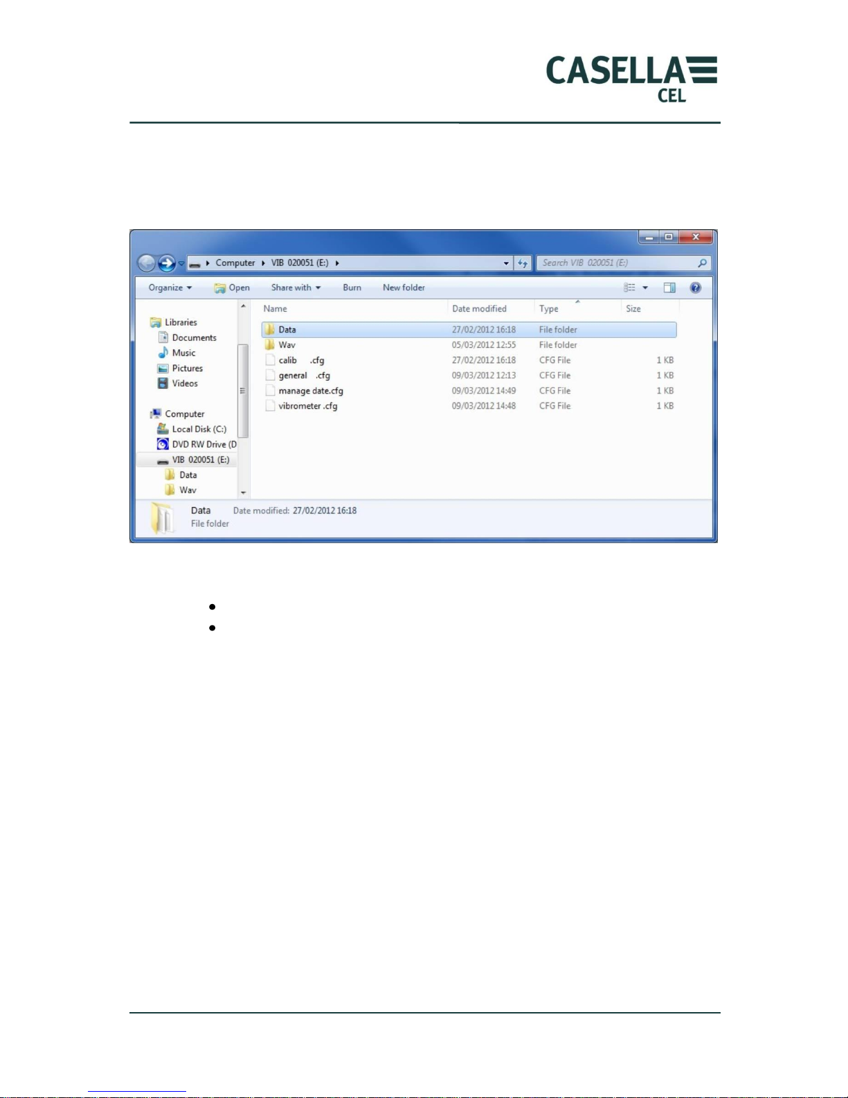
For a quick transfer of large files the USB connection should be used. When CEL960 is connected to the PC via the USB cable, the CEL-960 memory will be
displayed in the file explorer as a mass storage system (See section 5.4.2).
The SD card contains configuration files and data files:
The „Data‟ folder contains data files : *.BIV
The „Wav‟ folder contains real-time signal recording files.
If configuration files were to be deleted, the operator would lose part of his/her
configurations, such as calibration, but basic instrument information would not be
lost. When these files are deleted upon power up, the LED on the front panel lights
up in red and error system 0x80 is displayed on the PC. Shut down and restart the
CEL-960 to create the basic files.
4.8.3 Deletion
Once data is transferred and stored on the PC, the operator can delete the CEL-960
internal memory. This deletion can be achieved globally or by selecting individual
files to delete.
Page 34
CEL-960 Human Vibration Meter
34 Casella CEL
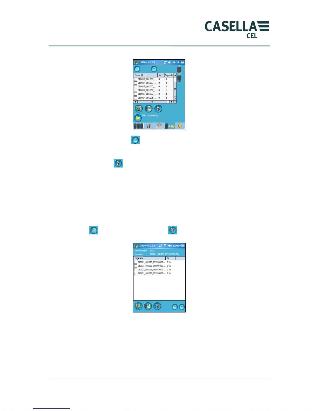
4.8.3.1 Deletion of *.BIV data files
Check the “Select all” box to delete all files, or only the boxes of the files to
delete.
Then click on icon to delete the files from the CEL-960 memory.
Deleting *.BIV files will also delete associated files (*.wav).
4.8.3.2 Deletion of *.WAV signal files
When the CEL-960 includes the „signal‟ recording (.wav file) option, *.WAV files can
be associated with *.BIV data files. These files will be automatically deleted when
the *.BIV file with which they are associated is deleted. However only 500 *.WAV
files can be deleted, directly in the screen below by selecting the files separately or
globally , and then by clicking on icon .
4.9 Reading data stored on the PC
By selecting this tab, the user can consult global results and associated secondary
text files (*.txt) or sound files (*.wav).
Secondary files (*.txt and *.wav) associated to the main file may not always be
present depending on the configuration of the CEL-960.
Page 35
CEL-960 Human Vibration Meter
35 Casella CEL
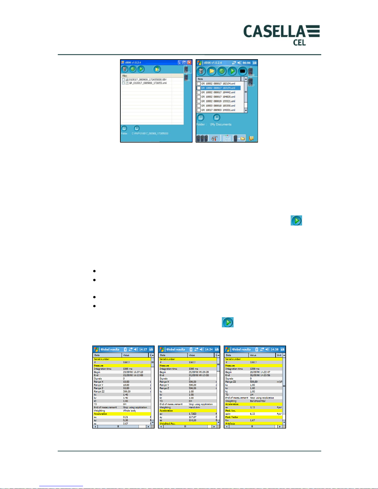
These screens allow stored data to be viewed. The first screen displays the list of all
measurement folders (after each measurement, a specific folder is created in the
root folder). On this screen, the result file “GR_010003_081007_1827724.xml”,
which is displayed below the list of measurement folders, is a global results file
(*.BIV), the time data of which has not been transferred to the PC. It will disappear
as soon as the transfer is finished and the folder created to store data is opened for
the first time.
To open a measurement storage folder, select this folder and click on icon . The
list of the files associated with this measurement is displayed in the 2nd screen
shown above.
This folder contains:
The *.BIV file containing time data that will be processed by dB98
The global results file (tagged with RG….xml: results over the total
measurement period)
“Text” comment files (tagged with Note ….txt)
*.WAV files containing the recording of the vibration signal
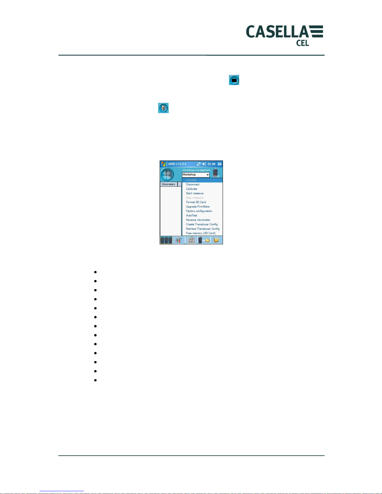
By selecting the global results file and clicking on , the operator can access one
of the 3 screens according to the selected measurement mode.
Example of global results screen (Whole Body, Hand Arm, Free)
Page 36
CEL-960 Human Vibration Meter
36 Casella CEL
The operator can also view text comments by selecting files of the “NOTE….txt”.
While reading a signal file (*.wav), clicking on icon will interrupt the process.
Folders and measurement files can be deleted from the PC memory by selecting
them and clicking on icon . The operator will be prompted for confirmation.
4.10 Secondary functions
These functions are specific to the selected CEL-960 instrument. They are available
by right clicking the CEL-960 icon.
Here are some of these functions:
Connect to the CEL-960
Disconnect from the CEL-960.
Calibrate the CEL-960.
Manual start of the measurement.
Stop the measurement.
SD Card formatting.
Update the CEL-960 internal firmware.
View the factory configuration.
Auto-test the CEL-960.
Change the name of the CEL-960.
Create a new transducer configuration.
View current transducer configuration.
View available memory.
4.10.1 Connection
When the CEL-960 instrument is on but is not connected by Bluetooth to dB96, the
operator can force a connection by clicking on „Connect‟.
4.10.2 Disconnection
If it is necessary to disconnect a CEL-960 with the connected PC, select „disconnect‟.
Page 37
CEL-960 Human Vibration Meter
37 Casella CEL
4.10.3 Calibration of CEL-960
Launching the procedure will delete the previous calibration.
Whatever the calibration type, the relevant transducer must be connected.
This function can be used to start calibrating CEL-960 from the PC. In addition to
classic calibration, this calibration includes offset calibration. Depending on the
type of transducer to calibrate (mono-axial or tri-axial), the number of channels will
be 1 or 3.
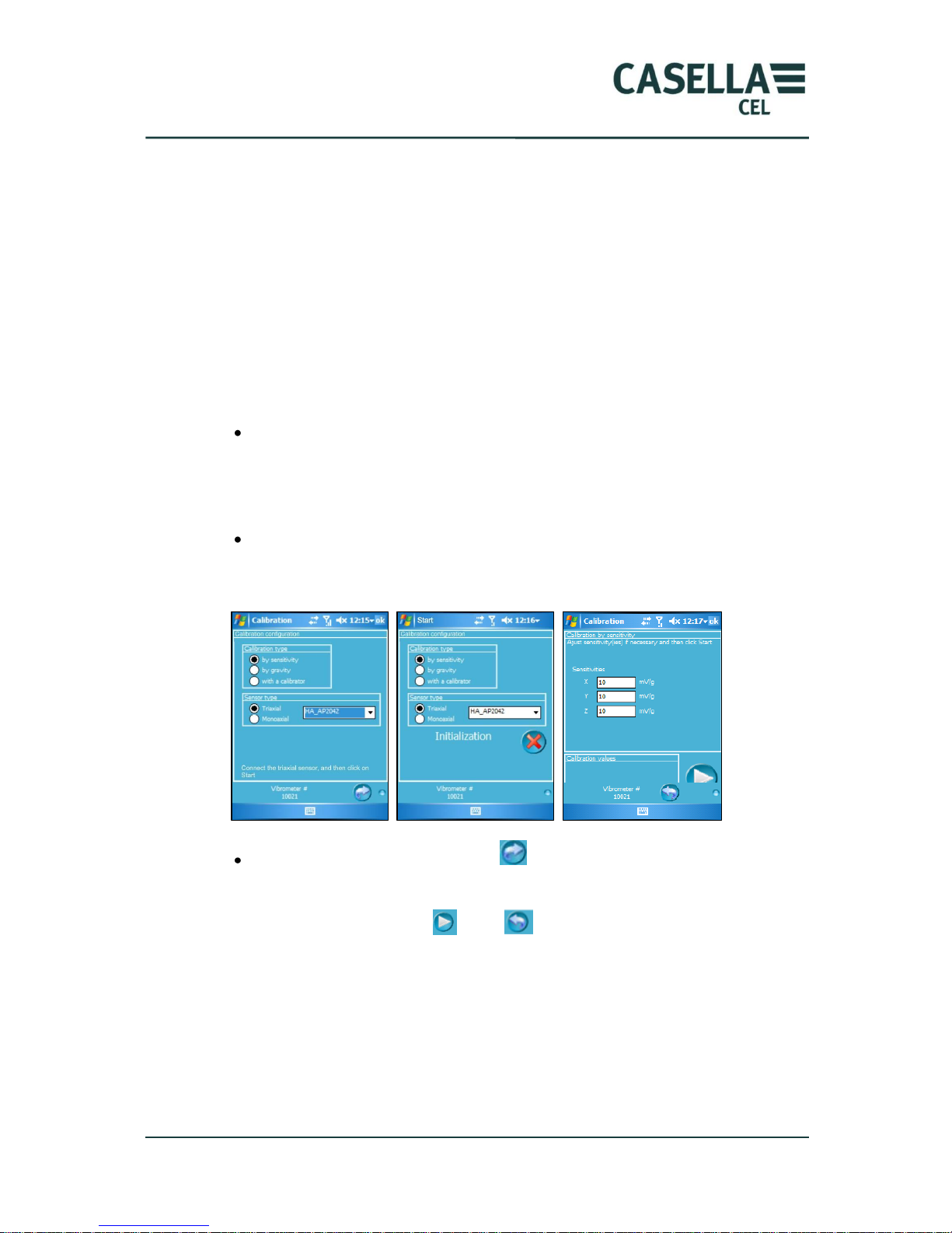
The procedure to follow is summarised in the screens below. Indications help the
operator during the calibration process. After right clicking on the selected CEL-960
in the pull-down list:
Click on calibration to display the following screen. The operator selects the
type of calibration to perform:
o Calibration by sensitivity.
o Calibration by gravity: possible only with the WBA001 transducer.
o Calibration by dynamic vibration calibrator.
And the type of transducer to calibrate:
o Tri-axial.
o Mono-axial.
Start the operation by clicking on .
The operator selects the transducer reference on the following screen and starts the
offset calibration by clicking on . Icon can be used to go back to the
previous step.
4.10.3.1 Calibration using sensitivity
This is the simplest and fastest type of calibration. To perform this type of
calibration, enter the theoretical sensitivity of the transducer and validate (e.g.,
enter 9,5 mV/g and not 9.5 mV/g).
Page 38
CEL-960 Human Vibration Meter
38 Casella CEL
4.10.3.2 Calibration using a dynamic calibrator
The transducer will need to be screwed onto the calibrator in accordance with the
operating procedure of the calibrator. For the calibration of whole body transducers,
the transducers must be removed from the seat pad.
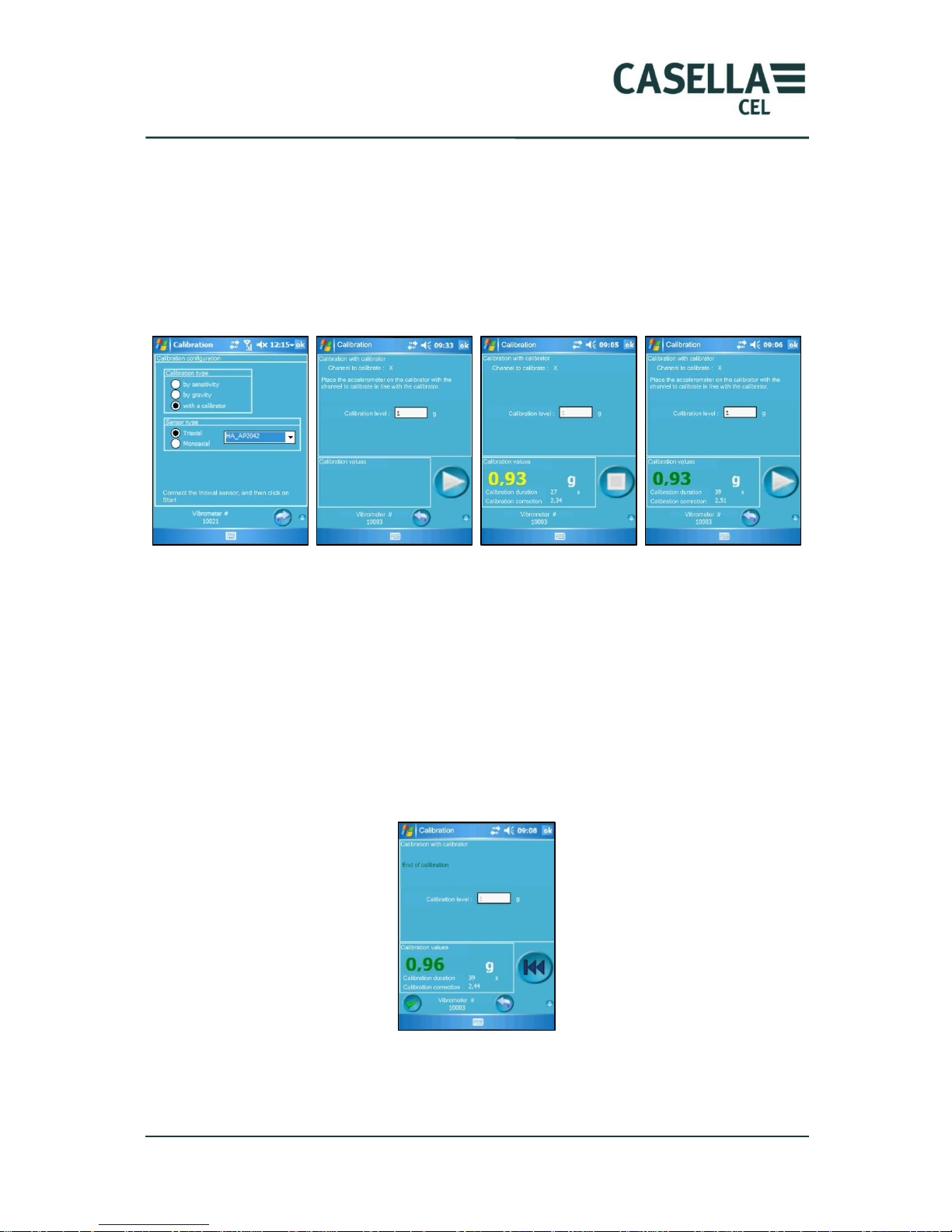
These screens show the progress of the calibration process using a calibrator.
Screen 1: Generic screen to start calibration
Screen 2: Start screen for the calibration of channel X
Screen 3: Calibration of channel X in progress
Screen 4: End of calibration for channel X, start screen for the calibration of channel
Y
After a set-up phase, the calibration procedure starts by the calibration of channel
X, then channel Y, and finally channel Z (in the case of a tri-axial transducer). The
operator shall carefully follow the information displayed on the screen.
Screen 1
Screen 2
Screen 3
Screen 4
Page 39
CEL-960 Human Vibration Meter
39 Casella CEL
When the 3 channels are calibrated, the operator can either validate , go back to
the previous step with icon , or to the beginning of the calibration procedure by
clicking on .
4.10.3.3 Calibration using gravity
This type of calibration requires no additional instrumentation, but the system must
be able to measure the continuous component of the vibration. This can be achieved
only with a WBA001 (whole body) transducer. The operator shall scrupulously
follow the instructions displayed on the screen. The calibration shall proceed until
the message „End of calibration‟ is displayed. Hold the accelerometer (within seat
pad) stationary with the relevant axis in a vertical position.
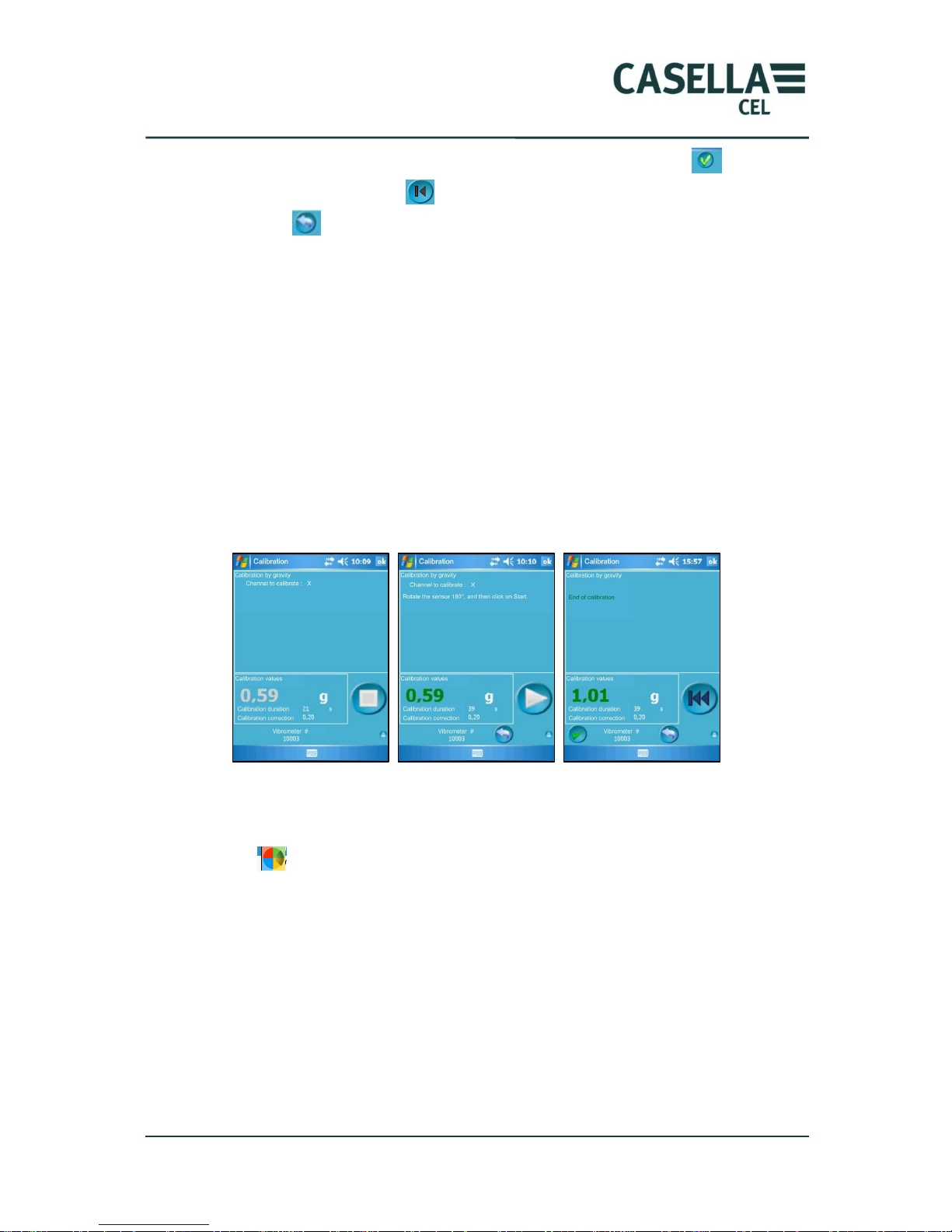
The orange colour represents the fact that a stable value has been reached, while the
green colour means that the final value has been found.
The following screens present the calibration procedure. Actions to be performed on
the transducer are indicated at the top of the screen.
After each validation, the value stored previously is overwritten. One must then
complete the calibration procedure to the end.
Validation of channel Z will end the calibration procedure.
If icon is displayed in a screen, this means that the PC is attempting to
connect to CEL-960. Check that the Bluetooth communication LED is on and is
blinking. Otherwise, turn CEL-960 on, quit the window, then the software and
restart the operation.
4.10.4 Measurement start
This function can be used for an immediate start of the measurement without prior
sending of the configuration to the CEL-960. The instrument will start the
measurement using the previously stored configuration.
Page 40
CEL-960 Human Vibration Meter
40 Casella CEL
This procedure is not recommended if the instrument has several operating modes
(e.g., whole-body and hand-arm modes). With this procedure, no indication is
provided on the ending date and time of the measurement.
4.10.5 Measurement stop
The measurement can be forced to stop using this command.
4.10.6 Rename the instrument
The operator can associate the name of the individual wearing the CEL-960 or any
other identification information with the instrument number.
4.10.7 Factory configuration
With this function, the operator can know the intrinsic characteristics of the CEL-
960. Some of the information listed on this screen will be specifically useful if a fault
occurs with the instrument.
Page 41
CEL-960 Human Vibration Meter
41 Casella CEL
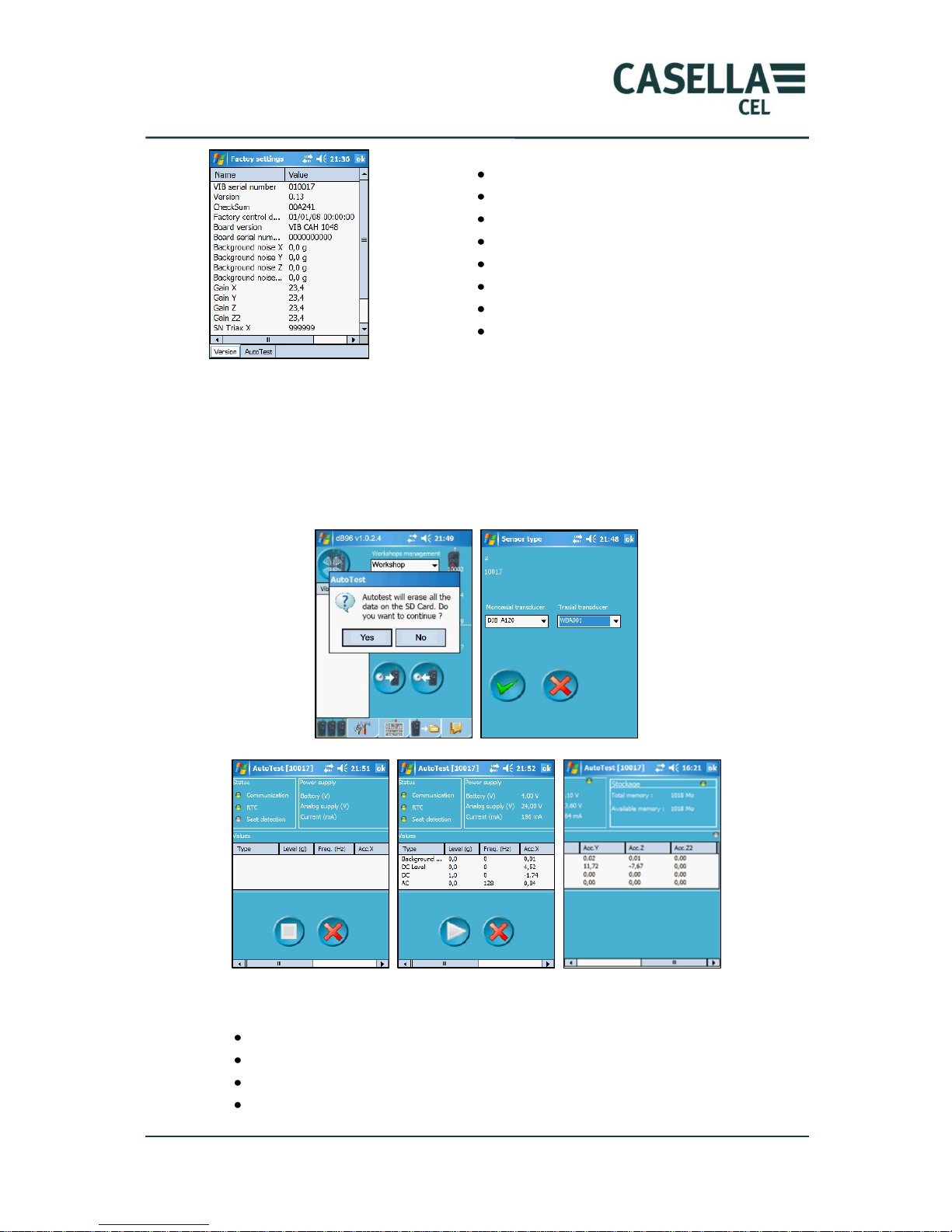
4.10.8 Auto Test
This function is used to assess the metrological validity of the instrument.
To do this auto test, the transducer must be present on the instrument.
Caution: the auto test destroys all data present in the CEL-960 memory. Do a
backup before starting this action.
The following tests are performed:
Bluetooth communication.
Real-time clock: operating check-up through a read/write operation.
Presence detector (WBA001 option).
Measurement of the internal battery voltage.
CEL-960 serial number
Firmware version
Firmware checksum
Date of the latest auto test
Version of the electronic card
Background noise characteristics
Electronic gain for each channel
Serial numbers of the transducers
Page 42
CEL-960 Human Vibration Meter
42 Casella CEL
Measurement of the voltage of the analogue part.
Measurement of consumed current.
The test results are displayed in green if the test is OK and in red if tolerances are
exceeded.
Background noise level in the 0.4Hz-4kHz band.
DC level: continuous level.
Continuous level in auto test for 1g.
AC level for a signal in auto test at 128Hz.
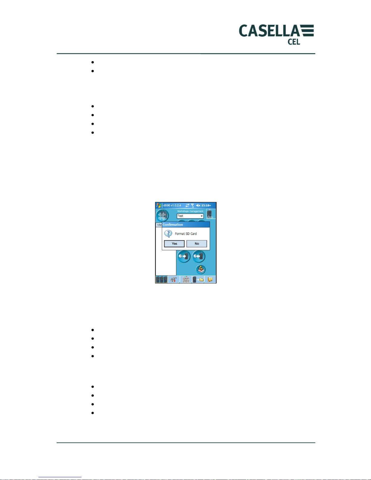
4.10.9 SDCard memory formatting
Deleting files will erase the data on the SDCard. A damaged file can inhibit reading
or storage operations. In this case, the memory must be re-formatted to ensure
proper operations.
Launching function “SDCard formatting” will start this action.
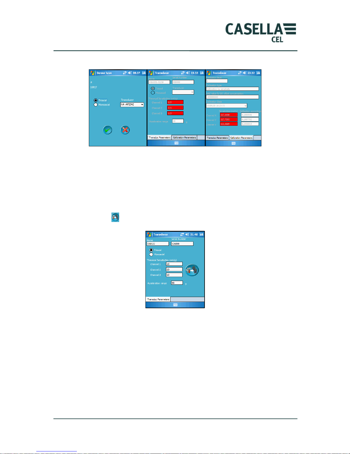
4.10.10 Reading of transducer characteristics
This function is used to know the type of transducers available and their physical
characteristics (screen 1):
Mono-axial, triaxial.
Reference, serial number.
Theoretical sensitivity of each channel.
Maximum measurement range.
As well as calibration results (screen 2):
Level and type of the latest calibration.
Offset level.
Date and time of calibration.
Real sensitivity and calibration correction for each channel.
Page 43
CEL-960 Human Vibration Meter
43 Casella CEL
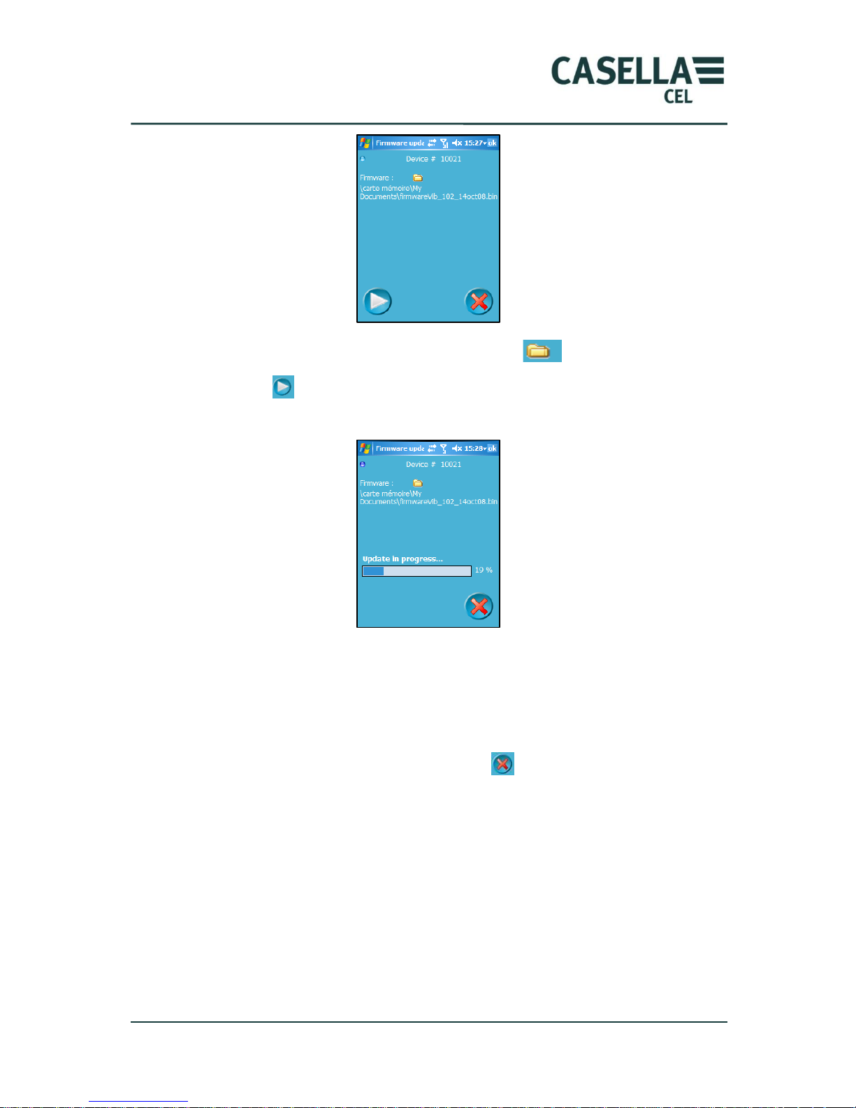
4.10.11 Creating a transducer
The operator can define the characteristics of a transducer if designed to operate
with a CEL-960.
In this case, the information relative to this transducer must be entered in the
screen below. Overload and under-load levels will be adjusted accordingly by CEL-
960.
Click on icon to transfer the information to the instrument.
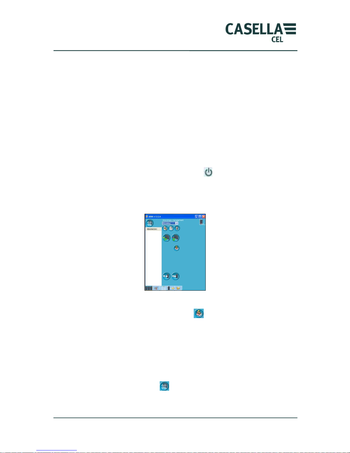
4.10.12 Updating the firmware
The internal firmware can be changed via an upgrade by activating the “Firmware
update” function. The operator must copy the update file in the reference folder on
the PC and then start the updating procedure.
Screen 1
Screen 2
Page 44
CEL-960 Human Vibration Meter
44 Casella CEL
Select file firmware file to upload by clicking on icon , then select the file.
Click on icon to start uploading the new program file to the CEL-960. Make sure
there is adequate battery life in the CEL-960 prior to the upload process.
The uploading procedure last about 3 to 4 minutes, switch the instrument off and
make sure that the software version number corresponds to the uploaded version by
checking the internal configuration (see section 4.10.2).
If an error occurs during the process, restart the operation.
Quit the screen by clicking on the “Cancel” icon .
Contact the Customer Service Department before doing this operation, should you
find the provided instructions not clear enough.
We recommend doing this operation with the PDA at close range to the CEL-960
(50 cm maximum).
Page 45
CEL-960 Human Vibration Meter
45 Casella CEL
5 Using the CEL-960 with a PC
The PC application is very similar to the PDA application described in Section 4. All
functions are the same for the two applications. The only differences deal with the
implementation of the application on the PC and the user interaction is through the
keyboard.
5.1 Bluetooth communication
The operator must check that the Bluetooth peripheral device installed on the PC is
of the Radios Bluetooth type (Windows default peripheral). If this is not the case,
the existing peripheral device must be uninstalled – making sure it is not used
elsewhere. The Windows peripheral should then be installed.
If Bluetooth is not integrated in the PC, an external Bluetooth dongle can be
connected, which will be automatically detected by the computer.
Turn CEL-960 on by pressing on the On/Off key .
5.2 Launching software dB96 on the PC
After launching the application, the user of dB96 version PC is displayed: it is
exactly the same as the interface of PDA version PC. Functionality is also the same.
The operator must first enter the licence number corresponding to the options
available on the CEL-960 by clicking on icon , which adds the purchased options
to the software user interface.
In screens where text input is possible, the operator can use the PC keyboard (there
is no virtual keyboard icon).
No oral comment can be recorded in the PC version.
5.3 Implementation
As seen previously, instruments present in the wireless communication range are
searched for by clicking on icon .
Once again, this range is about 10m in the case of a PC equipped with class-2
Bluetooth. It can be longer for class-1 Bluetooth.
Page 46
CEL-960 Human Vibration Meter
46 Casella CEL
Please refer to the previous chapter “Using CEL-960 with a PDA” for a description
of all functions.
5.4 Data transfer
To process data recorded on the CEL-960 instrument using a spreadsheet or dB98
software, the operator must first transfer them from the CEL-960 to the PC.
Different types of data can be stored on CEL-960:
*.BIV files containing time data recorded over the specified integration time
(IT)
*.txt files: written comment files
*.WAV files: oral comment files
*.WAV files containing the recording of the vibration signal (option with
„expert‟ pack)
5.4.1 Data transfer via Bluetooth
This transfer is achieved in the same way as with a PDA (see section 4.8.1).
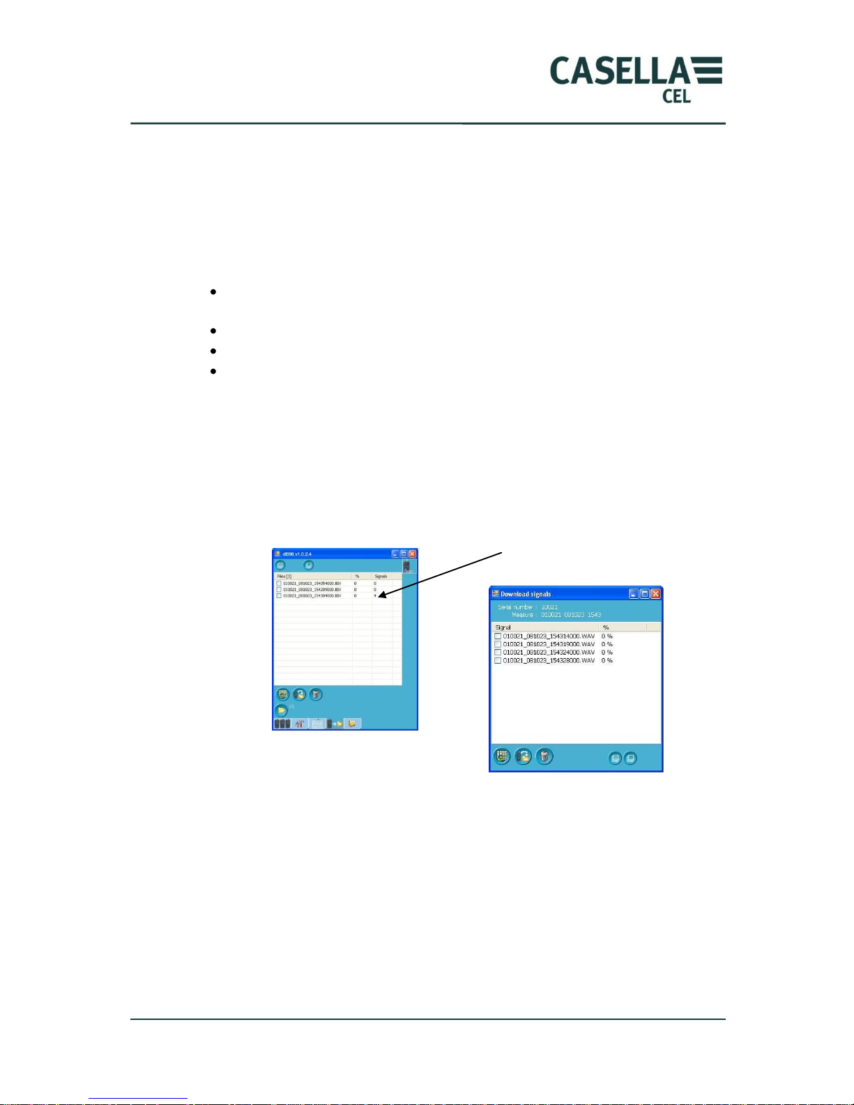
Given the larger size of a PC screen (as compared with the PDA screen size), one can
directly see the number of vibration signal files recorded during the period stored in
the *.BIV file.
Right clicking on the *.BIV file will display all *.WAV files recorded simultaneously
with time data and that can be transferred to the PC hard disk using the Bluetooth
connection. This type of transfer is not recommended if “signal” files have a large
size.
5.4.2 Data transfer via USB
This is the fastest and most appropriate method to retrieve data from the CEL-960
for further processing by dB98, especially if “signal” files have been recorded during
the measurement.
4 files associated to
the *.BIV file
Page 47
CEL-960 Human Vibration Meter
47 Casella CEL
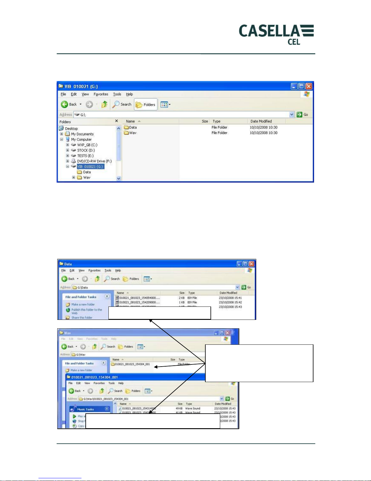
In this case, the CEL-960 must be connected to the PC using the USB cable. The
CEL-960‟s storage memory will be displayed in the Explorer as an additional disk.
The “Data” folder contains all *.BIV time data files, while the WAV folder contains
all folders for the “signal” files associated with the different *.BIV files.
The maximum number of *.WAV files is 100 files per WAV sub-folder. There can
then be several WAV folders associated with the same *.BIV file.
By importing *.BIV files in dB98 processing software, all files associated with these
files (*.wav, *.txt and *.wav comment files) are also imported. Please refer to the
dB98 documentation for more details.
DATA Directory : Files *.BIV
WAV Directory\ Sub Directory \ files *.WAV
*.BIV file and its associated WAV
directory that contains 2 « signal »
files on the measurement period
Page 48
CEL-960 Human Vibration Meter
48 Casella CEL
6 dB96 System errors
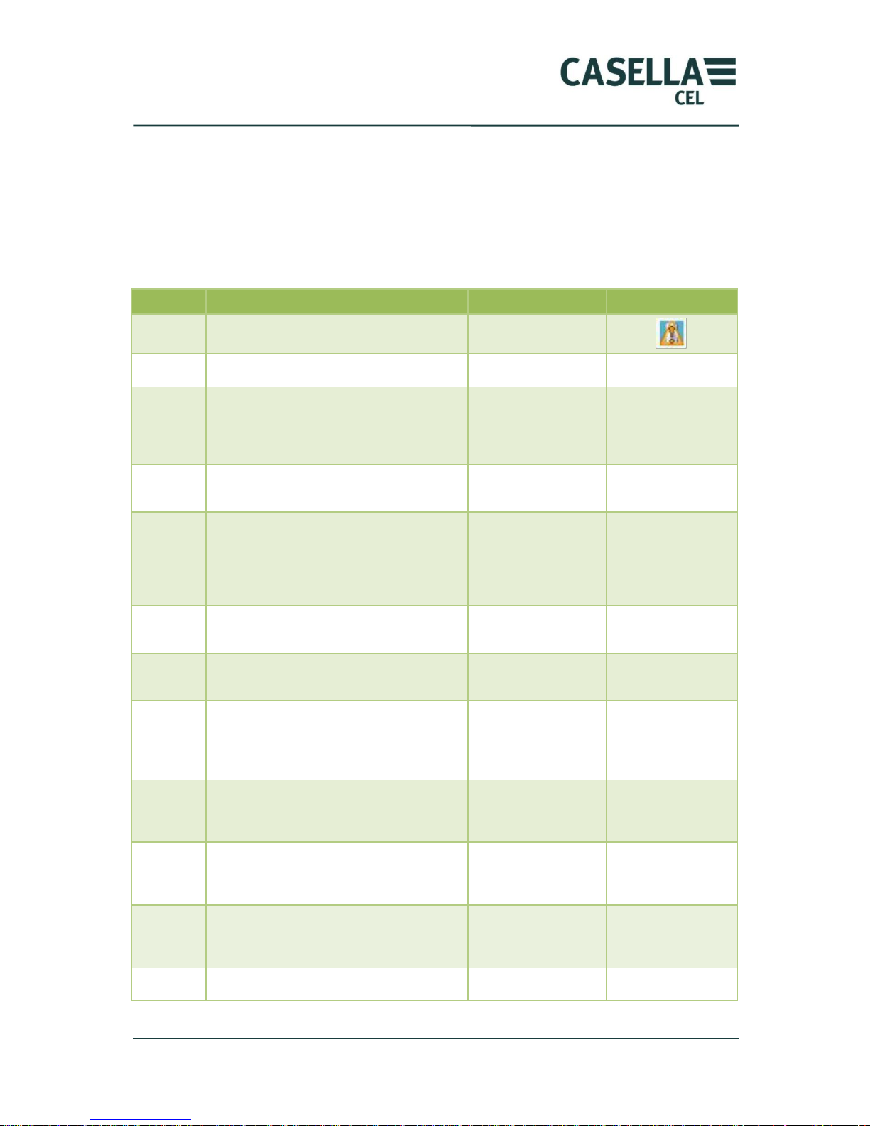
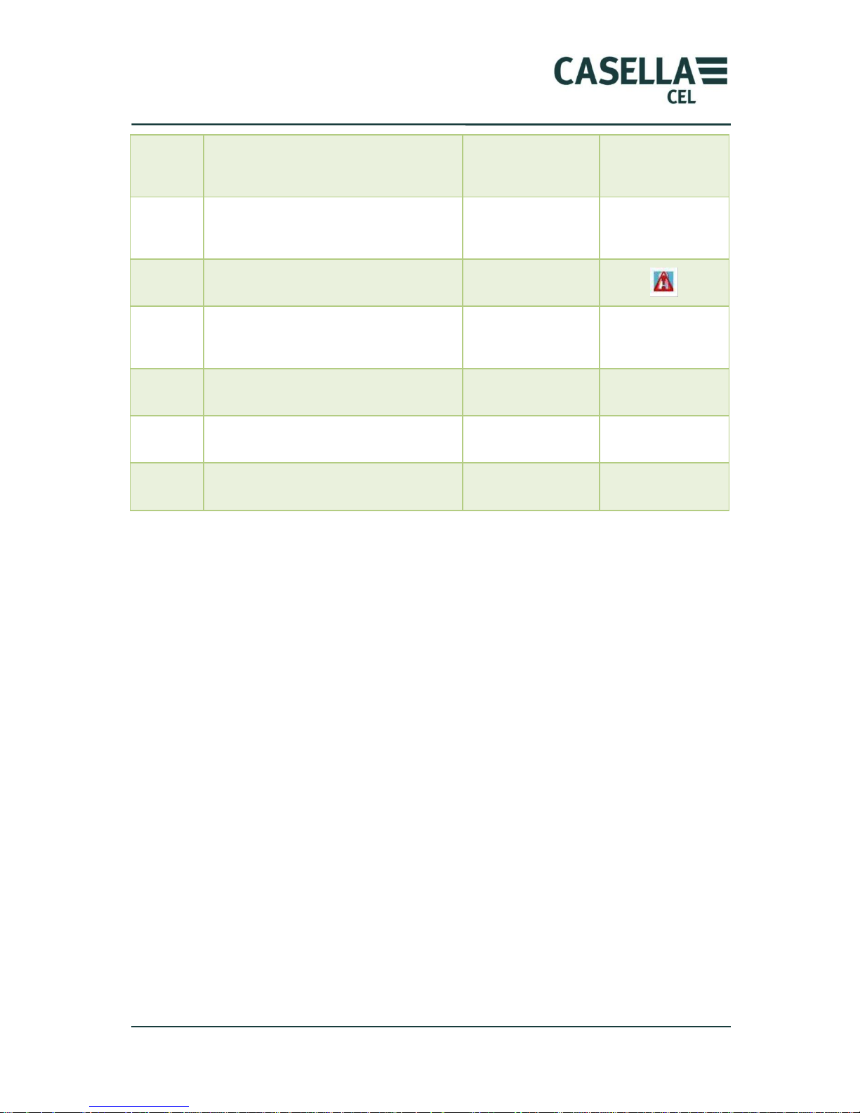
dB96 may display alarms generated by CEL-960, which are more or less explicit.
Errors are numbered and can be cross referenced with the table below to
understand the nature of the issue. Some of the errors below indicate and major
fault, meaning the instrument will need to be returned for repair to our customer
service department.
Number
Name
Description
Comments
1
ALARM_LOW_BAT
Low battery
2
ALARM_MEMORY_FULL
Full memory
4
ALARM _FAILURE_END_MEASURE
Measurement stop
error
Measurement
ended before
normal time
(watchdog)
8
ALARM_SYSTEM_CMX
CMX problem
System problem,
real-time kernel
16
ALARM_PB_MEASURE
Measurement
problem: cannot
stop real-time.
The measurement
task does not take
into account the
measurement stop
command.
32
ALARM_QUEUE_ FULL
Measurement/stora
ge writing file is full
64
ALARM_PB_CODEC
Codec problem: no
samples received
128
ALARM_FAILURE_READ_CONFIG_A
T_START
Error while reading
configuration
Reading failed for
a configuration file
on SD card or flash
at start
252
ERR_SENDDATABLOCK
Error while sending
data
Occurs when
downloading a
new version
253
ERR_STARTUPGRADE
Cannot start
download
Occurs when
downloading a
new version
254
ERR_OPENFILE
Problem while
opening file
Occurs when
downloading a
new version
255
ERR_UNDEF
Generic error
During download
Page 49
CEL-960 Human Vibration Meter
49 Casella CEL
256
ALARM_CONFLIT_SDCARD_CODEC
SDCARD codec
conflict for SPI
access
512
ALARM_COM_BOARD_TEST
Test card
communication
problem
1024
ALARM_VERY_LOW_BAT
Very low battery
alarm
2048
ALARM_SUPPLY_CONSO
Battery problem or
analogue voltage or
consumption alarm
4096
ALARM_ACCES_SDCARD
Problem accessing
SD card
8192
ALARM_TIMOUT_TX_BT
Timeout on TX of
BT
16384
ALARM_ADC_ARM
Problem reading
ADC of ARM
Page 50
CEL-960 Human Vibration Meter
50 Casella CEL
7 Technical specifications
7.1 Standards
ISO 8041 (2005).
ETSI EN 300 328 V1.5.1 (2004)
NF EN 61000-6-1 NF EN 61000-6-2 NF EN 61000-6-3 NF EN 61000-6-4
(2001)
EN 61010-1 (2001)
7.2 Metrology
Whole body mode
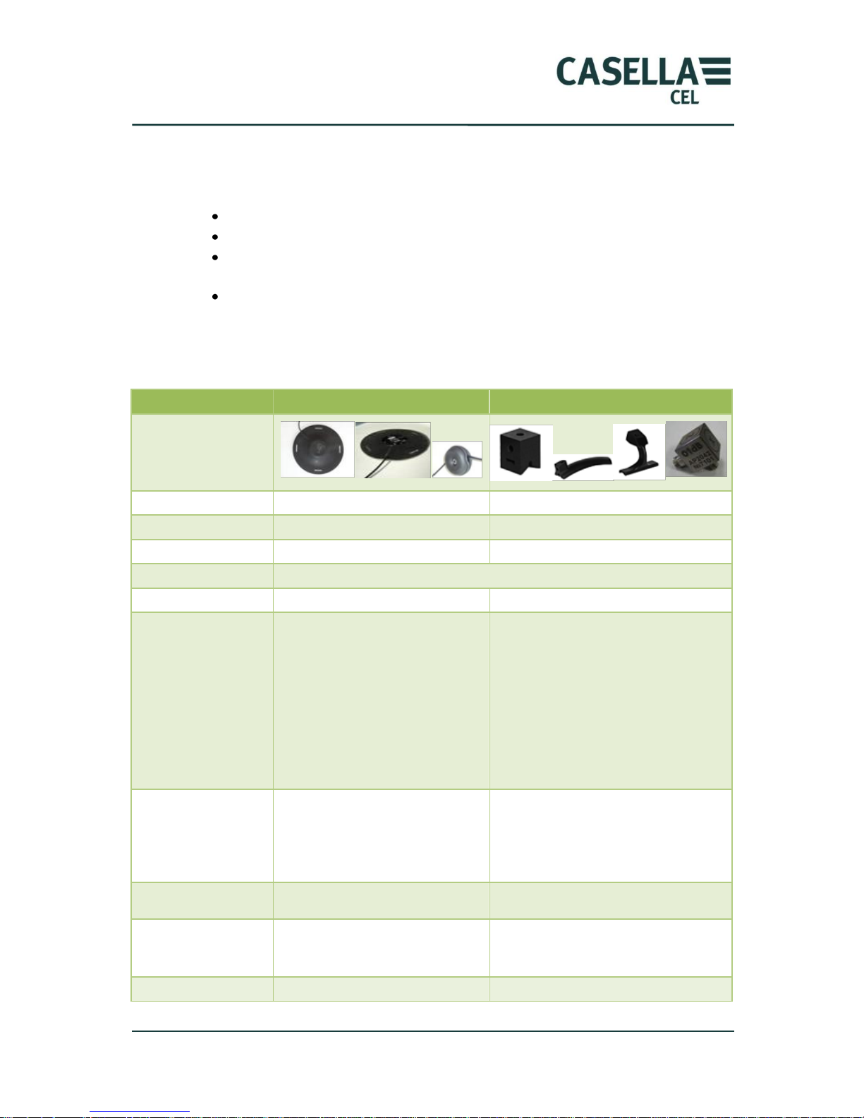
Hand arm mode
Linearity domain
75 dB
75 dB
Dynamic range
0.04-120 m/s²
0.5-3000 m/s²
Frequency weightings
Wd, Wk, 1/1, 1/3
Wh, 1/1, 1/3
Broad-band weighting
0.4 - 3700Hz
Display resolution
0.01
0.01
Recorded magnitudes
Band-pass acceleration
Weighted acceleration
Band-pass and weighted peak and
peak-to-peak acceleration
Peak factor
Equivalent acceleration
Daily exposure
Mobile RMS vibration MTVV
Vibration dose VDV
Seat efficiency SEAT (option)
Band-pass acceleration
Weighted acceleration
Band-pass and weighted peak and peak-to-
peak acceleration
Equivalent acceleration
Daily exposure
Configuration
Transducers
Units m/s², g
Integration time (IT)
Reference duration
Time constant
Transducers
Units m/s², g
Integration time (IT)
Reference duration
Alarm, overload
counting
Yes
Yes
Calculated magnitudes
Av, aeq, A(8), A(8)v, VDV, Fc, MTVV
SEAT(option)
Measurement time, calculation time
Av, A(8)
Measurement time
Integration time
From 1s to 60s by steps of 1s
From 1s to 60s by steps of 1s
Page 51
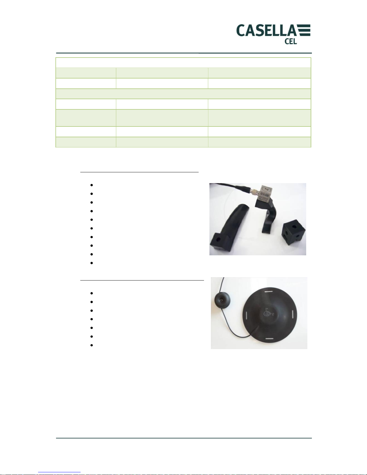
CEL-960 Human Vibration Meter
51 Casella CEL
Spectrum (option)
Octave
1 Hz - 2kHz
1 Hz - 2kHz
1/3 octave
0.8Hz- 2.5kHz
0.8Hz- 2.5kHz
Signal mode (option)
Sampling frequency
256-8192Hz
256-8192Hz
Pre-trigger
Depends on the calibration frequency
From 0 s to 16 s
Depends on the calibration frequency
From 0 s to 16 s
Maximum duration
-
-
Post-trigger
-
-
Operating temperature: -10°C / + 50°C (0-95% RH)
Hand arm transducer: CEL-960ACC3
Sensitivity 10mV/g.
Dynamic range 500g.
Bandwidth 1-1200Hz (-1dB).
Resonance frequency >36kHz.
Weight 13g.
Temperature range -40°C +125°C.
Output impedance <500 Ohms
Supply voltage +18 to 30V
Supply current 2 to 20mA
Noise level <0.002g
Whole body transducer: CEL-960ACC2
Sensitivity 115mV/g.
Dynamic range 18g.
Bandwidth 0-400Hz (-3dB).
Resonance frequency 24kHz.
Weight 35g.
Temperature range -40°C 105°C.
Cup equipped with a presence detector.
7.3 Memory module
1 GB Micro SD integrated Flash memory.
7.4 Battery
Lithium-Ion battery: Licell (3.7V 2AH).
Typical operating life:
Page 52
CEL-960 Human Vibration Meter
52 Casella CEL
Transducers
WBA001
WBA001 + DJB120
Other
Communication
Bluetooth OFF
17H
10H
10H
Communication
Bluetooth ON
15H
9H
9H
Charging time: 6h.
7.5 Physical characteristics
Dimensions: 100 mm * 55 mm * 25 mm.
Total weight: 140g.
IP53 protection.
7.6 Comment on the influence of the electromagnetic environment
As they are subjected to electrostatic discharges, measured level can be altered.
However, data recorded before and after the discharge are not altered.
Page 53
CEL-960 Human Vibration Meter
53 Casella CEL
8 Maintenance
No particular maintenance is required.
Before performing a series of measurements, the user must make sure that the
battery is correctly charged.
We recommend doing an Auto Test on a regular basis to ensure the CEL-960
instrument is operating without any faults.
8.1 Auto-Test
Refer to section 4.10.3 « Auto test ».
8.2 Disposal
In no event should the CEL-960 be thrown in a litter bin. It must be disposed of
according to the WEEE Directive*. A WEEE-compliant disposal and recycling
procedure should be applied.
(* WEEE: Waste from Electric and Electronic Equipment)
Page 54
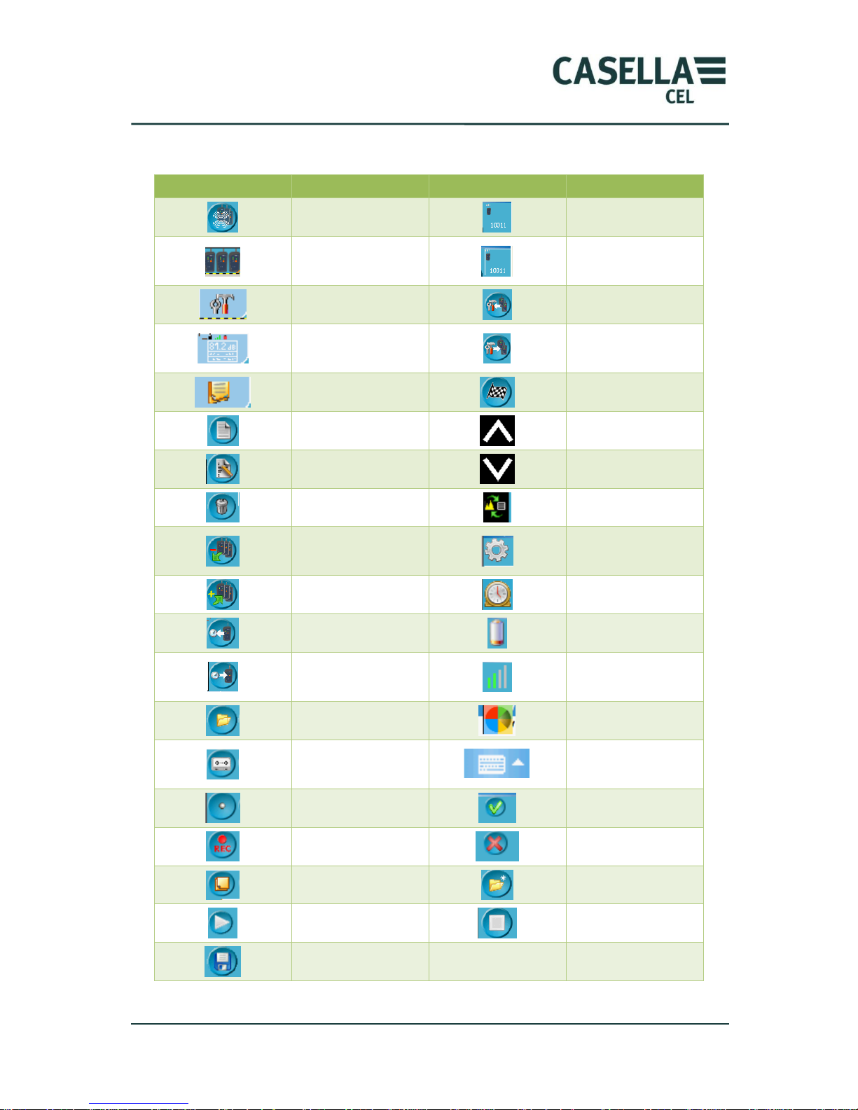
CEL-960 Human Vibration Meter
54 Casella CEL
9 Icons used in dB96 Control Software
Symbol
Explanation
Symbol
Explanation
Search CEL-960 over
the wireless network
CEL-960 is
unselected
Display all CEL-960
detected by the
wireless connection
CEL-960 selected
Go to measurement
configuration
Read measurement
configuration
Go to measurement
screen
Send measurement
configuration to CEL-
960
Go to comment screen
Activate configuration
Create configuration
Overload
Edit configuration
Under-load
Delete configuration
Icon for access to the
spectrum display
Remove CEL-960 from
the „workshop‟
Icon indicating that
CEL-960 is in storage
mode
Add CEL-960 to the
„workshop‟
Waiting for
measurement
Read internal clock of
CEL-960
Battery indicator
Send date and time to
internal clock of CEL-
960
Wireless connection
quality indicator
Select folder
Search for Bluetooth
instruments
Oral comment
Show or hide keyboard
at the bottom of input
screen
Coding 1, 2
Validate screen
Signal recording
Exit screen without
saving changes
Written comment
Create folder
Start calibration
Stop calibration
Save
Page 55
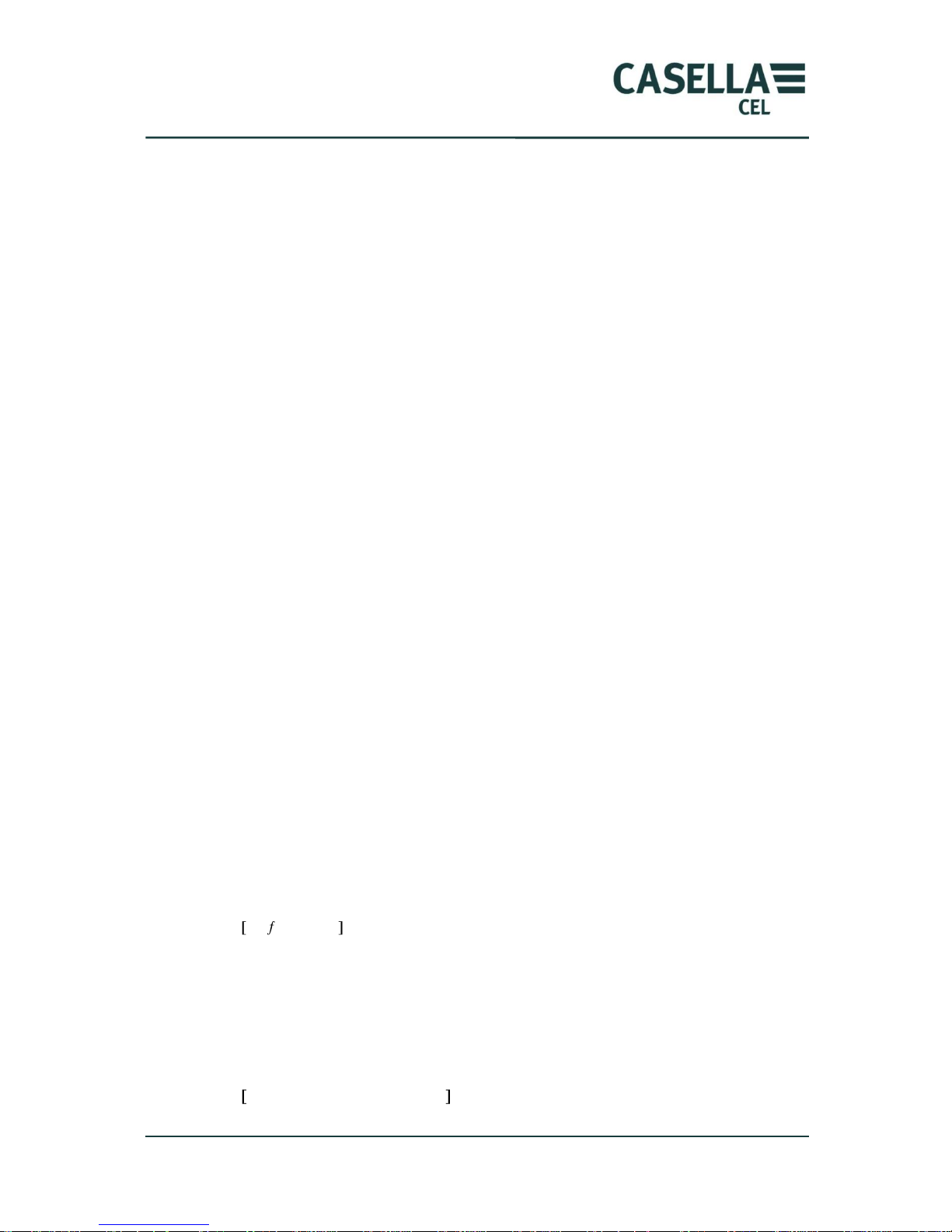
CEL-960 Human Vibration Meter
55 Casella CEL
10 Glossary of terms & formulae
10.1 Terms
a: Band limit frequency-weighted RMS acceleration in m/s²
ax: Band limit frequency-weighted RMS acceleration, x axis
ay: Band limit frequency-weighted RMS acceleration: y axis
az: Band limit frequency-weighted RMS acceleration: z axis
aw: Frequency-weighted RMS acceleration (Wd, Wk, Wh filter) in m/s²
awx: Weighted RMS acceleration, x axis
awy: Weighted RMS acceleration, y axis
awz: Weighted RMS acceleration, z axis
Filters:
Wh: Filter for hand arm measurements (valid for all 3 axes)
Wd: Filter for whole-body measurements (x and y axes)
Wk: Filter for whole-body measurements (z axis)
MTVV: Maximum value for the mobile RMS acceleration
Time constant: used for the calculation of mobile RMS acceleration
Time constant 125ms – time constant 1s – time constant 8s
VDV: Vibration dose in m/s
1.75
av: Overall whole-body vibration acceleration
aeq: Average overall whole-body vibration acceleration
ahv: Overall hand-arm vibration acceleration
A(8): Daily exposure value
SEAT: Seat efficiency factor
fc: Peak factor at the band limit
fwc: Frequency-weighted peak factor
Overall results: Results calculated over the entire period (av, ahv, aeq, A(8),…).
10.2 Formulae
aw: frequency-weighted RMS acceleration (Wd, Wk, Wh filters) in m/s²
a
w
= 1/T
0
T
a
w
2
(t) dt
1/2
with
a
w
(t): instant acceleration
T = measurement duration
av/aeq: overall whole-body vibration acceleration (m/s2)
av = (Kx awx)
2 +
(Ky awy)
2 +
(Kza
wz
2 )1/2
aeq = MAX (1.4 a
wx,
1.4 a
wy, awz
) if there is a predominant axis
Page 56
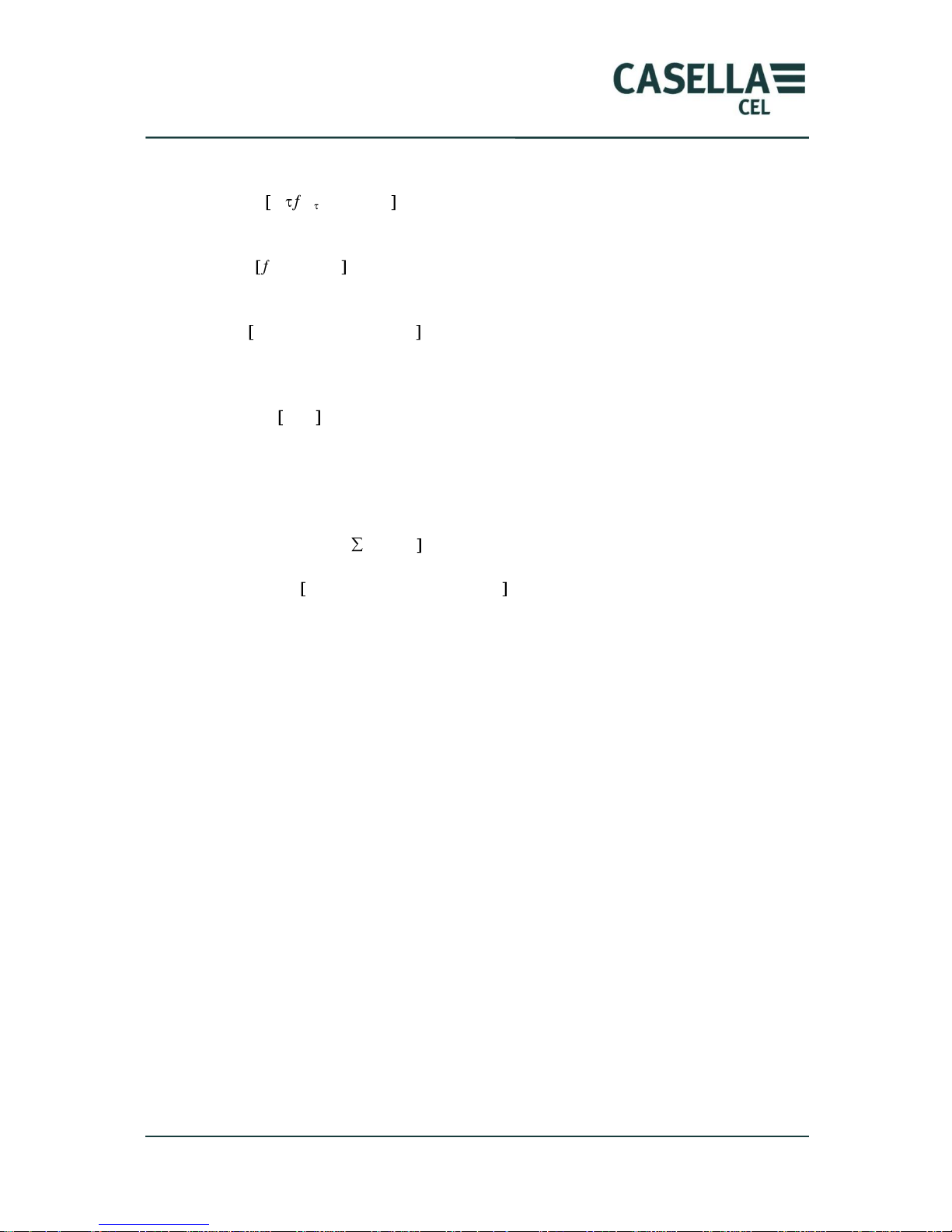
CEL-960 Human Vibration Meter
56 Casella CEL
MTVV: maximum value of mobile RMS acceleration
aw (t0)= 1/
t0-
t0
a
w
2
(t) dt
1/2
MTVV= max (aw(t0)) exponential integration
VDV: vibration dose in m/s
1.75
VDV=
0
T
a
w
4
(t) dt
1/4
ahv: overall hand-arm vibration acceleration
ahv = (a
hwx
)
2 +
(a
hwy
)
2 +
(a
hwz
2 )1/2
A(8): daily exposure to hand-arm vibrations (m/s2)
A(8)= ahv T/T
o
1/2
with T0= 28800s
A(8) / A(8)v: daily exposure to whole-body vibrations (m/s2)
A(8)=max[A(8)x, A(8)y, A(8)z]
with A(8)x= Kx[1/T0 a
wxi
²Ti
1/2
A(8)
v =
(T/T0 (Kx awx)
2 +
(Ky awy)
2 +
(Kza
wz
2
) )
1/2
with T0= 28800s, Kx=Ky=1.4 and Kz=1
SEAT: seat efficiency factor
SEAT= awz/awz2
with awz: acceleration on the seat, awz2: acceleration at the foot of the seat.
 Loading...