

Caselabs magnum tx10 Assembly Manual
MAGNUM TX10 Assembly Manual
(Single and Dual Systems)

Parts list:
Front Chassis Section with attached Front Cover - 1
Rear Chassis Section - 1
Top Chassis Section - 1
Bottom Chassis Section - 1
Mid-Chassis – 2
Divider – 1 (Single System) or 2 (Dual System)
Motherboard tray – 1 (Single System) or 2 (Dual System)
Cooling Chamber Covers – 4
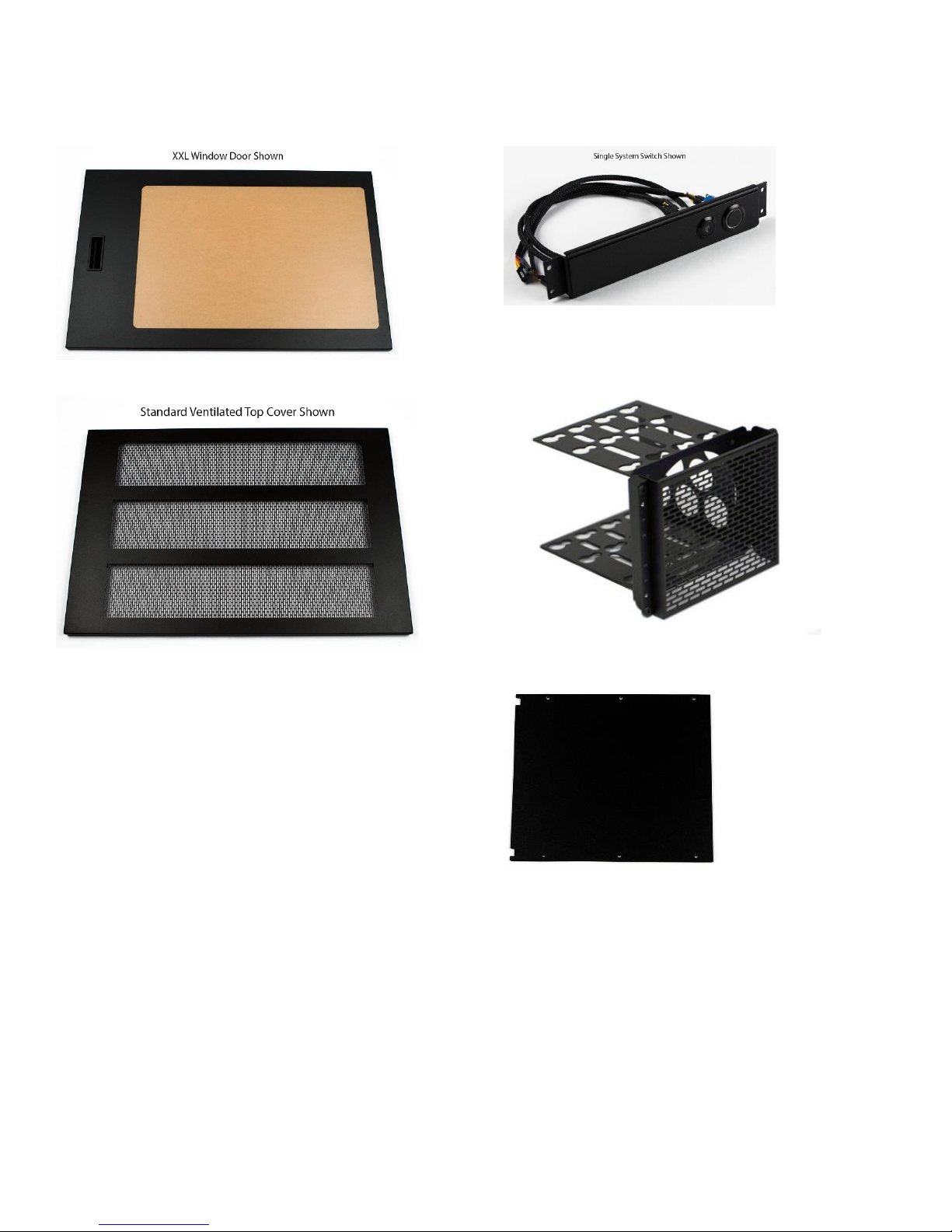
Doors – 2
Top Cover – 1
Switch Assembly – 1
Flex-Bay (5.25 bay) HDD Cage - 1 (Single System) or 2
(Dual System)
Flex-Bay Separator Plates - 4
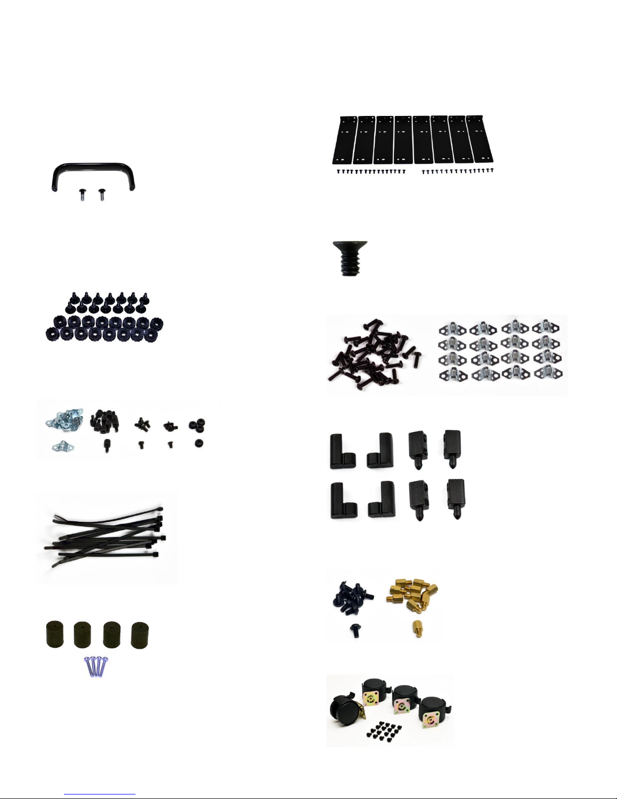
TX10 Assembly Kit:
Motherboard Tray Handel - 1 (Single System) or 2 (Dual
System)
Flex-Bay 5.25 Device Mounts – Standard – 4 sets
HDD Screw Mounting Kit - 1 (Single System) or 2 (Dual
System)
Spare Parts Kit – 1
Cable Ties – 10
Countersink Screws – 1 bag
Retention Clip kit – 1
Door Hinge Kit – 1
Tech Station Kit - 1 (Single System) or 2 (Dual System)
Motherboard Stand-offs - 1 (Single System) or 2 (Dual
System)
HD Casters – 1

Step 1.
Locate the Divider(s) and one Mid-Chassis. This step will determine motherboard placement and orientation. Please
follow the steps below based on how you would like the case to be configured.
Left and Right Sides
The TX10 has two different mounting locations for the divider which hold the motherboard in place, left and right
(determined when looking at the front of the case). The dividers are universal for both the left and right side.
The Mid-Chassis have two sets of mount holes down the middle of the parts. These holes are where the divider attaches
too. Mid-Chassis are universal for top and bottom.
 Loading...