

Case IH 1190, 1194, 1290, 1294, 1390 Shop Manual
...
SHOP MANUAL
www.maskinisten.net
CASE INTERNATIONAL
(DAVID BROWN)
MODELS
1190-1194-1290-1294-13901394-1490-1494-1594-1690
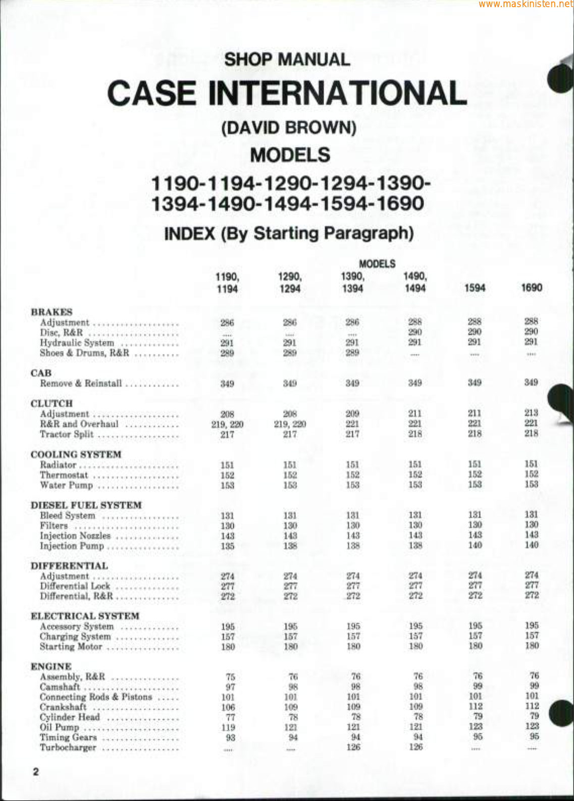
INDEX (By Starting Paragraph)
MODELS
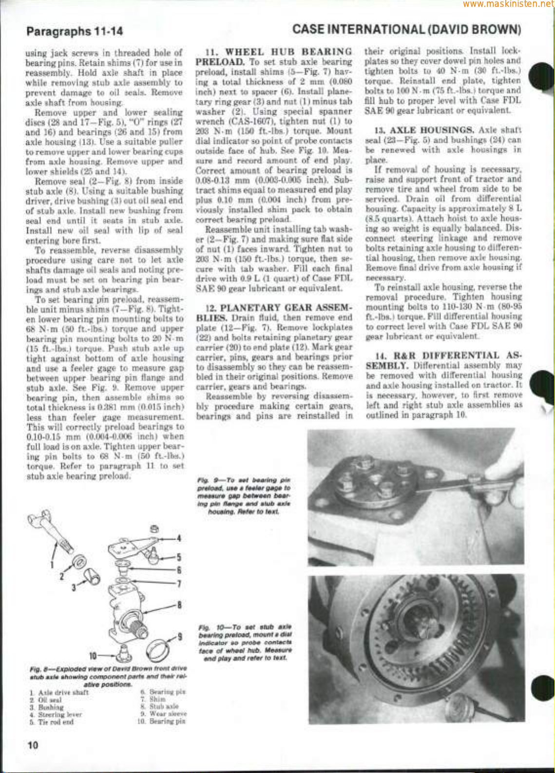
1190,
1194
1290,
1294
1390,
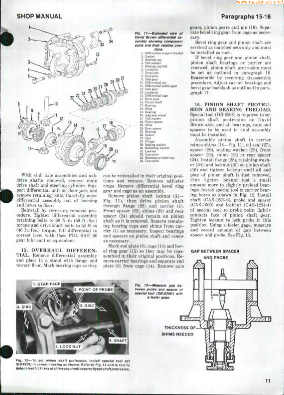
1394
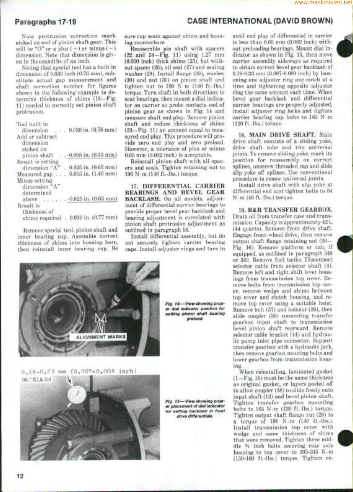
1490,
1494
1594
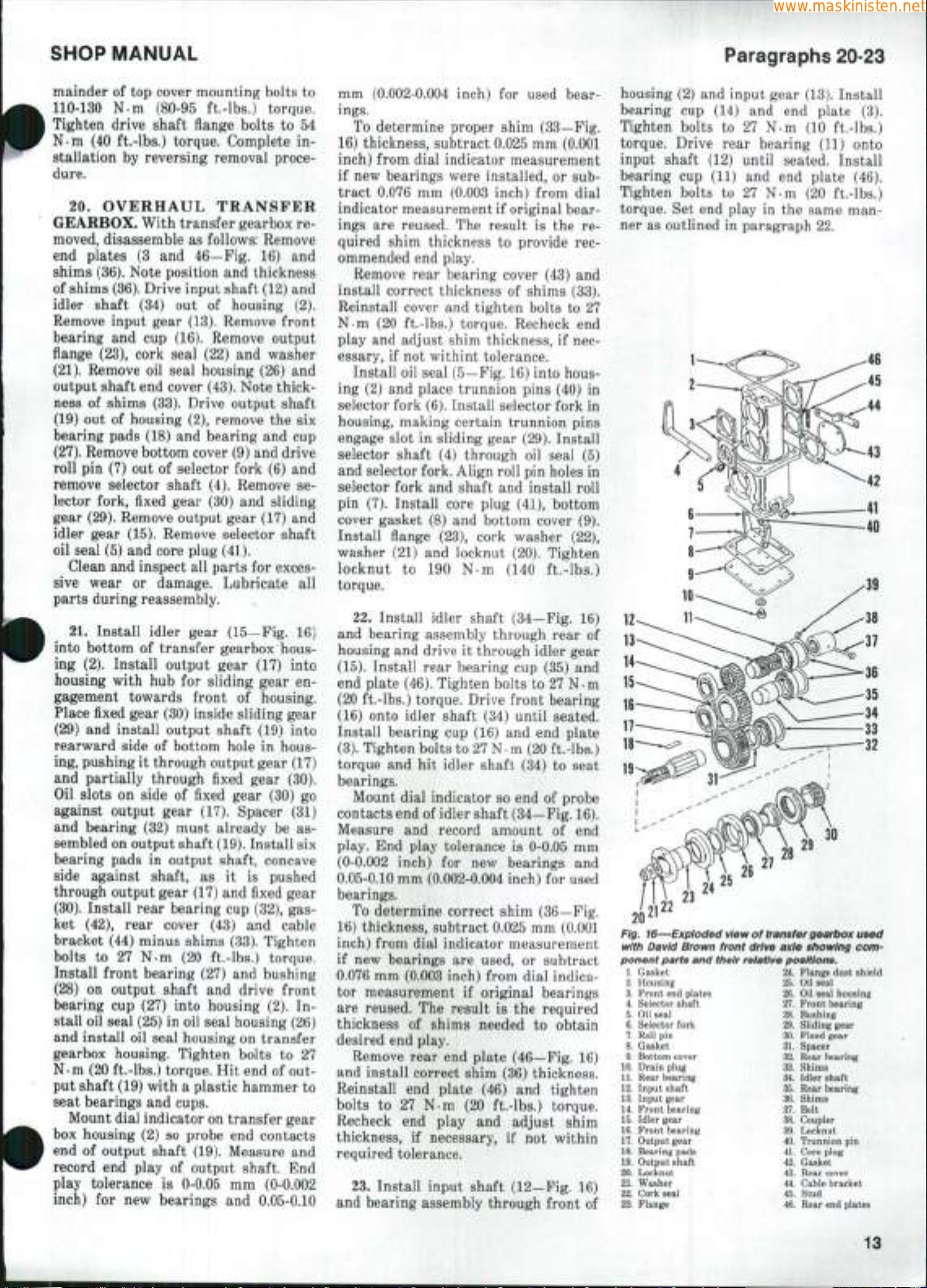
1690
BRAKES
Adjustment
Disc,
R&R
Hydraulic System
Shoes & Drums, R&R
CAB
Remove & Reinstall
CLUTCH
Adjustment
R&R and Overhaul
Tractor Split
COOLING SYSTEM
Radiator
Thermostat
Water Pump
DIESEL FUEL SYSTEM
Bleed System
Filters
Injection Nozzles
Injection Pump
DIFFERENTIAL
Adjustment
Differential Lock
Differential, R&R
291
289
34S
208
219,
217
151
m
15S
m
ISO
148
274
277
272
220
^^^ •
286
291
289
349
208
219,
217
151
152
153
131
130
143
138
274
277
272
220
286
291
289
349
209
221
217
151
152
153
131
130
143
138
274
277
.272
291
349
211
2ZL
218
%$l
162
IM
181
180
148
1%
274
277
272
288
290
291
349
211
221
218
151
152
153
131
130
143
140
274
277
272
288
290
291
349
213
221
218
151
152
153
131
130
143
140
274
277
272
ELECTRICAL SYSTEM
Accessory System
Charging System
Starting Motor
ENGINE
Assembly, R&R
Camshaft
Connecting Rods & Pistons
Crankshaft
Cylinder Head
Oil Pump
Timing Gears
Turbocharger
195
157
180
75
97
101
106
77
119
98
195
157
180
76
98
101
109
78
121
94
195
157
180
76
98
101
109
78
121
94
126
195
157
180
76
98
101
109
78
m
94
126
195
157
180
76
99
101
112
79
123
95
195
157
180
76
99
101
112
79
123
95
••*•
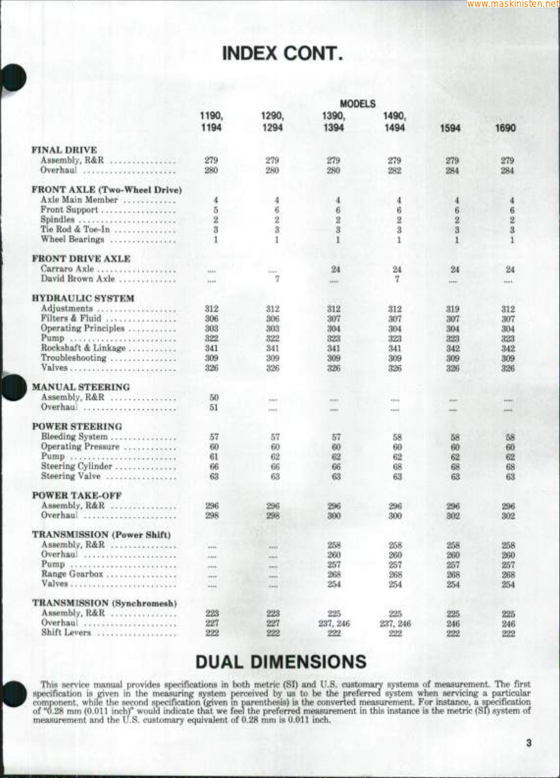
FINAL DRIVE
www.maskinisten.net
Assembly, R&R 2*79
Overhaul
280
FRONT AXLE (Two-Wheel Drive)
Axle Main Member 4
Front Support 5
Spindles 2
Tie Rod & Toe-in 3
Wheel Bearings 1
FRONT DRIVE AXLE
Carraro Axle
David Brown Axle
HYDRAULIC SYSTEM
Adjustments 312
Filters & Fluid 306
Operating Principles 303
Pump 322
Rockshai't & Linkage 341
Troubleshooting 309
Valves 326
INDEX CONT.
1190,
1194
1290,
1294
279
280
8
1
312
306
303
322
341
309
326
1390,
1394
279
280
4
6
2
3
1
24
312
307
304
323
341
309
326
MODELS
1490,
1494
279
282
24
7
312
307
304
323
341
309
326
1594
279
284
24
319
307
304
323
342
309
326
1690
279
284
4
6
2
3
1
4
6
2
a
1
24
312
307
304
323
342
309
326
MANUAL STEERING
Assembly, R&R 50
Overhaul 51
POWER STEERING
Bleeding System 57
Operating Pressure 60
Pump 61
Steering Cylinder 66
Steering Valve 63
POWER TAKE-OFF
Assembly, R&R 296
Overhaul 298
TRANSM][SSION (Power Shift)
Assembly, R&R
Overhaul
Pump
Range Gearbox
Valves
TRANSMISSION (Synchromesh)
Assembly, R&R 223
Overhaul 227
Shift Levers 222
57
60
62
66
63
296
298
57
60
62
66
63
296
300
258
260
257
268
....
223
227
222
254
225
237,
222
246
DUAL DIMENSIONS
296
300
258
260
257
268
254
225
237,
222
58
60
62
68
63
246
58
60
62
68
63
296
302
258
260
257
268
254
225
246
222
58
60
62
68
63
296
302
258
260
257
268
254
22S
246
222
This sendee manual provides specifications in both metric (SI) and U.S. customary systems of measurement. The first
specification is given in the measuring system perceived b^ us to be the preferred system when servicing a particular
component, while the second specification (given in parenthesis) is the converted measurement. For instance, a specification
of "0.28 mm (0.011 inch)" would indicate that we feel the preferred measurement in this instance is the metric (SI) system of
measuremtsnt and the IJ.S. customary equivalent of 0.28 mm is 0.011 inch.
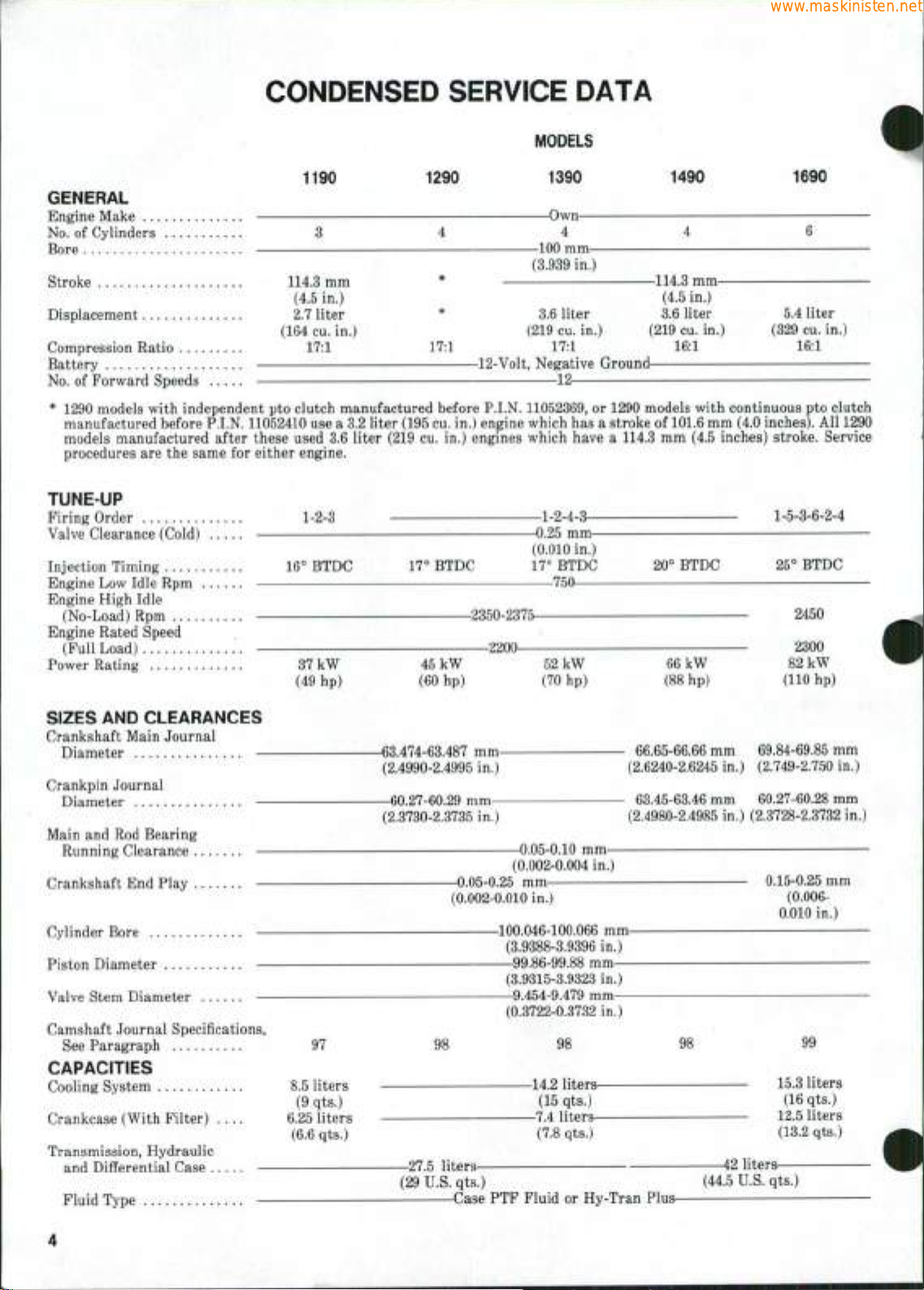
CONDENSED SERVICE DATA
www.maskinisten.net
MODELS
1190 1290 1390 1490 1690
GENERAL
Engine Make Own
No.
of Cylinders 3 4 4 4 6
Bore 100 mm
(3.939 in.)
Stroke 114.3 mm * 114.3 mm
Displacement 2.7 liter * 3.6 liter 3.6 liter 5.4 liter
Compression Ratio 17:1 17:1 17:1 16:1 16:1
Battery 12-Volt, Negative Ground
No.
of Forward Speeds 12
* 1290 models with independent pto clutch manufactured before P.I.N. 11052369, or 1290 models with continuous pto clutch
manufactured before P.I.N. 11052410 use a 3.2 liter (195 cu. in.) engine which has a stroke of 101.6 mm (4.0 inches). All 1290
models manufactured after these used 3.6 liter (219 cu. in.) engines which have a 114.3 mm (4.5 inches) stroke. Service
procedures are the same for either engine.
(4.5 in.) (4.5 in.)
(164 cu. in.) (219 cu. in.) (219 cu. in.) (329 cu. in.)
TUNE-UP
Firing Order
Valve Clearance (Cold)
Injection Timing
Engine Low Idle Rpm .
Engine High Idle
(No-Load) Rpm
Engine Rated Speed
(Full Load)
Power Rating
SIZES AND CLEARANCES
Crankshaft Main Journal
Diameter —
Crankpin Journal
Diameter —
Main and Rod Bearing
Running Clearance —
Crankshaft End Play —
Cylinder Bore —
Piston Diameter —
Valve Stem Diameter —
Camshaft Journal Specifications,
See Paragraph
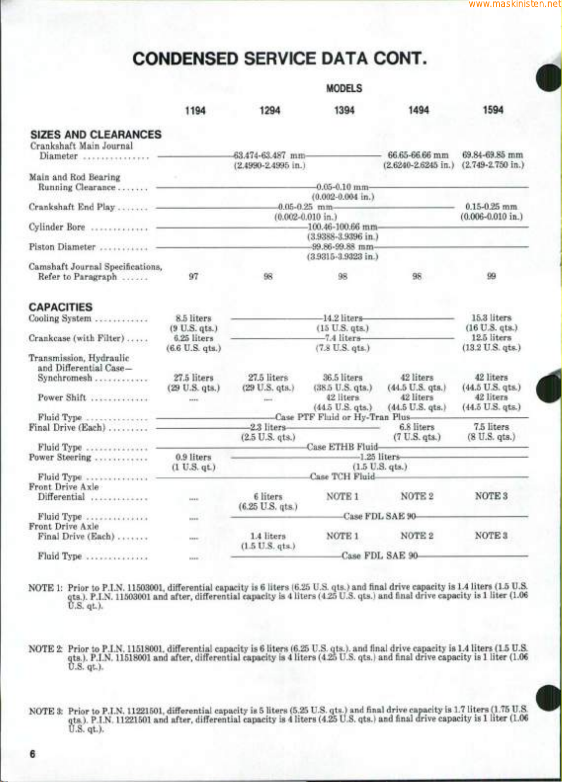
CAPACITIES
Cooling System ........
Crankcase (With Filter) ....
1-2-3
16° BTDC
37 kW
(49 hp)
97
8.5 liters
(9 qts.)
6.25 liters
(6.6 qts.)
17° BTDC
-2350-23752200—
45 kW
(60 hp)
-63.474-63.487 mm(2.4990-2.4995 in.)
—60.27-60.29 mm—
(2.3730-2.3735 in.)
—0.05-0.25 mm
(0.002-0.010 in.)
-100.046-100.066 mm—99.86-99.88 mm—
—9.454-9.479 mm—
98
-0.25 mm—
(0.010 in.)
17*^
BTDC
750
52 kW
(70 hp)
-0.05-0.10 mm(0.002-0.004 in.)
(3.9388-3.9396 in.)
(3.9315-3.9323 in.)
(0.3722-0.3732 in.)
98
-14.2 liters-
(15 qts.)
-7.4 liters-
(7.8 qts.)
1-5-3-6-2-4
20° BTDC 25° BTDC
2450
2300
66 kW
(88 hp)
- 66.65-66.66 mm 69.84-69.85 mm
(2.6240-2.6245 in.) (2.749-2.750 in.)
- 63.45-63.46 mm 60.27-60.28 mm
(2.4980-2.4985 in.) (2.3728-2.3732 in.)
98
82 kW
(110 hp)
0.15-0.25
(0.006-
0.010 in.)
99
15.3 liters
(16 qts.)
12.5 liters
(13.2 qts.)
mm
Transmission, Hydraulic
and Differential Case —
Fluid Type
-27.5 liters-
(29 U.S. qts.) (44.5 U.S. qts.)
Case PTF Fluid or Hy-Tran Plus
-42 liters-
CONDENSED SERVICE DATA CONT.
www.maskinisten.net
MODELS
1190
CAPACITIES (Cont)
Final Drive (Each)
Fluid Type
Power Ste€Ting 0.9 liters
(1 U.S. qt.)
Fluid Type
Manual Steering Gear 1.2 liters
(1.3 U.S. qts.)
Fluid Type Case FDL
SAE 140
Front Drive Axle Differential-
David Brown
Fluid Type
Carraro
Fluid Type
Front Drive Axle Final
Drive (Each)—
David Brown
Fluid Type
Carraro
Fluid Type
1290
-2.3 liters-
(2.5 U.S. qts.)
1390
ET HB Fiuid-
1.25 liters—
-Case
(8.5 U.S. qts.)
-Case FDL SAE 90-
-0.9 liters^
(1 U.S. qt.)
-Case FDL SAE 90-
(1.5 U.S. qts.)
TCH Fluid
-8 liters-
1490
6.8 liters
(7
U.S.
qts.)
-4 liters-
(4.25 U.S. qts.)
-Case FDL SAE 90-
-1.4 liters-
(1.5 U.S. qts.)
-Case FDL SAE 90-
1690
7.5 liters
(8 U.S. qts.)
1194 1294
GENERAL
Engine Make
No.
of Cylinders 3 4
Bore
Stroke
Displacement 2.7 liter
Compression Ratio 17:1
Battery
No.
of Forv/ard Speeds
TUNE-UP
Firing Order : . 1-2-3
Valve Clearance (Cold)
Injection Timing 16° BTDC 17° BTDC
Engine Lov/ Idle Rpm 750
Engine High Idle
(No-Load) Rpm
Engine Full Load Rpm
Power Rating 35 kW 45 kW
(164 cu. in.)
(49 hp) (62 hp)
17:1
MODELS
1394
Own
4
—100 mm—
(3.939 in.)
—114.3 mm—
(4.5 in.)
—3.6 liter—
(219 cu. in.)
-12 volts, Negative Ground12
—1-2-4-3
-0.25 mm
(0.010 in.)
IT BTDC 20^ BTDC 25° BTDC
-2350-2375-
-2200-
1-5-3-6-2-4
600-650
53 kW
(77 hp)
1494 1594
5.4 liter
(329 cu. in.)
2450
61 kW
(85 hp)
2300
72 kW
(97 hp)
CONDENSED SERVICE DATA
www.maskinisten.net
MODELS
CONT.
1194
SIZES
Crankshaft Main Journal
Main and Rod Bearing
Crankshaft End Play
Cylinder Bore
Piston Diameter
Camshaft Journal Specifications,
AND
CLEARANCES
Diameter
Running Clearance
Refer to Paragraph 97
CAPACITIES
Cooling System 8.5 liters
(9 U.S. qts.)
Crankcase (with Filter) 6.25 liters
(6.6 U.S. qts.)
Transmission, Hydraulic
and Differential Case—
Synchromesh 27.5 liters
(29 U.S. qts.)
Power Shift
Fluid Type
Final Drive (Each)
Fluid Type
Power Steering 0.9 liters
(1 U.S. qt.)
Fluid Type
Front Drive Axle
Differential .... :
Fluid Type
Front Drive Axle
Final Drive (Each)
Fluid Type
1294
-63.474-63.487 mm(2.4990-2.4995 in.)
-0.05-0.25 mm
(0.002-0.010 in.)
98
27.5 liters 36.5 liters 42 liters 42 liters
(29 U.S. qts.) (38.5 U.S. qts.) (44.5 U.S. qts.) (44.5 U.S. qts.)
Case PTF Fluid or Hy-Tran Plus-
-2.3 liters-
(2.5 U.S. qts.)
-Case ETHB Fluid-
6 liters
(6.25 U.S. qts.)
1.4 liters
(1.5 U.S. qts.)
1394
-0.05-0.10 mm-
(0.002-0.004 in.)
100.46-100.66 mm-
(3.9388-3.9396 in.)
99.86-99.88 mm—
(3.9315-3.9323 in.)
98
—14.2 liters—
(15 U.S. qts.)
—7.4 liters—
(7.8 U.S. qts.)
42 liters 42 liters 42 liters
(44.5 U.S. qts.) (44.5 U.S. qts.) (44.5 U.S. qts.)
1.25 liters—
(1.5 U.S. qts.)
-Case TCH Fluid
NOTE 1 NOTE 2
Case FDL SAE 90
NOTE 1 NOTE 2 NOTE 3
Case FDL SAE 90
1494 1594
- 66.65-66.66 mm
(2.6240-2.6245 in.)
98
6.8 liters
(7
U.S.
qts.)
69.84-69.85 mm
(2.749-2.750 in.)
0.15-0.25 mm
(0.006-0.010 in.)
15.3 liters
(16 U.S. qts.)
12.5 liters
(13.2
U.S.
7.5 liters
(8 U.S. qts.)
NOTE 3
qts.)
NOTE 1: Prior to P.I.N. 11503001, diflFerential capacity is 6 liters (6.25 U.S. qts.) and final drive capacity is 1.4 liters (1.5 U.S.
NOTE 2: Prior to P.I.N. 11518001, differential capacity is 6 liters (6.25 U.S. qts.). and final drive capacity is 1.4 liters (1.5 U.S.
NOTE
qts.).
P.I.N. 11503001 and after, differential capacity is 4 liters (4.25 U.S. qts.) and final drive capacity is 1 liter (1.06
U.S.
qt).
3ts.).
P.I.N. 11518001 and after, differential capacity is 4 liters (4.25 U.S. qts.) and final drive capacity is 1 liter (1.06
qts
•J.S.
qt.).
U.I
3:
Prior to P.I.N. 11221501, differential capacity is 5 liters (5.25 U.S. qts.) and final drive capacity is 1.7 liters (1.75 U.S.
:s.).
P.I.N. 11221501 and after, differential capacity is 4 liters (4.25 U.S. qts.) and final drive capacity is 1 liter (1.06
qts..
U.S.
qt).
FRONT AXLE
www.maskinisten.net
(TWO-WHEEL DRIVE)
Paragraphs
1-4
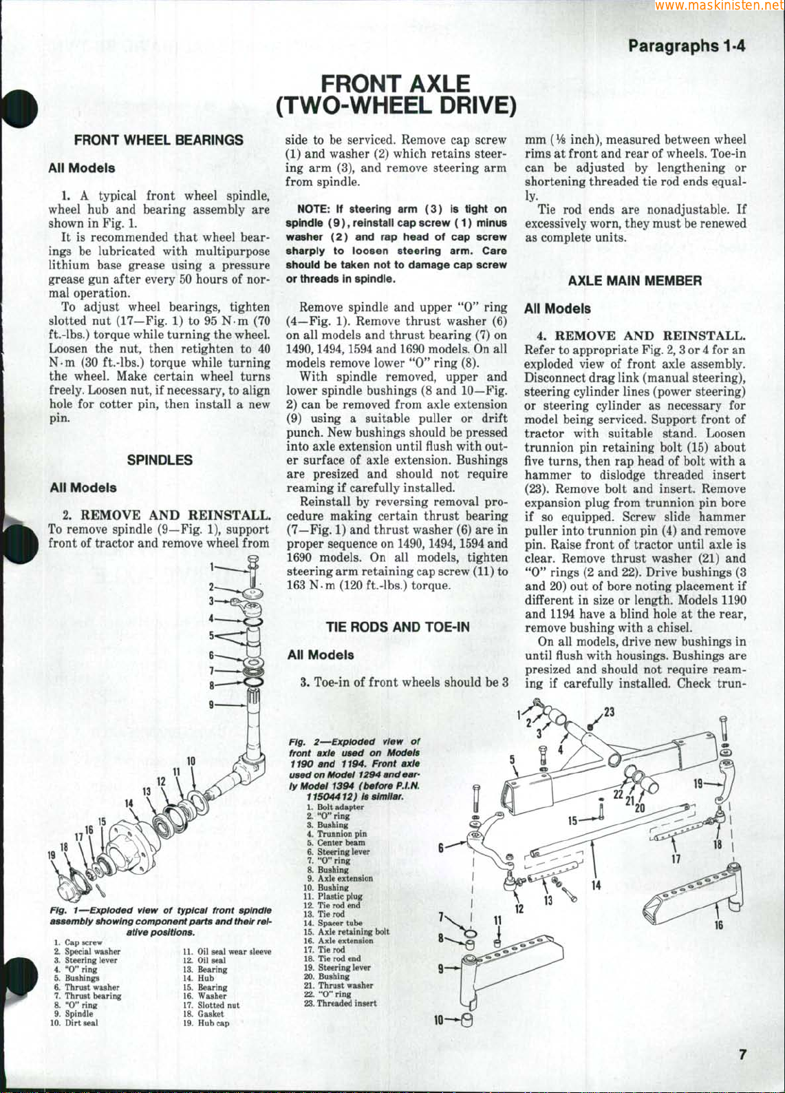
FRONT WHEEL BEARINGS
All Models
1. A typical front wheel spindle,
wheel
hub and
shown
in
It
is
recommended that wheel bear-
ings
be
lubricated with multipurpose
bearing assembly
Fig.
1.
are
lithium base grease using a pressure
grease gun after every 50 hours
of
nor-
mal operation.
To adjust wheel bearings, tighten
slotted
nut
(17—Fig.
1) to 95 N-m (70
ft.-lbs.) torque while turning the wheel.
Loosen
N-m
the nut,
(30
ft.-lbs.) torque while turning
then retighten
to 40
the wheel. Make certain wheel turns
freely. Loosen nut,
hole
for
cotter pin, then install
if
necessary, to align
a new
pin.
SPINDLES
All Models
2.
REMOVE
To remove spindle (9—Fig.
front
of
tractor and remove wheel from
AND
REINSTALL.
1),
support
side
to be
serviced. Remove
cap
screw
(1) and washer (2) which retains steering
arm
(3),
and
remove steering
from spindle.
NOTE:
spindie (9), reinstall cap screw (1) minus
washer (2) and rap head of cap screw
sharply to loosen steering arm. Care
should be taken not to damage cap screw
or threads in spindie.
Remove spindle
(4—Fig.
on
all
. •
If steering arm (3) is tight on
and
upper "0'^ ring
1).
Remove thrust washer
models and thrust bearing (7)
1490,1494,1594 and 1690 models. On
arm
(6)
on
all
models remove lower "0" ring (8).
With spindle removed, upper
lower spindle bushings
2)
can be
removed from axle extension
(8 and
(9) using a suitable puller
and
10—Fig.
or
drift
punch. New bushings should be pressed
into axle extension until flush with outer surface
are presized
reaming
Reinstall
of
axle extension. Bushings
and
should
if
carefully installed.
by
reversing removal
not
require
procedure making certain thrust bearing
(7—Fig. 1) and thrust washer (6)
are in
proper sequence on 1490,1494,1594 and
1690 models.
steering arm retaining cap screw (11)
On all
models, tighten
to
163 N-m (120 ft.-lbs.) torque.
TIE RODS AND TOE-IN
Alt Models
3,
Toe-in
of
front wheels should be
mm ( VB
rims
can
inch), measured between wheel
at
front and rear
be
adjusted
of
by
lengthening
wheels. Toe-in
shortening threaded tie rod ends equally.
Tie
rod
ends
are
nonadjustable.
excessively worn, they must be renewed
as complete units.
AXLE MAIN MEMBER
All Models
4.
REMOVE
AND
REINSTALL.
Refer to appropriate Fig. 2, 3 or 4 for
exploded view
of
front axle assembly.
Disconnect drag link (manual steering),
steering cylinder lines (power steering)
or steering cylinder
as
necessary
model being serviced. Support front
tractor with suitable stand. Loosen
trunnion
five
hammer
(23).
pin
retaining bolt (15) about
turns,
then
to
dislodge threaded insert
Remove bolt
rap
head
of
and
insert. Remove
bolt with
expansion plug from trunnion
if
so
equipped. Screw slide hammer
puller into trunnion pin (4) and remove
pin. Raise front
of
tractor until axle
clear. Remove thrust washer
"0"
rings (2 and 22). Drive bushings
and 20) out
different
and 1194 have a blind hole
of
bore noting placement
in
size
or
length. Models 1190
at the
remove bushing with a chisel.
On
all
models, drive new bushings
until flush with housings. Bushings
3
presized
ing
and
should
not
require ream-
if
carefully installed. Check trun-
or
If
an
for
of
a
pin
bore
is
(21) and
(3
if
rear,
in
are
Fig. 1—Exploded view of typical front spindle
assembly showing component parts and
1.
Cap screw
2.
Special washer
3.
Steering lever
4.
"0" ring
5.
Bushings
6. Thrust washer
7.
Thrust bearing
8. "0" ring
9. Spindle
10.
Dirt seal
ative positions.
^ 14.
'
16.
their
11.
Oil seat wear sleeve
12.
Oil seal
13.
Bearing
Hub
15.
Bearing
Washer
17.
Slotted nut
18.
Gasket
19.
Hubcap
Flg. 2—Exploded view
front axle used
i190
and
used on Model 1294 and early Model
rel-
if94. Front axle
1394
11504412) is
1.
Bolt adapter
2.
"0" ring
3.
Bushing
4.
Trunnion pin
5.
Center beam
6. Steering lever
7.
"0" ring
8. Bushing
9. Axle extension
10.
Bushing
U. Plastic plug
12.
Tie
rod end
13.
Tie
rod
14.
Spacer tube
15.
Axle retaining bolt
16.
Axle extension
17.
Tie
rod
18.
Tie
rod end
19.
Steering lever
20.
Bushing
21.
Thrust washer
22.
"O" ring
23.
Threaded insert
on
(before
similar.
of
Models
P.I.N.
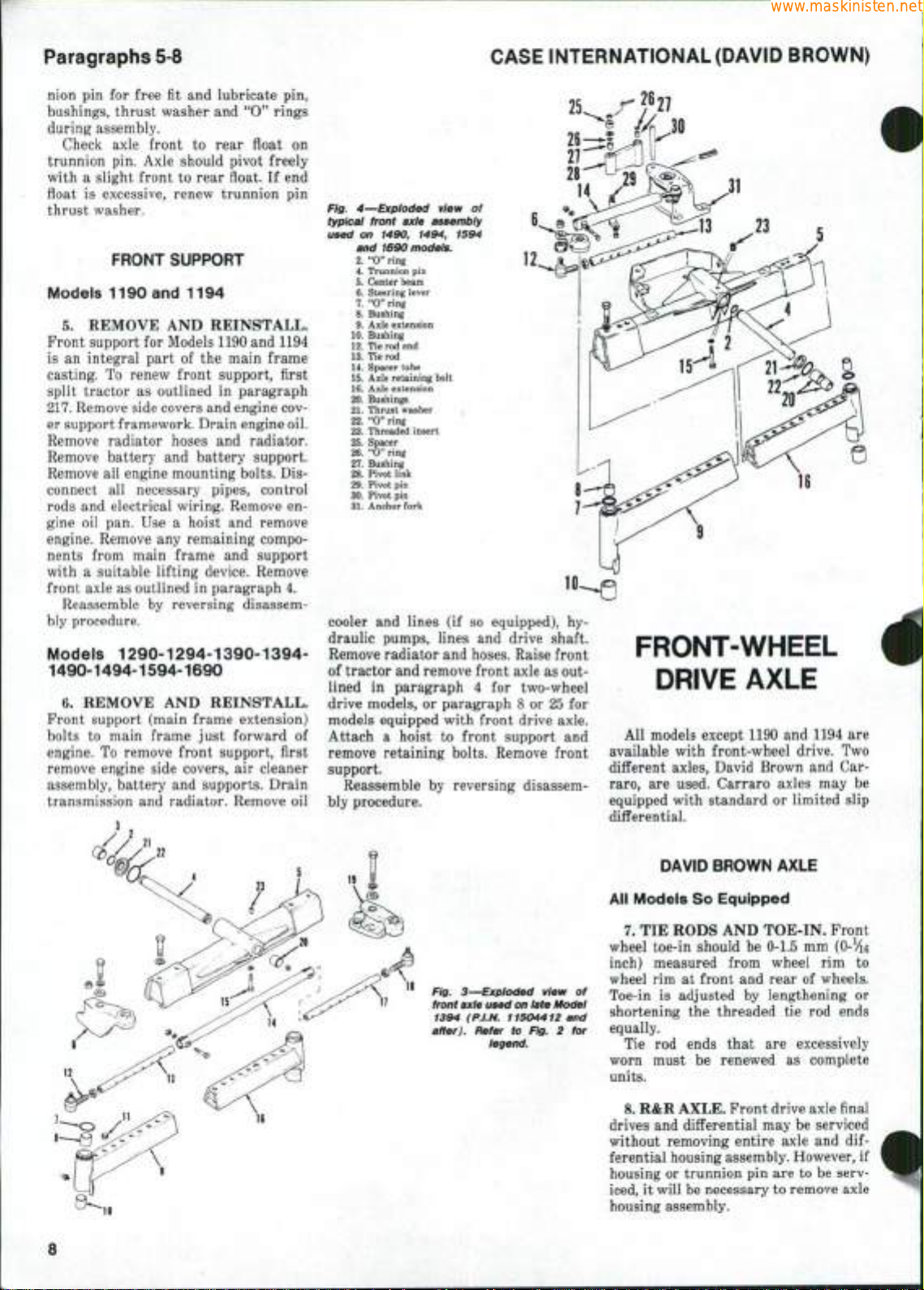
Paragraphs 5-8
www.maskinisten.net
CASE INTERNATIONAL (DAVID BROWN)
nion pin for free fit and lubricate pin,
bushings, thrust washer and "0" rings
during assembly.
Check axle front to rear fioat on
trunnion pin. Axle should pivot freely
with a slight front to rear float. If end
float is excessive, renew trunnion pin
thrust washer.
•
.
FRONT SUPPORT
Models 1190 and 1194
5.
REMOVE AND REINSTALL.
Front support for Models 1190 and 1194
is an integral part of the main frame
casting. To renew front support, first
split tractor as outlined in paragraph
217.
Remove side covers and engine cov-
er support framework. Drain engine oil.
Remove radiator hoses and radiator.
Remove battery and battery support.
Remove all engine mounting bolts. Disconnect all necessary pipes, control
rods and electrical wiring. Remove engine oil pan. Use a hoist and remove
engine. Remove any remaining components from main frame and support
with a suitable lifting device. Remove
front axle as outlined in paragraph 4.
Reassemble by reversing disassem-
bly procedure.
Models 1290-1294-1390-1394-
1490-1494-1594-1690
6. REMOVE AND REINSTALL.
Front support (main frame extension)
bolts to main frame just forward of
engine. To remove front support, first
remove engine side covers, air cleaner
assembly, battery and supports. Drain
transmission and radiator. Remove oil
25
Fig. 4—Exploded view of
typical front axle aBsembly
used on 1490, 1494, 1594
and 1690 models.
2.
"0"
ring
4.
Trunnion
5.
6.
7.
8.
9.
10.
12.
13.
14.
15.
16.
20.
21.
22.
23.
25.
26.
27.
2&.
29.
30.
31.
cooler and lines (if so equipped), hydraulic pumps, lines and drive shaft.
Remove radiator and hoses. Raise front
of tractor and remove front axle as outlined in paragraph 4 for two-wheel
drive models, or paragraph 8 or 25 for
models equipped with front drive axle.
Attach a hoist to front support and
remove retaining bolts. Remove front
support.
Reassemble by reversing disassem-
bly procedure.
pin
Center beam
Steering lever
"0"
Bushing
Axle extension
Bushing
Tie rod end
Tie rod
Spacer tube
Axle retaining bolt
Axle extension
Bushings
Thrust washer
"0"
Threaded insert
Spacer
"0"
Bushing
Pivot link
Pivot
Pivot
Anchor fork
ring
ring
ring
pin
pin
'
i
FRONT-WHEEL
DRIVE AXLE
All models except 1190 and 1194 are
available with front-wheel drive. Two
different axles, David Brown and Carraro,
are used. Carraro axles may be
equipped with standard or limited slip
differential.
4
Fig. 3—Exploded view of
front axle used on late Model
1394 (P.I.N. 11504412 and
after),
Refer to Fig. 2 for
legend.
DAVID BROWN AXLE
All Models So Equipped
7. TIE RODS AND TOE-IN. Front
wheel toe-in should be 0-1.5 mm
(0-We
inch) measured from wheel rim to
wheel rim at front and rear of wheels.
Toe-in is adjusted by lengthening or
shortening the threaded tie rod ends
equally.
Tie rod ends that are excessively
worn must be renewed as complete
units.
8. R&R AXLE. Front drive axle final
drives and differential may be serviced
without removing entire axle and differential housing assembly. However, if
housing or trunnion pin are to be serviced, it will be necessary to remove axle
housing assembly.
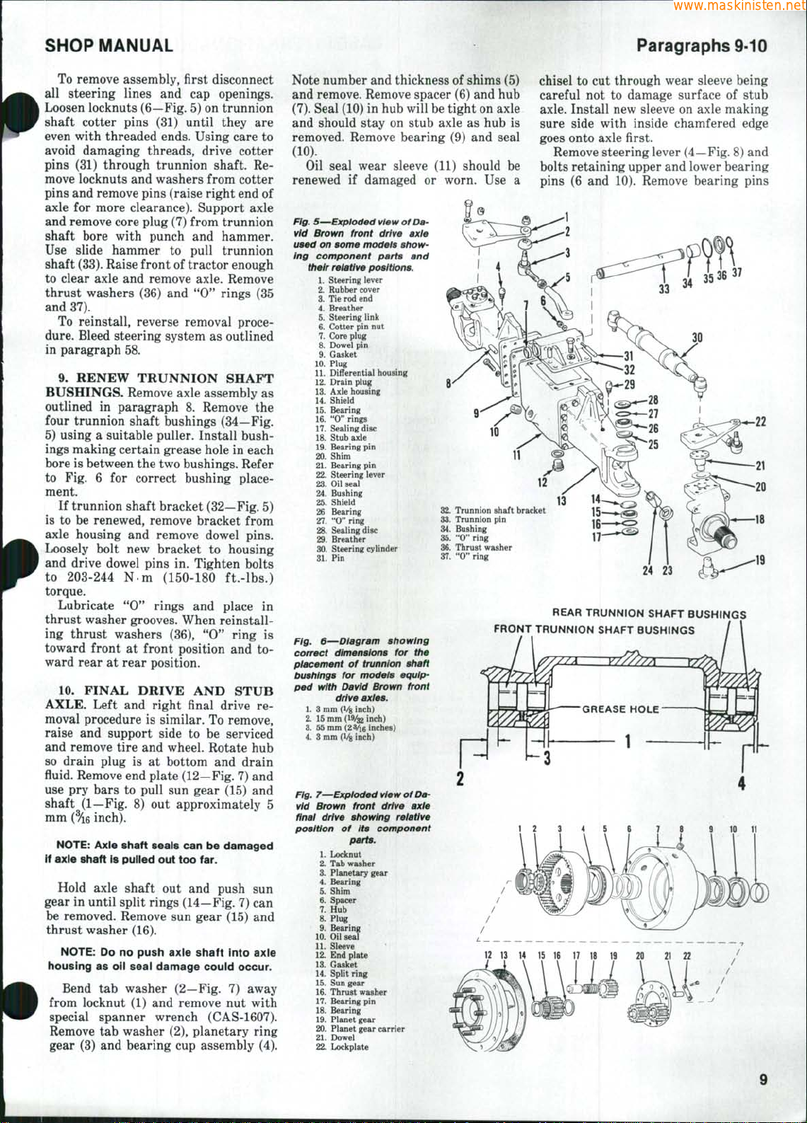
SHOP MANUAL
www.maskinisten.net
Paragraphs 9-10
To remove assembly, first disconnect
all steering lines and cap openings.
Loosen locknuts (6—Fig. 5) on trunnion
shaft cotter pins (31) until they are
even with threaded ends. Using care to
avoid damaging threads, drive cotter
pins (31) through trunnion shaft. Re-
move locknuts and washers from cotter
pins and remove pins (raise right end of
axle for more clearance). Support axle
and remove core plug (7) from trunnion
shaft bore with punch and hammer.
Use slide hammer to pull trunnion
shaft
(33).
Raise front of tractor enough
to clear axle and remove axle. Remove
thrust washers (36) and "0" rings (35
and 37).
To reinstall, reverse removal proce-
dure.
Bleed steering system as outlined
in paragraph 58.
9. RENEW TRUNNION SHAFT
BUSHINGS. Remove axle assembly as
outlined in paragraph 8. Remove the
four trunnion shaft bushings (34—Fig.
5) using a suitable puller. Install bushings making certain grease hole in each
bore is between the two bushings. Refer
to Fig. 6 for correct bushing placement.
If trunnion shaft bracket (32—Fig. 5)
is to be renewed, remove bracket from
axle housing and remove dowel pins.
Loosely bolt new bracket to housing
and drive dowel pins in. Tighten bolts
to 203-244 N-m (150-180 ft.-lbs.)
torque.
Lubricate "0** rings and place in
thrust washer grooves. When reinstalling thrust washers (36), "0" ring is
toward front at front position and toward rear at rear position.
10.
FINAL DRIVE AND STUB
AXLE.
Left and right final drive removal procedure is similar. To remove,
raise and support side to be serviced
and remove tire and wheel. Rotate hub
so drain plug is at bottom and drain
fluid. Remove end plate (12—Fig. 7) and
use pry bars to pull sun gear (15) and
shaft (1—Fig. 8) out approximately 5
mm
{%B
inch).
NOTE:
If axle shaft is pulled out too far.
Axle shaft seals can be damaged
Hold axle shaft out and push sun
gear in until split rings (14—Fig. 7) can
be removed. Remove sun gear (15) and
thrust washer (16).
NOTE:
housing as oil seal damage could occur.
Do no push axle shaft into axle
Bend tab washer (2—Fig. 7) away
from locknut (1) and remove nut with
special spanner wrench (CAS-1607).
Remove tab washer (2), planetary ring
gear (3) and bearing cup assembly (4).
Note number and thickness of shims (5)
and remove. Remove spacer (6) and hub
(7).
Seal (10) in hub will be tight on axle
and should stay on stub axle as hub is
removed. Remove bearing (9) and seal
(10).
Oil seal wear sleeve (11) should be
renewed if damaged or worn. Use a
Fig. 5—Expioded view of
vid Brown front drive axie
used on some models showing component parts and
their relative positions.
1.
Steering lever
2.
Rubber cover
3.
Tie
rod end
4.
Breather
5.
Steering link
6. Cotter pin nut
7.
Core plug
8. Dowel pin
9. Gasket
10.
Plug
11.
Differential housing
12.
Drain plug
13.
Axle housing
14.
Shield
15.
Bearing
16.
"0" rings
17.
Sealing disc
18.
Stub axle
19.
Bearing pin
20.
Shim
21.
Bearing pin
22.
Steering lever
23.
Oil seal
24.
Bushing
25.
Shield
26 Bearing
27.
"O" ring
28.
Sealing disc
29.
Breather
30.
Steering cylinder
31.
Pin
Fig. 6—Diagram showing
correct dimensions for the
placement of trunnion shaft
bushings for models equipped with David Brown front
drive axies.
1.
3 mm (l/g inch)
2.
15 mm (19/32 inch)
3.
55 mm {2 Vie inches)
4.
3 mm (Vg inch)
Fig. 7^Exploded view of
vid Brown front drive axie
finai drive showing reiative
position of its component
parts.
1.
Locknut
2.
Tab washer
3.
Planetary gear
4.
Bearing
5.
Shim
6. Spacer
7.
Hub
8. Plug
9. Bearing
10.
Oil seal
11.
Sleeve
12.
End plate
13.
Gasket
14.
Split ring
15.
Sun gear
16.
Thrust washer
17.
Bearing pin
18.
Bearing
19.
Planet gear
20.
Planet gear carrier
21.
Dowel
22.
Lockplate
Da-
Da-
2&.
Trunnion shaft bracket
33.
Trunnion pin
34.
Bushing
35.
"O"ring
36.
Thrust washer
37.
"0" ring
FRONT TRUNNION SHAFT BUSHINGS
12
13 14 15 16 17 18 19 20 21 22
chisel to cut through wear sleeve being
careful not to damage surface of stub
axle.
Install new sleeve on axle making
sure side with inside chamfered edge
goes onto axle first.
Remove steering lever (4—Fig. 8) and
bolts retaining upper and lower bearing
pins (6 and 10). Remove bearing pins
17
24
23
REAR TRUNNION SHAFT BUSHINGS
12
3 4 5 6 7 8 10 11
Paragraphs 11-14
www.maskinisten.net
CASE INTERNATIONAL (DAVID BROWN)
using jack screws
bearing pins. Retain shims (7)
reassembly. Hold axle shaft
while removing stub axle assembly
prevent damage
in
threaded hole
to oil
seals. Remove
for
in
of
use in
place
to
axle shaft from housing.
Remove upper
discs (28
and 16)
and
and
and
lower sealing
17-Fig. 5), "0" rings
bearings
(26 and
15) from
(27
axle housing (13). Use a suitable puller
to remove upper and lower bearing cups
from axle housing. Remove upper
and
lower shields (25 and 14).
Remove seal (2—Fig.
8)
from inside
stub axle (8). Using a suitable bushing
driver, drive bushing (3) out oil seal end
of stub axle. Install new bushing from
seal
end
until
it
seats
in
stub axle.
Install
new oil
seal with
lip of
seal
entering bore first.
To reassemble, reverse disassembly
procedure using care
not to let
axle
shafts damage oil seals and noting preload must
ings
To
be set on
and
stub axle bearings.
set
bearing pfin preload, reassem-
bearing
pin
bear-
ble unit minus shims (7—Fig. 8). Tighten lower bearing pin mounting bolts
68
N-m (50
bearing
ft.-lbs.) torque
pin
mounting bolts
and
to 20 N-m
(15 ft.-lbs.) torque. Push stub axle
tight against bottom
and
use a
feeler gage
between upper bearing
stub axle.
bearing
See Fig. 9.
pin,
then assemble shims
total thickness
of
axle housing
to
measure
pin
flange
Remove upper
is
0.381 mm (0.015 inch)
to
upper
up
gap
and
so
less than feeler gage measurement.
This will correctly preload bearings
0.10-0.15
mm
(0.004-0.006 inch) when
to
full load is on axle. Tighten upper bearing
pin
bolts
torque. Refer
to 68 N-m (50
to
paragraph
ft.-lbs.)
11 to set
stub axle bearing preload.
11.
WHEEL
PRELOAD.
preload, install shims (5—Fig.
ing a total thickness
inch) next
HUB
To set
BEARING
stub axle bearing
of 2 mm
to
spacer (6). Install plane-
7) hav (0.080
tary ring gear (3) and nut (1) minus tab
washer
(2).
Using special spanner
wrench (CAS-1607), tighten
203
N.m (150
ft.-lbs.) torque. Mount
dial indicator so point
outside face
sure
and
Correct amount
0.08-0.13
tract shims equal
plus
0.10 mm
of
hub.
See Fig. 10. Mea-
record amount
of
bearing preload
mm
(0.003-0.005 inch).
to
measured end play
(0.004 inch) from
viously installed shim pack
nut (1) to
of
probe contacts
of end
to
play.
is
Sub-
pre-
obtain
correct bearing preload.
Reassemble unit installing tab washer (2—Fig.
of
nut (1)
203
cure with
drive with 0.9 L (1 quart)
SAE 90 gear lubricant
12.
BLIES. Drain fluid, then remove
plate (12—Fig.
(22)
7)
and making sure flat side
faces inward. Tighten
N-m
(150 ft.-lbs.) torque, then
tab
washer. Fill each final
or
equivalent.
of
Case FDL
nut to
PLANETARY GEAR ASSEM-
7).
and
bolts retaining planetary gear
Remove lockplates
se-
end
carrier (20) to end plate (12). Mark gear
carrier, pins, gears
and
bearings prior
to disassembly so they can be reassembled
in
their original positions. Remove
carrier, gears and bearings.
Reassemble
by
reversing disassembly procedure making certain gears,
bearings
Fig.
preioad, use a feeier gage
measure gap between
ing pin fiange
and
pins
9—To
set
bearing
housing. Refer to
and
are
pin
to
bear-
stub axie
text.
reinstalled
in
their original positions. Install lockplates so they cover dowel pin holes and
tighten bolts
torque. Reinstall
bolts
to
fill hub
SAE 90 gear lubricant
13.
AXLE HOUSINGS, Axle shaft
seal (23—Fig.
be renewed with axle housings
to 40 N-m (30
end
plate, tighten
ft.-lbs.)
100 N m (75 ft.-lbs.) torque and
to
proper level with Case
or
equivalent.
5) and
bushings (24)
FDL
can
in
place.
If removal
raise
and
remove tire
serviced. Drain
housing. Capacity
(8.5 quarts). Attach hoist
ing
so
connect steering linkage
of
support front
and
weight
is
housing
wheel from side
oil
is
is
necessary,
of
tractor
and
to be
from differential
approximately 8
to
axle hous-
equally balanced. Dis-
and
remove
bolts retaining axle housing to differential housing, then remove axle housing.
Remove final drive from axle housing if
necessary.
To reinstall axle housing, reverse
the
removal procedure. Tighten housing
mounting bolts
to
110-130
N-m
(80-95
ft.-lbs.) torque. Fill differential housing
to correct level with Case FDL SAE
gear lubricant
14.
R&R
or
equivalent.
DIFFERENTIAL
SEMBLY. Differential assembly
90
AS-
may
be removed with differential housing
and axle housing installed on tractor.
is necessary, however,
left
and
right stub axle assemblies
outlined
in
paragraph 10.
to
first remove
It
as
L
flg^ S—Exploded view of
stub axle showing component parts and their rel-
1.
Axle drive shaft
2.
Oil seal
3.
Bushing
4.
Steering lever
5.
Tie rod end
10
10-
_ _
David Brown
ative positions.
front drive
6. Bearing pin
7.
Shim
8. Stub axle
9. Wear sleeve
10.
Bearing pin
Fig. 10—To
bearing preload, mount a dlai
indicator
face
end play and refer to
set
stub axle
so
probe contacts
of
wheel hub. Measure
text.
SHOP MANUAL
www.maskinisten.net
With stub axle assemblies
drive shafts removed, remove main
drive shaft
port diflferential unit
and
steering cylinder. Sup-
on
remove retaining bolts. Carefully move
differential assembly
and lower
Reinstall
to
by
floor.
out of
reversing removal
cedure. Tighten differential assembly
retaining bolts
torque
and
to 68 N m (50
drive shaft bolts
(40 ft.-lbs.) torque. Fill differential
correct level with Case
gear lubricant
15.
OVERHAUL DIFFEREN-
or
equivalent.
TIAL. Remove differential assembly
and place
in a
stand with flange
toward floor. Mark bearing caps so they
and
axle
floor jack
and
housing
pro-
ft.-lbs.)
to
54
N m
to
FDL SAE 90
end
Fig. 11—Exploded view
David Brown differentiai
sembiy showing component
parts
and
their relative
tions.
1.
Differential support bracket
2.
Gasket
3.
Bearing
cap
4.
Tab
washer
5.
Bearing
cap
pin
plate
washer
screw
screw
bolt
pin
6.
Lockplate
7.
Dowel
8.
End
9.
Side gear
10.
Differential
11.
Differential pinion gear
12.
Side gear
13.
Lockplate
14.
Differential cage
15.
Bevel gear
16.
Pinion shaft
17.
Bearing
18.
Shim
19.
Bearing
20.
Adjuster wheel
21.
Tab
22.
Front spacer
23.
Shim
24.
Rear spacer
25.
Bearing
26.
Spacer
27.
Seal
28.
Flange
29.
Sealing washer
30.
Retaining washer
31.
Locknut
32.
Cap
33.
Steering cylinder
34.
Cap
cap
of
as-
posi-
can be reinstalled in their original positions
and
rings.
gear and cage
Remove pinion shaft locknut
Fig.
through flange
Front spacer (22), shims (23)
spacer
shaft
ing bearing cups
rier
and spacers
remove. Remove adjuster
Remove differential bevel ring
as an
assembly.
(31 —
11),
then drive pinion shaft
(28) and
carrier
and
(24)
as it is
removed. Remove remain-
and
(1) as
necessary. Inspect bearings
on
pinion shaft
should remain
on
pinion
shims from
and
renew
(1).
rear
car-
as necessary.
Mark end plate (8), cage (14) and bevel ring gear (15)
sembled
in
so
they
may be
reas-
their original positions. Remove carrier bearings and separate end
plate
(8)
from cage (14). Remove axle
Paragraphs 15-16
gears,
pinion gears
rate bevel ring gear from cage as neces-
sary.
Bevel ring gear
serviced
be installed
as
matched sets only and must
as
If bevel ring gear
pinion shaft bearings
renewed, pinion shaft protrusion must
be
set as
Reassemble
outlined
by
procedure. Adjust carrier bearings
bevel gear backlash as outlined in paragraph 17.
16.
PINION SHAFT PROTRU-
SION
AND
Special tool (DB-8208)
pinion shaft protrusion
Brown axle,
spacers
and all
to be
must be installed.
Assemble pinion shaft
minus shims (18—Fig. 11), oil seal (27),
spacer (26), sealing washer (29), front
spacer (22), shims
(24).
Install flange (28), retaining washer (30), and locknut (31) on pinion shaft
(16)
and
play
tighten locknut until
of
pinion shaft
then tighten locknut just a small
amount more
ings.
Install special tool
ing bores
as
shaft (CAS-1236-6), probe
(CAS-1609)
and
of special tool
contacts face
Tighten locknut
position. Using a feeler gage, measure
and record amount
spacer and probe. See Fig. 13.
GAP BETWEEN SPACER
AND PROBE
and pin
and
(10). Sepa-
pinion shaft
are
such.
and
pinion shaft,
or
in
paragraph
carrier
are
16.
reversing disassembly
and
BEARING PRELOAD.
is
required to set
on
bearings, cups
used
in
(23) or
final assembly
David
and
in
carrier
rear spacer
all end
is
just removed,
to
slightly preload bear-
in
shown
carrier bear-
in Fig. 12.
and
Install
spacer
locknut (CAS-1234-4)
so
probe point lightly
of
pinion shaft gear.
to
lock probe
of gap
in
this
between
Fig. 12—To set pinion shaft protrusion, install special tool set
iDB'8208)
determlnethicknessofshimsrequiredtocorrectlysetshaftprotrusion.
in carrier housing as
shown.
Refer
to Fig.
13
and to text to
Fig. 13—Measure
tween probe
special tool (DB-8208) with
a feeier gage.
gap be-
and
spacer
of
THICKNESS
SHIMS HEEDED
OF
11
Paragraphs 17-19
www.maskinisten.net
CASE INTERNATIONAL (DAVID BROWN)
Note protrusion correction mark
etched on end of pinion shaft gear. This
will be
*'O'*
or a plus ( + ) or minus
( —)
dimension. Note that dimension is given in thousandths of an inch.
Noting that special tool has a built in
dimension of 0.030 inch (0.76 mm), sub-
stitute actual gap measurement and
shaft correction number for figures
shown in the following example to determine thickness of shims (18—Fig.
11) needed to correctly set pinion shaft
protrusion.
Tool built in
dimension . .
0.030 in. (0.76 mm)
Add or subtract
dimension
etched on
pinion shaft .
-0.005 in. (0.13 mm)
Result is setting
dimension **A"
Measured gap . .
0.025 in.
0,055 in.
(0.63 mm)
(1.40 mm)
Minus setting
dimension "A"
determined
above -0.025 in. (0.63 mm)
Result is
thickness of
shims required . 0.030 in. (0.77 mm)
Remove special tool, pinion shaft and
inner bearing cup. Assemble correct
thickness of shims into housing bore,
then reinstall inner bearing cup. Be
0.18-0.23 mm (0.0()7-.O.OOQ inch)
sure cup seats against shims and housing counterbore.
Reassemble pin shaft with spacers
(22 and 24—Fig. 11) using 1.27 mm
(0.050 inch) thick shims (23), but without spacer (26), oil seal (27) and sealing
washer (29). Install flange (28), washer
(30) and nut (31) on pinion shaft and
tighten nut to 190 N m (140 ft-lbs.)
torque. Turn shaft in both directions to
seat bearings, then mount a dial indicator on carrier so probe contacts end of
pinion gear as shown in Fig. 14 and
measure shaft end play. Remove pinion
shaft and reduce thickness of shims
(23—Fig. 11) an amount equal to measured end play. This procedure will provide zero end play and zero preload.
However, a tolerance of plus or minus
0.05 mm (0.002 inch) is acceptable.
Reinstall pinion shaft with all spac-
ers and seals. Tighten retaining nut to
190 N-m (140 ft.-lbs.) torque.
17.
DIFFERENTIAL CARRIER
BEARINGS AND BEVEL GEAR
BACKLASH. On all models, adjust-
ment of differential carrier bearings to
provide proper bevel gear backlash and
bearing adjustment is correlated with
pinion shaft protrusion adjustment as
outlined in paragraph 16.
Install differential assembly, but do
not securely tighten carrier bearing
caps.
Install adjuster rings and turn in
Fig. 14—View
er dial indicator position for
setting pinion shaft bearing
Fig. 15—
er placement of dial
for setting
showing
preload.
View showing
drive differentials.
baciciash
indicator
prop-
prop-
in front
until end play of differential in carrier
is less than 0.05 mm (0.002 inch) without preloading bearings. Mount dial indicator as shown in Fig. 15, then move
carrier assembly sideways as required
to obtain correct bevel gear backlash of
0.18-0.23 mm (0.007-0.009 inch) by loosening one adjuster ring one notch at a
time and tightening opposite adjuster
ring the same amount each time. When
bevel gear backlash and differential
carrier bearings are properly adjusted,
install adjuster ring locks and tighten
carrier bearing cap bolts to 163 N-m
(120 ft.-lbs.) torque.
18.
MAIN DRIVE SHAFT. Main
drive shaft consists of a sliding yoke,
drive shaft tube and two universal
joints.
To remove sliding yoke, mark its
position for reassembly on correct
splines, unscrew threaded cap and slide
slip yoke off splines. Use conventional
procedure to renew universal joints.
Install drive shaft with slip yoke at
differential end and tighten bolts to 54
N-m (40 ft.-lbs.) torque.
19.
R&R TRANSFER GEARBOX.
Drain oil from transfer case and transmission. Capacity is approximately
42
(44 quarts). Remove front drive shaft.
Engage front-wheel drive, then remove
output shaft flange retaining nut (20—
Fig. 16). Remove platform or cab, if
equipped, as outlined in paragraph 348
or 349. Remove fuel tanks. Disconnect
selector cable from selector shaft (4).
Remove left and right shift lever housings from transmission top cover. Remove bolts from transmission top cov-
er, remove wedge and shims between
top cover and clutch housing, and remove top cover using a suitable hoist.
Remove bolt (37) and locknut (39), then
slide coupler (38) connecting transfer
gearbox input shaft to transmission
bevel pinion shaft rearward. Remove
selector cable bracket (44) and hydraulic pump inlet pipe connector. Support
transfer gearbox with a hydraulic jack,
then remove gearbox mouting bolts and
lower gearbox from transmission housing.
When reinstalling, laminated gasket
(1—Fig. 16) must be the same thickness
as original gasket, or layers peeled off
to allow coupler (38) to slide freely onto
input shaft (12) and bevel pinion shaft.
Tighten transfer gearbox mounting
bolts to 165 N-m (120 ft.-lbs.) torque.
Tighten output shaft flange nut (20) to
a torque of 190 N m (140 ft.-lbs.).
Install transmission top cover with
wedge and same thickness of shims
that were removed. Tighten three middle % inch bolts securing rear axle
housing to top cover to 205-245 N-m
(150-180 ft.-lbs.) torque. Tighten re-
L
12
SHOP MANUAL
www.maskinisten.net
Paragraphs 20-23
mainder of top cover mounting bolts to
110-130 N-m (80-95 ft.-lbs.) torque.
Tighten drive shaft flange bolts to 54
N-m (40 ft-lbs.) torque. Complete installation by reversing removal procedure.
20.
OVERHAUL TRANSFER
GEARBOX. With transfer gearbox re-
moved, disassemble as follows: Remove
end plates (3 and 46—Fig. 16) and
shims (36). Note position and thickness
of shims
(36).
Drive input shaft (12) and
idler shaft (34) out of housing (2).
Remove input gear (13). Remove front
bearing and cup (16). Remove output
flange
(23),
(21).
cork seal (22) and washer
Remove oil seal housing (26) and
output shaft end cover (43). Note thick-
ness of shims (33). Drive output shaft
(19) out of housing (2), remove the six
bearing pads (18) and bearing and cup
(27).
Remove bottom cover (9) and drive
roll pin (7) out of selector fork (6) and
remove selector shaft (4). Remove se-
lector fork, fixed gear (30) and sliding
gear (29). Remove output gear (17) and
idler gear (15). Remove selector shaft
oil seal (5) and core plug (41).
Clean and inspect all parts for exces-
sive wear or damage. Lubricate all
parts during reassembly.
21.
Install idler gear (15-Fig. 16)
into bottom of transfer gearbox housing (2). Install output gear (17) into
housing with hub for sliding gear engagement towards front of housing.
Place fixed gear (30) inside sliding gear
(29) and install output shaft (19) into
rearward side of bottom hole in housing, pushing it through output gear (17)
and partially through fixed gear (30).
Oil slots on side of fixed gear (30) go
against output gear (17). Spacer (31)
and bearing (32) must already be assembled on output shaft
(19).
Install six
bearing pads in output shaft, concave
side against shaft, as it is pushed
through output gear (17) and fixed gear
(30).
Install rear bearing cup (32), gasket (42), rear cover (43) and cable
bracket (44) minus shims (^33). Tighten
bolts to 27 N.m (20 ft.-lbs.) torque.
Install front bearing (27) and bushing
(28) on output shaft and drive front
bearing cup (27) into housing (2). Install oil seal (25) in oil seal housing (26)
and install oil seal housing on transfer
gearbox housing. Tighten bolts to 27
N-m (20 ft.-lbs.) torque. Hit end of output shaft (19) with a plastic hammer to
seat bearings and cups.
Mount dial indicator on transfer gear
box housing (2) so probe end contacts
end of output shaft (19). Measure and
record end play of output shaft. End
play tolerance is 0-0.05 mm (0-0.002
inch) for new bearings and 0.05-0.10
mm (0.002-0.004 inch) for used bearings.
To determine proper shim (33—Fig.
16) thickness, subtract 0.025 mm (0.001
inch) from dial indicator measurement
if new bearings were installed, or subtract 0.076 mm (0.003 inch) from dial
indicator measurement if original bearings are reused. The result is the re-
quired shim thickness to provide rec-
ommended end play.
Remove rear bearing cover (43) and
install correct thickness of shims (33).
Reinstall cover and tighten bolts to 27
N-m (20 ft.-lbs.) torque. Recheck end
play and adjust shim thickness, if necessary, if not withint tolerance.
Install oil seal (5—Fig. 16) into housing (2) and place trunnion pins (40) in
selector fork (6). Install selector fork in
housing, making certain trunnion pins
engage slot in sliding gear (29). Install
selector shaft (4) through oil seal (5)
and selector fork. Align roll pin holes in
selector fork and shaft and install roll
pin (7). Install core plug (41), bottom
cover gasket (8) and bottom cover (9).
Install flange (23), cork washer (22),
washer (21) and locknut (20). Tighten
locknut to 190 N-m (140 ft.-lbs.)
torque.
22.
Install idler shaft (34—Fig. 16)
and bearing assembly through rear of
housing and drive it through idler gear
(15).
Install rear bearing cup (35) and
end plate (46). Tighten bolts to 27 N-m
(20 ft.-lbs.) torque. Drive front bearing
(16) onto idler shaft (34) until seated.
Install bearing cup (16) and end plate
(3).
Tighten bolts to 27 N-m (20 ft.-lbs.)
torque and hit idler shaft (34) to seat
bearings.
Mount dial indicator so end of probe
contacts end of idler shaft (34—Fig. 16).
Measure and record amount of end
play. End play tolerance is 0-0.05 mm
(0-0.002 inch) for new bearings and
0.05-0.10 mm (0.002-0.004 inch) for used
bearings.
To determine correct shim (36—Fig.
16) thickness, subtract 0.025 mm (0.001
inch) from dial indicator measurement
if new bearings are used, or subtract
0.076 mm (0.003 inch) from dial indicator measurement if original bearings
are reused. The result is the required
thickness of shims needed to obtain
desired end play.
Remove rear end plate (46—Fig. 16)
and install correct shim (36) thickness.
Reinstall end plate (46) and tighten
bolts to 27 N-m (20 ft.-lbs.) torque.
Recheck end play and adjust shim
thickness, if necessary, if not within
required tolerance.
23.
Install input shaft (12—Fig. 16)
and bearing assembly through front of
housing (2) and input gear (13). Install
bearing cup (14) and end plate (3).
Tighten bolts to 27 N-m (10 ft.-lbs.)
torque. Drive rear bearing (11) onto
input shaft (12) until seated. Install
bearing cup (11) and end plate (46).
Tighten bolts to 27 N-m (20 ft.-lbs.)
torque. Set end play in the same manner as outlined in paragraph 22.
Fig. 16—Exploded view of transfer gearbox used
with David Brown front drive axle showing com-
ponent parts and their relative positions.
1.
Gasket
2.
Housing
3.
Front
end
4.
Selector shaft
5.
Oil
seal
6.
Selector fork
7.
Roll
pin
8.
Gasket
9.
Bottom cover
10.
Drain plug
11.
Rear bearing
12.
Input shaft
13.
Input gear
14.
Front bearing
15.
Idler gear
16.
Front bearing
17.
Output gear
18.
Bearing pads
19.
Output shaft
20.
Locknut
21.
Washer
22.
Cork seal
23.
Flange
\
plates
1
24.
Flange dust shield
25.
Oil
seal
26.
Oil
seal housing
27.
Front bearing
28.
Bushing
29.
Sliding gear
30.
Fixed gear
31.
Spacer
32.
Rear bearing
33.
Shims
34.
Idler shaft
35.
Rear bearing
36.
Shims
37.
Bolt
38.
Coupler
39.
Locknut
40.
Trunnion
41.
42.
Gasket
43.
44.
Cable bracket
45.
46.
Core plug
Rear cover
Stud
Rear
end
pin
plates
13
Paragraphs 24-27
www.maskinisten.net
CASE INTERNATIONAL (DAVID BROWN)
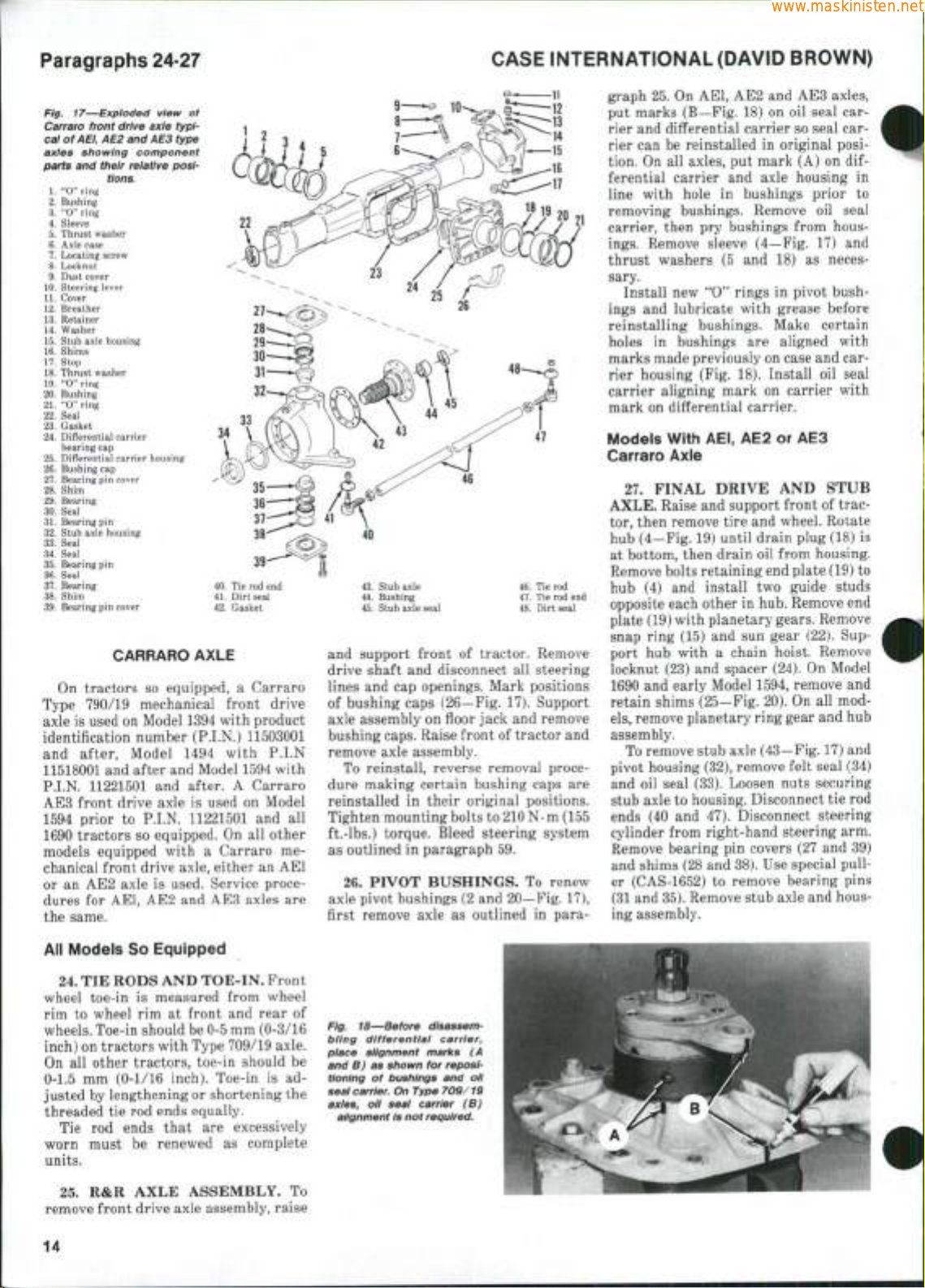
Fig. 17—Exploded view of
Carraro front drive axle typicai of
AEi,
AE2
and
AE3
,
type
40.
Tie rod end
41.
Dirt seal
42.
Gasket
axies showing component
parts and their reiative posi-
1.
"0"
2.
Bushing
3.
"0"
4.
Sleeve
5.
Thrust washer
6.
Axle case
7.
Locating screw
8.
Locknut
9.
Dust cover
10.
Steering lever
11.
Cover
12.
Breather
13.
Retainer
14.
Washer
15.
Stub axle housing
16.
Shims
17.
Stop
18.
Thrust washer
19.
"0"
20.
Bushing
21.
"0"
22.
Seal
23.
Gasket
24.
Differential carrier
25.
Differential carrier housing
26.
Bushing
27.
Bearing
28.
Shim
29.
Bearing
30.
Seal
31.
Bearing
32.
Stub axle housing
33.
Seal
34.
Seal
35.
Bearing
36.
Seal
37.
Bearing
38.
Shim
39.
Bearing
ring
ring
ring
ring
bearing
cap
cap
pin
pin
pin
pin
tions.
cover
cover
CARRARO AXLE
On tractors
so
equipped, a Carraro
Type 790/19 mechanical front drive
axle is used on Model 1394 with product
identification number (P.I.N.) 11503001
and after, Model
1494
with
P.I.N
11518001 and after and Model 1594 with
P.I.N. 11221501
AE3 front drive axle
1594 prior
1690 tractors
models equipped with a Carraro
chanical front drive axle, either
or
an
AE2 axle
dures
for
and
to
P.I.N. 11221501
so
equipped.
is
AEI, AE2
used. Service proce-
and
after. A Carraro
is
used
on
Model
and all
On all
other
me-
an
AEI
AE3 axles
are
the same.
43.
Stub axle
44.
Bushing
45.
Stub axle seal
and support front
drive shaft
lines
and
and
disconnect
cap openings. Mark positions
of
46.
Tie rod
47.
Tie rod end
48.
Dirt seal
tractor. Remove
all
steering
of bushing caps (26—Fig. 17). Support
axle assembly on floor jack and remove
bushing caps. Raise front of tractor and
remove axle assembly.
To reinstall, reverse removal procedure making certain bushing caps
reinstalled
Tighten mounting bolts to
in
their original positions.
210 N • m
are
(155
ft.-lbs.) torque. Bleed steering system
as outlined
26.
in
paragraph 59.
PIVOT BUSHINGS.
To
renew
axle pivot bushings (2 and 20—Fig. 17),
first remove axle
as
outlined
in
para-
graph 25.
put marks (B—Fig. 18)
On
AEI, AE2
and
on oil
AE3 axles,
seal
carrier and differential carrier so seal carrier can
tion. On
ferential carrier
line with hole
removing bushings. Remove
carrier, then
ings.
thrust washers
be
reinstalled
all
axles,
pry
in
original posi-
put
mark (A)
and
axle housing
in
bushings prior
bushings from hous-
Remove sleeve (4—Fig.
(5 and 18) as
on dif-
in
to
oil
seal
17) and
neces-
sary.
Install
new
ings
"0" rings
and
lubricate with grease before
in
pivot bush-
reinstalling bushings. Make certain
holes
in
bushings
are
aligned with
marks made previously on case and carrier housing (Fig.
carrier aligning mark
18).
Install
on
carrier with
oil
seal
mark on differential carrier.
Models With AEI, AE2
or
AE3
Carraro Axle
27.
FINAL DRIVE
AXLE.
Raise and support front
AND
STUB
of
tractor, then remove tire and wheel. Rotate
hub (4—Fig. 19) until drain plug (18)
is
at bottom, then drain oil from housing.
Remove bolts retaining end plate (19)
hub
(4) and
opposite each other
install
two
guide studs
in
hub. Remove end
to
plate (19) with planetary gears. Remove
snap ring (15)
port
hub
locknut (23)
1690
and
retain shims (25—Fig. 20). On
els,
remove planetary ring gear and hub
and sun
gear (22).
Sup-
with a chain hoist. Remove
and
spacer (24).
early Model 1594, remove
On
all
Model
and
mod-
assembly.
To remove stub axle (43—Fig. 17) and
pivot housing (32), remove felt seal (34)
and
oil
seal (33). Loosen nuts securing
stub axle
ends
to
(40 and
housing. Disconnect tie rod
47). Disconnect steering
cylinder from right-hand steering arm.
Remove bearing
pin
covers (27
and 39)
and shims (28 and 38). Use special puller (CAS-1652)
(31 and
35).
to
remove bearing pins
Remove stub axle and hous-
ing assembly.
All Models So Equipped
24.
TIE RODS AND TOE-IN. Front
wheel toe-in
rim
to
wheel
is
measured from wheel
rim at
front
wheels. Toe-in should be 0-5 mm (0-3/16
inch) on tractors with Type 709/19 axle.
On
all
other tractors, toe-in should
0-1.5
mm
(0-1/16 inch). Toe-in
justed by lengthening or shortening the
threaded
worn must
Tie
tie
rod ends equally.
rod
ends that
be
are
renewed
units.
25.
R&R
AXLE ASSEMBLY.
remove front drive axle assembly, raise
14
and
rear
is ad-
excessively
as
complete
of
Fig. 18—Before disassembiing differentiai carrier,
piace alignment marks (A
be
and B) as shown for repositioning of bushings and oil
seal
carrier.
axies, oil seal carrier (B)
aiignment is not required.
To
On Type 709/19
SHOP MANUAL
www.maskinisten.net
Paragraphs 28-29
12
3 4
8
9 10
18
19 20 21 22 23 24 25 26
11 12 13 14
Remove stub axle mounting nuts and
separate axle from pivot housing.
Remove bearing, thrust spacer, bushing
(44) and oil seal (45)
When reassembling, be sure lip
seal
is
towards inside
chamfered side
away from bearing. Heat bearings
120°C (25O''F) maximum prior
as
necessary.
of
of
stub axle
thrust spacer faces
of
oil
and
to
to in-
stallation.
To reinstall, reverse removal proce-
dure while noting that slot
in
stub axle
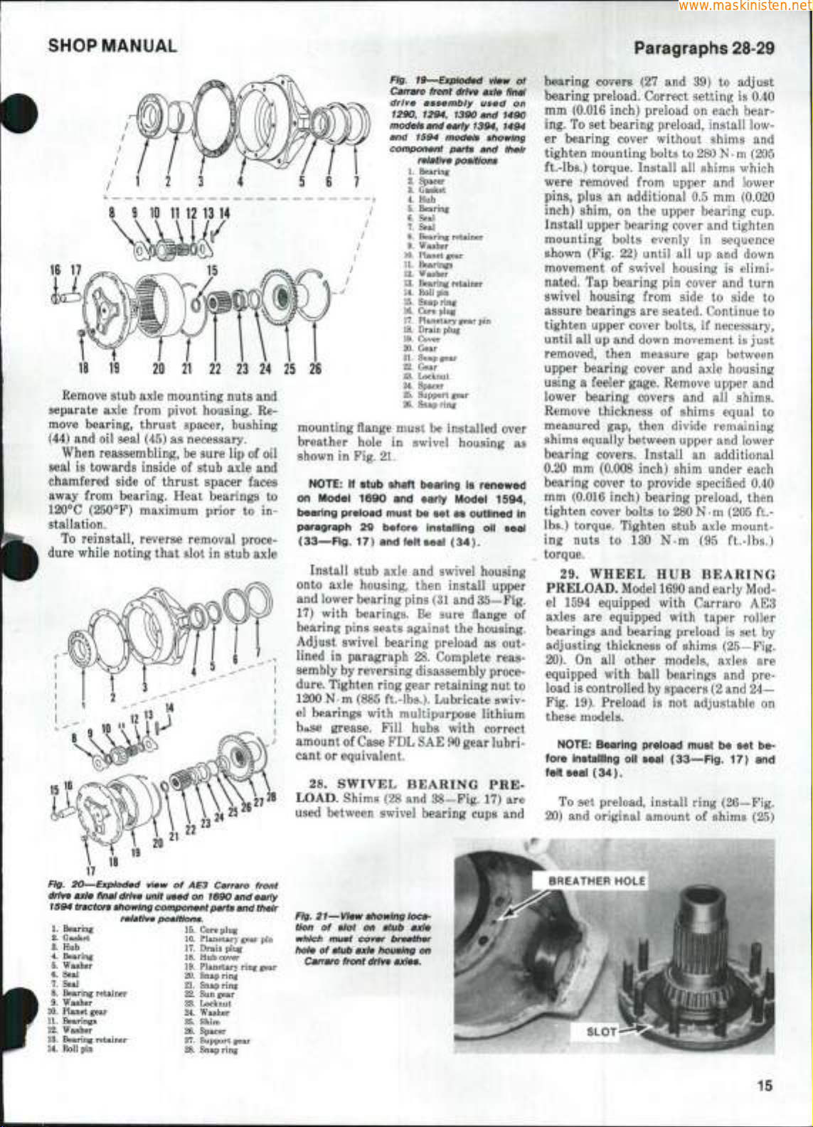
Fig. 19—Expioded view
Carraro front drive axie finai
drive assembiy used
1290, 1294, 1390 and 1490
modeis and eariy 1394,
and
1594
component parts
modeis showing
reiative positions
1.
Bearing
2.
Spacer
3.
Gasket
4.
Hub
5.
Bearing
6.
Seal
7.
Seal
8.
Bearing retainer
9.
Washer
10.
Planet gear
11.
Bearings
12.
Washer
13.
Bearing retainer
14.
Roll pin
15.
Snap ring
16.
Core plug
17.
Planetary gear pin
18.
Drain plug
19.
Cover
20.
Gear
21.
Snap gear
22.
Gear
23.
Locknut
24.
Spacer
25.
Support gear
26.
Snap ring
and
of
on
1494
their
mounting flange must be installed over
breather hole
shown
in
NOTE:
on Model 1690 and eariy Model 1594,
bearing preioad must be set as outlined In
paragraph 29 before instaiiing oil seal
(33-—Fig.
Install stub axle
in
swivel housing
as
Fig. 21.
If stub shaft bearing is renewed
17) and felt seal (34).
and
swivel housing
onto axle housing, then install upper
and lower bearing pins
17) with bearings.
(31
Be
sure flange
and 35—Fig.
of
bearing pins seats against the housing.
Adjust swivel bearing preload
lined
in
paragraph 28. Complete reas-
as out-
sembly by reversing disassembly procedure.
Tighten ring gear retaining nut
to
1200 N.m (885 ft.-lbs.). Lubricate swiv-
el bearings with multipurpose lithium
bttse grease. Fill hubs with correct
amount of Case FDL SAE 90 gear lubricant
or
equivalent.
28.
SWIVEL BEARING
LOAD. Shims (28
used between swivel bearing cups
and
38-Fig. 17)
PRE-
are
and
bearing covers
bearing preload. Correct setting
mm (0.016 inch) preload
ing. To
set
er bearing cover without shims
tighten mounting bolts
ft.-lbs.) torque. Install
were removed from upper
pins,
plus
inch) shim,
(27 and 39) to
on
each bear-
adjust
is
0.40
bearing preload, install low-
and
to
280 N-m (205
all
shims which
and
an
additional
on the
0.5 mm
upper bearing
lower
(0.020
cup.
Install upper bearing cover and tighten
mounting bolts evenly
shown (Fig.
movement
nated.
Tap
22)
until
of
swivel housing
bearing
swivel housing from side
assure bearings are seated. Continue
tighten upper cover bolts,
until
all up
and down movement is just
removed, then measure
upper bearing cover
using a feeler gage. Remove upper
lower bearing covers
Remove thickness
measured
gap,
then divide remaining
in
all up and
pin
cover
if
gap
and
axle housing
and all
of
shims equal
sequence
down
is
elimi-
and
to
turn
side
necessary,
between
shims.
to
to
and
to
shims equally between upper and lower
bearing covers. Install
0.20
mm
bearing cover
(0.008 inch) shim under each
to
an
additional
provide specified
0.40
mm (0.016 inch) bearing preload, then
tighten cover bolts
to
280
Nm
(205
ft.lbs.) torque. Tighten stub axle mounting nuts
to 130 N.m (95
ft.-lbs.)
torque.
29.
WHEEL
HUB
BEARING
PRELOAD. Model 1690 and early Mod-
el
1594
axles
are
bearings
adjusting thickness
20).
equipped with taper roller
and
bearing preload
of
On all
other models, axles
shims (25—Fig.
equipped with ball bearings
load is controlled by spacers (2 and
Fig.
19).
equipped with Carraro
Preload
is not
adjustable
AE3
is set by
are
and pre-
24—
on
these models.
NOTE:
fore instaiiing oil seai (33—Fig. 17) and
felt seal (34).
20)
Bearing preload must be set be-
To
set
preload, install ring (26—Fig.
and
original amount
of
shims
(25)
Fig, 20—exploded view
drive axie final drive unit used on 1690 and eariy
1594 tracton showing component parts and
1.
Bearing 15. Core plug
2.
Gasket
16.
3.
Hub 17.
4.
Bearing 18. Hub cover
5.
Washer
19.
6.
Seal
20.
7.
Seal 21. Snap ring
8.
Bearing retainer
9.
Washer 23. Locknut
10.
Planet gear
11.
Bearings 25. Shim
12.
Washer
13.
Bearing retainer
14.
Roll pin
. 24.
26,
28.
of AE3
reiative positions.
22.
27.
Carraro front
their
Planetary gear pin
Drain plug
Planetary ring gear
Snap ring
Sun gear
Washer
Spacer
Support gear
Snap ring
Fig. 21—View showing iocatlon
of
siot
on
which must cover breather
hoie
of
stub axie housing
Carraro front drive axies.
stub axie
on
15
Paragraphs 30-33
www.maskinisten.net
removed during disassembly. Install
washer
(24) and
cial socket (CAS-1645)
nut
to 1200 N-m (885
Install special fixture
23
on
wheel
wrench
to
needed
to
Correct bearing preload requires
N-m
(20
Add
or
subtract from shim thickness
(25—Fig.
obtained.
After preload
remove ring gear assembly
oil seal
and
ring gear with correct amount
and tighten locknut
ft.-lbs.) torque.
30.
PLANETARY GEARS. Drain
oil from
hub,
gear carrier (19—Fig.
20).
Mark location
pins and gears
be reassembled
tions.
Remove roll pins (14), then drive
planetary gear pins outward from gear
carrier.
Cup
Fig.
20)
will
Remove gears, thrust washers, spacers
and bearing rollers. Keep these parts
with their respective gear pins.
locknut (23).
to
tighten lock-
ft.-lbs.) torque.
as
shown
hub,
then
use a
measure amount
turn wheel
in.-lbs.) torque
20)
felt seal
hub.
to
until correct preload
is
correctly adjusted,
in hub.
to 1200 N-m (885
then remove planetary
19 or
of
in
planetary gear
the carrier so they can
in
their original posi-
plugs (16—Fig.
be
driven
out
Use spe-
in Fig.
torque
of
torque
2.3
turn
hub.
is
and
install
Reinstall
of
shims
18—Fig.
19 or
15—
with pins.
CASE INTERNATIONAL (DAVID BROWN)
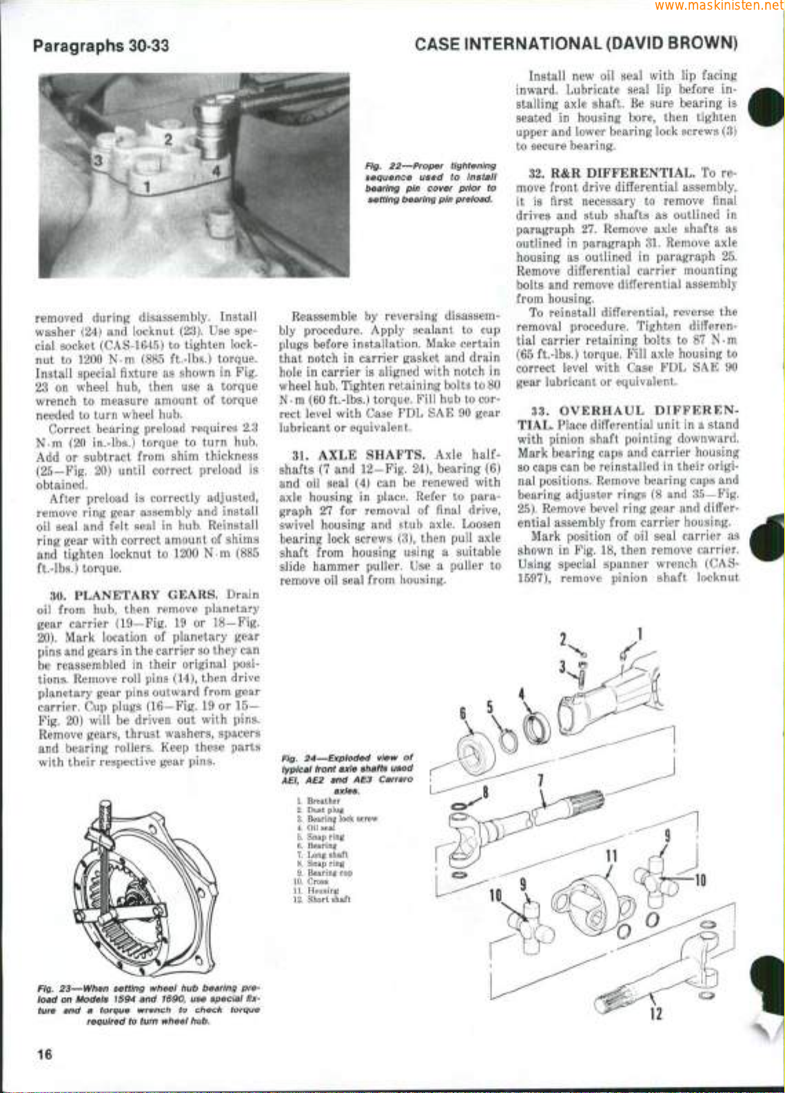
Fig. 22—Proper tightening
sequence used
bearing
setting bearing pin preioad.
Reassemble
by
reversing disassembly procedure. Apply sealant
plugs before installation. Make certain
that notch
hole
in
in
carrier
carrier gasket
is
aligned with notch
wheel hub. Tighten retaining bolts to 80
N-m (60 ft.-lbs.) torque. Fill hub
rect level with Case
lubricant
shafts
and
or
equivalent.
31.
AXLE SHAFTS. Axle
(7 and
oil
seal
(4) can be
axle housing
graph
27 for
swivel housing
bearing lock screws
FDL SAE 90
12-Fig.
in
place. Refer
removal
and
stub axle. Loosen
(3),
shaft from housing using a suitable
slide hammer puller.
remove
oil
seal from housing.
Fig. 24—Expioded view
typical
front
AEI,
10.
11.
12.
axle shafts used
AE2 and AE3
axles.
1.
Breather
2.
Dust plug
3.
Bearing lock screw
4.
Oil
seat
5.
Snap ring
6. Bearing
7.
Long shaft
8. Snap ring
9. Bearing cup
Cross
Housing
Short shaft
of
Carraro
to
pin
cover prior
to cup
and
24),
bearing
renewed with
to
of
final drive,
then pull axle
Use a
puller
instaii
to
drain
in
to
cor-
gear
half-
(6)
para-
to
Install
new oil
inward. Lubricate seal
stalling axle shaft.
seated
in
housing bore, then tighten
upper
and
lower bearing lock screws
seal with
lip
Be
sure bearing
lip
facing
before
in-
is
(3)
to secure bearing.
32.
R&R
DIFFERENTIAL.
To remove front drive differential assembly,
it
is
first necessary
drives
and
paragraph
outlined
housing
in
as
stub shafts
27.
paragraph 31. Remove axle
outlined
to
remove final
as
outlined
Remove axle shafts
in
paragraph
in
as
25.
Remove differential carrier mounting
bolts
and
remove differential assembly
from housing.
To reinstall differential, reverse
the
removal procedure. Tighten differential carrier retaining bolts
(65 ft.-lbs.) torque. Fill axle housing
correct level with Case
gear lubricant
33.
OVERHAUL DIFFEREN-
or
equivalent.
TIAL. Place differential unit
to 87 N-m
to
FDL SAE 90
in a
stand
with pinion shaft pointing downward.
Mark bearing caps
so caps can be reinstalled
nal positions. Remove bearing caps
bearing adjuster rings
25).
Remove bevel ring gear
and
carrier housing
in
their origi-
(8 and
and
and
35—Fig.
differ-
ential assembly from carrier housing.
Mark position
shown
in Fig. 18,
Using special spanner wrench
1597),
remove pinion shaft locknut
of oil
seal carrier
then remove carrier.
(CAS-
as
Fig. 23—When setting wheel
ioad
on
Modeis 1594
ture
and a
torque wrench
required
16
to
and
turn
hub
1690,
use
to
check torque
wheei hub.
bearing
speciai
pre-
fix-
SHOP MANUAL
www.maskinisten.net
Paragraphs 34-35
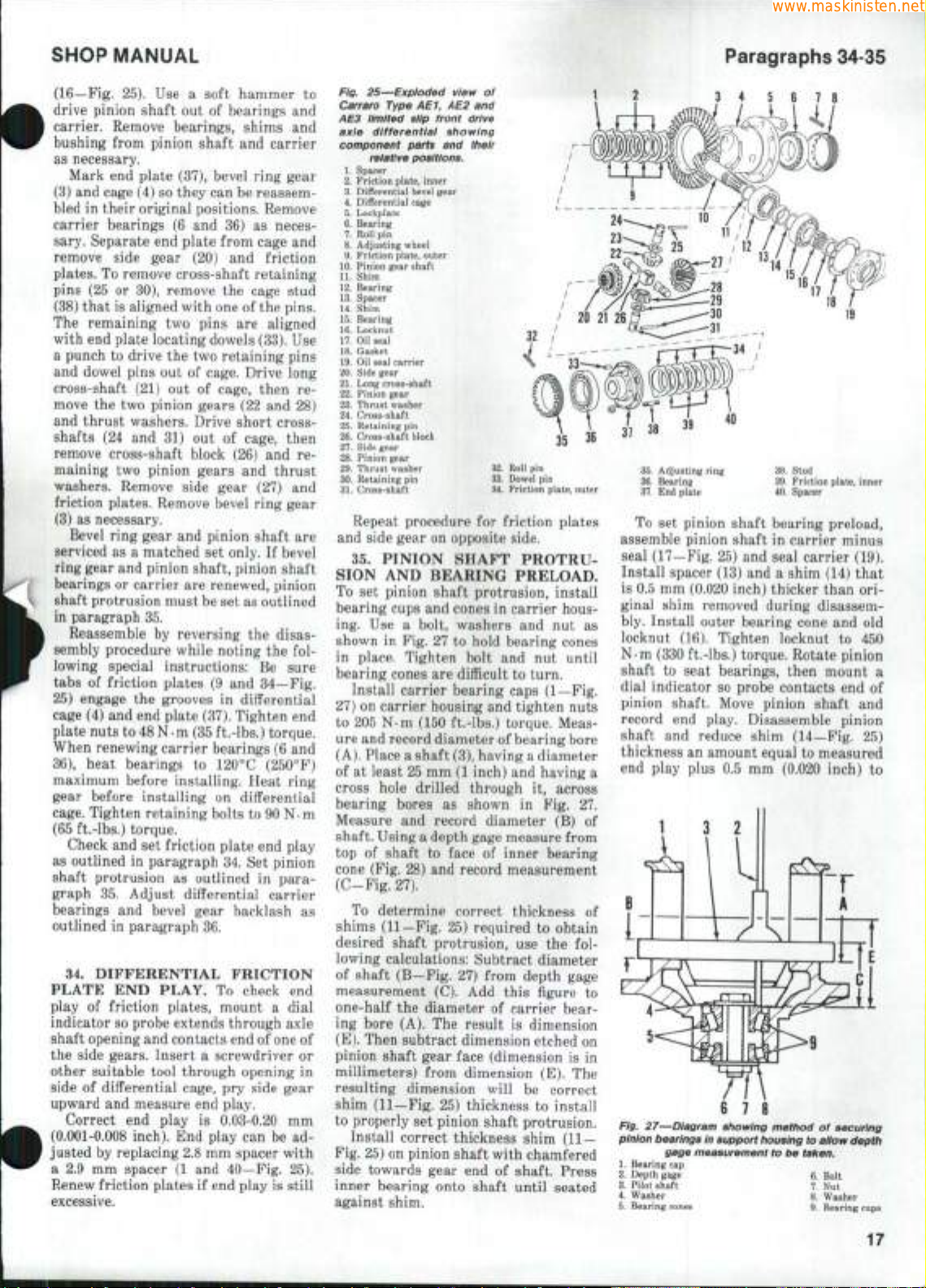
(16—Fig. 25). Use a soft hammer to
drive pinion shaft out of bearings and
carrier. Remove bearings, shims and
bushing from pinion shaft and carrier
as necessary.
Mark end plate (37), bevel ring gear
(3) and cage (4) so they can be reassembled in their original positions. Remove
carrier bearings (6 and 36) as neces-
sary. Separate end plate from cage and
remove side gear (20) and friction
plates.
To remove cross-shaft retaining
pins (25 or 30), remove the cage stud
(38) that is aligned with one of the pins.
The remaining two pins are aligned
with end plate locating dowels (33). Use
a punch to drive the two retaining pins
and dowel pins out of cage. Drive long
cross-shaft (21) out of cage, then re-
move the two pinion gears (22 and 28)
and thrust washers. Drive short crossshafts (24 and 31) out of cage, then
remove cross-shaft block (26) and remaining two pinion gears and thrust
washers. Remove side gear (27) and
friction plates. Remove bevel ring gear
(3) as necessary.
Bevel ring gear and pinion shaft are
serviced as a matched set only. If bevel
ring gear and pinion shaft, pinion shaft
bearings or carrier are renewed, pinion
shaft protrusion must be set as outlined
in paragraph 35.
Reassemble by reversing the disassembly procedure while noting the foliowing special instructions: Be sure
tabs of friction plates (9 and 34—Fig.
25) engage the grooves in differential
cage (4) and end plate (37). Tighten end
plate nuts to
48 N • m
(35 ft-lbs.) torque.
When renewing carrier bearings (6 and
36),
heat bearings to 120°C (250°F)
maximum before installing. Heat ring
gear before installing on differential
cage.
Tighten retaining bolts to 90 N-m
(65 ft.-lbs.) torque.
Check and set friction plate end play
as outlined in paragraph 34. Set pinion
shaft protrusion as outlined in para-
graph 35. Adjust differential carrier
bearings and bevel gear backlash as
outlined in paragraph 36.
34.
DIFFERENTIAL FRICTION
PLATE END PLAY. To check end
play of friction plates, mount a dial
indicator so probe extends through axle
shaft opening and contacts end of one of
the side gears. Insert a screwdriver or
other suitable tool through opening in
side of differential cage, pry side gear
upward and measure end play.
Correct end play is 0.03-0.20 mm
(0.001-0.008 inch). End play can be adjusted by replacing 2.8 mm spacer with
a 2.9 mm spacer (1 and 40—Fig. 25).
Renew friction plates if end play is still
excessive.
Fig. 25—Exploded view of
Carraro Type AE1, AE2 and
AE3 limited siip front drive
axle differential showing
component parts and their
relative positions.
1.
Spacer
2.
Friction
plate,
pin
plate,
pin
pin
inner
outer
32.
Roll
33.
Dowei
34.
Friction
pin
pin
plate,
outer
3.
Differential bevel gear
4.
Differential cage
5.
Lockplate
6.
Bearing
7.
Roll
8.
Adjusting wheel
9.
Friction
10.
Pinion gear shaft
11.
Shim
12.
Bearing
13.
Spacer
14.
Shim
15.
Bearing
16.
Locknut
17.
Oil
seal
18.
Gasket
19.
Oil
seal carrier
20.
Side gear
21.
Long cross-shaft
22.
Pinion gear
23.
Thrust washer
24.
Cross-shaft
25.
Retaining
26.
Cross-shaft block
27.
Side gear
28.
Pinion gear
29.
Thrust washer
30.
Retaining
31.
Cross-shaft
Repeat procedure for friction plates
and side gear on opposite side.
35.
PINION SHAFT PROTRU-
SION AND BEARING PRELOAD.
To set pinion shaft protrusion, install
bearing cups and cones in carrier housing. Use a bolt, washers and nut as
shown in Fig. 27 to hold bearing cones
in place. Tighten bolt and nut until
bearing cones are difficult to turn.
Install carrier bearing caps (1—Fig.
27) on carrier housing and tighten nuts
to 205 N-m (150 ft.-lbs.) torque. Measure and record diameter of bearing bore
(A).
Place a shaft (3), having a diameter
of at least 25 mm (1 inch) and having a
cross hole drilled through it, across
bearing bores as shown in Fig. 27.
Measure and record diameter (B) of
shaft. Using a depth gage measure from
top of shaft to face of inner bearing
cone (Fig. 28) and record measurement
(C-Fig. 27).
To determine correct thickness of
shims (11—Fig. 25) required to obtain
desired shaft protrusion, use the following calculations: Subtract diameter
of shaft (B—Fig. 27) from depth gage
measurement (C). Add this figure to
one-half the diameter of carrier bearing bore (A). The result is dimension
(E).
Then subtract dimension etched on
pinion shaft gear face (dimension is in
millimeters) from dimension (E). The
resulting dimension will be correct
shim (11—Fig. 25) thickness to install
to properly set pinion shaft protrusion.
Install correct thickness shim
(11 —
Fig. 25) on pinion shaft with chamfered
side towards gear end of shaft. Press
inner bearing onto shaft until seated
against shim.
35.
Adjusting ring
36.
Bearing
37.
End
plate
38.
39.
40.
Spacer
Stud
Friction
plate,
inner
To set pinion shaft bearing preload,
assemble pinion shaft in carrier minus
seal (17—Fig. 25) and seal carrier (19).
Install spacer (13) and a shim (14) that
is 0.5 mm (0.020 inch) thicker than ori-
ginal shim removed during disassem-
bly. Install outer bearing cone and old
locknut (16). Tighten locknut to 450
N-m (330 ft.-lbs.) torque. Rotate pinion
shaft to seat bearings, then mount a
dial indicator so probe contacts end of
pinion shaft. Move pinion shaft and
record end play. Disassemble pinion
shaft and reduce shim (14—Fig. 25)
thickness an amount equal to measured
end play plus 0.5 mm (0.020 inch) to
r
6
Fig. 27—Diagram showing method of securing
pinion bearings in support
gage measurement to be taken.
1.
Bearing
cap
2.
Depth gage
3.
Pilot shaft
4.
Washer
5.
Bearing cones
7. Nut
8.
7 8
housing
6.
9.
to allow depth
Bolt
Washer
Bearing cups
17
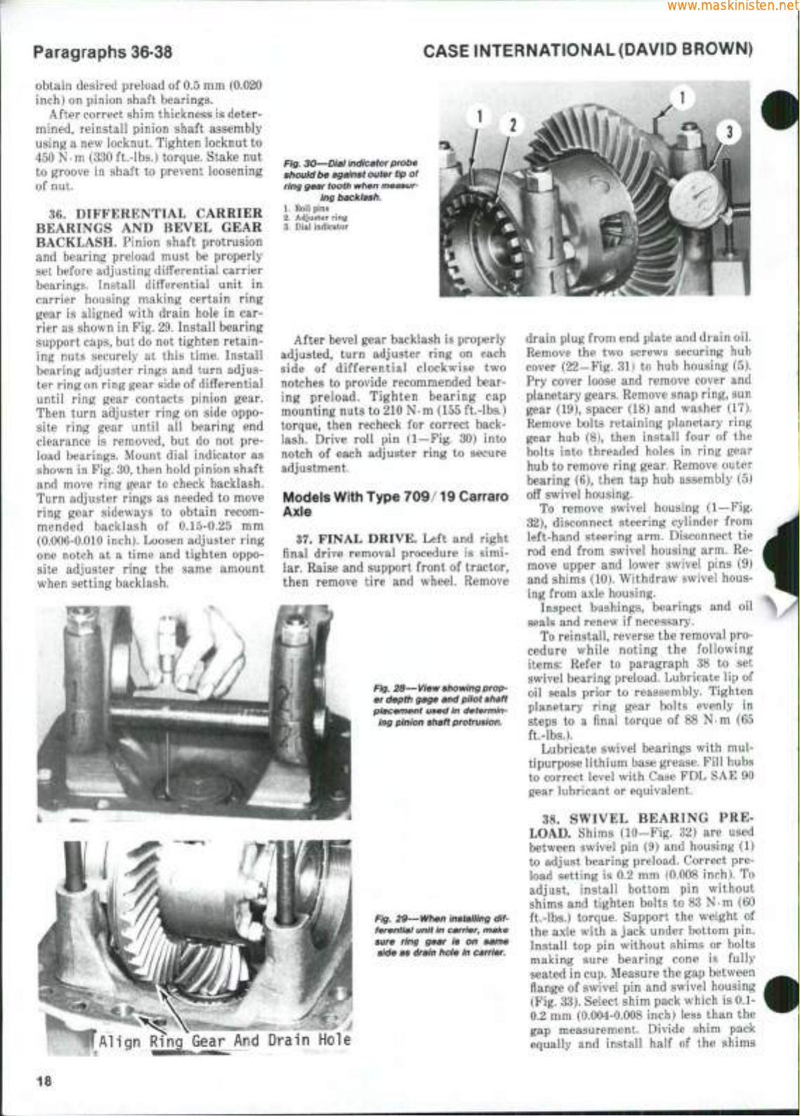
Paragraphs 36-38
www.maskinisten.net
obtain desired preload of 0.5 mm (0.020
inch) on pinion shaft bearings.
After correct shim thickness is determined, reinstall pinion shaft assembly
using a new locknut. Tighten locknut to
450 N.m (330 ft.-lbs.) torque. Stake nut
to groove in shaft to prevent loosening
of nut.
36.
DIFFERENTIAL CARRIER
BEARINGS AND BEVEL GEAR
BACKLASH. Pinion shaft protrusion
and bearing preload must be properly
set before adjusting differential carrier
bearings. Install differential unit in
carrier housing making certain ring
gear is aligned with drain hole in carrier as shown in Fig. 29. Install bearing
support caps, but do not tighten retaining nuts securely at this time. Install
bearing adjuster rings and turn adjuster ring on ring gear side of differential
until ring gear contacts pinion gear.
Then turn adjuster ring on side oppo-
site ring gear until all bearing end
clearance is removed, but do not preload bearings. Mount dial indicator as
shown in Fig. 30, then hold pinion shaft
and move ring gear to check backlash.
Turn adjuster rings as needed to move
ring gear sideways to obtain recommended backlash of 0.15-0.25 mm
(0.006-0.010 inch). Loosen adjuster ring
one notch at a time and tighten opposite adjuster ring the same amount
when setting backlash.
CASE INTERNATIONAL (DAVID BROWN)
Fig. 30—Diai indicator probe
shouid
be against outer tip of
ring gear tooth when measur-
ing backiash.
1.
Roll pins
2.
Adjuster ring
3.
Dial indicator
After bevel gear backlash is properly
adjusted, turn adjuster ring on each
side of differential clockwise two
notches to provide recommended bearing preload. Tighten bearing cap
mounting nuts to 210 N-m (155 ft.-lbs.)
torque, then recheck for correct backlash. Drive roll pin (1—Fig. 30) into
notch of each adjuster ring to secure
adjustment.
Models With Type 709/19 Carraro
Axle
37.
FINAL DRIVE. Left and right
final drive removal procedure is similar. Raise and support front of tractor,
then remove tire and wheel. Remove
Fig. 26—View
er depth gage and piiot shaft
piacement used in determin-
ing pinion shaft
showing
protrusion.
prop-
drain plug from end plate and drain oil.
Remove the two screws securing hub
cover (22—Fig. 31) to hub housing (5).
Pry cover loose and remove cover and
planetary gears. Remove snap ring, sun
gear (19), spacer (18) and washer (17).
Remove bolts retaining planetary ring
gear hub (8), then install four of the
bolts into threaded holes in ring gear
hub to remove ring gear. Remove outer
bearing (6), then tap hub assembly (5)
off swivel housing.
To remove swivel housing (1—Fig.
32),
disconnect steering cylinder from
left-hand steering arm. Disconnect tie
rod end from swivel housing arm. Re-
move upper and lower swivel pins (9)
and shims (10). Withdraw swivel housing from axle housing.
Inspect bushings, bearings and oil
seals and renew if necessary.
To reinstall, reverse the removal procedure while noting the following
items:
Refer to paragraph 38 to set
swivel bearing preload. Lubricate lip of
oil seals prior to reassembly. Tighten
planetary ring gear bolts evenly in
steps to a final torque of 88 N-m (65
ft.-lbs.).
Lubricate swivel bearings with multipurpose lithium base grease. Fill hubs
to correct level with Case FDL SAE 90
gear lubricant or equivalent.
18
Fig. 29—When instaiiing differentiai unit in
sure ring gear is on same
side as drain hoie in
carrier,
maiie
carrier.
38.
SWIVEL BEARING PRE-
LOAD. Shims (10-Fig. 32) are used
between swivel pin (9) and housing (1)
to adjust bearing preload. Correct pre-
load setting is 0.2 mm (0.008 inch). To
adjust, install bottom pin without
shims and tighten bolts to 83 N m (60
ft.-lbs.) torque. Support the weight of
the axle with a jack under bottom pin.
Install top pin without shims or bolts
making sure bearing cone is fully
seated in cup. Measure the gap between
flange of swivel pin and swivel housing
(Fig. 33). Select shim pack which is 0.1-
0.2 mm (0.004-0.008 inch) less than the
gap measurement. Divide shim pack
equally and install half of the shims
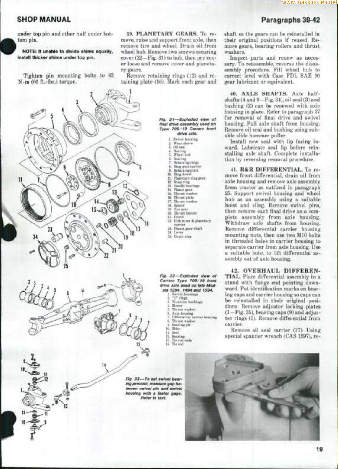
SHOP MANUAL
www.maskinisten.net
Paragraphs 39-42
under top pin and other half under bottom pin.
NOTE:
If unable to divide shims equally,
install thicker shims under top pin.
Tighten pin mounting bolts to
83
N-m (60 ft.-lbs.) torque.
2
39.
PLANETARY GEARS. To re-
move, raise and support front axle, then
remove tire and wheel. Drain oil from
wheel hub. Remove two screws securing
cover (22—Fig. 31) to hub, then pry cover loose and remove cover and planetary gears.
Remove retaining rings (12) and re-
taining plate (16). Mark each gear and
Fig. 31—Exploded view of
final drive assembly used on
Type 709/19 Carraro front
drive axle.
1.
Swivel housing
2.
Wear sleeve
3.
Oil seal
4.
Bearing
5.
Wheel hub
6.
Bearing
7.
Retaining rings
8.
Ring gear carrier
9.
Retaining plate
10.
Ring dowel
11.
Planetary ring gear.
12.
Snap ring
13.
Needle bearings
14.
Planet gear
15.
Thrust washer
16.
Thrust plate
17.
Thrust washer
18.
Spacer
19.
Sun gear
20.
Thrust button
21.
Dowel
ffi.
Hub
cover & planetary
carrier
23.
Planet gear sh^t
24.
Cover
25.
Drain plug
shaft
SO
the gears can be reinstalled in
their original positions if reused. Remove gears, bearing rollers and thrust
washers.
Inspect parts and renew as necessary. To reassemble, reverse the disassembly procedure. Fill wheel hub to
correct level with Case FDL SAE 90
gear lubricant or equivalent.
40.
AXLE SHAFTS. Axle
halfshafts (4 and 9—Fig. 34), oil seal (3) and
bushing (2) can be renewed with axle
housing in place. Refer to paragraph 37
for removal of final drive and swivel
housing. Pull axle shaft from housing.
Remove oil seal and bushing using suitable slide hammer puller.
Install new seal with lip facing in-
ward. Lubricate seal lip before rein-
stalling axle shaft. Complete installation by reversing removal procedure.
41.
R&R DIFFERENTIAL. To re-
move front differential, drain oil from
axle housing and remove axle assembly
from tractor as outlined in paragraph
25.
Support swivel housing and wheel
hub as an assembly using a suitable
hoist and sling. Remove swivel pins,
then remove each final drive as a complete assembly from axle housing.
Withdraw axle shafts from housing.
Remove differential carrier housing
mounting nuts, then use two MIO bolts
in threaded holes in carrier housing to
separate carrier from axle housing. Use
a suitable hoist to lift differential assembly out of axle housing.
Fig. 32—Exploded view of
Carraro Type 709/19 front
drive axle used on late Mod-
els 1394, 1494 and 1594.
1.
Swivel housings
2.
"0" rings
3.
Trunnion bushings
4.
Sleeve
5.
Thrust washer
6.
Axle housing
7.
Differential carrier housing
8.
Thrust washer
9.
Bearing pin
10.
Shim
11.
Seal
12.
Bearing
13.
Tie rod ends
14.
Tie rod
Flg. 33—To set swivei
ing preload, measure gap between swivel pin and swivel
housing with a feeier gage.
Refer to
bear-
text.
42.
OVERHAUL
DIFFEREN-
TIAL. Place differential assembly in a
stand with flange end pointing downward. Put identification marks on bearing caps and carrier housing so caps can
be reinstalled in their original positions.
Remove adjuster locking plates
(1—Fig. 35), bearing caps (9) and adjuster rings (3). Remove differential from
carrier.
Remove oil seal carrier (17). Using
special spanner wrench (CAS 1597), re-
19

Paragraphs 43-44
www.maskinisten.net
CASE INTERNATIONAL (DAVID BROWN)
move pinion shaft locknut (15), then
drive pinion shaft (7) out of carrier.
Remove bearings (11), spacer (12) and
shims (10 and 13) as necessary.
Remove carrier bearings (4) using a
suitable puller. Remove bevel ring gear
mounting bolts that are aligned with
pinion gear shaft (24), then turn housing so retaining pin (25) falls out
through ring gear bolt hole. Remove
remaining ring gear mounting bolts
and remove gear from housing if necessary. Push pinion shaft out of housing,
then withdraw pinion gears (22), side
gears (21) and friction plates from
housing. Remove axle shaft bushings
from differential case as necessary.
Bevel ring gear (6) and pinion shaft
(7) are serviced as a matched set only
and must be installed as such. If bevel
ring gear and pinion shaft, pinion shaft
bearings or carrier housing are re-
Fig. 34—Exploded view of
typlcai axie shafts used on
Carraro 709/19 axie.
1.
Axle housing
2.
Bushing
3.
Oil seal
4.
Long shaft
5.
Retaining ring
6. Bearing cap
7. Cross
8. Housing
9. Short shaft
newed, pinion shaft protrusion must be
set as outlined in paragraph 44.
Reassemble by reversing the disassembly procedure while noting the following special instructions: Install
backing plate (20) on side gears first,
then alternately assemble friction
plates beginning and ending with a
plate with tabs (19). Align pin hole in
pinion shaft (24) with hole in case, then
install retaining pin (25). Apply Loctite
270 to threads of ring gear mounting
bolts,
then tighten to 70 N-m (52 ft.-
lbs.) torque.
Check friction plate end play as outlined in paragraph 43. Adjust pinion
shaft protrusion and bearing preload as
outlined in paragraph 44. Reinstall differential in carrier housing making
sure ring gear is aligned with housing
drain plug (Fig. 36). Adjust bevel gear
backlash and carrier bearing preload as
outlined in paragraph 45.
4a. DIFFERENTIAL FRICTION
PLATE END PLAY. To check friction
plate end play, place differential assembly in a vertical position. Mount a
dial indicator so probe extends through
axle shaft opening and contacts the end
of one of the side gears. Insert a screwdriver or other suitable tool through
opening in side of differential cage, pry
side gear upward and measure end
play.
Correct end play is 0.03-0.20 mm
(0.001-0.008 inch). End play can be ad-
justed by replacing 2.8 mm thick spacer
(20—Fig. 35) with a 2.9 mm thick spacer
plate. Renew friction plates if end play
is still not within specified tolerance.
Repeat procedure for plates on opposite side.
Fig. 35—Exploded view of Carraro Type 709/19 front drive axle iimited siip differentiai assembiy.
1.
Adjuster locking plates
2.
Bushing 10. Shim 18, Friction plates, splined
3.
Adjuster rings 11. Bearings 19. Friction plates with tabs
4.
Carrier bearings 12. Spacer 20. Backing plate
5.
Differential case 13. Shim 21. Side gear
6. Bevel ring gear 14. Washer 22. Pinion gear
7.
Bevel pinion gear 15. Locknut 23. Thrust washer
8. Differential carrier housing 16. Oil seal 24. Pinion shaft
9. Bearing cap 17. Seal carrier 25. Retaining pin
20
44.
PINION SHAFT PROTRU-
SION AND BEARING PRELOAD.
To set pinion shaft protrusion, install
bearing cups in carrier housing. Install
carrier bearing caps (9—Fig. 35) and
tighten nuts to 198 N-m (145 ft.-lbs.)
torque. Install bearing cones in carrier
using a bolt, flat washers and nut (Fig.
38) to hold bearings in place. Tighten
nut and bolt until bearing cones are difficult to turn.
Measure and record diameter of car-
rier bearing cap bore (A—Fig. 38).
Place a si ift (3), having a diameter of
at least 2J mm (1 inch) and having a
cross hole drilled through it, across
bearing bores as shown. Measure and
record diameter (B) of shaft. Insert a
depth gage through hole in shaft and
measure distance (C) from top of shaft
to face of inner bearing cone.
To determine correct thickness of
shims (10—Fig. 35) required to provide
desired pinion shaft protrusion, use the
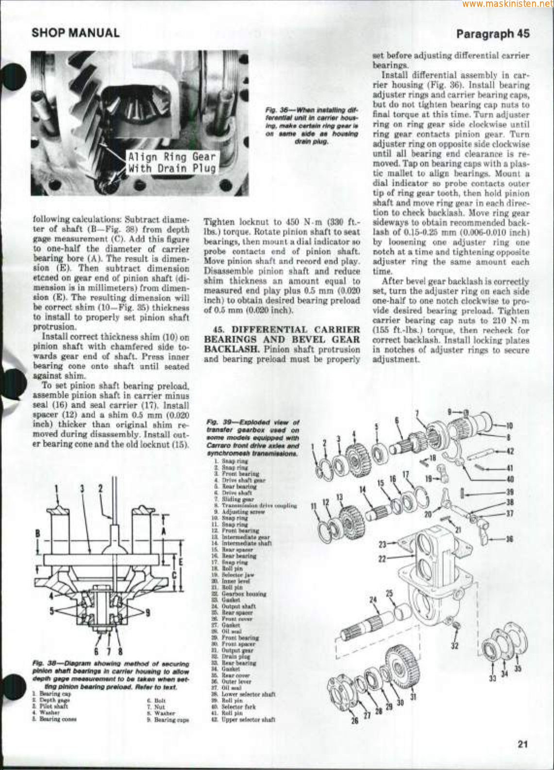
SHOP MANUAL
www.maskinisten.net
ign Ring
With Drain
following calculations: Subtract diameter of shaft (B—Fig. 38) from depth
gage measurement (C). Add this figure
to one-half the diameter of carrier
bearing bore (A). The result is dimension (E). Then subtract dimension
etcned on gear end of pinion shaft (dimension is in millimeters) from dimension (E). The resulting dimension will
be correct shim (10—Fig. 35) thickness
to install to properly set pinion shaft
protrusion.
Install correct thickness shim (10) on
pinion shaft with chamfered side towards gear end of shaft. Press inner
bearing cone onto shaft until seated
against shim.
To set pinion shaft bearing preload,
assemble pinion shaft in carrier minus
seal (16) and seal carrier (17). Install
spacer (12) and a shim 0.5 mm (0.020
inch) thicker than original shim removed during disassembly. Install out-
er bearing cone and the old locknut (15).
3
2
Fig. 38—Diagram showing method of securing
pinion shaft bearings in carrier housing to allow
depth gage measurement to be taken when set-
ting pinion bearing preioad. Refer to
1.
Bearing cap
2.
Depth gage 6. Bolt
3.
Pilot shaft 7. Nut
4.
Washer 8. Washer
5.
Bearing cones 9. Bearing cups
text.
Fig. 36—When Instaiiing differentiai unit In carrier housing, maite certain ring gear Is
on same side as housing
drain piug.
Tighten locknut to 450 N-m (330 ft.lbs.) torque. Rotate pinion shaft to seat
bearings, then mount a dial indicator so
probe contacts end of pinion shaft.
Move pinion shaft and record end play.
Disassemble pinion shaft and reduce
shim thickness an amount equal to
measured end play plus 0.5 mm (0.020
inch) to obtain desired bearing preload
of 0.5 mm (0.020 inch).
45.
DIFFERENTIAL CARRIER
BEARINGS AND BEVEL GEAR
BACKLASH. Pinion shaft protrusion
and bearing preload must be properly
Fig. 39—Exploded view of
transfer gearbox used on
some models equipped with
Carraro front drive axles and
synchromesh
1.
Snap ring
2.
Snap ring
3.
Front bearing
4.
Drive shaft gear
5.
Rear bearing
6. Drive shaft
7.
Sliding gear
8. Transmission drive coupling
9. Adjusting screw
10.
Snap ring
11.
Snap ring
12.
Front bearing
13.
Intermediate gear
14.
Intermediate shaft
15.
Rear spacer
16.
Rear bearing
17.
Snap ring
18.
Roll pin
19.
Selector jaw
20. Inner level
21.
Roll pin
22.
Gearbox housing
23.
Gasket
24.
Output shaft
25.
Rear spacer
26.
Front cover
27.
Gasket
28.
Oil seal
29.
Front bearing
30.
Front spacer
31.
Output gear
32.
Drain plug
33.
Rear bearing
34.
Gasket
35.
Rear cover
36.
Outer lever
37.
Oil seal
38.
Lower selector shaft
39.
Roll pin
40.
Selector fork
41.
Roll pin
42.
Upper selector shaft
transmissions.
Paragraph 45
set before adjusting differential carrier
bearings.
Install differential assembly in carrier housing (Fig. 36). Install bearing
adjuster rings and carrier bearing caps,
but do not tighten bearing cap nuts to
final torque at this time. Turn adjuster
ring on ring gear side clockwise until
ring gear contacts pinion gear. Turn
adjuster ring on opposite side clockwise
until all bearing end clearance is removed. Tap on bearing caps with a plastic mallet to align bearings. Mount a
dial indicator so probe contacts outer
tip of ring gear tooth, then hold pinion
shaft and move ring gear in each direction to check backlash. Move ring gear
sideways to obtain recommended backlash of 0.15-0.25 mm (0.006-0.010 inch)
by loosening one adjuster ring one
notch at a time and tightening opposite
adjuster ring the same amount each
time.
After bevel gear backlash is correctly
set, turn the adjuster ring on each side
one-half to one notch clockwise to provide desired bearing preload. Tighten
carrier bearing cap nuts to 210 N-m
(155 ft.-lbs.) torque, then recheck for
correct backlash. Install locking plates
in notches of adjuster rings to secure
adjustment.
35
21
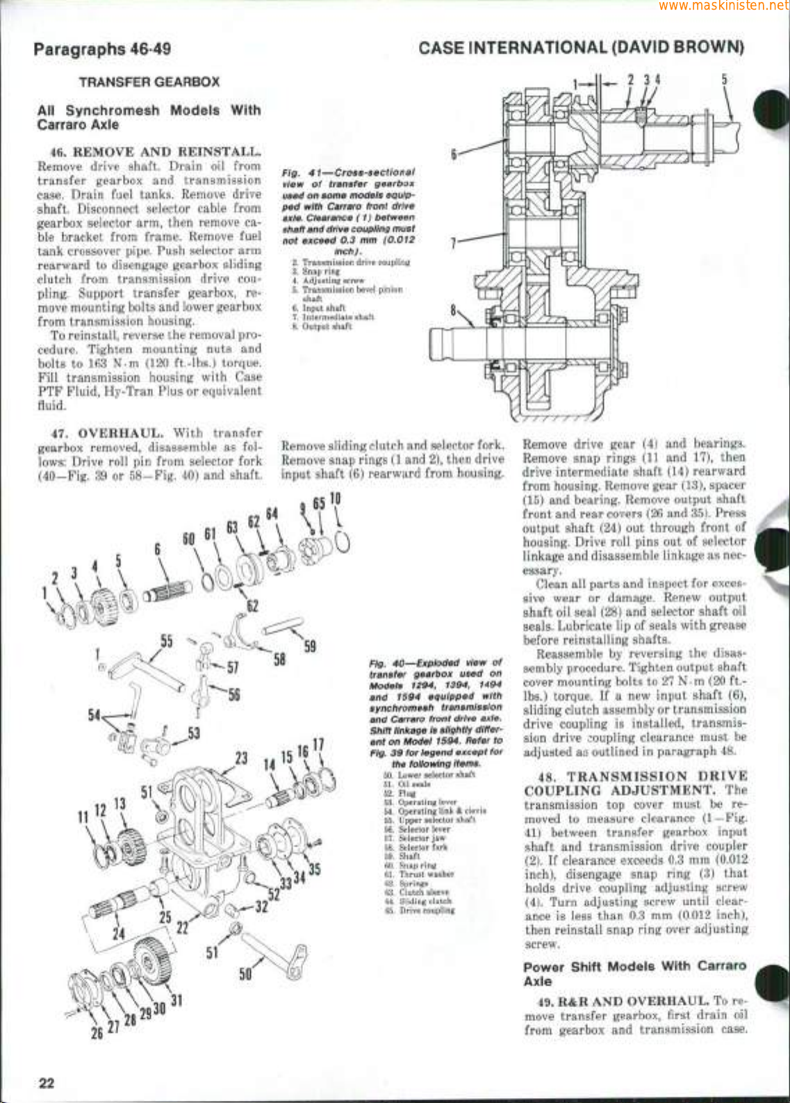
Paragraphs 46-49
www.maskinisten.net
TRANSFER GEARBOX
All Synchromesh Models With
Carraro Axle
46.
REMOVE AND REINSTALL.
Remove drive shaft. Drain oil from
transfer gearbox and transmission
case.
Drain fuel tanks. Remove drive
shaft. Disconnect selector cable from
gearbox selector arm, then remove ca-
ble bracket from frame. Remove fuel
tank crossover pipe. Push selector arm
rearward to disengage gearbox sliding
clutch from transmission drive coupling. Support transfer gearbox, remove mounting bolts and lower gearbox
from transmission housing.
To reinstall, reverse the removal procedure. Tighten mounting nuts and
bolts to 163 N-m (120 ft.-lbs.) torque.
Fill transmission housing with Case
PTF Fluid, Hy-Tran Plus or equivalent
fluid.
47.
OVERHAUL. With transfer
gearbox removed, disassemble as follows:
Drive roll pin from selector fork
(40—Fig. 39 or 58—Fig. 40) and shaft.
55
^Q
(Oi:^^^
^-57
58
CASE INTERNATIONAL (DAVID BROWN)
Fig. 41—Cross-sectionai
view of transfer gearbox
used on some modeis equipped with Carraro front drive
axie. Ciearance (1) between
shaft and
drive coupiing must
not exceed 0.3 mm (0.012
inch).
2.
Transmission drive coupling
3.
Snap ring
4.
Adjusting screw
5.
Transmission bevel pinion
shaft
6.
Input shaft
7.
Intermediate shaft
8.
Output shaft
Remove sliding clutch and selector fork.
Remove snap rings (1 and 2), then drive
input shaft (6) rearward from housing.
'59
Fig. 40—Expioded view of
transfer gearbox used on
Modeis 1294, 1394, 1494
and 1594 equipped with
synchromesh transmission
and Carraro front drive axie.
Shift iinkage is siightiy
ent on Modei 1594. Refer to
Fig. 39 for iegend except for
the foiiowing items.
50.
Lower selector shaft
51.
Oil
seals
52.
Plug
53.
Operating lever
54.
Operating link & clevis
55.
Upper selector shaft
56.
Selector lever
57.
Selector
58.
59.
60.
61.
62.
63.
64.
65.
jaw
Selector fork
Shaft
Snap ring
Thrust washer
Springs
Clutch sleeve
Sliding clutch
Drive coupling
differ-
Remove drive gear (4) and bearings.
Remove snap rings (11 and 17), then
drive intermediate shaft (14) rearward
from housing. Remove gear (13), spacer
(15) and bearing. Remove output shaft
front and rear covers (26 and 35). Press
output shaft (24) out through front of
housing. Drive roll pins out of selector
linkage and disassemble linkage as necessary.
Clean all parts and inspect for exces-
sive wear or damage. Renew output
shaft oil seal (28) and selector shaft oil
seals.
Lubricate lip of seals with grease
before reinstalling shafts.
Reassemble by reversing the disassembly procedure. Tighten output shaft
cover mounting bolts to 27 N-m (20 ft.lbs.) torque. If a new input shaft (6),
sliding clutch assembly or transmission
drive coupling is installed, transmission drive coupling clearance must be
adjusted as outlined in paragraph 48.
48.
TRANSMISSION DRIVE
COUPLING ADJUSTMENT. The
transmission top cover must be removed to measure clearance (1—Fig.
41) between transfer gearbox input
shaft and transmission drive coupler
(2).
If clearance exceeds 0.3 mm (0.012
inch),
disengage snap ring (3) that
holds drive coupling adjusting screw
(4).
Turn adjusting screw until clearance is less than 0.3 mm (0.012 inch),
then reinstall snap ring over adjusting
screw.
22
Power Shift Modeis With Carraro
Axle
49.
R&R AND OVERHAUL. To re-
move transfer gearbox, first drain oil
from gearbox and transmission case.
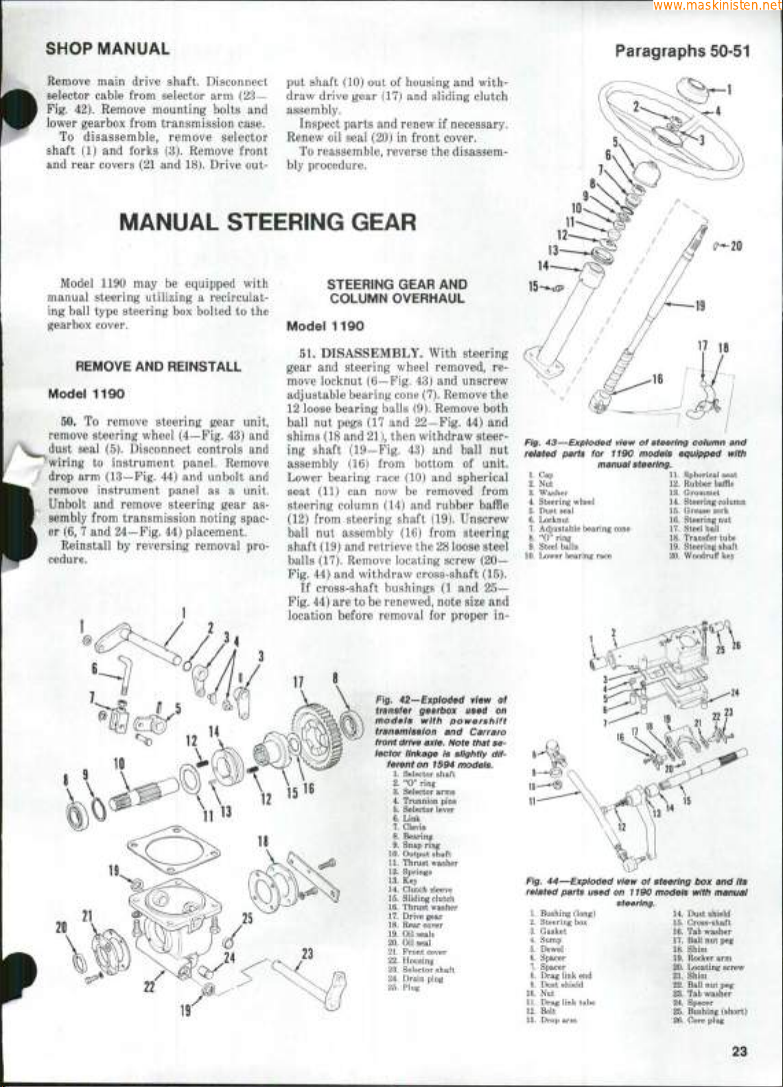
SHOP MANUAL
www.maskinisten.net
Paragraphs 50-51
Remove main drive shaft. Disconnect
selector cable from selector arm (23—
Fig. 42). Remove mounting bolts and
lower gearbox from transmission case.
To disassemble, remove selector
shaft (1) and forks (3). Remove front
and rear covers (21 and 18). Drive out-
MANUAL STEERING GEAR
Model 1190 may be equipped with
manual steering utilizing a recirculating ball type steering box bolted to the
gearbox cover.
REMOVE AND REINSTALL
Model 1190
50.
To remove steering gear unit,
remove steering wheel (4—Fig. 43) and
dust seal (5). Disconnect controls and
'wiring to instrument panel. Remove
drop arm (13—Fig. 44) and unbolt and
remove instrument panel as a unit.
Unbolt and remove steering gear assembly from transmission noting spac-
er (6, 7 and 24—Fig. 44) placement.
Reinstall by reversing removal pro-
cedure.
put shaft (10) out of housing and with-
draw drive gear (17) and sliding clutch
assembly.
Inspect parts and renew if necessary.
Renew oil seal (20) in front cover.
To reassemble, reverse the disassem-
bly procedure.
STEERING GEAR AND
COLUMN OVERHAUL
Model 1190
51.
DISASSEMBLY. With steering
gear and steering wheel removed, remove locknut (6—Fig. 43) and unscrew
adjustable bearing cone
(7).
Remove the
12 loose bearing balls (9). Remove both
ball nut pegs (17 and 22-Fig. 44) and
shims (18 and 21), then withdraw steering shaft (19—Fig. 43) and ball nut
assembly (16) from bottom of unit.
Lower bearing race (10) and spherical
seat (11) can now be removed from
steering column (14) and rubber baffle
(12) from steering shaft (19). Unscrew
ball nut assembly (16) from steering
shaft (19) and retrieve the 28 loose steel
balls (17). Remove locating screw (20—
Fig. 44) and withdraw cross-shaft (15).
If cross-shaft bushings (1 and 25—
Fig. 44) are to be renewed, note size and
location before removal for proper in-
Fig. 43—Exploded view of steering coiumn and
related parts for 1190 models equipped with
1.
Cap
2.
Nut
3.
Washer
4.
Steering wheel
5.
Dust seal
6.
Locknut
7.
Adjustable bearing cone
8.
"0" ring
9.
Stee!
10.
Lower bearing race
balls
manual steering.
11.
Spherical seat
12.
Rubber baffle
13.
Grommet
14.
Steering column
15.
Grease zerk
16.
Steering nut
17.
Steel ball
18.
Transfer tube
19.
Steering shaft
20.
Woodruff key
Flg. AZ-'Expioded view of
transfer gearbox used on
modeis with powershift
transmission and Carraro
front drive axle. Note that selector linkage is siightiy dif-
ferent on 1594 models.
1.
Selector shaft
2.
"0" ring
3.
Selector arms
4.
Trunnion pins
5.
Selector lever
6.
Link
7.
Clevis
8.
Bearing
9.
Snap ring
10.
Output shaft
11.
Thrust washer
12.
Springs
13.
Key
14.
Clutch sleeve
15.
Sliding clutch
16.
Thrust washer
17.
Drive gear
18.
Rear cover
19.
Oil seals
20.
Oil seal
21.
Front cover
22.
Housing
23.
Selector shaft
24.
Drain plug
25.
Plug
Fig. 44—Expioded view of steering box and Its
related parts used on 1190 modeis with manual
1.
Bushing (long) 14. Dust shield
2.
Steering box 15. Cross-shaft
3.
Gasket 16. Tab washer
4.
Sump 17. Ball nut peg
5.
Dowel 18. Shim
6.
Spacer 19. Rocker arm
7.
Spacer 20. Locating screw
8.
Drag link end 21. Shim
9.
Dust shield 22. Ball nut peg
10.
Nut 23. Tab washer
11.
Drag link tube 24. Spacer
12.
Bolt 25. Bushing (short)
13.
Drop arm 26. Core plug
steering.
23
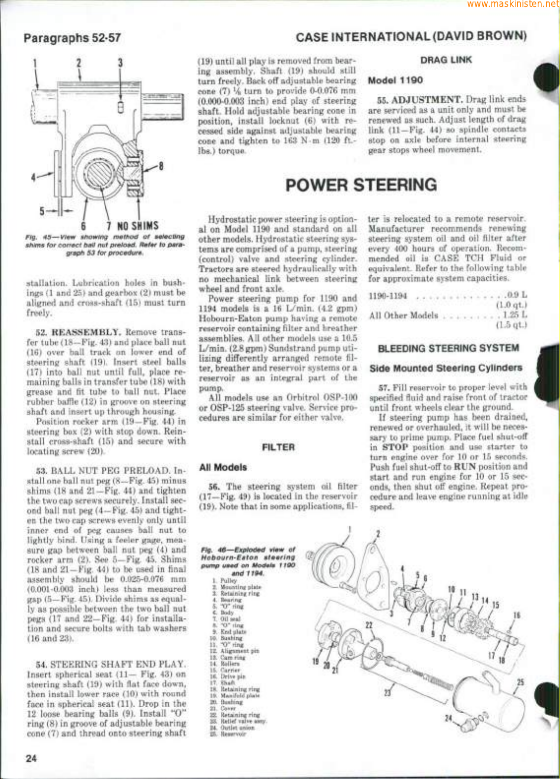
Paragraphs 52-57
www.maskinisten.net
CASE INTERNATIONAL (DAVID BROWN)
Fig. 45—View showing method of seiecting
6 7
shims for correct baii nut preioad. Refer to para-
graph 53 for procedure.
NO
SHIMS
stallation. Lubrication holes in bushings (1 and 25) and gearbox (2) must be
aligned and cross-shaft (15) must turn
freely.
52.
REASSEMBLY. Remove trans-
fer tube (18—Fig. 43) and place ball nut
(16) over ball track on lower end of
steering shaft (19). Insert steel balls
(17) into ball nut until full, place remaining balls in transfer tube (18) with
grease and fit tube to ball nut. Place
rubber baffle (12) in groove on steering
shaft and insert up through housing.
Position rocker arm (19—Fig. 44) in
steering box (2) with stop down. Reinstall cross-shaft (15) and secure with
locating screw (20).
53.
BALL NUT PEG PRELOAD. Install one ball nut peg (8—Fig. 45) minus
shims (18 and 21—Fig. 44) and tighten
the two cap screws securely. Install second ball nut peg (4—Fig. 45) and tighten the two cap screws evenly only until
inner end of peg causes ball nut to
lightly bind. Using a feeler gage, measure gap between ball nut peg (4) and
rocker arm (2). See 5—Fig. 45. Shims
(18 and 21—Fig. 44) to be used in final
assembly should be 0.025-0.076 mm
(0.001-0.003 inch) less than measured
gap (5—Fig. 45). Divide shims as equal-
ly as possible between the two ball nut
pegs (17 and 22—Fig. 44) for installation and secure bolts with tab washers
(16 and 23).
54.
STEERING SHAFT END PLAY.
Insert spherical seat (11— Fig. 43) on
steering shaft (19) with flat face down,
then install lower race (10) with round
face in spherical seat (11). Drop in the
12 loose bearing balls (9). Install *'O"
ring (8) in groove of adjustable bearing
cone (7) and thread onto steering shaft
(19) until all play is removed from bear-
ing assembly. Shaft (19) should still
turn freely. Back off adjustable bearing
cone (7)
Vg
turn to provide 0-0.076 mm
(0.000-0.003 inch) end play of steering
shaft. Hold adjustable bearing cone in
position, install locknut (6) with recessed side against adjustable bearing
cone and tighten to 163 N-m (120 ft.lbs.) torque.
POWER STEERING
Hydrostatic power steering is option-
al on Model 1190 and standard on all
other models. Hydrostatic steering systems are comprised of a pump, steering
(control) valve and steering cylinder.
Tractors are steered hydraulically with
no mechanical link between steering
wheel and front axle.
Power steering pump for 1190 and
1194 models is a 16 L/min. (4.2 gpm)
Hobourn-Eaton pump having a remote
reservoir containing filter and breather
assemblies. All other models use a 10.5
L/min. (2.8 gpm) Sundstrand pump utilizing differently arranged remote filter, breather and reservoir systems or a
reservoir as an integral part of the
pump.
All models use an Orbitrol ()SP-100
or OSP-125 steering valve. Service procedures are similar for either valve.
FILTER
All Models
56.
The steering system oil filter
(17—Fig. 49) is located in the reservoir
(19).
Note that in some applications, fil-
Fig, 45—Expioded view of
Hobourn-Eaton steering
pump used on Modeis 1190
and 1194.
1.
Pulley
2.
Mounting plate
3.
Retaining ring
4.
Bearing
5.
"0"
ring
6.
Body
7. Oil seal
8.
"0"
ring
9.
End
plate
10.
Bushing
11.
"0"
ring
12.
Alignment
13.
Cam
ring
14.
Rollers
15.
Carrier
16.
Drive
pin
17.
Shaft
18.
Retaining ring
19.
Manifold plate
20.
Bushing
21.
Cover
22.
Retaining ring
23.
Relief valve
24.
Outlet union
25.
Reservoir
pin
assy.
19
20
21
DRAG LINK
Model 1190
55.
ADJUSTMENT. Drag link ends
are serviced as a unit only and must be
renewed as such. Adjust length of drag
link (11—Fig. 44) so spindle contacts
stop on axle before internal steering
gear stops wheel movement.
ter is relocated to a remote reservoir.
Manufacturer recommends renewing
steering system oil and oil filter after
every 400 hours of operation. Recommended oil is CASE TCH Fluid or
equivalent. Refer to the following table
for approximate system capacities.
1190-1194 0.9 L
(1.0 qt.)
All Other Models 1.25 L
(1.5 qt.)
BLEEDING STEERING SYSTEM
Side Mounted Steering Cylinders
57.
Fill reservoir to proper level with
specified fluid and raise front of tractor
until front wheels clear the ground.
If steering pump has been drained,
renewed or overhauled, it will be necessary to prime pump. Place fuel shut-off
in STOP position and use starter to
turn engine over for 10 or 15 seconds.
Push fuel shut-off to RUN position and
start and run engine for 10 or 15 seconds,
then shut off engine. Repeat procedure and leave engine running at idle
speed.
24

SHOP MANUAL
www.maskinisten.net
Paragraphs 58-61
Manifold Port Timing Grooves
Fig. 47—When Installing manifold plate, be sure
side with port timing grooves faces away from
pump
cover.
With engine running at idle speed,
turn steering wheel one full turn in
each direction several times, but do not
allow front wheels to reach stops. Recheck fluid level in reservoir and fill as
necessary.
NOTE:
placement rams are used, oii level in
remote reservoir must be 38 mm (1^2
inches) above element when steering is
turned fuiiy to right.
Where side mounted equal dis-
With engine running at idle speed,
turn steering wheel until front wheels
reach stops in both directions several
times.
Do not hold front wheels against
stops for more than a few seconds at a
time.
Lower front of tractor and fill reser-
voir to proper level.
Repeat procedure if operation is not
satisfactory.
Transverse Mounted Steering Cy-
linders
58.
Fill reservoir to proper level and
if pump has been drained, renewed or
overhauled, prime pump as follows:
With fuel shut-off in STOP position,
crank engine with starter for about 15
seconds. Move fuel shut-off to RUN
position. Start engine and run for about
15 seconds, then stop engine. Check reservoir fiuid level, then start engine and
operate at idle speed.
With engine running at idle speed,
reservoir filled to proper level and front
wheels raised off the ground, loosen
bleed screw on left side of steering
cylinder one full turn. Turn steering
wheel right until front wheels reach
their stop, then tighten left-hand bleed
screw. Loosen bleed screw on right side
of steering cylinder one full turn. Turn
steering wheel left until front wheels
reach their stop, then tighten right-
hand bleed screw. Turn front wheels
from stop to stop several times to check
operation. Repeat procedure if opera-
tion is not satisfactory. Stop engine.
lower front wheels to ground and fill
reservoir to proper level.
Aii Other Modeis
59.
The steering hydraulic system on
models equipped with standard steering cylinders is basically self-bleeding.
To purge trapped air from the system,
first be sure reservoir is filled to proper
level. With engine running, turn steering wheel from lock to lock several
times until steering operation is satisfactory. Check reservoir for correct oil
level again and fill if necessary.
SYSTEM OPERATiNG PRESSURE
Aii Modeis
60,
A pressure test of power steering
circuit will disclose whether pump, relief valve or some other unit in system
is malfunctioning. To check pressure,
disconnect pump outlet line and install
a 0-20000 kPa (0-3000 psi) pressure gage
into pump outlet port.
NOTE:
note pressure gage reading. Pump is operating at maximum pressure during test and
fluid overheating and pump damage may
result if engine is operated for a iong
od of time.
Run engine oniy iong enough to
peri-
Start and run engine at 1500 rpm
only long enough to read pressure gage.
Pump pressure for 1190 and 1194 models should be 7930 kPa (1150 psi). Pressure for all other models should be
10340 kPa (1500 psi). If pump fails to
reach specified pressure, remove and
examine pump.
STEERiNG PUMP
Modeis 1190-1194
61.
R&R AND OVERHAUL. The
belt driven pump is mounted on left
side of engine. To remove pump, first
remove air intake precleaner and
muffler. Raise the hood and remove left
side panel and rail. Disconnect pump
inlet and outlet lines and drain oil.
Loosen pump retaining bolts and remove drive belt from pulley. Remove
mounting bolts and remove pump.
To disassemble, remove pulley
(1 —
Fig. 46) and mounting plate (2). Remove
outlet union (24). Tap around edge of oil
reservoir (25) to separate reservoir
from pump body. Remove retaining
ring (22), then remove body (6) from
shaft and cover assembly. Remove two
screws from end plate (9). Carefully
separate end plate, cam ring (13), mani-
fold plate (19), rollers (14), carrier (15)
and shaft (17).
NOTE:
is not recommended as repiacement parts
are not avaiiabie. if valve is disassembled
for cleaning and tnspecton, note exact
position of vaive piug. The piug must be
instaiied in its originai position or reiief
pressure setting wiii be affected.
Disassembiy of reiief valve (23)
Inspect all parts for excessive wear
and damage. An "0** ring and seal kit,
front bearing and pumping element and
shaft assembly are available for service.
To reassemble, install drive key (16)
and carrier (15) on shaft. Position manifold plate on the cover with timing
grooves (Fig. 47) facing up. Assemble
shaft into bore of manifold plate. Install cam ring (Fig. 48) with cam mark
towards drive end of shaft as shown,
then install rollers in carrier. Position
alignment pin in smallest hole in cam
ring. Install end plate (9—Fig. 46) and
the two retaining screws, but do not
tighten screws.
It is recommended that an alignment
tool be made from an old pump body by
drilling two holes through end of the
body to align with end plate screws.
Install tool over pumping element to
align components. Check for free rotation of shaft, then securely tighten the
two screws through the holes of the
tool. Remove the tool.
Install new "0" rings and shaft oil
seal and lubricate with clean oil before
reassembling. Protect lip of seal, then
install body (6—Fig. 46) over pump
assembly. Install cover retaining ring
(22).
Install reservoir (25) aligning outlet holes in pump and reservoir. Install
outlet union (24) with a new "0" ring.
Install pulley and tighten retaining nut
to 16 N-m (12 ft.-lbs.) torque. Be sure
pump shaft turns freely.
To reinstall pump, reverse the re-
moval procedure.
Alignmerit Pin Hole
Cam Mark
Fig. 48—Install cam ring with cam mark towards
drive end of shaft. Install alignment pin in small-
est hole in cam ring.
25
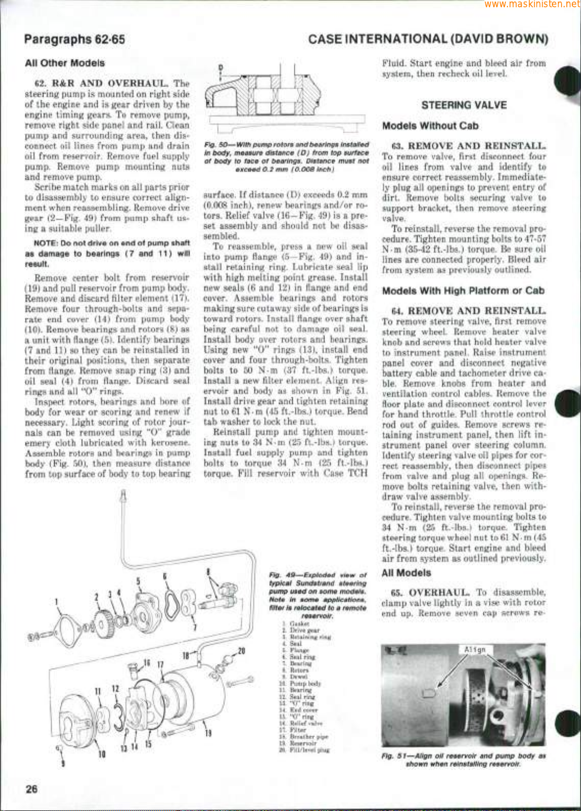
Paragraphs 62-65
www.maskinisten.net
CASE INTERNATIONAL (DAVID BROWN)
AM
other Models
62.
R&R AND OVERHAUL. The
steering pump is mounted on right side
of the engine and is gear driven by the
engine timing gears. To remove pump,
remove right side panel and rail. Clean
pump and surrounding area, then disconnect oil lines from pump and drain
oil from reservoir. Remove fuel supply
pump. Remove pump mounting nuts
and remove pump.
Scribe match marks on all parts prior
to disassembly to ensure correct alignment when reassembling. Remove drive
gear (2—Fig. 49) from pump shaft using a suitable puller.
NOTE:
Do not drive on end of pump shaft
as damage to bearings (7 and 11) wili
resuit.
Remove center bolt from reservoir
(19) and pull reservoir from pump body.
Remove and discard filter element (17).
Remove four through-bolts and separate end cover (14) from pump body
(10).
Remove bearings and rotors (8) as
a unit with fiange (5). Identify bearings
(7 and 11) so they can be reinstalled in
their original positions, then separate
from fiange. Remove snap ring (3) and
oil seal (4) from fiange. Discard seal
rings and all *'O" rings.
Inspect rotors, bearings and bore of
body for wear or scoring and renew if
necessary. Light scoring of rotor journals can be removed using *'O*' grade
emery cloth lubricated with kerosene.
Assemble rotors and bearings in pump
body (Fig. 50), then measure distance
from top surface of body to top bearing
14
15
\ " "
Fig. 50—With pump rotors and
in
body,
measure distance (D) from top surface
of body to face of bearings. Distance must not
exceed 0.2 mm (0.008 inch)
bearings
Instaiied
surface. If distance (D) exceeds 0.2 mm
(0.008 inch), renew bearings and/or rotors.
Relief valve (16—Fig. 49) is a preset assembly and should not be disassembled.
To reassemble, press a new oil seal
into pump fiange (5—Fig. 49) and install retaining ring. Lubricate seal lip
with high melting point grease. Install
new seals (6 and 12) in fiange and end
cover. Assemble bearings and rotors
making sure cutaway side of bearings is
toward rotors. Install fiange over shaft
being careful not to damage oil seal.
Install body over rotors and bearings.
Using new '*0" rings (13), install end
cover and four through-bolts. Tighten
bolts to 50 N-m (37 ft.-lbs.) torque.
Install a new filter element. Align reservoir and body as shown in Fig. 51.
Install drive gear and tighten retaining
nut to 61 N-m (45 ft.-lbs.) torque. Bend
tab washer to lock the nut.
Reinstall pump and tighten mounting nuts to 34 N-m (25 ft.-lbs.) torque.
Install fuel supply pump and tighten
bolts to torque 34 N-m (25 ft.-lbs.)
torque. Fill reservoir with Case TCH
Fig. 49—Exploded view of
typicai Sundstrand steering
pump used on some models.
Note in some applications,
filter is reiocated to a remote
19
reservoir.
1.
Gasket
2.
Drive gear
3.
Retaining ring
4.
Seal
5.
Flange
6. Seal ring
7.
Bearing
8. Rotors
9. Dowel
10.
Pump body
11.
Bearing
12.
Seal ring
13.
"0" ring
14.
End cover
15.
"0" ring
16.
Relief valve
17.
Filter
18.
Breather pipe
19.
Reservoir
20.
Fill/level plug
Fluid. Start engine and bleed air from
system, then recheck oil level.
STEERING VALVE
Models Without Cab
63.
REMOVE AND REINSTALL.
To remove valve, first disconnect four
oil lines from valve and identify to
ensure correct reassembly. Immediately plug all openings to prevent entry of
dirt. Remove bolts securing valve to
support bracket, then remove steering
valve.
To reinstall, reverse the removal procedure. Tighten mounting bolts to 47-57
N-m (35-42 ft.-lbs.) torque. Be sure oil
lines are connected properly. Bleed air
from system as previously outlined.
Models With High Platform or Cab
64.
REMOVE AND REINSTALL.
To remove steering valve, first remove
steering wheel. Remove heater valve
knob and screws that hold heater valve
to instrument panel. Raise instrument
panel cover and disconnect negative
battery cable and tachometer drive cable.
Remove knobs from heater and
ventilation control cables. Remove the
fioor plate and disconnect control lever
for hand throttle. Pull throttle control
rod out of guides. Remove screws retaining instrument panel, then lift instrument panel over steering column.
Identify steering valve oil pipes for correct reassembly, then disconnect pipes
from valve and plug all openings. Remove bolts retaining valve, then withdraw valve assembly.
To reinstall, reverse the removal procedure. Tighten valve mounting bolts to
34 N-m (25 ft.-lbs.) torque. Tighten
steering torque wheel nut to
61 N • m
(45
ft.-lbs.) torque. Start engine and bleed
air from system as outlined previously.
All Models
65.
OVERHAUL. To disassemble,
clamp valve lightly in a vise with rotor
end up. Remove seven cap screws re-
Fig, 51—Align oil reservoir and pump body as
shown when reinstaiiing reservoir.
26
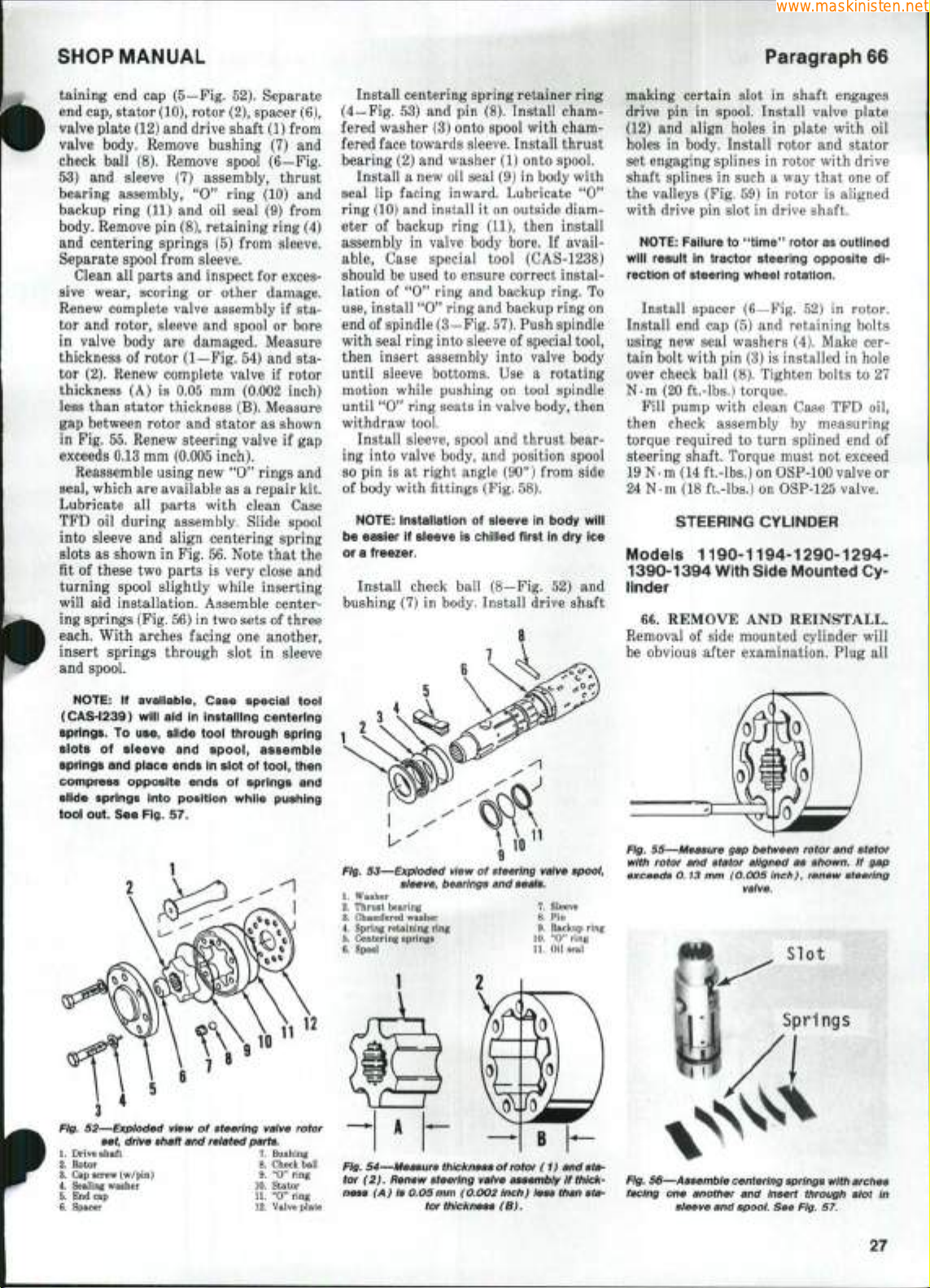
SHOP MANUAL
www.maskinisten.net
Paragraph
66
taining
end cap
(5—Fig. 52). Separate
end cap, stator (10), rotor (2), spacer (6),
valve plate (12) and drive shaft (1) from
valve body. Remove bushing
check ball
53)
and
bearing assembiy,
backup ring (11)
(8).
Remove spool (6—Fig.
sleeve
(7)
assembly, thrust
"0"
and oil
ring
seal
(7) and
(10) and
(9)
from
body. Remove pin (8), retaining ring (4)
and centering springs
(5)
from sleeve.
Separate spool from sleeve.
Clean
all
sive wear, scoring
or
Renew complete valve assembly
parts and inspect
tor
and
in valve body
rotor, sleeve
thickness
of
rotor (1—Fig. 54)
and
are
damaged. Measure
tor (2). Renew complete valve
thickness
(A) is 0.05 mm
for
exces-
other damage.
if sta-
spool
or
bore
and sta-
if
rotor
(0.002 inch)
less than stator thickness (B). Measure
gap between rotor and stator
in Fig. 55. Renew steering valve
as
shown
if
gap
exceeds 0.13 mm (0.005 inch).
Reassemble using new
**0"
rings and
seal, which are available as a repair kit.
Lubricate
TFD
into sleeve
slots
fit
all
oil
as
of these two parts
parts with clean Case
during assembly. Slide spool
and
shown
align centering spring
in
Fig. 56. Note that
is
very close
the
and
turning spool slightly while inserting
will
aid
ing springs (Fig. 56)
each. With arches facing
insert springs through slot
installation. Assemble center-
in
two sets
one
of
three
another,
in
sleeve
and spool.
Install centering spring retainer ring
(4_Fig.
53) and pin
(8). Install chamfered washer (3) onto spool with chamfered face towards sleeve. Install thrust
bearing (2) and washer (1) onto spool.
Install a new oil seal (9)
seal
lip
facing inward. Lubricate
ring (10) and install
eter
of
backup ring
assembly
able.
should be used
lation
use,
in
valve body bore.
Case special tool (CAS-1238)
to
of
"0" ring
ensure correct instal-
and
install "0" ring and backup ring on
end of spindle (3—Fig.
with seal ring into sleeve
in
body with
it
on outside diam-
(11),
then install
If
avail-
backup ring.
57).
Push spindle
of
special tool,
"0"
To
then insert assembly into valve body
until sleeve bottoms.
motion while pushing
until
"0^*
ring seats
Use a
on
in
rotating
tool spindle
valve body, then
withdraw tool.
Install sleeve, spool and thrust bearing into valve body,
so
pin is at
right angle (90°) from side
and
position spool
of body with fittings (Fig. 58).
NOTE:
instaiiation of sieeve in body witi
be easier if sieeve is chiiied first in dry ice
or a freezer.
Install check ball (8-Fig.
bushing (7)
in
body. Install drive shaft
52) and
making certain slot
drive
(12)
holes
pin in
and
in
spool. Install valve plate
align holes
body. Install rotor
set engaging splines
shaft splines
in
the valleys (Fig. 59)
with drive pin slot
NOTE:
Faiiure to "time'* rotor as outiined
wili resuit In tractor steering opposite direction of steering wheei rotation.
Install spacer (6—Fig.
Install
end cap (5) and
using
new
seal washers (4). Make
tain bolt with pin (3)
over check ball (8). Tighten bolts
in
shaft engages
in
plate with
and
stator
in
rotor with drive
such a way that one
in
rotor
is
aligned
in
drive shaft.
52) in
rotor.
retaining bolts
cer-
is
installed
in
to 27
oil
of
hole
N-m (20 ft.-lbs.) torque.
Fill pump with clean Case
then check assembly
torque required
to
turn splined
steering shaft. Torque must
19 N.m (14 ft.-lbs.) on OSP-100 valve
by
measuring
not
TFD oil,
end of
exceed
or
24 N-m (18 ft.-lbs.) on OSP-125 valve.
STEERiNG CYLiNDER
Modeis 1190-1194-1290-1294-
1390-1394 With Side Mounted Cy-
iinder
66.
REMOVE
Removal
of
be obvious after examination. Plug
AND
REINSTALL.
side mounted cylinder will
all
NOTE:
(CAS-i239) wiii aid in instaiiing centering
springs. To use, siide tooi tiirough spring
siots of sieeve and spooi, assembie
springs and piace ends in siot of
compress opposite ends of springs and
siide springs into position whiie pushing
tooi out. See Fig. 57.
Fig. 52—Expioded view
1.
2.
3.
4.
5.
6. Spacer
tf available, Case special tooi
tooi,
then
of
set, drive shaft and reiated parts.
Drive shaft
Rotor
Cap screw (w/pin)
Sealing washer
End cap 11. "0" ring
7.
8.
12.
9.
10.
steering vaive rotor
Bushing
Check ball
"0" ring
Stator
Valve plate
Fig. 53—Expioded view
1.
Washer
2.
Thrust bearing
3.
Chamfered washer
4.
Spring retaining ring
5.
Centering springs
S. Spool
Fig. 54—Measure
tor
ness
sieeve, bearings and seals.
(2).
Renew steering vaive assembiy
(A)
thicitness
is
0.05
mm (0.002 inch) iess than sta-
tor thickness
of
steering vaive spooi,
7.
Sleeve
8.
Pin
9. Backup ring
10.
"0" ring
11.
Oil seal
of rotor
(1)
and sta-
(B).
if
thick-
Fig. 55—Measure gap between rotor and stator
with rotor
exceeds
and
stator aiigned
0.13
mm (0.005 inch), renew steering
as
shown,
if gap
Slot
Spriiigs
Fig. 56—Aasembie centering
facing
one
another
sleeve and
and
spooi.
springs with
Insert through siot
See Fig.
arches
57.
in
27
Paragraphs 67-69
www.maskinisten.net
CASE INTERNATIONAL (DAVID BROWN)
Open hydraulic fittings
to
prevent entry
of dirt.
After reinstalling cylinder, bleed sys-
tem
as
outlined
67.
OVERHAUL. Clear cylinder
oil
as
necessary
through
its
snap rings
pull
rod
in
paragraph
by
moving piston
full stroke. Remove
(22 and
(14), piston (15)
23—Fig.
and
57.
60),
sleeve
from cylinder (1). Remove bolt (19)
piston (15). Remove
rings,
backup rings, seal rings
and
discard
all
scraper seal.
Remove
remove spring
sleeve
Remove
Cylinder must
score marks. Piston
end
(11) and
and
discard
caps
(2 and 13) and
(12),
spool valve
nonreturn valve
"0"
rings.
be
smooth
and
and rod
free
must
n
g, 53—Install sleeve into body with drive pin
right angie
Fig.
59—Rotor is properiy
by
engaging drive shaft spiines
one
of
the
valleys
(90") to
fitting side
"timed" to vaivespooi
in rotor
is
siot in drive shaft.
aiigned
of
body.
in
such a way that
with
of
rod
two
then
(30)
and
**0"
and
and
(3).
of
be
at
drive pin
Fig. 57—View showing
method
of
free
of
nicks
ing springs
rings using Case special
or
burrs. Slight blemishes
instaiiing
tools.
1.
Special tool (CAS-1239)
2.
Centering springs
3.
Special tool (CAS-1238)
spindle
4.
Special tool (CAS-1238)
sleeve
and
center-
shaft seai
may be removed using fine emery paper
lubricated with kerosene,
must
be
thoroughly clean before reas-
but all
parts
sembly.
Soak backup rings
oil
for a
minimum
to reassembly. Lubricate
ing assembly. Make sure spool
moves freely. Reassemble
in
clean hydraulic
of 30
minutes prior
all
by
parts
dur-
(11)
reversing
disassembly procedure.
Models 1490-1494-1594-1690
With Transverse Mounted Cylinder
(Two-Wheel Drive)
68.
REMOVE
To remove steering cylinder, first
move front axle
graph
4.
(15—Fig.
Disconnect
61).
pipes from each union (35). Note that
snap ring (37) retains
models. Remove both unions
ing washers (34). Remove retaining
(5)
and
cylinder
pivot
and
Remove screws securing ball pegs
(12),
then remove ball pegs. Retain
shims
(13) for use in
move cylinder from fork.
If original cylinder, ball pegs
fork
are
being reused, reinstall cylinder
in fork using
original shims (13).
If cylinder, ball pegs
newed, ball
be adjusted
0.076
mm
Assemble cylinder
seal rings
and tighten retaining screws. Install
upper ball
of shims
ment
(11)
(13) to
on
ball pegs. Remove relief valve
and
position dial indicator probe
through relief valve hole
cylinder. Raise
measure movement. Remove shims
equal
to
dial indicator reading plus 0.05
mm (0.002 inch)
load. Reinstall relief valve (11).
AND
REINSTALL.
as
outlined
tie
in
rods from fork
Disconnect hydraulic
the
pipes on some
and
pin (10),
then withdraw
fork assembly from axle.
reassembly.
new
seal rings
peg
shim thickness should
to
provide preload
(0.001-0.003 inch)
in
(14).
peg
fork using
Install lower ball
with sufficient amount
or
(14) and
fork
of
as
ensure cylinder move-
so it
and
lower cylinder
to
provide desired
contacts
re-
para-
spac-
nut
Re-
and
is re-
0.025-
follows:
new
peg
and
pre-
Install cylinder
without spacing washers
and
fork assembly
(34).
special unions (35), then move cylinder
to one
end and
measure
gap at
end with a feeler gage. Proper setting
between 0.13
and 0.025
move unions
washers (34)
end
to
unions
lbs.) torque. Install pivot
tighten
mm
(0.005 inch) clearance
mm
(0.001 inch) preload.
and
position spacing
of
equal thickness
obtain proper setting. Install
and
tighten
to
205
N • m
pin (10) and
nut
(5) until there
is
movement, then install cotter pin. Complete installation, reinstall front axle
and bleed system
as
previously
lined.
69.
OVERHAUL. Clear cylinder
oil
as
necessary
through
its
snap ring (28—Fig.
sembly
(27)
Pull piston
der.
On
early models, remove retaining
bolts,
locking plate (22), split ring
and piston (20).
and discard
by
moving piston
complete stroke. Remove
61) and
from each
rod and
all
**0*'
end of
piston from cylin-
On all
models, remove
rings, backup rings
and seal rings.
Cylinder bore should
free
of
score marks. Piston
rod must
be
free
of
be
nicks
smooth
Slight blemishes may be removed using
fine emery cloth lubricated with kerosene.
a
Fig. 60—Exploded view
steering cylinder used
1.
Cylinder tube
2.
End
3.
Nonreturn valve
4.
"0"
5.
Fitting
6.
Tie rod end
7.
"0"
8.
"0"
9.
"0"
10.
"O"ring
11.
Spool valve & sleeve
12.
Spring
13.
End
14.
Piston
15.
Piston
16.
plate
17.
ring
19.
20.
21.
ring
22.
ring
23.
ring
24.
25.
27.
plate
28.
rod 29.
30.
of
typical side mounted
on
some two-wheei drive
tractors.
18.
26.
Install
opposite
Re-
at
each
(150
no free end
out-
of
rod
sleeve
as-
cylinder.
(21)
and
and
piston
or
burrs.
Backup ring
"0"
ring
Backup ring
Bolt
Tie rod end
Dust shield
Snap ring
Snap ring
Scraper seal
Seal ring
Backup ring
"0"
ring
Backup ring
"0"
ring
Sleeve
is
ft.-
28
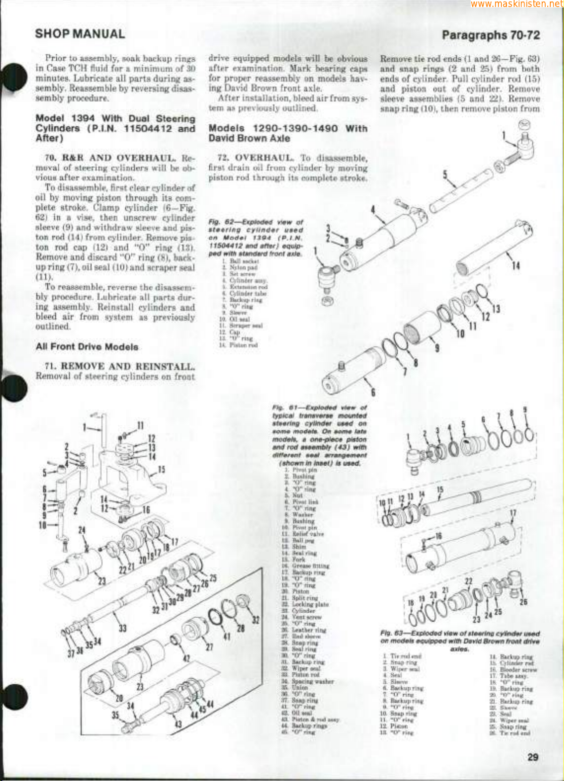
SHOP MANUAL
www.maskinisten.net
Prior
to
in Case TCH fluid
minutes. Lubricate
sembly. Reassemble
sembly procedure.
Model
Cylinders (P.I.N. 11504412
After)
70.
moval
vious after examination.
To disassemble, first clear cylinder of
oil
by
plete stroke. Clamp cylinder (6—Fig.
62)
sleeve
ton
ton
Remove
up ring (7),
(11).
To reassemble, reverse
bly procedure. Lubricate
ing assembly. Reinstall cylinders
bleed
outlined.
All Front Drive Modeis
assembly, soak backup rings
for a
minimum
all
parts during
by
reversing disas-
1394
R&R AND
of
With Duai Steering
OVERHAUL.
steering cylinders will
moving piston through
in a
vise, then unscrew cylinder
(9) and
rod
withdraw sleeve
(14) from cylinder. Remove
rod cap (12) and *'O"
and
discard "0" ring (8), back-
oil
seal (10)
and
the
all
air
from system
as
of 30
as-
and
Re-
be ob-
its com-
and pis-
pis-
ring
(13).
scraper seal
disassem-
parts
dur-
and
previously
drive equipped models will
be
obvious
after examination. Mark bearing caps
for proper reassembly
on
models
hav-
ing David Brown front axle.
After installation, bleed
tem
as
previously outlined.
Modeis 1290-1390-1490
air
from sys-
With
David Brown Axle
72.
OVERHAUL.
first drain
piston
Fig.
steering cyiinder used
on Model
11504412 and
ped
oil
rod
62—Expioded
with standard front
1.
Ball socket
2.
Nylon
3.
Set screw
4.
Cylinder assy.
5.
Extension
6.
Cylinder tube
7.
Backup ring
8.
"0" ring
9.
Sleeve
10.
Oil seal
U.
Scraper seal
12.
Cap
13.
"0" ring
14.
Piston
from cylinder
through
13g4
after)
pad
rod
rod
To
its
complete stroke.
view
of
(P.I.N.
equip-
axie.
disassemble,
by
moving
Paragraphs 70-72
Remove
and snap rings
ends
and piston
sleeve assemblies
snap ring (10), then remove piston from
tie rod
ends (1
and
(2 and 25)
of
cylinder. Pull cylinder
out of
cylinder. Remove
(5 and 22).
26-~Fig.
from both
rod (15)
Remove
13
12
63)
11
10
71.
REMOVE
Removal
AND
of
steering cylinders
REINSTALL.
on
front
11
Fig, 61—Expioded view
typicai transverse mounted
steering cylinder used
some models.
modeis, a one-piece piston
and
rod
different seai arrangement
(shown
1.
2.
Bushing
3.
"C'ring
4
"O" ring
5.
Nut
6.
7.
8.
9.
10.
Pivot pin
11.
Relief valve
12.
Ball
13.
Shim
14.
Seal ring
15.
Fork
16.
Grease Btting
17.
Backup ring
18.
'*O"ring
19.
"0" ring
20.
Piston
21.
Split ring
22.
Locking plate
23.
Cylinder
24.
Vent screw
25.
"0" ring
26.
Leather ring
27.
End sleeve
28.
Snap ring
29.
Seat ring
30.
"0" ring
31.
Backup ring
32.
Wiper seal
33.
Piston
34.
Spacing washer
35.
Union
36.
"0" ring
37.
Snap ring
41.
"0" ring
42.
Oil seal
43.
Piston & rod assy.
44.
Backup rings
45.
"0" ring
assembiy
in
Pivot
pin
Pivot link
"0" ring
Washer
Bushing
peg
rod
On
inset)
of
on
some iate
(43)
with
is
used.
23
Fig. 63—Expioded view of steering cyiinder used
on modeis equipped
1.
Tie rod end
2.
Snap ring
3.
Wiper seal
4.
Seal
17.
5.
Sleeve
18.
6.
Backup ring
7.
"0" ring
8.
9.
10.
11.
12.
13.
20.
Backup ring
"O" ring
22.
Snap ring
"0" ring
24.
Piston
25.
"0" ring
26.
with
David
axies.
14.
15.
16.
19.
21.
23.
Brown
front drive
Backup ring
Cylinder
rod
Bleeder screw
Tube assy.
"O" ring
Backup ring
"O" ring
Backup ring
Sleeve
Seal
Wiper seal
Snap ring
Tie rod end
29
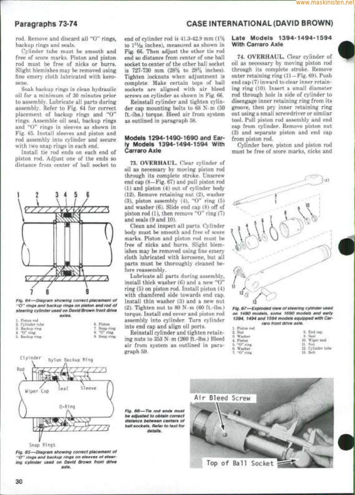
Paragraphs 73-74
www.maskinisten.net
CASE INTERNATIONAL (DAVID BROWN)
rod. Remove and discard all "0*' rings,
backup rings and seals.
Cylinder tube must be smooth and
free of score marks. Piston and piston
rod must be free of nicks or burrs.
Slight blemishes may be removed using
fine emery cloth lubricated with kerosene.
Soak backup rings in clean hydraulic
oil for a minimum of 30 minutes prior
to assembly. Lubricate all parts during
assembly. Refer to Fig. 64 for correct
placement of backup rings and "0**
rings.
Assemble oil seal, backup rings
and '*0" rings in sleeves as shown in
Fig. 65. Install sleeves and piston and
rod assembly into cylinder and secure
with two snap rings in each end.
Install tie rod ends on each end of
piston rod. Adjust one of the ends so
distance from center of ball socket to
Fig.
64—Diagram showing
"O"
rings
and
steering cylinder used
1.
Piston rod
2.
Cylinder tube 6. Piston
3.
Backup ring 7. Snap ring
4.
"O" ring 8. "O" ring
5.
Backup ring 9. Snap ring
Clyinder
backup
correct
rings
on
on
David Brown
axles.
Backup Ring
piston
piacement
and
rod of
front
drive
end of cylinder rod is 41.3-42.9 mm
to l"/i6 inches), measured as shown in
Fig. 66. Then adjust the other tie rod
end so distance from center of one ball
socket to center of the other ball socket
is 727-730 mm {2^% to 28V4 inches).
Tighten locknuts when adjustment is
complete. Make certain tops of ball
sockets are aligned with air bleed
screws on cylinder as shown in Fig. 66.
Reinstall cylinder and tighten cylinder cap mounting bolts to 68 N-m (50
ft-lbs.) torque. Bleed air from system
as outlined in paragraph 58.
Models 1294-1490-1690 and Early Models 1394-1494-1594 With
Carraro Axie
73.
OVERHAUL. Clear cylinder of
oil as necessary by moving piston rod
through its complete stroke. Unscrew
end cap (8—Fig. 67) and pull piston rod
(1) and piston (4) out of cylinder body
(12).
Remove retaining nut (2), washer
(3),
piston assembly (4), **0" ring (5)
and washer (6). Slide end cap (8) off of
piston rod (1), then remove "0" ring (7)
and seals (9 and 10).
Clean and inspect all parts. Cylinder
body must be smooth and free of score
marks. Piston and piston rod must be
free of nicks and burrs. Slight blemishes may be removed using fine emery
cloth lubricated with kerosene, but all
parts must be thoroughly cleaned before reassembly.
Lubricate all parts during assembly,
install thick washer (6) and a new "0"
ring (5) on piston rod. Install piston (4)
with chamfered side towards end cap.
of
Install thin washer (3) and a new nut
(2).
Tighten nut to 80 N-m (60 ft.-lbs.)
torque. Install end cover and piston rod
assembly into cylinder. Turn cylinder
into end cap and align oil ports.
Reinstall cylinder and tighten retaining nuts to 353 N-m (260 ft.-lbs.) Bleed
air from system as outlined in paragraph 59.
Late Models 1394-1494-1594
With Carraro Axie
74.
OVERHAUL. Clear cylinder of
oil as necessary by moving piston rod
through its complete stroke. Remove
outer retaining ring (11—Fig. 69). Push
end cap (7) inward to clear inner retaining ring (10). Insert a small diameter
rod through hole in side of cylinder to
disengage inner retaining ring from its
groove, then pry inner retaining ring
out using a small screwdriver or similar
tool. Pull piston rod assembly and end
cap from cylinder. Remove piston nut
(3) and separate piston and end cap
from piston rod.
Cylinder bore, piston and piston rod
must be free of score marks, nicks and
Fig.
67—Expioded view
on 1490
1.
2.
3.
4.
5.
6. Washer 12. Cylinder tube
7.
models,
1394,
1494
and
Piston rod
Nut 8. End cap
Washer 9. Seal
Piston 10. Wiper seal
"0" ring U. Nut
"0" ring 13. Bolt
raro front
of
some 1690 models and early
1594
steering cylinder used
modeis equipped with
drive
axle.
Car-
Snap Rings
Fig.
65—Diagram showing
*'O" rings and
ing cylinder used on David Brown front drive
backup
rings on
axie.
correct
30
placement
sieeves
of
steer-
Fig. 66—Tie rod ends must
lye
adjusted
distance between
baii
of
sockets.
detaiis.
to
obtain
Refer
correct
centers of
to text
for
Air Bleed Screw
Top of Ball Socket
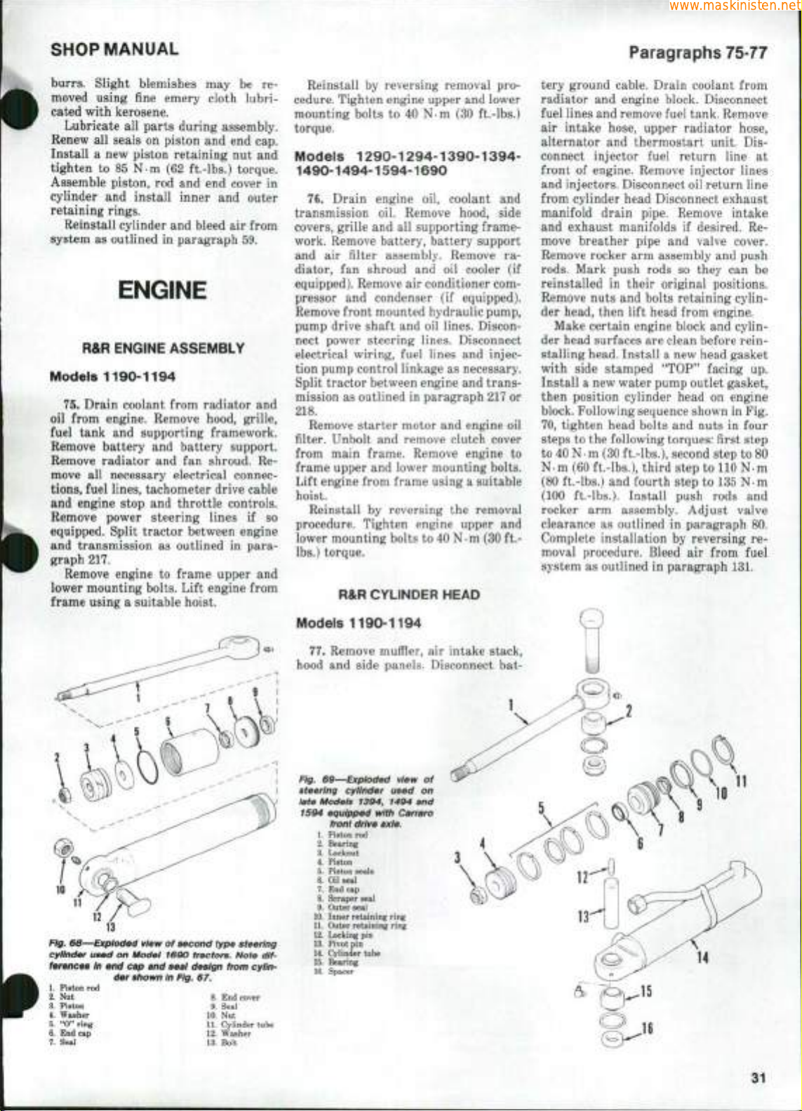
SHOP MANUAL
www.maskinisten.net
burrs.
Slight blemishes
may be re-
moved using fine emery cloth lubri-
cated with kerosene.
Lubricate
Renew
Install
tighten
Assemble piston,
cylinder
all
all
a new
parts during assembly.
seals
on
piston
piston retaining
to 85 N-m (62
rod and end
and
install inner
and end cap.
nut and
ft.-lbs.) torque.
cover
and
in
outer
retaining rings.
Reinstall cylinder
system
as
outlined
and
in
paragraph
bleed
air
from
59.
ENGINE
R&R ENGINE ASSEMBLY
Models 1190-1194
75.
Drain coolant from radiator
oil from engine. Remove hood, grille,
fuel tank
Remove battery
Remove radiator
move
tions,
and engine stop
and
supporting framework.
and
battery support.
all
and fan
necessary electrical connec-
shroud.
fuel lines, tachometer drive cable
and
throttle controls.
Remove power steering lines
equipped. Split tractor between engine
and transmission
as
outlined
graph 217.
Remove engine
to
frame upper
lower mounting bolts. Lift engine from
frame using a suitable hoist.
if so
in
and
Re-
para-
and
Reinstall
cedure. Tighten engine upper
mounting bolts
by
reversing removal
to 40 Nm (30
and
ft.-lbs.)
pro-
lower
torque.
Models 1290-1294-1390-1394-
1490-1494-1594-1690
76.
Drain engine
transmission
covers, grille
oil.
and all
work. Remove battery, battery support
and
air
diator,
filter assembly. Remove
fan
shroud
equipped). Remove
pressor
and
condenser
Remove front mounted hydraulic pump,
pump drive shaft
nect power steering lines. Disconnect
electrical wiring, fuel lines
tion pump control linkage
Split tractor between engine
mission
as
outlined
218.
Remove starter motor
filter. Unbolt
and
from main frame. Remove engine
frame upper
and
Lift engine from frame using a suitable
hoist.
Reinstall
by
procedure. Tighten engine upper
lower mounting bolts
lbs.) torque.
R&R CYLINDER HEAD
Models 1190-1194
oil,
coolant
and
Remove hood, side
supporting frame-
and oil
air
and oil
in
cooler
conditioner com-
(if
equipped).
lines. Discon-
and
injec-
as
necessary.
and
trans-
paragraph 217
and
engine
remove clutch cover
lower mounting bolts.
reversing
to
40
the
N • m
removal
(30
ra-
(if
or
oil
to
and
ft.-
Paragraphs 75-77
tery ground cable. Drain coolant from
radiator
fuel lines and remove fuel tank. Remove
air intake hose, upper radiator hose,
alternator
connect injector fuel return line
front
and injectors. Disconnect oil return line
from cylinder head Disconnect exhaust
manifold drain pipe. Remove intake
and exhaust manifolds
move breather pipe
Remove rocker
rods.
reinstalled
Remove nuts
der head, then lift head from engine.
der head surfaces
stalling head. Install a new head gasket
with side stamped
Install a new water pump outlet gasket,
then position cylinder head
block. Following sequence shown
70,
steps
to 40 N-m (30 ft.-lbs.), second step
N-m (60 ft.-lbs.), third step
(80 ft.-lbs.)
(100 ft.-lbs.). Install push rods
rocker
clearance
Complete installation
moval procedure. Bleed
system
and
engine block. Disconnect
and
thermostart unit.
of
engine. Remove injector lines
if
desired.
and
Mark push rods
arm
in
their original positions.
and
bolts retaining cylin-
valve cover.
assembly
so
they
Make certain engine block
are
clean before rein-
"TOP"
tighten head bolts
to the
following torques: first step
and
arm
assembly. Adjust valve
as
outlined
and
fourth step
in
paragraph
by
nuts
reversing
air
as
outlined
in
paragraph 131.
Dis-
Re-
and
push
can be
and
cylin-
facing
up.
on
engine
in
Fig.
in
four
to 80
to
110
N-m
to
135
N-m
and
from fuel
at
80.
re-
10
Ffg. 68—Exploded view
cylinder used
ferences
1.
Piston
2.
Nut 8.
3.
Piston
4.
Washer
5.
"O" ring
6.
End cap
7. Seal
on
in end cap and
der shown
rod
9.
10. Nut
11.
12.
13.
of
Modei
second type steering
1690
tractors. Note
seal design from cyiin-
in
Fig.
67.
dif-
End cover
Seal
Cylinder tube
Washer
Bolt
77.
Remove muffler,
hood
and
side panels. Disconnect
Fig. 69—Bxpioded view
steering cyiinder used
iate Modeis
1594 equipped witii Carraro
1394, 1494 and
front drive axie,
1.
Piston
rod
2.
Bearing
3.
Locknut
4.
Piston
5. Piston seals
6.
Oil
seal
7.
End cap
8. Scraper seal
9. Outer seal
10.
Inner retaining ring
11.
Outer retaining ring
12.
Locking
13.
14.
15.
16.
pin
Pivot
pin
Cylinder tube
Bearing
Spacer
on
air
intake stack,
of
bat-
31
 Loading...