

Page 1

Syncro 1496/1496R (V.32bis)
Reference Manual
©Case Communications Ltd 2000
X450-310851 Issue 2 0-1 Rev.5
Unit 15, Riverside Business Centre, Victoria Street, High Wycombe, Bucks HP11 2LT
Web: www.casecomms.com Email: sales@casecomms.com
Tel (UK): 08700 263 740 Tel (International): +44 (0) 1494 833 740
Fax (UK): 08700 263 741 Fax (International): +44 (0) 1494 833 741
Page 2

STATUTORY NOTICES
LITHIUM BATTERY
The lithium used in the battery of this unit will react violently with water and most gases.
Discharged batteries must not be crushed, incinerated or disposed of in the normal waste.
Used batteries should be collected and disposed of in an approved land fill. The
manufacturer and your local waste authority will provide more detailed information about
their disposal.
Accidental charging and short circuiting of the battery may cause overheating and possible
rupture.
Replace only with the same or equivalent type recommended by the modem supplier.
Case Communications Ltd declare that this product conforms with the protection
requirements of Council Directive 89/336/EEC on the approximation of the laws of
the member states relating to electromagnetic protection.
Case Communications declare that this product conforms with the
requirements of the European Communities Council directive of 73/23/EEC on the
harmonisation of the laws of Member States to electrical equipment designed for use
within certain voltage limits
.
This equipment has been tested using shielded DTE cables supplied by Case
Communications Ltd. These cables, or equivalents, must be used to ensure compliance
with this declaration.
Case Communications Limited has made all reasonable efforts to ensure the accuracy of the content of this document
but the information contained herein does not constitute a warranty of performance of the equipment and/or software described and no
specifications given form part of any contract. This document does not constitute a licence to use or copy any software described
herein and any such software must only be used in accordance with the terms of the licence supplied therewith.
Case Communications Limited reserves the right to make alterations to the equipment and software described without
notice and assumes no liability for any loss or damage caused as a result of use of this document whether because of out of date or inaccurate
information or otherwise.
Product and manufacturers' names referred to in this document are used for identification purposes only and Case Communications
Limited acknowledges the intellectual property rights of their respective owners in the
same.
This document is the copyright of Case Communications Ltd and may not be reproduced, copied or stored in any
computerised retrieval system by any means whatsoever without the express written permission of Case Communications Lim
ited.
Published by Case Communications Technical Publications Department
X450-310851 Issue 20-2Rev.3
Page 3

Preface
The Syncro 1496 is approved for use in the following countries:
Belgium Luxembourg
Denmark Norway
Finland Portugal
France Spain
Germany Sweden
Holland Switzerland
Ireland United Kingdom
Italy
It is essential that users make themselves familiar with the Appendix
entitled Country-Specific Information, as the appropriate modem for each
country has its own unique setup and connection requirements.
The Syncro 1496 is available in two versions:
Syncro 1496 Standalone modem.
Syncro 1496R Rackmount modem for use in the Network 16 Rack
System.
This manual provides full information for installing, configuring and
using the Syncro 1496 and 1496R (V.32bis) modems.
PART 1 of the manual has been laid out in a sequence that will allow you
rapidly to become familiar with the essential features of the modem and to
get it operational for straightforward use on the PSTN.
PART 2 takes you step-by-step through the many features of the modem
that allow it to carry out complex tasks in a variety of environments.
Throughout this manual the Syncro 1496 and 1496R are described as 'the
modem' where features are common to both. Where necessary they are
differentiated by 'standalone' or 'rackmount' respectively.
The Network 16 Rack System which houses the rackmount version is
referred to as 'the rack system', and the Network 16 Controller Card is
referred to as 'the controller card'. Both these items are described in
separate manuals.
X450-310851 Issue 2 0-3 Rev.1
Page 4

Terms and Conventions
This manual uses the following terms and conventions:
DTE 'Data Terminal Equipment', e.g. the computer
or terminal attached to the modem.
DCE 'Data Communications Equipment', e.g. the
modem.
<CR> represents a carriage return.
<LF> represents a line feed.
<Ctrl> represents a control character (hold down the
CONTROL key whilst pressing the required
character).
Commands entered at the keyboard are shown in 'Modern
Bold' font, for example, ATDP123.
Responses from the modem that are displayed on the screen
are shown in 'Modern' font, for example, ERROR.
For an explanation of terms used in this manual, see the
Pocket Books of Telecommunications and Computer
Communications.
X450-310851 Issue 2 0-4 Rev.1
Page 5

Contents
1 Introducing the Modem 1-1
1.1 The Syncro 1496 Modem 1-3
1.2 Physical Description of the Standalone Modem 1-5
1.2.1 The Indicators 1-5
1.2.2 The Controls 1-6
1.2.3 The Connections 1-7
1.3 Physical Description of the Rackmount Modem 1-9
1.3.1 The Indicators 1-9
1.3.2 The Controls 1-9
1.3.3 The Connectors 1-9
2 Installation 2-1
2.1 Pre-Installation 2-1
2.2 Equipment Requirements 2-2
2.2.1 Data DTE 2-2
2.2.2 Controlling the Modem 2-2
2.3 Installing the Standalone Modem 2-3
2.3.1 Power Supply Connection 2-3
2.3.2 DTE Port Connection 2-3
2.3.3 Command Port Connection 2-3
2.3.4 Telephone Line Connection 2-4
2.4 Installing the Rackmount Modem 2-5
2.4.1 Power Supply Connection 2-5
2.4.2 DTE Port Connection 2-5
2.4.3 Command Port Connection 2-5
2.4.4 Telephone Line Connection 2-5
2.5 Confidence Check 2-6
2.5.1 Standalone Modem 2-6
2.5.2 Rackmount Modem 2-6
3 Getting Started 3-1
3.1 Starting Up 3-1
3.2 Commanding the Modem 3-2
3.2.1 The AT Command Set 3-2
X450-310851 Issue 2 0-5 Rev.1
Page 6

3.2.2 The V.25bis Command Set 3-2
3.3 The AT Command Format 3-3
3.3.1 Basic Format 3-3
3.3.2 Example Commands 3-3
3.3.3 Combining Commands 3-3
3.3.4 Repeating Commands 3-4
3.3.5 Editing a Command Line 3-4
3.3.6 Command Option Numbers 3-4
3.3.7 The OK Response 3-4
3.3.8 Response Codes 3-4
3.4 Making a Call 3-5
3.4.1 Dialling 3-5
3.4.2 Call Progress 3-5
3.4.3 Connection 3-6
3.4.4 Disconnection 3-6
3.5 Receiving Calls 3-7
4 Modem Configurations 4-1
4.1 Factory Configurations 4-1
4.1.1 Introduction 4-3
4.1.2 Factory Configuration List 4-4
4.1.3 Factory Configuration Specifications 4-6
4.2 User Configurations 4-21
4.2.1 Default User Configurations 4-22
4.2.2 Customised User Configurations 4-26
4.3 Loading a Configuration from the Front Panel 4-27
4.4 Manipulating Modem Configurations 4-28
4.5 Resetting the Modem 4-30
5 Advanced Configuration 5-1
5.1 Display and Modem Mode Commands 5-1
5.2 DTE Interface Commands 5-2
5.3 Modulation Format 5-3
5.4 Line Commands 5-4
5.5 Remote Configuration 5-5
5.6 Security Control 5-6
5.7 Remote Log-On Commands 5-7
5.8 V.25bis Mode 5-9
6 Operational Facilities 6-1
6.1 The Modem's Telephone Directory 6-1
X450-310851 Issue 2 0-6 Rev.1
Page 7

6.1.1 Storage 6-1
6.1.2 Retrieval 6-2
6.2 Dialling a Telephone Number 6-3
6.2.1 Autodialling via the Front Panel 6-3
6.2.2 Manual Dialling by Attached Telephone 6-4
6.2.3 Autodialling by DTR 6-4
6.2.4 Dialling by Command 6-4
6.2.5 Connection Sequence 6-5
6.2.6 The Blacklist 6-5
6.3 Answering Calls 6-6
6.3.1 Auto-answer 6-6
6.3.2 Answering by Command 6-6
6.4 Dial Backup 6-7
6.4.1 Single Call Dial Backup 6-8
6.4.2 Automatic Dial Backup with Autorestoral 6-9
6.4.3 Manual Dial Backup via the Front Panel 6-9
6.4.4 Manual Dial Backup via Software Command 6-9
6.5 Rate Adaption (Fallback/Fallforward) 6-10
6.5.1 Manual Fallback 6-10
6.5.2 Auto Fallback 6-10
7 Diagnostic Facilities 7-1
7.1 Introduction 7-1
7.2 Test Details 7-2
7.2.1 Local Analogue Loopback 7-2
7.2.2 Remote Digital Loopback 7-3
7.3 Testing via the Front Panel 7-4
7.3.1 Local Analogue Loopback 7-4
7.3.2 Remote Digital Loopback 7-5
7.4 Testing by Command 7-6
7.4.1 Local Analogue Loopback 7-6
7.4.2 Remote Digital Loopback 7-7
7.5 Analogue Parameters 7-8
7.6 Additional Modem Status Codes 7-11
8 The AT Commands 8-1
8.1 Introduction 8-1
8.2 The Commands 8-2
9 S-Registers 9-1
9.1 Introduction 9-1
X450-310851 Issue 2 0-7 Rev.1
Page 8

9.2 Manipulating S-Registers 9-2
9.3 Non-Bit-Mapped S-Registers 9-3
10 V.25bis Commands 10-1
10.1 Command Structure 10-1
10.2 Commands 10-2
10.3 Responses 10-4
Appendices
A Modem Specification A-1
B Interfaces and Cables B-1
B.1 DTE Port B-2
B.1.1 Interface B-2
B.1.2 Cables B-2
B.2 Command Port B-3
B.2.1 Standalone Modem B-3
B.2.2 Rackmount Modem B-4
C Country-Specific Information C-1
C.1 Statutory Instructions for UK C-2
C.1.2 Installing the Standalone Modem C-5
C.1.3 UK Telephone Number Blacklist C-6
C.1.4 Restrictions on Use of S-Registers C-7
C.2 Statutory Instructions for Belgium C-8
C.3 Statutory Instructions for Denmark C-10
C.4 Statutory Instructions for Finland C-12
C.5 Statutory Instructions for France C-14
C.6 Statutory Instructions for Holland C-16
C.7 Statutory Instructions for Ireland C-18
C.8 Statutory Instructions for Italy C-20
C.9 Statutory Instructions for Luxembourg C-22
C.10 Statutory Instructions for Norway C-24
C.11 Statutory Instructions for Portugal C-26
C.12 Statutory Instructions for Spain C-28
C.13 Statutory Instructions for Sweden C-32
X450-310851 Issue 2 0-8 Rev.1
Page 9

D Technical Guide D-1
D.1 Introduction D-1
D.2 Standalone Modem D-2
D.2.1 Accessing the Modem Card D-2
D.2.2 Terminal Block Wiring D-3
D.2.3 Transmit Level Settings D-3
D.2.4 Link Options D-4
D.2.5 Connecting the 24/48 VDC Version D-5
D.3 Rackmount Modem D-6
D.3.1 The Modem Card D-6
D.3.2 Transmit Level Settings D-6
D.3.3 Link Options D-7
D.3.4 Line Connection D-8
Figures
1-1 The Standalone Modem Front Panel 1-5
1-2 The Standalone Modem Rear Panel 1-7
1-3 The Rackmount Modem Front Panel 1-9
2-1 Standalone Modem Connections 2-4
4-1 Modem Software Configurations 4-28
D-1 Standalone Card Layout D-2
D-2 Terminal Block Connections D-3
D-3 Standalone Modem Link Locations D-4
D-4 Rackmount Card Layout D-6
Tables
4-1 Loading a Configuration 4-27
4-2 Configuration Recall and Save Commands 4-29
X450-310851 Issue 2 0-9 Rev.1
Page 10

X450-310851 Issue 2 0-10 Rev.1
Page 11

PART 1
BASIC OPERATION
Chapter 1 Introduction
Chapter 2 Installation
Chapter 3 Getting Started
X450-310851 Issue 2 1-1 Rev.0
Page 12

X450-310851 Issue 2 1-2 Rev.0
Page 13

1 Introduction
1.1 The Syncro 1496 Modem
The Syncro 1496 is a multi-standard autodial modem capable of passing
synchronous data at up to 14400 bps over leased (private wire) lines, and
PSTN (dial-up) lines.
The modem complies with the following ITU-T Recommendations:
V.33 14400 or 12000 bps synchronous operation.
V.32 9600 or 4800 bps synchronous operation.
V.32bis 14400, 12000 or 7200 bps synchronous operation.
V.29 9600, 7200 or 4800 bps synchronous operation.
V.22 1200 bps synchronous operation.
V.22bis 2400 bps synchronous operation.
The other principal features of the modem are:
• Synchronous full- or half-duplex operation over 2-wire leased line or
PSTN.
• Synchronous full-duplex operation over 4-wire leased line.
• Trellis coded modulation for enhanced performance.
• Near and remote end echo cancellation in V.32 and V.32bis modes.
• Automatic dialling using AT or V.25bis commands.
• An electronic storage system for telephone numbers. Numbers are
stored, and subsequently retrieved, by using the numbered buttons on
the front panel, or by AT commands.
• Automatic answering to V.25 of incoming calls. Disconnection of calls is
always completed 'cleanly' so that the modem is ready for the next call.
• Storage of up to 16 pre-set configurations.
• Comprehensive modem configuration using AT commands, which can
be from a Syncro 1496 or Syncro 1496R modem at a remote site, with
security controls to prevent unauthorised use of this facility.
X450-310851 Issue 2 1-3 Rev.1
Page 14

• A port conforming to ITU-T V.24/V.28 (EIA RS-232-C) standards for
connecting the DTE.
• A separate command port for connection to a terminal or PC, so that
commands may be entered or calls monitored while the modem is in use.
• Comprehensive test functions to V.54, initiated by AT command or by
front panel switches.
• Modem Management. The modem may be controlled by the Network 16
Controller Card or Network 6, and managed as part of a network using a
high-level network management system.
X450-310851 Issue 2 1-4 Rev.1
Page 15
1.2 Physical Description of the Standalone Modem
Figure 1-1 The Standalone Modem Front Panel
aaaaaaaaaaaaaaaaaaaaaaaaaaaaaaaaa
a
a
aaaaaaaaaaaaaaaaaaaaaaaaaaaaaaa
a
a
a
aaaaaaaaaaaaaaaaaaaaaaaaaaaaaaa
a
a
a
aaaaaaaaaaaaaaaaaaaaaaaaaaaaaaa
a
a
a
aaaaaaaaaaaaaaaaaaaaaaaaaaaaaaa
a
a
a
aaaaaaaaaaaaaaaaaaaaaaaaaaaaaaa
a
a
a
aaaaaaaaaaaaaaaaaaaaaaaaaaaaaaa
a
a
a
aaaaaaaaaaaaaaaaaaaaaaaaaaaaaaa
a
a
a
aaaaaaaaaaaaaaaaaaaaaaaaaaaaaaa
a
a
a
aaaaaaaaaaaaaaaaaaaaaaaaaaaaaaa
a
a
SYNCRO 1496
aaaaaaaaaaa
a
aaaaaaaaa
a
a
aaaaaaaaa
a
a
aaaaaaaaa
a
a
aaaaaaaaa
a
a
aaaaaaaaa
a
a
aaaaaaaaa
a
a
aaaaaaaaa
a
a
aaaaaaaaa
a
a
aaaaaaaaa
a
V.32bis
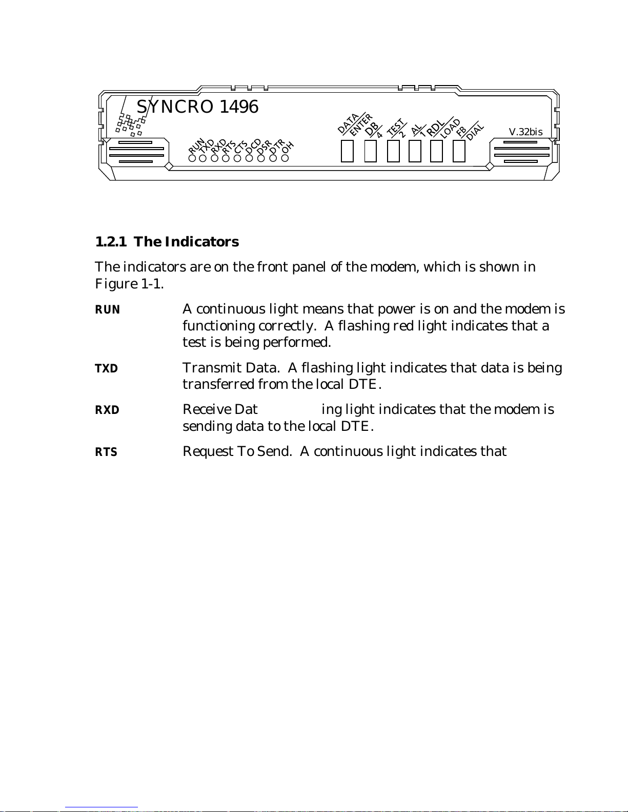
1.2.1 The Indicators
The indicators are on the front panel of the modem, which is shown in
Figure 1-1.
RUN A continuous light means that power is on and the modem is
functioning correctly. A flashing red light indicates that a
test is being performed.
TXD Transmit Data. A flashing light indicates that data is being
transferred from the local DTE.
RXD Receive Data. A flashing light indicates that the modem is
sending data to the local DTE.
RTS Request To Send. A continuous light indicates that the local
DTE is ready to send data. In full-duplex mode this is
normally lit at all times, but in half-duplex mode, only when
data is ready to be transmitted.
CTS Clear To Send. A continuous light indicates that the modem
is ready to transmit data to a remote modem. In full-duplex
mode this is normally lit at all times, but in half-duplex
mode, lights shortly after the
RTS indicator.
DCD Data Carrier Detect. Lit to indicate recognition of a carrier
signal from the remote modem. In full-duplex mode this is
normally lit at all times, but in half-duplex mode, only when
the remote modem has control for transmitting.
DSR Data Set Ready. Lit to indicate that the modem has control
of the line and is in data transmit mode. During a self-test
with signal injection, indicates errors.
X450-310851 Issue 2 1-5 Rev.0
Page 16
DTR Data Terminal Ready. Lit to indicate that the local DTE is
ready to begin communications.
OH Off Hook. Lit when the modem has connected to the
telephone line.
1.2.2 The Controls
The controls are on the front of the modem, which is shown in Figure 1-1.
The names above the line are for on-line operation of the modem. The
names below the line are for configuration loading, or dialling on the
PSTN. The left-hand button is a non-latching switch. The other five have
a latching action.
aaaaaaaaaaaaaaaaaaaaaaaaaaaaaaaaaaaaaaaaaaaaaaaaaaaaaaaaaaaaaaaaaaaaaaaaaaaaaaaaaaaaaaaaaaaaaaaaaaaaaaaaaaaaaaaaaaaaaaaaaaa
a
a
aaaaaaaaaaaaaaaaaaaaaaaaaaaaaaaaaaaaaaaaaaaaaaaaaaaaaaaaaaaaaaaaaaaaaaaaaaaaaaaaaaaaaaaaaaaaaaaaaaaaaaaaaaaaaaaaaaaaaaaaa
a
a
a
aaaaaaaaaaaaaaaaaaaaaaaaaaaaaaaaaaaaaaaaaaaaaaaaaaaaaaaaaaaaaaaaaaaaaaaaaaaaaaaaaaaaaaaaaaaaaaaaaaaaaaaaaaaaaaaaaaaaaaaaa
a
a
a
aaaaaaaaaaaaaaaaaaaaaaaaaaaaaaaaaaaaaaaaaaaaaaaaaaaaaaaaaaaaaaaaaaaaaaaaaaaaaaaaaaaaaaaaaaaaaaaaaaaaaaaaaaaaaaaaaaaaaaaaa
a
a
a
aaaaaaaaaaaaaaaaaaaaaaaaaaaaaaaaaaaaaaaaaaaaaaaaaaaaaaaaaaaaaaaaaaaaaaaaaaaaaaaaaaaaaaaaaaaaaaaaaaaaaaaaaaaaaaaaaaaaaaaaa
a
a
a
aaaaaaaaaaaaaaaaaaaaaaaaaaaaaaaaaaaaaaaaaaaaaaaaaaaaaaaaaaaaaaaaaaaaaaaaaaaaaaaaaaaaaaaaaaaaaaaaaaaaaaaaaaaaaaaaaaaaaaaaa
a
a
a
aaaaaaaaaaaaaaaaaaaaaaaaaaaaaaaaaaaaaaaaaaaaaaaaaaaaaaaaaaaaaaaaaaaaaaaaaaaaaaaaaaaaaaaaaaaaaaaaaaaaaaaaaaaaaaaaaaaaaaaaa
a
a
a
aaaaaaaaaaaaaaaaaaaaaaaaaaaaaaaaaaaaaaaaaaaaaaaaaaaaaaaaaaaaaaaaaaaaaaaaaaaaaaaaaaaaaaaaaaaaaaaaaaaaaaaaaaaaaaaaaaaaaaaaa
a
a
a
aaaaaaaaaaaaaaaaaaaaaaaaaaaaaaaaaaaaaaaaaaaaaaaaaaaaaaaaaaaaaaaaaaaaaaaaaaaaaaaaaaaaaaaaaaaaaaaaaaaaaaaaaaaaaaaaaaaaaaaaa
a
a
a
aaaaaaaaaaaaaaaaaaaaaaaaaaaaaaaaaaaaaaaaaaaaaaaaaaaaaaaaaaaaaaaaaaaaaaaaaaaaaaaaaaaaaaaaaaaaaaaaaaaaaaaaaaaaaaaaaaaaaaaaa
a
a
a
aaaaaaaaaaaaaaaaaaaaaaaaaaaaaaaaaaaaaaaaaaaaaaaaaaaaaaaaaaaaaaaaaaaaaaaaaaaaaaaaaaaaaaaaaaaaaaaaaaaaaaaaaaaaaaaaaaaaaaaaa
a
a
a
aaaaaaaaaaaaaaaaaaaaaaaaaaaaaaaaaaaaaaaaaaaaaaaaaaaaaaaaaaaaaaaaaaaaaaaaaaaaaaaaaaaaaaaaaaaaaaaaaaaaaaaaaaaaaaaaaaaaaaaaa
a
a
a
aaaaaaaaaaaaaaaaaaaaaaaaaaaaaaaaaaaaaaaaaaaaaaaaaaaaaaaaaaaaaaaaaaaaaaaaaaaaaaaaaaaaaaaaaaaaaaaaaaaaaaaaaaaaaaaaaaaaaaaaa
a
a
a
aaaaaaaaaaaaaaaaaaaaaaaaaaaaaaaaaaaaaaaaaaaaaaaaaaaaaaaaaaaaaaaaaaaaaaaaaaaaaaaaaaaaaaaaaaaaaaaaaaaaaaaaaaaaaaaaaaaaaaaaa
a
a
a
aaaaaaaaaaaaaaaaaaaaaaaaaaaaaaaaaaaaaaaaaaaaaaaaaaaaaaaaaaaaaaaaaaaaaaaaaaaaaaaaaaaaaaaaaaaaaaaaaaaaaaaaaaaaaaaaaaaaaaaaa
a
a
a
aaaaaaaaaaaaaaaaaaaaaaaaaaaaaaaaaaaaaaaaaaaaaaaaaaaaaaaaaaaaaaaaaaaaaaaaaaaaaaaaaaaaaaaaaaaaaaaaaaaaaaaaaaaaaaaaaaaaaaaaa
a
a
a
aaaaaaaaaaaaaaaaaaaaaaaaaaaaaaaaaaaaaaaaaaaaaaaaaaaaaaaaaaaaaaaaaaaaaaaaaaaaaaaaaaaaaaaaaaaaaaaaaaaaaaaaaaaaaaaaaaaaaaaaa
a
a
a
aaaaaaaaaaaaaaaaaaaaaaaaaaaaaaaaaaaaaaaaaaaaaaaaaaaaaaaaaaaaaaaaaaaaaaaaaaaaaaaaaaaaaaaaaaaaaaaaaaaaaaaaaaaaaaaaaaaaaaaaa
a
a
a
aaaaaaaaaaaaaaaaaaaaaaaaaaaaaaaaaaaaaaaaaaaaaaaaaaaaaaaaaaaaaaaaaaaaaaaaaaaaaaaaaaaaaaaaaaaaaaaaaaaaaaaaaaaaaaaaaaaaaaaaa
a
a
a
aaaaaaaaaaaaaaaaaaaaaaaaaaaaaaaaaaaaaaaaaaaaaaaaaaaaaaaaaaaaaaaaaaaaaaaaaaaaaaaaaaaaaaaaaaaaaaaaaaaaaaaaaaaaaaaaaaaaaaaaa
a
a
a
aaaaaaaaaaaaaaaaaaaaaaaaaaaaaaaaaaaaaaaaaaaaaaaaaaaaaaaaaaaaaaaaaaaaaaaaaaaaaaaaaaaaaaaaaaaaaaaaaaaaaaaaaaaaaaaaaaaaaaaaa
a
a
a
aaaaaaaaaaaaaaaaaaaaaaaaaaaaaaaaaaaaaaaaaaaaaaaaaaaaaaaaaaaaaaaaaaaaaaaaaaaaaaaaaaaaaaaaaaaaaaaaaaaaaaaaaaaaaaaaaaaaaaaaa
a
a
a
aaaaaaaaaaaaaaaaaaaaaaaaaaaaaaaaaaaaaaaaaaaaaaaaaaaaaaaaaaaaaaaaaaaaaaaaaaaaaaaaaaaaaaaaaaaaaaaaaaaaaaaaaaaaaaaaaaaaaaaaa
a
a
a
aaaaaaaaaaaaaaaaaaaaaaaaaaaaaaaaaaaaaaaaaaaaaaaaaaaaaaaaaaaaaaaaaaaaaaaaaaaaaaaaaaaaaaaaaaaaaaaaaaaaaaaaaaaaaaaaaaaaaaaaa
a
a
a
aaaaaaaaaaaaaaaaaaaaaaaaaaaaaaaaaaaaaaaaaaaaaaaaaaaaaaaaaaaaaaaaaaaaaaaaaaaaaaaaaaaaaaaaaaaaaaaaaaaaaaaaaaaaaaaaaaaaaaaaa
a
a
a
aaaaaaaaaaaaaaaaaaaaaaaaaaaaaaaaaaaaaaaaaaaaaaaaaaaaaaaaaaaaaaaaaaaaaaaaaaaaaaaaaaaaaaaaaaaaaaaaaaaaaaaaaaaaaaaaaaaaaaaaa
a
a
a
aaaaaaaaaaaaaaaaaaaaaaaaaaaaaaaaaaaaaaaaaaaaaaaaaaaaaaaaaaaaaaaaaaaaaaaaaaaaaaaaaaaaaaaaaaaaaaaaaaaaaaaaaaaaaaaaaaaaaaaaa
a
a
a
aaaaaaaaaaaaaaaaaaaaaaaaaaaaaaaaaaaaaaaaaaaaaaaaaaaaaaaaaaaaaaaaaaaaaaaaaaaaaaaaaaaaaaaaaaaaaaaaaaaaaaaaaaaaaaaaaaaaaaaaa
a
a
a
aaaaaaaaaaaaaaaaaaaaaaaaaaaaaaaaaaaaaaaaaaaaaaaaaaaaaaaaaaaaaaaaaaaaaaaaaaaaaaaaaaaaaaaaaaaaaaaaaaaaaaaaaaaaaaaaaaaaaaaaa
a
a
a
aaaaaaaaaaaaaaaaaaaaaaaaaaaaaaaaaaaaaaaaaaaaaaaaaaaaaaaaaaaaaaaaaaaaaaaaaaaaaaaaaaaaaaaaaaaaaaaaaaaaaaaaaaaaaaaaaaaaaaaaa
a
a
a
aaaaaaaaaaaaaaaaaaaaaaaaaaaaaaaaaaaaaaaaaaaaaaaaaaaaaaaaaaaaaaaaaaaaaaaaaaaaaaaaaaaaaaaaaaaaaaaaaaaaaaaaaaaaaaaaaaaaaaaaa
a
a
a
aaaaaaaaaaaaaaaaaaaaaaaaaaaaaaaaaaaaaaaaaaaaaaaaaaaaaaaaaaaaaaaaaaaaaaaaaaaaaaaaaaaaaaaaaaaaaaaaaaaaaaaaaaaaaaaaaaaaaaaaa
a
a
a
aaaaaaaaaaaaaaaaaaaaaaaaaaaaaaaaaaaaaaaaaaaaaaaaaaaaaaaaaaaaaaaaaaaaaaaaaaaaaaaaaaaaaaaaaaaaaaaaaaaaaaaaaaaaaaaaaaaaaaaaa
a
a
a
aaaaaaaaaaaaaaaaaaaaaaaaaaaaaaaaaaaaaaaaaaaaaaaaaaaaaaaaaaaaaaaaaaaaaaaaaaaaaaaaaaaaaaaaaaaaaaaaaaaaaaaaaaaaaaaaaaaaaaaaa
a
a
a
aaaaaaaaaaaaaaaaaaaaaaaaaaaaaaaaaaaaaaaaaaaaaaaaaaaaaaaaaaaaaaaaaaaaaaaaaaaaaaaaaaaaaaaaaaaaaaaaaaaaaaaaaaaaaaaaaaaaaaaaa
a
a
a
aaaaaaaaaaaaaaaaaaaaaaaaaaaaaaaaaaaaaaaaaaaaaaaaaaaaaaaaaaaaaaaaaaaaaaaaaaaaaaaaaaaaaaaaaaaaaaaaaaaaaaaaaaaaaaaaaaaaaaaaa
a
a
a
aaaaaaaaaaaaaaaaaaaaaaaaaaaaaaaaaaaaaaaaaaaaaaaaaaaaaaaaaaaaaaaaaaaaaaaaaaaaaaaaaaaaaaaaaaaaaaaaaaaaaaaaaaaaaaaaaaaaaaaaa
a
a
a
aaaaaaaaaaaaaaaaaaaaaaaaaaaaaaaaaaaaaaaaaaaaaaaaaaaaaaaaaaaaaaaaaaaaaaaaaaaaaaaaaaaaaaaaaaaaaaaaaaaaaaaaaaaaaaaaaaaaaaaaa
a
a
a
aaaaaaaaaaaaaaaaaaaaaaaaaaaaaaaaaaaaaaaaaaaaaaaaaaaaaaaaaaaaaaaaaaaaaaaaaaaaaaaaaaaaaaaaaaaaaaaaaaaaaaaaaaaaaaaaaaaaaaaaa
a
a
a
aaaaaaaaaaaaaaaaaaaaaaaaaaaaaaaaaaaaaaaaaaaaaaaaaaaaaaaaaaaaaaaaaaaaaaaaaaaaaaaaaaaaaaaaaaaaaaaaaaaaaaaaaaaaaaaaaaaaaaaaa
a
a
a
aaaaaaaaaaaaaaaaaaaaaaaaaaaaaaaaaaaaaaaaaaaaaaaaaaaaaaaaaaaaaaaaaaaaaaaaaaaaaaaaaaaaaaaaaaaaaaaaaaaaaaaaaaaaaaaaaaaaaaaaa
a
a
a
aaaaaaaaaaaaaaaaaaaaaaaaaaaaaaaaaaaaaaaaaaaaaaaaaaaaaaaaaaaaaaaaaaaaaaaaaaaaaaaaaaaaaaaaaaaaaaaaaaaaaaaaaaaaaaaaaaaaaaaaa
a
a
a
aaaaaaaaaaaaaaaaaaaaaaaaaaaaaaaaaaaaaaaaaaaaaaaaaaaaaaaaaaaaaaaaaaaaaaaaaaaaaaaaaaaaaaaaaaaaaaaaaaaaaaaaaaaaaaaaaaaaaaaaa
a
a
a
aaaaaaaaaaaaaaaaaaaaaaaaaaaaaaaaaaaaaaaaaaaaaaaaaaaaaaaaaaaaaaaaaaaaaaaaaaaaaaaaaaaaaaaaaaaaaaaaaaaaaaaaaaaaaaaaaaaaaaaaa
a
a
a
aaaaaaaaaaaaaaaaaaaaaaaaaaaaaaaaaaaaaaaaaaaaaaaaaaaaaaaaaaaaaaaaaaaaaaaaaaaaaaaaaaaaaaaaaaaaaaaaaaaaaaaaaaaaaaaaaaaaaaaaa
a
a
a
aaaaaaaaaaaaaaaaaaaaaaaaaaaaaaaaaaaaaaaaaaaaaaaaaaaaaaaaaaaaaaaaaaaaaaaaaaaaaaaaaaaaaaaaaaaaaaaaaaaaaaaaaaaaaaaaaaaaaaaaa
a
a
a
aaaaaaaaaaaaaaaaaaaaaaaaaaaaaaaaaaaaaaaaaaaaaaaaaaaaaaaaaaaaaaaaaaaaaaaaaaaaaaaaaaaaaaaaaaaaaaaaaaaaaaaaaaaaaaaaaaaaaaaaa
a
a
a
aaaaaaaaaaaaaaaaaaaaaaaaaaaaaaaaaaaaaaaaaaaaaaaaaaaaaaaaaaaaaaaaaaaaaaaaaaaaaaaaaaaaaaaaaaaaaaaaaaaaaaaaaaaaaaaaaaaaaaaaa
a
a
a
aaaaaaaaaaaaaaaaaaaaaaaaaaaaaaaaaaaaaaaaaaaaaaaaaaaaaaaaaaaaaaaaaaaaaaaaaaaaaaaaaaaaaaaaaaaaaaaaaaaaaaaaaaaaaaaaaaaaaaaaa
a
a
a
aaaaaaaaaaaaaaaaaaaaaaaaaaaaaaaaaaaaaaaaaaaaaaaaaaaaaaaaaaaaaaaaaaaaaaaaaaaaaaaaaaaaaaaaaaaaaaaaaaaaaaaaaaaaaaaaaaaaaaaaa
a
a
a
aaaaaaaaaaaaaaaaaaaaaaaaaaaaaaaaaaaaaaaaaaaaaaaaaaaaaaaaaaaaaaaaaaaaaaaaaaaaaaaaaaaaaaaaaaaaaaaaaaaaaaaaaaaaaaaaaaaaaaaaa
a
a
a
aaaaaaaaaaaaaaaaaaaaaaaaaaaaaaaaaaaaaaaaaaaaaaaaaaaaaaaaaaaaaaaaaaaaaaaaaaaaaaaaaaaaaaaaaaaaaaaaaaaaaaaaaaaaaaaaaaaaaaaaa
a
a
a
aaaaaaaaaaaaaaaaaaaaaaaaaaaaaaaaaaaaaaaaaaaaaaaaaaaaaaaaaaaaaaaaaaaaaaaaaaaaaaaaaaaaaaaaaaaaaaaaaaaaaaaaaaaaaaaaaaaaaaaaa
a
a
a
aaaaaaaaaaaaaaaaaaaaaaaaaaaaaaaaaaaaaaaaaaaaaaaaaaaaaaaaaaaaaaaaaaaaaaaaaaaaaaaaaaaaaaaaaaaaaaaaaaaaaaaaaaaaaaaaaaaaaaaaa
a
a
a
aaaaaaaaaaaaaaaaaaaaaaaaaaaaaaaaaaaaaaaaaaaaaaaaaaaaaaaaaaaaaaaaaaaaaaaaaaaaaaaaaaaaaaaaaaaaaaaaaaaaaaaaaaaaaaaaaaaaaaaaa
a
a
a
aaaaaaaaaaaaaaaaaaaaaaaaaaaaaaaaaaaaaaaaaaaaaaaaaaaaaaaaaaaaaaaaaaaaaaaaaaaaaaaaaaaaaaaaaaaaaaaaaaaaaaaaaaaaaaaaaaaaaaaaa
a
a
a
aaaaaaaaaaaaaaaaaaaaaaaaaaaaaaaaaaaaaaaaaaaaaaaaaaaaaaaaaaaaaaaaaaaaaaaaaaaaaaaaaaaaaaaaaaaaaaaaaaaaaaaaaaaaaaaaaaaaaaaaa
a
a
a
aaaaaaaaaaaaaaaaaaaaaaaaaaaaaaaaaaaaaaaaaaaaaaaaaaaaaaaaaaaaaaaaaaaaaaaaaaaaaaaaaaaaaaaaaaaaaaaaaaaaaaaaaaaaaaaaaaaaaaaaa
a
a
a
aaaaaaaaaaaaaaaaaaaaaaaaaaaaaaaaaaaaaaaaaaaaaaaaaaaaaaaaaaaaaaaaaaaaaaaaaaaaaaaaaaaaaaaaaaaaaaaaaaaaaaaaaaaaaaaaaaaaaaaaa
a
a
a
aaaaaaaaaaaaaaaaaaaaaaaaaaaaaaaaaaaaaaaaaaaaaaaaaaaaaaaaaaaaaaaaaaaaaaaaaaaaaaaaaaaaaaaaaaaaaaaaaaaaaaaaaaaaaaaaaaaaaaaaa
a
a
a
aaaaaaaaaaaaaaaaaaaaaaaaaaaaaaaaaaaaaaaaaaaaaaaaaaaaaaaaaaaaaaaaaaaaaaaaaaaaaaaaaaaaaaaaaaaaaaaaaaaaaaaaaaaaaaaaaaaaaaaaa
a
a
a
aaaaaaaaaaaaaaaaaaaaaaaaaaaaaaaaaaaaaaaaaaaaaaaaaaaaaaaaaaaaaaaaaaaaaaaaaaaaaaaaaaaaaaaaaaaaaaaaaaaaaaaaaaaaaaaaaaaaaaaaa
a
a
a
aaaaaaaaaaaaaaaaaaaaaaaaaaaaaaaaaaaaaaaaaaaaaaaaaaaaaaaaaaaaaaaaaaaaaaaaaaaaaaaaaaaaaaaaaaaaaaaaaaaaaaaaaaaaaaaaaaaaaaaaa
a
a
a
aaaaaaaaaaaaaaaaaaaaaaaaaaaaaaaaaaaaaaaaaaaaaaaaaaaaaaaaaaaaaaaaaaaaaaaaaaaaaaaaaaaaaaaaaaaaaaaaaaaaaaaaaaaaaaaaaaaaaaaaa
a
a
a
aaaaaaaaaaaaaaaaaaaaaaaaaaaaaaaaaaaaaaaaaaaaaaaaaaaaaaaaaaaaaaaaaaaaaaaaaaaaaaaaaaaaaaaaaaaaaaaaaaaaaaaaaaaaaaaaaaaaaaaaa
a
a
a
aaaaaaaaaaaaaaaaaaaaaaaaaaaaaaaaaaaaaaaaaaaaaaaaaaaaaaaaaaaaaaaaaaaaaaaaaaaaaaaaaaaaaaaaaaaaaaaaaaaaaaaaaaaaaaaaaaaaaaaaa
a
a
a
aaaaaaaaaaaaaaaaaaaaaaaaaaaaaaaaaaaaaaaaaaaaaaaaaaaaaaaaaaaaaaaaaaaaaaaaaaaaaaaaaaaaaaaaaaaaaaaaaaaaaaaaaaaaaaaaaaaaaaaaa
a
a
a
aaaaaaaaaaaaaaaaaaaaaaaaaaaaaaaaaaaaaaaaaaaaaaaaaaaaaaaaaaaaaaaaaaaaaaaaaaaaaaaaaaaaaaaaaaaaaaaaaaaaaaaaaaaaaaaaaaaaaaaaa
a
a
a
aaaaaaaaaaaaaaaaaaaaaaaaaaaaaaaaaaaaaaaaaaaaaaaaaaaaaaaaaaaaaaaaaaaaaaaaaaaaaaaaaaaaaaaaaaaaaaaaaaaaaaaaaaaaaaaaaaaaaaaaa
a
a
a
aaaaaaaaaaaaaaaaaaaaaaaaaaaaaaaaaaaaaaaaaaaaaaaaaaaaaaaaaaaaaaaaaaaaaaaaaaaaaaaaaaaaaaaaaaaaaaaaaaaaaaaaaaaaaaaaaaaaaaaaa
a
a
a
aaaaaaaaaaaaaaaaaaaaaaaaaaaaaaaaaaaaaaaaaaaaaaaaaaaaaaaaaaaaaaaaaaaaaaaaaaaaaaaaaaaaaaaaaaaaaaaaaaaaaaaaaaaaaaaaaaaaaaaaa
a
a
a
aaaaaaaaaaaaaaaaaaaaaaaaaaaaaaaaaaaaaaaaaaaaaaaaaaaaaaaaaaaaaaaaaaaaaaaaaaaaaaaaaaaaaaaaaaaaaaaaaaaaaaaaaaaaaaaaaaaaaaaaa
a
a
a
aaaaaaaaaaaaaaaaaaaaaaaaaaaaaaaaaaaaaaaaaaaaaaaaaaaaaaaaaaaaaaaaaaaaaaaaaaaaaaaaaaaaaaaaaaaaaaaaaaaaaaaaaaaaaaaaaaaaaaaaa
a
a
a
aaaaaaaaaaaaaaaaaaaaaaaaaaaaaaaaaaaaaaaaaaaaaaaaaaaaaaaaaaaaaaaaaaaaaaaaaaaaaaaaaaaaaaaaaaaaaaaaaaaaaaaaaaaaaaaaaaaaaaaaa
a
a
a
aaaaaaaaaaaaaaaaaaaaaaaaaaaaaaaaaaaaaaaaaaaaaaaaaaaaaaaaaaaaaaaaaaaaaaaaaaaaaaaaaaaaaaaaaaaaaaaaaaaaaaaaaaaaaaaaaaaaaaaaa
a
a
a
aaaaaaaaaaaaaaaaaaaaaaaaaaaaaaaaaaaaaaaaaaaaaaaaaaaaaaaaaaaaaaaaaaaaaaaaaaaaaaaaaaaaaaaaaaaaaaaaaaaaaaaaaaaaaaaaaaaaaaaaa
a
a
a
aaaaaaaaaaaaaaaaaaaaaaaaaaaaaaaaaaaaaaaaaaaaaaaaaaaaaaaaaaaaaaaaaaaaaaaaaaaaaaaaaaaaaaaaaaaaaaaaaaaaaaaaaaaaaaaaaaaaaaaaa
a
a
a
aaaaaaaaaaaaaaaaaaaaaaaaaaaaaaaaaaaaaaaaaaaaaaaaaaaaaaaaaaaaaaaaaaaaaaaaaaaaaaaaaaaaaaaaaaaaaaaaaaaaaaaaaaaaaaaaaaaaaaaaa
a
a
a
aaaaaaaaaaaaaaaaaaaaaaaaaaaaaaaaaaaaaaaaaaaaaaaaaaaaaaaaaaaaaaaaaaaaaaaaaaaaaaaaaaaaaaaaaaaaaaaaaaaaaaaaaaaaaaaaaaaaaaaaa
a
a
a
aaaaaaaaaaaaaaaaaaaaaaaaaaaaaaaaaaaaaaaaaaaaaaaaaaaaaaaaaaaaaaaaaaaaaaaaaaaaaaaaaaaaaaaaaaaaaaaaaaaaaaaaaaaaaaaaaaaaaaaaa
a
a
a
aaaaaaaaaaaaaaaaaaaaaaaaaaaaaaaaaaaaaaaaaaaaaaaaaaaaaaaaaaaaaaaaaaaaaaaaaaaaaaaaaaaaaaaaaaaaaaaaaaaaaaaaaaaaaaaaaaaaaaaaa
a
a
a
aaaaaaaaaaaaaaaaaaaaaaaaaaaaaaaaaaaaaaaaaaaaaaaaaaaaaaaaaaaaaaaaaaaaaaaaaaaaaaaaaaaaaaaaaaaaaaaaaaaaaaaaaaaaaaaaaaaaaaaaa
a
a
a
aaaaaaaaaaaaaaaaaaaaaaaaaaaaaaaaaaaaaaaaaaaaaaaaaaaaaaaaaaaaaaaaaaaaaaaaaaaaaaaaaaaaaaaaaaaaaaaaaaaaaaaaaaaaaaaaaaaaaaaaa
a
a
a
aaaaaaaaaaaaaaaaaaaaaaaaaaaaaaaaaaaaaaaaaaaaaaaaaaaaaaaaaaaaaaaaaaaaaaaaaaaaaaaaaaaaaaaaaaaaaaaaaaaaaaaaaaaaaaaaaaaaaaaaa
a
a
a
aaaaaaaaaaaaaaaaaaaaaaaaaaaaaaaaaaaaaaaaaaaaaaaaaaaaaaaaaaaaaaaaaaaaaaaaaaaaaaaaaaaaaaaaaaaaaaaaaaaaaaaaaaaaaaaaaaaaaaaaa
a
a
a
aaaaaaaaaaaaaaaaaaaaaaaaaaaaaaaaaaaaaaaaaaaaaaaaaaaaaaaaaaaaaaaaaaaaaaaaaaaaaaaaaaaaaaaaaaaaaaaaaaaaaaaaaaaaaaaaaaaaaaaaa
a
a
a
aaaaaaaaaaaaaaaaaaaaaaaaaaaaaaaaaaaaaaaaaaaaaaaaaaaaaaaaaaaaaaaaaaaaaaaaaaaaaaaaaaaaaaaaaaaaaaaaaaaaaaaaaaaaaaaaaaaaaaaaa
a
a
a
aaaaaaaaaaaaaaaaaaaaaaaaaaaaaaaaaaaaaaaaaaaaaaaaaaaaaaaaaaaaaaaaaaaaaaaaaaaaaaaaaaaaaaaaaaaaaaaaaaaaaaaaaaaaaaaaaaaaaaaaa
a
a
a
aaaaaaaaaaaaaaaaaaaaaaaaaaaaaaaaaaaaaaaaaaaaaaaaaaaaaaaaaaaaaaaaaaaaaaaaaaaaaaaaaaaaaaaaaaaaaaaaaaaaaaaaaaaaaaaaaaaaaaaaa
a
a
a
aaaaaaaaaaaaaaaaaaaaaaaaaaaaaaaaaaaaaaaaaaaaaaaaaaaaaaaaaaaaaaaaaaaaaaaaaaaaaaaaaaaaaaaaaaaaaaaaaaaaaaaaaaaaaaaaaaaaaaaaa
a
a
a
aaaaaaaaaaaaaaaaaaaaaaaaaaaaaaaaaaaaaaaaaaaaaaaaaaaaaaaaaaaaaaaaaaaaaaaaaaaaaaaaaaaaaaaaaaaaaaaaaaaaaaaaaaaaaaaaaaaaaaaaa
a
a
a
aaaaaaaaaaaaaaaaaaaaaaaaaaaaaaaaaaaaaaaaaaaaaaaaaaaaaaaaaaaaaaaaaaaaaaaaaaaaaaaaaaaaaaaaaaaaaaaaaaaaaaaaaaaaaaaaaaaaaaaaa
a
a
a
aaaaaaaaaaaaaaaaaaaaaaaaaaaaaaaaaaaaaaaaaaaaaaaaaaaaaaaaaaaaaaaaaaaaaaaaaaaaaaaaaaaaaaaaaaaaaaaaaaaaaaaaaaaaaaaaaaaaaaaaa
a
a
a
aaaaaaaaaaaaaaaaaaaaaaaaaaaaaaaaaaaaaaaaaaaaaaaaaaaaaaaaaaaaaaaaaaaaaaaaaaaaaaaaaaaaaaaaaaaaaaaaaaaaaaaaaaaaaaaaaaaaaaaaa
a
a
a
aaaaaaaaaaaaaaaaaaaaaaaaaaaaaaaaaaaaaaaaaaaaaaaaaaaaaaaaaaaaaaaaaaaaaaaaaaaaaaaaaaaaaaaaaaaaaaaaaaaaaaaaaaaaaaaaaaaaaaaaa
a
a
a
aaaaaaaaaaaaaaaaaaaaaaaaaaaaaaaaaaaaaaaaaaaaaaaaaaaaaaaaaaaaaaaaaaaaaaaaaaaaaaaaaaaaaaaaaaaaaaaaaaaaaaaaaaaaaaaaaaaaaaaaa
a
a
a
aaaaaaaaaaaaaaaaaaaaaaaaaaaaaaaaaaaaaaaaaaaaaaaaaaaaaaaaaaaaaaaaaaaaaaaaaaaaaaaaaaaaaaaaaaaaaaaaaaaaaaaaaaaaaaaaaaaaaaaaa
a
a
a
aaaaaaaaaaaaaaaaaaaaaaaaaaaaaaaaaaaaaaaaaaaaaaaaaaaaaaaaaaaaaaaaaaaaaaaaaaaaaaaaaaaaaaaaaaaaaaaaaaaaaaaaaaaaaaaaaaaaaaaaa
a
a
a
aaaaaaaaaaaaaaaaaaaaaaaaaaaaaaaaaaaaaaaaaaaaaaaaaaaaaaaaaaaaaaaaaaaaaaaaaaaaaaaaaaaaaaaaaaaaaaaaaaaaaaaaaaaaaaaaaaaaaaaaa
a
a
a
aaaaaaaaaaaaaaaaaaaaaaaaaaaaaaaaaaaaaaaaaaaaaaaaaaaaaaaaaaaaaaaaaaaaaaaaaaaaaaaaaaaaaaaaaaaaaaaaaaaaaaaaaaaaaaaaaaaaaaaaa
a
a
a
aaaaaaaaaaaaaaaaaaaaaaaaaaaaaaaaaaaaaaaaaaaaaaaaaaaaaaaaaaaaaaaaaaaaaaaaaaaaaaaaaaaaaaaaaaaaaaaaaaaaaaaaaaaaaaaaaaaaaaaaa
a
a
a
aaaaaaaaaaaaaaaaaaaaaaaaaaaaaaaaaaaaaaaaaaaaaaaaaaaaaaaaaaaaaaaaaaaaaaaaaaaaaaaaaaaaaaaaaaaaaaaaaaaaaaaaaaaaaaaaaaaaaaaaa
a
a
a
aaaaaaaaaaaaaaaaaaaaaaaaaaaaaaaaaaaaaaaaaaaaaaaaaaaaaaaaaaaaaaaaaaaaaaaaaaaaaaaaaaaaaaaaaaaaaaaaaaaaaaaaaaaaaaaaaaaaaaaaa
a
a
a
aaaaaaaaaaaaaaaaaaaaaaaaaaaaaaaaaaaaaaaaaaaaaaaaaaaaaaaaaaaaaaaaaaaaaaaaaaaaaaaaaaaaaaaaaaaaaaaaaaaaaaaaaaaaaaaaaaaaaaaaa
a
a
a
aaaaaaaaaaaaaaaaaaaaaaaaaaaaaaaaaaaaaaaaaaaaaaaaaaaaaaaaaaaaaaaaaaaaaaaaaaaaaaaaaaaaaaaaaaaaaaaaaaaaaaaaaaaaaaaaaaaaaaaaa
a
a
a
aaaaaaaaaaaaaaaaaaaaaaaaaaaaaaaaaaaaaaaaaaaaaaaaaaaaaaaaaaaaaaaaaaaaaaaaaaaaaaaaaaaaaaaaaaaaaaaaaaaaaaaaaaaaaaaaaaaaaaaaa
a
a
a
aaaaaaaaaaaaaaaaaaaaaaaaaaaaaaaaaaaaaaaaaaaaaaaaaaaaaaaaaaaaaaaaaaaaaaaaaaaaaaaaaaaaaaaaaaaaaaaaaaaaaaaaaaaaaaaaaaaaaaaaa
a
a
a
aaaaaaaaaaaaaaaaaaaaaaaaaaaaaaaaaaaaaaaaaaaaaaaaaaaaaaaaaaaaaaaaaaaaaaaaaaaaaaaaaaaaaaaaaaaaaaaaaaaaaaaaaaaaaaaaaaaaaaaaa
a
a
a
aaaaaaaaaaaaaaaaaaaaaaaaaaaaaaaaaaaaaaaaaaaaaaaaaaaaaaaaaaaaaaaaaaaaaaaaaaaaaaaaaaaaaaaaaaaaaaaaaaaaaaaaaaaaaaaaaaaaaaaaa
a
a
a
aaaaaaaaaaaaaaaaaaaaaaaaaaaaaaaaaaaaaaaaaaaaaaaaaaaaaaaaaaaaaaaaaaaaaaaaaaaaaaaaaaaaaaaaaaaaaaaaaaaaaaaaaaaaaaaaaaaaaaaaa
a
a
a
aaaaaaaaaaaaaaaaaaaaaaaaaaaaaaaaaaaaaaaaaaaaaaaaaaaaaaaaaaaaaaaaaaaaaaaaaaaaaaaaaaaaaaaaaaaaaaaaaaaaaaaaaaaaaaaaaaaaaaaaa
a
a
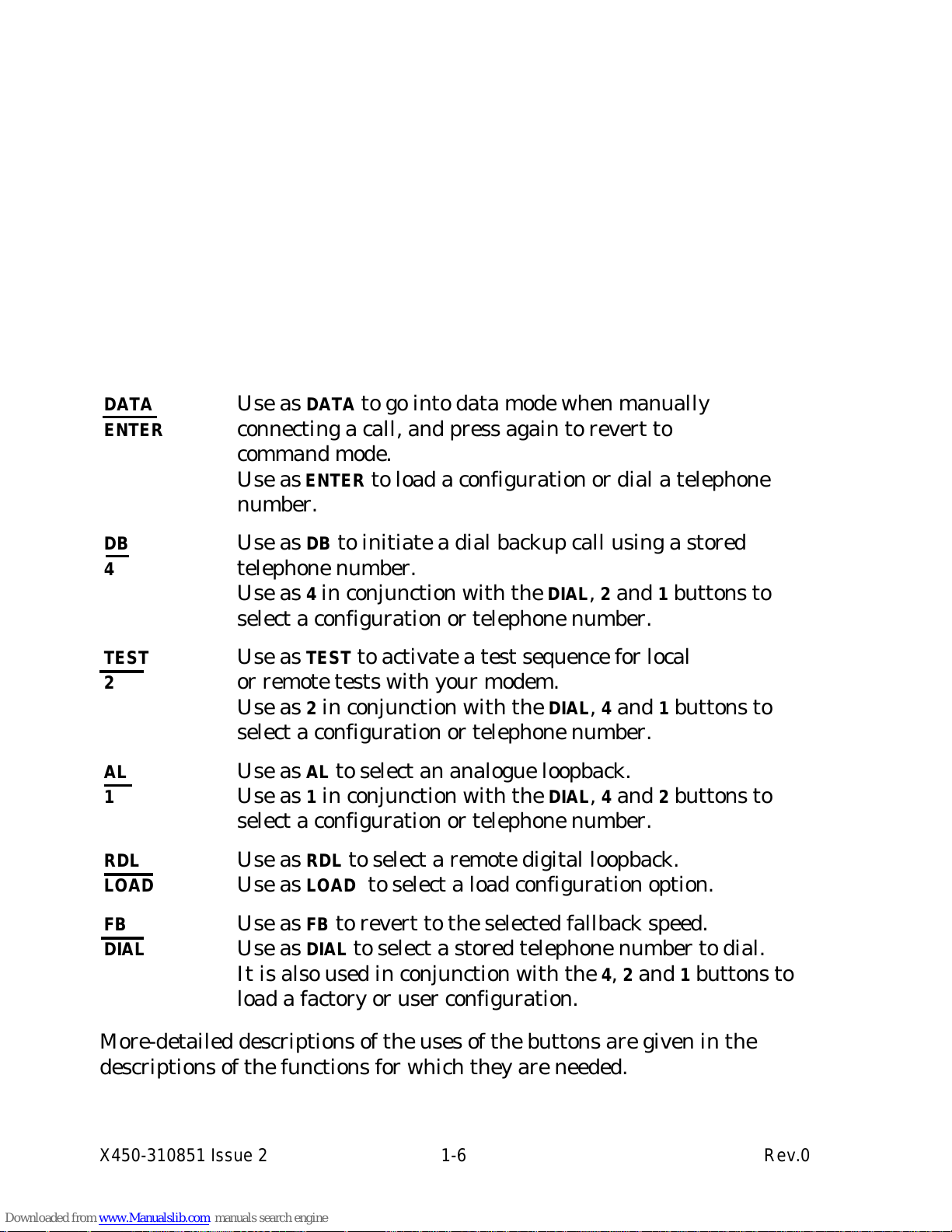
DATA Use as DATA to go into data mode when manually
ENTER connecting a call, and press again to revert to
command mode.
Use as
ENTER to load a configuration or dial a telephone
number.
DB Use as DB to initiate a dial backup call using a stored
4 telephone number.
Use as
4 in conjunction with the DIAL, 2 and 1 buttons to
select a configuration or telephone number.
TEST Use as TEST to activate a test sequence for local
2 or remote tests with your modem.
Use as
2 in conjunction with the DIAL, 4 and 1 buttons to
select a configuration or telephone number.
AL Use as AL to select an analogue loopback.
1 Use as 1 in conjunction with the DIAL, 4 and 2 buttons to
select a configuration or telephone number.
RDL Use as RDL to select a remote digital loopback.
LOAD Use as LOAD to select a load configuration option.
FB Use as FB to revert to the selected fallback speed.
DIAL Use as DIAL to select a stored telephone number to dial.
It is also used in conjunction with the
4, 2 and 1 buttons to
load a factory or user configuration.
More-detailed descriptions of the uses of the buttons are given in the
descriptions of the functions for which they are needed.
X450-310851 Issue 2 1-6 Rev.0
Page 17
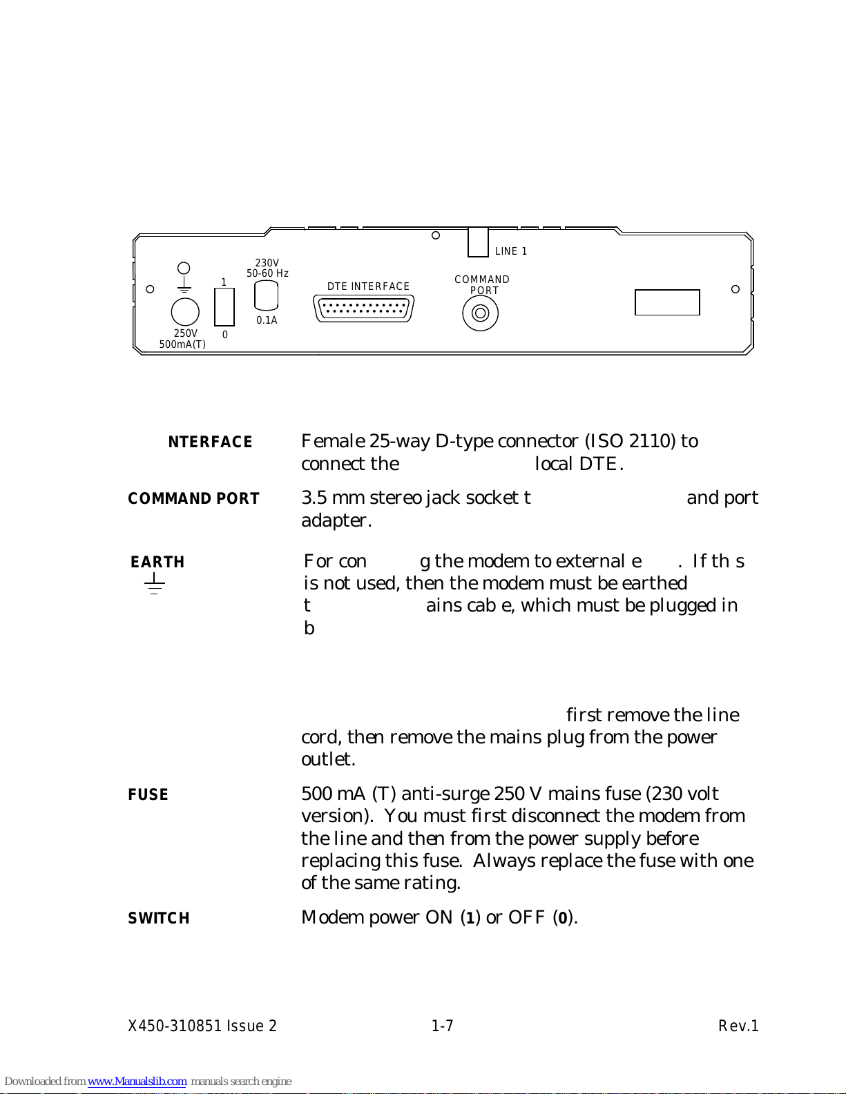
1.2.3 The Connections
The connections are made from the rear panel of the modem. The 230 volt
version is shown in Figure 1-2.
Pin assignments and suggested cable configurations are detailed in
Appendix B.
Figure 1-2 The Standalone Modem Rear Panel
aaaaaaaaaaaaa
a
aaaaaaaaaaa
a
a
aaaaaaaaaaa
a
a
aaaaaaaaaaa
a
COMMAND
PORT
aaaaaaaaaaaaaaa
a
a
aaaaaaaaaaaaa
a
a
aaaaaaaaaaaaa
a
DTE INTERFACE
aaaaaaaaa
a
a
aaaaaaa
a
a
a
aaaaaaa
a
a
a
aaaaaaa
a
a
250V
500mA(T)
aaaaaaa
a
aaaaa
a
a
aaaaa
a
LINE 1
aaaaa
a
aaa
a
a
aaa
a
a
aaa
a
0.1A
a
a
a
a
a
a
1
aaaaaaaaa
a
aaaaaaa
a
a
aaaaaaa
a
a
aaaaaaa
a
230V
50-60 Hz
a
a
a
a
a
a
0
aaaaaaa
a
aaaaa
a
a
aaaaa
a
LINE 3
DTE INTERFACE Female 25-way D-type connector (ISO 2110) to
connect the modem to your local DTE.
COMMAND PORT 3.5 mm stereo jack socket to accept the command port
adapter.
aaaaaaaaaaaaaaaaaaaaaaaaaaaaaaaaaaaaaaaaaaaaaaaaaaaaaaaaaaaaaaaaaaaaaaaaaaaaaaaaaaaaaaaaaaaaaaaaaaaaaaaaaaaaaaaaaaaaaaaaaaa
a
a
aaaaaaaaaaaaaaaaaaaaaaaaaaaaaaaaaaaaaaaaaaaaaaaaaaaaaaaaaaaaaaaaaaaaaaaaaaaaaaaaaaaaaaaaaaaaaaaaaaaaaaaaaaaaaaaaaaaaaaaaa
a
a
a
aaaaaaaaaaaaaaaaaaaaaaaaaaaaaaaaaaaaaaaaaaaaaaaaaaaaaaaaaaaaaaaaaaaaaaaaaaaaaaaaaaaaaaaaaaaaaaaaaaaaaaaaaaaaaaaaaaaaaaaaa
a
a
a
aaaaaaaaaaaaaaaaaaaaaaaaaaaaaaaaaaaaaaaaaaaaaaaaaaaaaaaaaaaaaaaaaaaaaaaaaaaaaaaaaaaaaaaaaaaaaaaaaaaaaaaaaaaaaaaaaaaaaaaaa
a
a
a
aaaaaaaaaaaaaaaaaaaaaaaaaaaaaaaaaaaaaaaaaaaaaaaaaaaaaaaaaaaaaaaaaaaaaaaaaaaaaaaaaaaaaaaaaaaaaaaaaaaaaaaaaaaaaaaaaaaaaaaaa
a
a
a
aaaaaaaaaaaaaaaaaaaaaaaaaaaaaaaaaaaaaaaaaaaaaaaaaaaaaaaaaaaaaaaaaaaaaaaaaaaaaaaaaaaaaaaaaaaaaaaaaaaaaaaaaaaaaaaaaaaaaaaaa
a
a
a
aaaaaaaaaaaaaaaaaaaaaaaaaaaaaaaaaaaaaaaaaaaaaaaaaaaaaaaaaaaaaaaaaaaaaaaaaaaaaaaaaaaaaaaaaaaaaaaaaaaaaaaaaaaaaaaaaaaaaaaaa
a
a
a
aaaaaaaaaaaaaaaaaaaaaaaaaaaaaaaaaaaaaaaaaaaaaaaaaaaaaaaaaaaaaaaaaaaaaaaaaaaaaaaaaaaaaaaaaaaaaaaaaaaaaaaaaaaaaaaaaaaaaaaaa
a
a
a
aaaaaaaaaaaaaaaaaaaaaaaaaaaaaaaaaaaaaaaaaaaaaaaaaaaaaaaaaaaaaaaaaaaaaaaaaaaaaaaaaaaaaaaaaaaaaaaaaaaaaaaaaaaaaaaaaaaaaaaaa
a
a
a
aaaaaaaaaaaaaaaaaaaaaaaaaaaaaaaaaaaaaaaaaaaaaaaaaaaaaaaaaaaaaaaaaaaaaaaaaaaaaaaaaaaaaaaaaaaaaaaaaaaaaaaaaaaaaaaaaaaaaaaaa
a
a
a
aaaaaaaaaaaaaaaaaaaaaaaaaaaaaaaaaaaaaaaaaaaaaaaaaaaaaaaaaaaaaaaaaaaaaaaaaaaaaaaaaaaaaaaaaaaaaaaaaaaaaaaaaaaaaaaaaaaaaaaaa
a
a
a
aaaaaaaaaaaaaaaaaaaaaaaaaaaaaaaaaaaaaaaaaaaaaaaaaaaaaaaaaaaaaaaaaaaaaaaaaaaaaaaaaaaaaaaaaaaaaaaaaaaaaaaaaaaaaaaaaaaaaaaaa
a
a
a
aaaaaaaaaaaaaaaaaaaaaaaaaaaaaaaaaaaaaaaaaaaaaaaaaaaaaaaaaaaaaaaaaaaaaaaaaaaaaaaaaaaaaaaaaaaaaaaaaaaaaaaaaaaaaaaaaaaaaaaaa
a
a
a
aaaaaaaaaaaaaaaaaaaaaaaaaaaaaaaaaaaaaaaaaaaaaaaaaaaaaaaaaaaaaaaaaaaaaaaaaaaaaaaaaaaaaaaaaaaaaaaaaaaaaaaaaaaaaaaaaaaaaaaaa
a
a
a
aaaaaaaaaaaaaaaaaaaaaaaaaaaaaaaaaaaaaaaaaaaaaaaaaaaaaaaaaaaaaaaaaaaaaaaaaaaaaaaaaaaaaaaaaaaaaaaaaaaaaaaaaaaaaaaaaaaaaaaaa
a
a
a
aaaaaaaaaaaaaaaaaaaaaaaaaaaaaaaaaaaaaaaaaaaaaaaaaaaaaaaaaaaaaaaaaaaaaaaaaaaaaaaaaaaaaaaaaaaaaaaaaaaaaaaaaaaaaaaaaaaaaaaaa
a
a
a
aaaaaaaaaaaaaaaaaaaaaaaaaaaaaaaaaaaaaaaaaaaaaaaaaaaaaaaaaaaaaaaaaaaaaaaaaaaaaaaaaaaaaaaaaaaaaaaaaaaaaaaaaaaaaaaaaaaaaaaaa
a
a
a
aaaaaaaaaaaaaaaaaaaaaaaaaaaaaaaaaaaaaaaaaaaaaaaaaaaaaaaaaaaaaaaaaaaaaaaaaaaaaaaaaaaaaaaaaaaaaaaaaaaaaaaaaaaaaaaaaaaaaaaaa
a
a
a
aaaaaaaaaaaaaaaaaaaaaaaaaaaaaaaaaaaaaaaaaaaaaaaaaaaaaaaaaaaaaaaaaaaaaaaaaaaaaaaaaaaaaaaaaaaaaaaaaaaaaaaaaaaaaaaaaaaaaaaaa
a
a
a
aaaaaaaaaaaaaaaaaaaaaaaaaaaaaaaaaaaaaaaaaaaaaaaaaaaaaaaaaaaaaaaaaaaaaaaaaaaaaaaaaaaaaaaaaaaaaaaaaaaaaaaaaaaaaaaaaaaaaaaaa
a
a
EARTH For connecting the modem to external earth. If this
is not used, then the modem must be earthed
through the mains cable, which must be plugged in
before the line cord is connected.
POWER 2-metre mains cable fitted with a moulded plug for
connection to a standard power outlet. To isolate the
modem from the power source, first remove the line
cord, then remove the mains plug from the power
outlet.
FUSE 500 mA (T) anti-surge 250 V mains fuse (230 volt
version). You must first disconnect the modem from
the line and then from the power supply before
replacing this fuse. Always replace the fuse with one
of the same rating.
SWITCH Modem power ON (1) or OFF (0).
X450-310851 Issue 2 1-7 Rev.1
Page 18

LINE 1 3-metre cable fitted with a plug for connection to your
leased line.
LINE 2 Not used.
LINE 3 3-metre 4-way line cord fitted with a plug to connect to
the dial-up network.
X450-310851 Issue 2 1-8 Rev.0
Page 19

1.3 Physical Description of the Rackmount Modem
Figure 1-3 The Rackmount Modem Front Panel
aaaaa
a
a
aaa
a
a
a
aaa
a
a
RUN
aaaaa
a
aaa
a
a
aaa
a
TXD
aaaaa
a
aaa
a
a
aaa
a
RXD
aaaaa
a
aaa
a
a
aaa
a
RTS
aaaaa
a
aaa
a
a
aaa
a
CTS
aaaaa
a
a
aaa
a
a
a
aaa
a
a
a
aaa
a
a
DCD
aaaaa
a
aaa
a
a
aaa
a
DSR
aaaaa
a
aaa
a
a
aaa
a
DTR
aaa
a
a
a
a
a
a
a
a
a
OH
aaaaa
a
aaa
a
DA
aaa
aaa
aaa
4
aaa
aaa
aaa
2
aaa
aaa
aaa
1
a
a
a
a
a
a
L
aaa
aaa
aaa
D
aaaaa
a
aaa
a
a
aaa
a
a
aaa
a
DB
aaa
a
a
a
a
a
a
a
a
a
TE
aaa
a
a
a
a
a
a
a
a
a
AL
aaaaa
a
a
aaa
a
a
a
aaa
a
a
RDL
aaa
a
a
a
a
a
a
a
a
a
FB
aaaaaaaaaaa
a
a
aaaaaaaaa
a
a
a
aaaaaaaaa
a
a
SY1496R
aaaaaaaaaaa
a
a
aaaaaaaaa
a
a
a
aaaaaaaaa
a
a
V.32bis
1.3.1 The Indicators
The indicators have the same meanings as for the standalone modem
(Section 1.2.1).
1.3.2 The Controls
The control buttons have the same function as the equivalent buttons in
the standalone modem (Section 1.2.2). The names on the left of the buttons
are for configuration loading or telephone dialling. The names on the right
of the buttons are for on-line operation of the modem.
1.3.3 The Connectors
The plug-in modem card connects with sockets on the rack system. The
interfaces on the rack are described in the rack manual.
X450-310851 Issue 2 1-9 Rev.0
Page 20

X450-310851 Issue 2 1-10 Rev.0
Page 21

2 Installation
Please refer to Appendix C for country-specific information.
2.1 Pre-Installation
In addition to your DTE, and depending on the way you set up and intend
to use your modem, you may need:
• A 25-pin male D-type (ISO 2110) cable to connect the modem to the DTE
(your computer or terminal). See Appendix B for details of the pin
connections.
• A telephone line (PSTN or leased), terminated with a standard socket.
• For asynchronous command of your modem you will need a separate
asynchronous command terminal with a V.24/RS-232-C serial port.
• For the standalone modem, a mains power socket outlet installed near
the modem, easily accessible, and capable of supplying 1.0 amps at the
nominal voltage and frequency.
The modem is designed for use in a domestic, office or computer room
environment. The standalone modem should be sited:
• Sufficiently close to the mains power outlet so as not to cause strain on
the connecting cable.
• Sufficiently close to the PSTN or leased line termination so as not to
cause strain on the connecting cord.
• Away from sources of heat such as radiators or direct sunlight.
• Away from sources of radiation such as motors and video displays.
X450-310851 Issue 2 2-1 Rev.0
Page 22

2.2 Equipment Requirements
2.2.1 Data DTE
Your data DTE must operate synchronously. Note the following points:
• If you are using a PC, the standard serial port provided in most models
operates asynchronously; to use a PC for synchronous data, you need a
Synchronous Communications Adapter (consult your PC supplier).
• Simple terminals (VDUs) are usually asynchronous, although special
models designed to work synchronously are available.
• Most wide area and local area networking equipment will operate
synchronously.
2.2.2 Controlling the Modem
To control your modem, you will need to send AT commands to it. (V.25bis
commands are a special case, discussed in Chapter 10.)
For sending AT commands, you require a separate asynchronous
command terminal with the following character format:
1 start bit, 7 data bits, even parity, 1 stop bit.
The data rate must be 9600 bps for a standalone modem or rackmount
controller card, or 1200 bps for a rackmount modem via a Y cable.
This terminal will be connected to the standalone modem's command port.
The command port for the rackmount modem is normally routed to the
rack Controller Card. Appendix B contains details of how to route the
command port via the DTE connector.
X450-310851 Issue 2 2-2 Rev.0
Page 23

2.3 Installing the Standalone Modem
2.3.1 Power Supply Connection
WARNING: Do not connect the modem to the
mains socket or to the telephone line at this stage.
The standard modem is supplied for use on 230 VAC mains supplies. The
voltage for which it is set is shown on the rear panel. Check that the
voltage shown is correct for your mains supply before proceeding further.
The mains cable from the modem is provided with a moulded plug for
connection to a standard mains socket outlet. If this plug is not suitable for
your socket, refer to the Appendix entitled 'Country-Specific Information'
for details of how to change it. Do not use an adapter.
A special version of the modem is available for use on 24 to 48 VDC
supplies. Details are given in the Appendix entitled 'Technical Guide'.
When you are sure the modem is correctly rated for your mains supply,
ensure that the modem is switched off (
0 position) then plug the mains lead
into the mains supply. Do not switch on until all other connections have
been made.
2.3.2 DTE Port Connection
The synchronous data DTE must be connected via a cable to the modem's
DTE interface connector. A straight-through 25-way cable will be suitable
for many synchronous terminals, but there are some which require a crossover cable. If in doubt, consult the DTE's manual for connection details
and compare with information in Appendix B of this manual. See Figure 2-
1.
2.3.3 Command Port Connection
The command port allows you to connect a separate asynchronous
command terminal for entering commands, as shown in Figure 2-1.
The port is provided on a stereo jack socket. An adapter cable to convert
this to a standard 25-way D-type socket (ISO 2110) is provided (see
Appendix B for details).
The data format and speed for the command port is fixed at 7 data bits,
even parity, 9600 bps.
X450-310851 Issue 2 2-3 Rev.1
Page 24
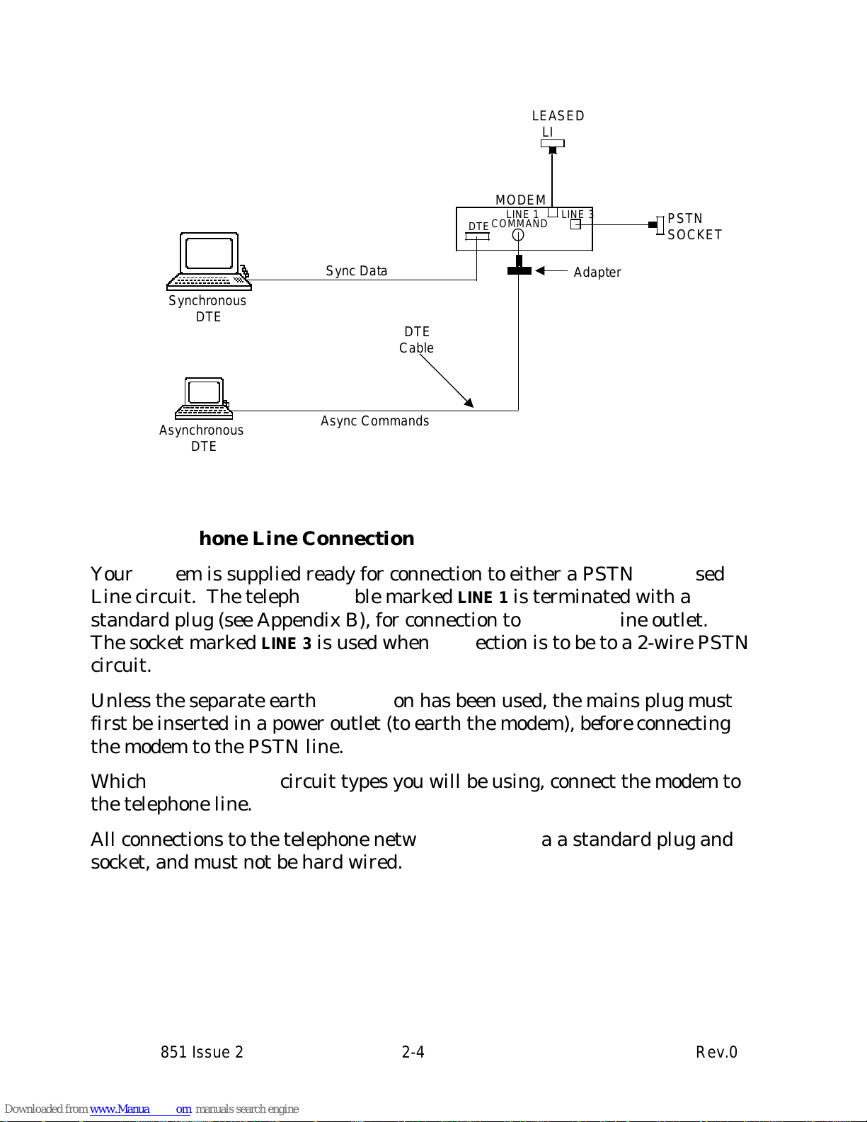
Figure 2-1 Standalone Modem Connections
aaaaaaaaaaaaaaa
a
a
aaaaaaaaaaaaa
a
a
a
aaaaaaaaaaaaa
a
a
a
aaaaaaaaaaaaa
a
a
a
aaaaaaaaaaaaa
a
a
a
aaaaaaaaaaaaa
a
a
Synchronous
DTE
aaaaa
a
aaa
a
a
aaa
a
a
aaa
a
DTE
aaaaaaaaaaaaa
a
aaaaaaaaaaa
a
a
aaaaaaaaaaa
a
COMMAND
aaaaaaa
a
aaaaa
a
a
aaaaa
a
LINE 3
aaaaaaaaaaa
a
aaaaaaaaa
a
a
aaaaaaaaa
a
a
aaaaaaaaa
a
a
aaaaaaaaa
a
a
aaaaaaaaa
a
aaaaaaaaa
PSTN
SOCKET
aaaaaaaaaaa
a
a
aaaaaaaaa
a
a
a
aaaaaaaaa
a
a
MODEM
aaaaaaaaaaaaa
a
aaaaaaaaaaa
a
a
aaaaaaaaaaa
a
a
aaaaaaaaaaa
a
Sync Data
aaaaaaaaaaaaaaaaa
a
a
aaaaaaaaaaaaaaa
a
a
a
aaaaaaaaaaaaaaa
a
a
a
aaaaaaaaaaaaaaa
a
a
a
aaaaaaaaaaaaaaa
a
a
a
aaaaaaaaaaaaaaa
a
a
a
aaaaaaaaaaaaaaa
a
a
Asynchronous
DTE
aaaaaaaaaaaaaaaaaaaaa
a
a
aaaaaaaaaaaaaaaaaaa
a
a
a
aaaaaaaaaaaaaaaaaaa
a
a
a
aaaaaaaaaaaaaaaaaaa
a
a
Async Commands
aaaaaaa
a
a
aaaaa
a
a
a
aaaaa
a
a
a
aaaaa
a
a
a
aaaaa
a
a
a
aaaaa
a
a
DTE
Cable
aaaaaaaaaaa
a
aaaaaaaaa
a
a
aaaaaaaaa
a
Adapter
aaaaaaa
a
aaaaa
a
a
aaaaa
a
LINE 1
aaaaaaaaaaa
a
aaaaaaaaa
a
a
aaaaaaaaa
a
a
aaaaaaaaa
a
a
aaaaaaaaa
a
a
aaaaaaaaa
a
a
aaaaaaaaa
a
LEASED
LINE
2.3.4 Telephone Line Connection
Your modem is supplied ready for connection to either a PSTN or Leased
Line circuit. The telephone cable marked
LINE 1 is terminated with a
standard plug (see Appendix B), for connection to a Leased Line outlet.
The socket marked
LINE 3 is used when connection is to be to a 2-wire PSTN
circuit.
Unless the separate earth connection has been used, the mains plug must
first be inserted in a power outlet (to earth the modem), before connecting
the modem to the PSTN line.
Whichever of the two circuit types you will be using, connect the modem to
the telephone line.
All connections to the telephone network must be via a standard plug and
socket, and must not be hard wired.
X450-310851 Issue 2 2-4 Rev.0
Page 25

2.4 Installing the Rackmount Modem
The modem should only be used in a rack system for which it has been
designed and approved. Full installation details are given in the manual
for the rack system.
2.4.1 Power Supply Connection
The rackmount modem draws its power from the rack power supply. There
is no power switch on the modem.
2.4.2 DTE Port Connection
The connections for the modem's DTE port are via the 96-way connectors
between the modem circuit board and the rack system. Connections to the
DTE are made from the back of the rack. See Appendix B.
2.4.3 Command Port Connection
The connections for the modem's command port are via the 96-way
connectors between the modem circuit board and the rack system. See
Appendix B.
The format and speed for the command port is fixed at 7 data bits, even
parity, 1200 bps.
2.4.4 Telephone Line Connection
The modem's connections for the telephone line are via the 96-way
connectors between the modem circuit board and the rack system.
Connections to the telephone line are made from the back of the rack. See
the rack system manual for details.
X450-310851 Issue 2 2-5 Rev.0
Page 26

2.5 Confidence Check
When the modem installation is complete, a brief confidence check may be
carried out to check that the modem is functioning.
2.5.1 Standalone Modem
1. Ensure that the modem power switch is off.
2. Check that all the front panel buttons are out.
3. Push in and hold in the
DATA button.
4. Switch on the modem power switch (while holding in the
DATA button).
5. Keep the
DATA button held in for 3 seconds then release it. The modem
is now in its factory default condition. It will send a RESTART message to
the command terminal.
6. Press in the
TEST button and then the AL button. The modem will
perform an analogue loop test and the
RUN LED will begin to flash.
7. Check the
DSR LED. It should stay off permanently. If it flashes on, an
error has been detected. In this case recheck the installation: if no
mistakes are found refer to your supplier.
8. Press the
AL and TEST buttons to release them.
2.5.2 Rackmount Modem
1. Fit the modem in the card guides of the rack, but not pushed fully home.
2. Check that all the front panel buttons are out.
3. Push in and hold in the
DA button.
4. Push the modem firmly into the rack (while holding in the
DA button).
5. Keep the
DA button held in for 3 seconds then release it. The modem is
now in its factory default condition. It will send a RESTART message to
the command terminal.
6. Press in the
TE button and then the AL button. The modem will perform
an analogue loop test and the
RUN LED will begin to flash.
7. Check the
DSR LED. It should stay off permanently. If it flashes on, an
error has been detected. In this case recheck the installation: if no
mistakes are found refer to your supplier.
X450-310851 Issue 2 2-6 Rev.0
Page 27

8. Press the AL and TE buttons to release them.
9. Secure the modem in the rack.
X450-310851 Issue 2 2-7 Rev.0
Page 28

X450-310851 Issue 2 2-8 Rev.0
Page 29

3 Getting Started
This chapter covers basic details of how to set up your modem in a straightforward environment: how to control the modem from your DTE, and how
to use the AT command language to make a call whilst the modem is in its
default condition.
3.1 Starting Up
Before using the modem, ensure that it has been installed correctly as
described in Chapter 2.
The factory default is configuration 0 (described in Section 4.1). As this is
suitable for many uses on leased lines, you may not need to reconfigure the
modem. If this is so, follow the procedure below, checking that the modem
and command terminal (which may be the data DTE) respond as indicated.
1. Switch on the DTE and the command terminal.
2. Switch on the modem. The LED indicators on the front panel will reflect
the status of the DTE interface.
TXD, RXD and OH should be off.
3. Load the default factory configuration 0, as follows. Make sure all the
buttons on the modem's front panel are OUT. Press the
LOAD (L) button,
press and release the
ENTER (
|
) button, then release the LOAD (L) button.
4. Type the command AT on the command terminal keyboard and press
RETURN. The message OK should be displayed on the screen.
If factory configuration 0 is not suitable for your operation, go to Chapter 4
to choose a more suitable configuration, and repeat the procedure above,
using the buttons shown in Table 4-1 during step 3.
For example, to load configuration 10, ensure that buttons
2 and DIAL (D)
are in, and that all other buttons are out, before pressing
LOAD (L). After
pressing
ENTER (
|
), release LOAD (L), 2 and DIAL (D).
X450-310851 Issue 2 3-1 Rev.0
Page 30

3.2 Commanding the Modem
3.2.1 The AT Command Set
Your modem uses the 'AT' command set. These commands are used to
exercise the powerful features of your modem, such as:
• Making user configurations.
• Saving telephone numbers in the modem's directory.
• Auto-dialling telephone numbers.
• Performing modem tests.
Section 3.3 provides an explanation of the AT command language with
simple working examples. We recommend you to read this even if you have
used AT commands before.
The AT commands are listed alphabetically in Chapter 8.
3.2.2 The V.25bis Command Set
ITU-T has defined the V.25bis Recommendation for commands. However,
it is much more limited than the AT command set, as it only covers dialling
a telephone number. Your modem has been equipped with a V.25bis
command set to make it compatible with hosts using software based on this
language. Details are in Chapter 10.
X450-310851 Issue 2 3-2 Rev.1
Page 31

3.3 The AT Command Format
3.3.1 Basic Format
AT (attention) is the prefix to commands to the modem. It must be typed:
AT or at
in all upper or all lower case (not mixed cases).
Carriage return (<CR>) is the terminator to commands, causing the
modem to action them. It is produced by the
RETURN, ENTER or
|
key on your
DTE.
For example, if from your keyboard you type:
AT<CR>
the modem will respond with:
OK
AT by itself (followed by <CR>) is a command without any required
action. Your modem responding with OK indicates that it has recognised
the AT. This sequence is useful for checking that the modem is responding
correctly.
3.3.2 Example Commands
A useful command is *C, which will display a summary of your modem's
configuration. To execute this command, type:
AT*C<CR>
Another useful command is *S, which will display a summary of your
modem's S-register settings (S-registers are discussed in Chapter 9). To
execute this command, type:
AT*S<CR>
3.3.3 Combining Commands
If you wish to enter two or more commands, they can be combined on a
single command line up to a maximum of 80 characters, for example:
AT*C*S<CR>
will display your modem's configuration and then the S-register summary.
X450-310851 Issue 2 3-3 Rev.0
Page 32

You can use space characters between commands to increase their
legibility, for instance:
AT
*C *S<CR>
will give an identical response to the previous sequence.
The only commands that cannot form part of a command string are %D, &F,
&L, %W, %X, Z, &Z and %Z.
3.3.4 Repeating Commands
You can cause the modem to repeat the last command sequence entered. If
you now type:
A/
this will cause the previous AT *C *S sequence to be repeated. Note that
this is an exception to the rule: it requires neither the AT prefix nor the
<CR> terminator.
3.3.5 Editing a Command Line
If you make a mistake when entering a command line, you can use the
backspace key to reposition the cursor and you can then correct the
mistake by overtyping.
3.3.6 Command Option Numbers
Some commands require you to enter a number (often referred to as n) to
specify one of a list of options (e.g. ATF4). If you omit the number, 0 is
assumed (for example ATE is the same as ATE0).
3.3.7 The OK Response
When a ''configuration'' command is successfully executed, the message OK
is returned by the modem. No messages are generated with ''dialling''
commands.
3.3.8 Response Codes
The result of entering commands can be sent to the terminal in various
forms, as selected by certain commands (X and /S).
X450-310851 Issue 2 3-4 Rev.0
Page 33

3.4 Making a Call
When you have successfully followed the start-up procedure in Section 3.1,
the modem should be ready for operation. If you are using the PSTN, you
will need to make a call.
3.4.1 Dialling
To dial a number from your command terminal, type ATD followed directly
by the number you want to dial, then press
RETURN. For example, to dial
0123 456789 type ATD0123456789 <CR>.
If you are connected to a PBX line, the number for an outside line (for
example 9), must be inserted immediately before the number you want to
dial. On some older PBXs you may need to insert a comma after the
number for an outside line, to cause a delay before the modem continues
dialling, for example ATD9,0123456789 <CR>.
3.4.2 Call Progress
During the progress of the connection, various messages may appear on the
screen:
RINGING while the ringing tone can be detected from the remote
end.
CONNECT after successful connection to the number you are
calling.
If there are problems, the following messages may appear:
DIALTONE if the modem detects dial tone when it is not expected.
The modem then disconnects the call.
NO DIALTONE if dial tone is not detected when the modem goes on
line.
NO ANSWER if the number you are calling does not answer. The
modem disconnects automatically.
VOICE if the call is answered but answer tone is not detected.
This usually means that the call has been answered by
a person rather than a modem.
NO CARRIER if the modem you are calling 'answers' but cannot
communicate with your modem.
X450-310851 Issue 2 3-5 Rev.0
Page 34

ABORTED indicates that the DTR signal is not present on the DTE
interface, i.e. your DTE is not ready.
3.4.3 Connection
A successful connection allows your DTE to transfer data to and from the
remote DTE.
If the call has connected you to a data service, a sign-on message should
appear on the screen. For advice on what to do next, consult the
documentation for the service accessed. Alternatively, disconnect the call
as described below.
3.4.4 Disconnection
To disconnect the call, type:
ATH
and press
RETURN. This produces the message:
OK
Note that a call can only be disconnected after it has been fully connected.
After receiving OK to ATH, you can dial further numbers or activate any of
the modem's other facilities.
X450-310851 Issue 2 3-6 Rev.0
Page 35

3.5 Receiving Calls
The modem is configured so that it will automatically answer an incoming
call after three rings, and connect to the data DTE. When the call is
completed, the modem will be ready to receive further calls, or for you to
make outgoing calls.
X450-310851 Issue 2 3-7 Rev.0
Page 36

X450-310851 Issue 2 3-8 Rev.0
Page 37

PART 2
ADVANCED OPERATION
Chapter 4 Modem Configurations
Chapter 5 Advanced Configuration
Chapter 6 Operational Facilities
Chapter 7 Diagnostic Facilities
Chapter 8 The AT Commands
Chapter 9 The S-Registers
Chapter 10 V.25bis Commands
X450-310851 Issue 2 4-1 Rev.0
Page 38

X450-310851 Issue 2 4-2 Rev.0
Page 39

4 Modem Configurations
4.1 Factory Configurations
4.1.1 Introduction
In order to be able to match a wide variety of situations, your modem
incorporates very versatile communications capabilities, user features, and
automatic facilities. These include, for example:
– data transmission speeds,
– data transmission protocols,
– operational facilities (e.g. automatic dialling).
To simplify the task of configuring your modem, you can choose one of the
twelve pre-configured ''factory configurations'' that cover standard
applications. They are described in this section. Four more standard
applications are stored in the ''user configuration'' locations, described in
Section 4.2.
Should the standard configurations not be exactly what you need, you can
choose the one nearest to your requirements, modify it as necessary, and
store it as a ''user configuration'' in non-volatile memory, as described in
Section 4.2.
Then, to configure your modem, you only need to load the appropriate
configuration, either from the front panel as described in Section 4.3, or by
command (&F) as described in Section 4.4.
X450-310851 Issue 2 4-3 Rev.0
Page 40

4.1.2 Factory Configuration List
The following standard factory configurations are provided:
Configuration Description
0 V.32bis, 14400 bps, 2-wire leased line in answer mode,
security control.
1 V.32bis, 14400 bps, 2-wire leased line in originate mode,
security control.
2 V.32bis, 14400 bps, 2-wire leased line, originate mode
with autodial backup and security, no autorestoral.
3 V.32bis, 14400 bps, 2-wire leased line, originate mode
with autodial backup, security and autorestoral.
4 V.32bis, 14400 bps, PSTN, V.25bis Byte sync dialup,
security.
5 V.32bis, 14400 bps, PSTN, V.25bis HDLC sync dialup,
security.
6 V.32bis, 14400 bps, 4-wire leased line, answer mode.
7 V.32bis, 14400 bps, 4-wire leased line, originate mode.
8 V.33, 14400 bps, 4-wire leased line operation.
9 V.32bis, 14400 bps, PSTN, manual dial.
10 V.32bis, 14400 bps, PSTN, dial on DTR, security control.
11 V.33, 14400 bps, 4-wire leased line, originate mode with
autodial backup, security and autorestoral.
For convenience, the additional standard configurations stored in the user
configuration locations are also listed here:
0 V.32bis, 12000 bps, PSTN, for dial backup with manual
restoral to the leased line.
1 V.32bis, 14400 bps, PSTN, for dial backup with
autorestoral to the leased line.
2 V.32bis, 14400 bps, PSTN, for dial backup with manual
restoral to the leased line.
3 V.29, 9600 bps, 4-wire leased line with 4800 bps fallback.
X450-310851 Issue 2 4-4 Rev.0
Page 41

These may be user-modified, but can be recalled to the default
configurations by resetting the modem.
Factory configurations 4, 5, 9 and 10 are suitable for PSTN operation. The
remainder are suitable for leased line (private wire) operation.
Configurations 4 and 5 are suitable for DTEs which issue V.25bis dialling
commands.
The default user configurations are suitable for dial backup operation.
In the following explanations, the full specification of each configuration is
shown as it would be presented on the DTE screen by use of the *C
command (see Chapter 8). For each parameter it shows the AT command
code, the command name, and the selected option.
Control Signals
The connection between the modem and the DTE includes a number of
control signals, which are monitored by the front panel indicators (see
Section 1.2.1).
The way these signals are used is controlled by the configuration in use. In
the following descriptions of the configurations, each control signal is
described as being in one of three modes. These are:
Normal The signal is sent in the normal manner. In this mode,
DTE signals must be controlled properly by the
originating DTE.
Forced On This can apply to control signals originated by the
modem. The modem sets the signal to the ON state at
all times. It therefore has no meaning as a control
signal, but is used to make the DTE function correctly.
Ignored This can apply to control signals originated by the
DTE. The modem ignores any changes in the signal
state and behaves as if the signal were permanently
ON. It is not necessary to have a connection to the
signal's pin on the DTE port connector.
Note that these modes can be changed by AT commands (described in
subsequent chapters).
For details of the significance of the control signals, refer to ITU-T
Recommendation V.24.
X450-310851 Issue 2 4-5 Rev.1
Page 42

4.1.3 Factory Configuration Specifications
Factory Configuration 0
Operation : Leased line, V.32bis, answer mode.
Rates : Primary 14400, fallback 12000.
V.24 : Normal.
Commands : AT via the command port.
Typical Use : The modem is set to answer mode and must always be
used with an originate modem (e.g. factory configuration
1) at the remote end of the link.
Configuration Screen F0
F36 Communication Format 14400 V32bis *V0 Command Mode AT
X6 Result Codes ALL *W0 DSR Control NORMAL
&B0 Busy Out Control DISABLED ”A1 Leased Line Mode ANSWER
&G0 Guard tone OFF ”D0 Restore on DTR DISABLED
&L1 Line Mode 2W LEASE LINE ”E1 Security Control ENABLED
&Q1 Operation Mode SYNC ASYNC DIAL ”N3 Remote Logon ORIG & ANS
&R0 RTS/CTS Delay 0mS ”Q0 Quality Mon LL DISABLED
&S1 Switches ENABLED /B1 Carrier CONSTANT
&X0 Timing Source INTERNAL /C1 Cable Equaliser ENABLED
%B0 Pin 23 Fallback DISABLED /D1 DCD Threshold –33dB
%E7 Remote Control USER & LINE /F35 Fallback Format 12000 V32bis
%F0 Fallback DISABLED /G1 T/2 Equaliser ENABLED
%Q0 Interface Control DISABLED /Q0 Quality Mon PSTN DISABLED
*B1 S10 DCD Timeout 40 Secs /R1 S26 Base RTS/CTS X 1mS
*M0 Data Monitor OFF /S1 Response EXTENDED
*R0 RTS Clamp OFF /T4 Test Pattern MARKS/ERR INJ
*T1 DCD Timeout LOSS /W1 S37 Mon. Timeout 0 Mins
*L5 Dial backup 2-WIRE ON /Y2 Re-Training AUTO RETRAIN
TIMEOUT
X450-310851 Issue 2 4-6 Rev.0
Page 43

Factory Configuration 1
Operation : Leased line, V.32bis, originate mode.
Rates : Primary 14400, fallback 12000.
V.24 : Normal.
Commands : AT via the command port.
Typical Use : In this mode the modem operates purely as a 2-wire leased
line modem, synchronously at 14400 bps. The modem is
set to originate mode. This configuration may be used in
conjunction with factory configuration 0 at the remote
end.
Configuration Screen F1
F36 Communication Format 14400 V32bis *V0 Command Mode AT
X6 Result Codes ALL *W0 DSR Control NORMAL
&B0 Busy Out Control DISABLED ”A0 Leased Line Mode ORIGINATE
&G0 Guard tone OFF ”D1 Restore on DTR ENABLED
&L1 Line Mode 2W LEASE LINE ”E1 Security Control ENABLED
&Q1 Operation Mode SYNC ASYNC DIAL ”N3 Remote Logon ORIG & ANS
&R0 RTS/CTS Delay 0mS ”Q0 Quality Mon LL DISABLED
&S1 Switches ENABLED /B1 Carrier CONSTANT
&X0 Timing Source INTERNAL /C1 Cable Equaliser ENABLED
%B0 Pin 23 Fallback DISABLED /D1 DCD Threshold –33dB
%E7 Remote Control USER & LINE /F35 Fallback Format 12000 V32bis
%F0 Fallback DISABLED /G1 T/2 Equaliser ENABLED
%Q0 Interface Control DISABLED /Q0 Quality Mon PSTN DISABLED
*B1 S10 DCD Timeout 45 Secs /R1 S26 Base RTS/CTS X 1mS
*M0 Data Monitor OFF /S1 Response EXTENDED
*R0 RTS Clamp OFF /T4 Test Pattern MARKS/ERR INJ
*T1 DCD Timeout LOSS /W1 S37 Mon. Timeout 0 Mins
*L0 Dial backup DISABLED /Y2 Re-Training AUTO RETRAIN
X450-310851 Issue 2 4-7 Rev.0
Page 44

Factory Configuration 2
Operation : Leased line, V.32bis, automatic dial backup
Rates : Primary 14400, fallback 12000.
V.24 : Normal.
Commands : AT via the command port.
Typical Use : The modem operates in originate mode. Automatic dial
backup is enabled and on originating a dial backup
connection, the modem will perform a password check on
the answering modem. Once verified, transmission is
switched to the dial line. Disconnection and return to
leased line operation is by AT command, at either end of
the link.
A default password has been stored in the modem. If this
is deleted, the modem will omit the password check and
merely verify the state of the PSTN line before switching
to dial backup.
The configuration for dial backup may be stored in a user
configuration location and associated with the
appropriate telephone number.
The telephone number for automatic dial backup must be
stored in the modem in location N8 of the dialling-end
modem, which is then the master modem for dial backup
operation.
X450-310851 Issue 2 4-8 Rev.0
Page 45

Configuration Screen F2
F36 Communication Format 14400 V32bis *V0 Command Mode AT
X6 Result Codes ALL *W0 DSR Control NORMAL
&B0 Busy Out Control DISABLED ”A0 Leased Line Mode ORIGINATE
&G0 Guard tone OFF ”D0 Restore on DTR DISABLED
&L1 Line Mode 2W LEASE LINE ”E1 Security Control ENABLED
&Q1 Operation Mode SYNC ASYNC DIAL ”N3 Remote Logon ORIG & ANS
&R0 RTS/CTS Delay 0mS ”Q0 Quality Mon LL DISABLED
&S1 Switches ENABLED /B1 Carrier CONSTANT
&X0 Timing Source INTERNAL /C1 Cable Equaliser ENABLED
%B0 Pin 23 Fallback DISABLED /D1 DCD Threshold –33dB
%E7 Remote Control USER & LINE /F35 Fallback Format 12000 V32bis
%F0 Fallback DISABLED /G1 T/2 Equaliser ENABLED
%Q0 Interface Control DISABLED /Q0 Quality Mon PSTN DISABLED
*B1 S10 DCD Timeout 40 Secs /R1 S26 Base RTS/CTS X 1mS
*M0 Data Monitor OFF /S1 Response EXTENDED
*R0 RTS Clamp OFF /T4 Test Pattern MARKS/ERR INJ
*T1 DCD Timeout LOSS /W1 S37 Mon. Timeout 0 Mins
*L5 Dial backup 2-WIRE ON /Y2 Re-Training AUTO RETRAIN
TIMEOUT
X450-310851 Issue 2 4-9 Rev.0
Page 46

Factory Configuration 3
Operation : Leased line, V.32bis, automatic dial backup and restoral.
Rates : Primary 14400, fallback 12000.
V.24 : Normal.
Commands : AT via the command port.
Typical Use : The modem operates with automatic dial backup and
restoral to leased line. Dial backup is automatically
initiated if the leased line connection is lost.
If the modem subsequently detects that the leased line has
recovered, the dial backup connection is automatically
broken and transmission is restored to the leased line.
The telephone number for automatic dial backup must be
stored in the modem in N8 of the dialling-end modem.
A default password has been stored in the modem. If this
is deleted, the modem will omit the password check and
merely verify the state of the PSTN line before switching
to dial backup. The configuration for dial backup may be
stored in a user configuration location. For further
information on dial backup see Section 6.4.
X450-310851 Issue 2 4-10 Rev.0
Page 47

Configuration Screen F3
F36 Communication Format 14400 V32bis *V0 Command Mode AT
X6 Result Codes ALL *W0 DSR Control NORMAL
&B0 Busy Out Control DISABLED ”A0 Leased Line Mode ORIGINATE
&G0 Guard tone OFF ”D0 Restore on DTR DISABLED
&L1 Line Mode 2W LEASE LINE ”E1 Security Control ENABLED
&Q1 Operation Mode SYNC ASYNC DIAL ”N3 Remote Logon ORIG & ANS
&R0 RTS/CTS Delay 0mS ”Q0 Quality Mon LL DISABLED
&S1 Switches ENABLED /B1 Carrier CONSTANT
&X0 Timing Source INTERNAL /C1 Cable Equaliser ENABLED
%B0 Pin 23 Fallback DISABLED /D1 DCD Threshold –33dB
%E7 Remote Control USER & LINE /F35 Fallback Format 12000 V32bis
%F0 Fallback DISABLED /G1 T/2 Equaliser ENABLED
%Q0 Interface Control DISABLED /Q0 Quality Mon PSTN DISABLED
*B1 S10 DCD Timeout 40 Secs /R1 S26 Base RTS/CTS X 1mS
*M0 Data Monitor OFF /S1 Response EXTENDED
*R0 RTS Clamp OFF /T4 Test Pattern MARKS/ERR INJ
*T1 DCD Timeout LOSS /W1 S37 Mon. Timeout 0 Mins
*L13 Dial backup 2-WIRE & /Y2 Re-Training AUTO RETRAIN
AUTO-RES
X450-310851 Issue 2 4-11 Rev.0
Page 48

Factory Configuration 4
Operation : PSTN, V.32bis.
Rates : Primary 14400, fallback 12000.
V.24 : DTR conforms to ITU-T 108/2 (call disconnected on loss of
DTR).
Commands : AT via the command port. V.25bis Byte via DTE port.
Typical Use : The modem operates as a 2-wire, full duplex 14400 bps
dialup modem. Calls are initiated in V.25bis Byte
synchronous format via the main data channel, and the
command port is active for AT commands
.
Configuration Screen F4
F36 Communication Format 14400 V32bis *V2 Command Mode V25 BYTE
X6 Result Codes ALL *W0 DSR Control NORMAL
&B0 Busy Out Control DISABLED ”A0 Leased Line Mode ORIGINATE
&G0 Guard tone OFF ”D0 Restore on DTR DISABLED
&L0 Line Mode 2W PSTN ”E1 Security Control ENABLED
&Q3 Operation Mode SYNC MANUAL DIAL ”N3 Remote Logon ORIG & ANS
&R0 RTS/CTS Delay 0mS ”Q0 Quality Mon LL DISABLED
&S1 Switches ENABLED /B1 Carrier CONSTANT
&X0 Timing Source INTERNAL /C1 Cable Equaliser ENABLED
%B0 Pin 23 Fallback DISABLED /D0 DCD Threshold –43dB
%E7 Remote Control USER & LINE /F35 Fallback Format 12000 V32bis
%F0 Fallback DISABLED /G1 T/2 Equaliser ENABLED
%Q1 Interface Control ENABLED /Q0 Quality Mon PSTN DISABLED
*B1 S10 DCD Timeout 40 Secs /R1 S26 Base RTS/CTS X 1mS
*M0 Data Monitor OFF /S1 Response EXTENDED
*R0 RTS Clamp OFF /T4 Test Pattern MARKS/ERR INJ
*T1 DCD Timeout LOSS /W1 S37 Mon. Timeout 0 Mins
*L0 Dial backup DISABLED /Y2 Re-Training AUTO RETRAIN
X450-310851 Issue 2 4-12 Rev.1
Page 49

Factory Configuration 5
Operation : PSTN, V.32bis.
Rates : Primary 14400, fallback 12000.
V.24 : DTR conforms to ITU-T 108/2 (call disconnected on loss of
DTR).
Commands : AT via the command port, V.25bis HDLC via the DTE
port.
Typical Use : The modem operates as a 2-wire, full duplex 14400 bps
dialup modem. Calls are initiated in V.25bis HDLC
synchronous format via the main data channel, and the
command port is active for AT commands.
Configuration Screen F5
F36 Communication Format 14400 V32bis *V3 Command Mode V25 HDLC
X6 Result Codes ALL *W0 DSR Control NORMAL
&B0 Busy Out Control DISABLED ”A0 Leased Line Mode ORIGINATE
&G0 Guard tone OFF ”D0 Restore on DTR DISABLED
&L0 Line Mode 2W PSTN ”E1 Security Control ENABLED
&Q3 Operation Mode SYNC MANUAL DIAL ”N3 Remote Logon ORIG & ANS
&R0 RTS/CTS Delay 0mS ”Q0 Quality Mon LL DISABLED
&S1 Switches ENABLED /B1 Carrier CONSTANT
&X0 Timing Source INTERNAL /C1 Cable Equaliser ENABLED
%B0 Pin 23 Fallback DISABLED /D0 DCD Threshold –43dB
%E7 Remote Control USER & LINE /F35 Fallback Format 12000 V32bis
%F0 Fallback DISABLED /G1 T/2 Equaliser ENABLED
%Q1 Interface Control ENABLED /Q0 Quality Mon PSTN DISABLED
*B1 S10 DCD Timeout 40 Secs /R1 S26 Base RTS/CTS X 1mS
*M0 Data Monitor OFF /S1 Response EXTENDED
*R0 RTS Clamp OFF /T4 Test Pattern MARKS/ERR INJ
*T1 DCD Timeout LOSS /W1 S37 Mon. Timeout 0 Mins
*L0 Dial backup DISABLED /Y2 Re-Training AUTO RETRAIN
X450-310851 Issue 2 4-13 Rev.1
Page 50

Factory Configuration 6
Operation : 4-wire leased line, V.32bis, answer mode.
Rates : Primary 14400, fallback 12000.
V.24 : Normal.
Commands : AT via the command port.
Typical Use : The modem is set to answer mode. Although set to 4-wire
operation it is necessary in V.32bis mode to set an
originate configuration at the other end of the link.
Factory configuration 7 is provided for this purpose.
Configuration Screen F6
F36 Communication Format 14400 V32bis *V0 Command Mode AT
X6 Result Codes ALL *W0 DSR Control NORMAL
&B0 Busy Out Control DISABLED ”A1 Leased Line Mode ANSWER
&G0 Guard tone OFF ”D0 Restore on DTR DISABLED
&L3 Line Mode 4W PRIVATE LINE ”E1 Security Control ENABLED
&Q1 Operation Mode SYNC ASYNC DIAL ”N3 Remote Logon ORIG & ANS
&R0 RTS/CTS Delay 0mS ”Q0 Quality Mon LL DISABLED
&S1 Switches ENABLED /B1 Carrier CONSTANT
&X0 Timing Source INTERNAL /C1 Cable Equaliser ENABLED
%B0 Pin 23 Fallback DISABLED /D1 DCD Threshold –33dB
%E7 Remote Control USER & LINE /F35 Fallback Format 12000 V32bis
%F0 Fallback DISABLED /G1 T/2 Equaliser ENABLED
%Q0 Interface Control DISABLED /Q0 Quality Mon PSTN DISABLED
*B1 S10 DCD Timeout 40 Secs /R1 S26 Base RTS/CTS X 1mS
*M0 Data Monitor OFF /S1 Response EXTENDED
*R0 RTS Clamp OFF /T4 Test Pattern MARKS/ERR INJ
*T1 DCD Timeout LOSS /W1 S37 Mon. Timeout 0 Mins
*L0 Dial backup DISABLED /Y2 Re-Training AUTO RETRAIN
X450-310851 Issue 2 4-14 Rev.0
Page 51

Factory Configuration 7
Operation : 4-wire leased line, V.32bis, originate mode.
Rates : Primary 14400, fallback 12000.
V.24 : Normal.
Commands : AT via the command port.
Typical Use : The modem is set to originate mode. Although set to 4-
wire operation it is necessary in V.32bis mode to set an
answer configuration at the other end of the link. Factory
configuration 6 is provided for this purpose.
Configuration Screen F7
F36 Communication Format 14400 V32bis *V0 Command Mode AT
X6 Result Codes ALL *W0 DSR Control NORMAL
&B0 Busy Out Control DISABLED ”A0 Leased Line Mode ORIGINATE
&G0 Guard tone OFF ”D0 Restore on DTR DISABLED
&L3 Line Mode 4W PRIVATE LINE ”E1 Security Control ENABLED
&Q1 Operation Mode SYNC ASYNC DIAL ”N3 Remote Logon ORIG & ANS
&R0 RTS/CTS Delay 0mS ”Q0 Quality Mon LL DISABLED
&S1 Switches ENABLED /B1 Carrier CONSTANT
&X0 Timing Source INTERNAL /C1 Cable Equaliser ENABLED
%B0 Pin 23 Fallback DISABLED /D1 DCD Threshold –33dB
%E7 Remote Control USER & LINE /F35 Fallback Format 12000 V32bis
%F0 Fallback DISABLED /G1 T/2 Equaliser ENABLED
%Q0 Interface Control DISABLED /Q0 Quality Mon PSTN DISABLED
*B1 S10 DCD Timeout 40 Secs /R1 S26 Base RTS/CTS X 1mS
*M0 Data Monitor OFF /S1 Response EXTENDED
*R0 RTS Clamp OFF /T4 Test Pattern MARKS/ERR INJ
*T1 DCD Timeout LOSS /W1 S37 Mon. Timeout 0 Mins
*L0 Dial backup DISABLED /Y2 Re-Training AUTO RETRAIN
X450-310851 Issue 2 4-15 Rev.0
Page 52

Factory Configuration 8
Operation : 4-wire leased line, V.33.
Rates : Primary 14400, fallback 12000.
V.24 : Normal.
Commands : AT via the command port.
Typical Use : The modem operates as a 4-wire leased line modem,
synchronously at 14400 bps. The remote modem should
also use Factory Configuration 8. The Leased Line Mode,
''A, is ignored by this modulation scheme.
Configuration Screen F8
F28 Communication Format 14400 TCM V33 *V0 Command Mode AT
X6 Result Codes ALL *W0 DSR Control NORMAL
&B0 Busy Out Control DISABLED ”A0 Leased Line Mode ORIGINATE
&G0 Guard tone OFF ”D0 Restore on DTR DISABLED
&L3 Line Mode 4W PRIVATE LINE ”E1 Security Control ENABLED
&Q1 Operation Mode SYNC ASYNC DIAL ”N3 Remote Logon ORIG & ANS
&R0 RTS/CTS Delay 0mS ”Q0 Quality Mon LL DISABLED
&S1 Switches ENABLED /B1 Carrier CONSTANT
&X0 Timing Source INTERNAL /C1 Cable Equaliser ENABLED
%B0 Pin 23 Fallback DISABLED /D1 DCD Threshold –33dB
%E7 Remote Control USER & LINE /F27 Fallback Format 12000 TCM V33
%F0 Fallback DISABLED /G1 T/2 Equaliser ENABLED
%Q0 Interface Control DISABLED /Q0 Quality Mon PSTN DISABLED
*B1 S10 DCD Timeout 40 Secs /R1 S26 Base RTS/CTS X 1mS
*M0 Data Monitor OFF /S1 Response EXTENDED
*R0 RTS Clamp OFF /T4 Test Pattern MARKS/ERR INJ
*T1 DCD Timeout LOSS /W1 S37 Mon. Timeout 0 Mins
*L0 Dial backup DISABLED /Y2 Re-Training AUTO RETRAIN
X450-310851 Issue 2 4-16 Rev.0
Page 53

Factory Configuration 9
Operation : PSTN, V.32bis.
Rates : Primary 14400, fallback 12000.
V.24 : DTR conforms to ITU-T 108/2 (call disconnected on loss of
DTR)
Commands : AT via the command port.
Typical Use : This is a dial-up 14400 bps manual dial configuration.
Dialling can be either via the command port or the front
panel (see Chapter 8 for further information).
Security is enabled so the remote modem must also
support this facility and have the password and key set
correctly (see Section 5.6 for further information).
Configuration Screen F9
F36 Communication Format 14400 V32bis *V0 Command Mode AT
X6 Result Codes ALL *W0 DSR Control NORMAL
&B0 Busy Out Control DISABLED ”A0 Leased Line Mode ORIGINATE
&G0 Guard tone OFF ”D0 Restore on DTR DISABLED
&L0 Line Mode 2W PSTN ”E1 Security Control ENABLED
&Q3 Operation Mode SYNC MANUAL DIAL ”N3 Remote Logon ORIG & ANS
&R0 RTS/CTS Delay 0mS ”Q0 Quality Mon LL DISABLED
&S1 Switches ENABLED /B1 Carrier CONSTANT
&X0 Timing Source INTERNAL /C1 Cable Equaliser ENABLED
%B0 Pin 23 Fallback DISABLED /D1 DCD Threshold –43dB
%E7 Remote Control USER & LINE /F35 Fallback Format 12000 V32bis
%F0 Fallback DISABLED /G1 T/2 Equaliser ENABLED
%Q0 Interface Control DISABLED /Q0 Quality Mon PSTN DISABLED
*B1 S10 DCD Timeout 40 Secs /R1 S26 Base RTS/CTS X 1mS
*M0 Data Monitor OFF /S1 Response EXTENDED
*R0 RTS Clamp OFF /T4 Test Pattern MARKS/ERR INJ
*T1 DCD Timeout LOSS /W1 S37 Mon. Timeout 0 Mins
*L0 Dial backup DISABLED /Y2 Re-Training AUTO RETRAIN
X450-310851 Issue 2 4-17 Rev.1
Page 54

Factory Configuration 10
Operation : PSTN, V.32bis.
Rates : Primary 14400, fallback 12000.
V.24 : DTR Dialling.
Commands : AT via the command port.
Typical Use : The modem operates as an autodial and autoanswer
modem. Dialling is initiated when the terminal raises
DTR. The telephone number to be used must be stored in
location N0. S-register S25 must be set to 0.
Configuration Screen F10
F36 Communication Format 14400 V32bis *V0 Command Mode AT
X6 Result Codes ALL *W0 DSR Control NORMAL
&B0 Busy Out Control DISABLED ”A0 Leased Line Mode ORIGINATE
&G0 Guard tone OFF ”D0 Restore on DTR DISABLED
&L0 Line Mode 2W PSTN ”E1 Security Control ENABLED
&Q2 Operation Mode SYNC DTR DIAL ”N3 Remote Logon ORIG & ANS
&R0 RTS/CTS Delay 0mS ”Q0 Quality Mon LL DISABLED
&S1 Switches ENABLED /B1 Carrier CONSTANT
&X0 Timing Source INTERNAL /C1 Cable Equaliser ENABLED
%B0 Pin 23 Fallback DISABLED /D0 DCD Threshold –43dB
%E7 Remote Control USER & LINE /F35 Fallback Format 12000 V32bis
%F0 Fallback DISABLED /G1 T/2 Equaliser ENABLED
%Q0 Interface Control DISABLED /Q0 Quality Mon PSTN DISABLED
*B1 S10 DCD Timeout 40 Secs /R1 S26 Base RTS/CTS X 1mS
*M0 Data Monitor OFF /S1 Response EXTENDED
*R0 RTS Clamp OFF /T4 Test Pattern MARKS/ERR INJ
*T1 DCD Timeout LOSS /W1 S37 Mon. Timeout 0 Mins
*L0 Dial backup DISABLED /Y2 Re-Training AUTO RETRAIN
X450-310851 Issue 2 4-18 Rev.0
Page 55

Factory Configuration 11
Operation : 4-wire leased line, V.33 TCM, auto dial-backup and
restoral.
Rates : Primary 14400, fallback 12000.
V.24 : Normal.
Commands : AT via the command port.
Typical Use : Initiation of dial backup is automatic on loss of signal.
The telephone number for automatic dial backup must be
stored in the modem in N8 of the dialling-end modem,
along with the required PSTN backup configuration.
The remote modem should also use factory configuration
11. No number is stored in N8, indicating that it is the
answering end of the link. The PSTN backup
configuration should be loaded into directory location
N10.
With user configuration Z1 or Z2 stored alongside the dial
backup number, once connected the user configuration is
loaded, typically V.32bis 14400 bps, and transmission is
switched to the dialup line. When the leased line has been
restored and checked, data automatically reverts to V.33
leased line operation and the dialup line is disconnected.
For full details on dial backup while operating in V.33
mode, see Section 6.4 of this manual.
X450-310851 Issue 2 4-19 Rev.0
Page 56

Configuration Screen F11
F28 Communication Format 14400 TCM V33 *V0 Command Mode AT
X6 Result Codes ALL *W0 DSR Control NORMAL
&B0 Busy Out Control DISABLED ”A0 Leased Line Mode ORIGINATE
&G0 Guard tone OFF ”D0 Restore on DTR DISABLED
&L3 Line Mode 4W PRIVATE LINE ”E1 Security Control ENABLED
&Q1 Operation Mode SYNC ASYNC DIAL ”N3 Remote Logon ORIG & ANS
&R0 RTS/CTS Delay 0mS ”Q0 Quality Mon LL DISABLED
&S1 Switches ENABLED /B1 Carrier CONSTANT
&X0 Timing Source INTERNAL /C1 Cable Equaliser ENABLED
%B0 Pin 23 Fallback DISABLED /D1 DCD Threshold –33dB
%E7 Remote Control USER & LINE /F27 Fallback Format 12000 TCM V33
%F0 Fallback DISABLED /G1 T/2 Equaliser ENABLED
%Q0 Interface Control DISABLED /Q0 Quality Mon PSTN DISABLED
*B1 S10 DCD Timeout 40 Secs /R1 S26 Base RTS/CTS X 1mS
*M0 Data Monitor OFF /S1 Response EXTENDED
*R0 RTS Clamp OFF /T4 Test Pattern MARKS/ERR INJ
*T1 DCD Timeout LOSS /W1 S37 Mon. Timeout 0 Mins
*L13 Dial backup 2-WIRE & /Y2 Re-Training AUTO RETRAIN
AUTO-RES
X450-310851 Issue 2 4-20 Rev.0
Page 57

4.2 User Configurations
Your modem contains four ''user configurations''. Initially, these contain
four default configurations (effectively an extension of the factory
configurations in Section 4.1). Details of these are in Section 4.2.1.
Should none of the factory or default configurations be exactly what you
require, you can use the procedure in Section 4.2.2 to create your own
customised configuration(s).
X450-310851 Issue 2 4-21 Rev.0
Page 58

4.2.1 Default User Configurations
The default configurations are designed mainly for use on dial backup
connections.
User Configuration 0
Operation : PSTN, V.32bis, manual restoral.
Rates : Primary 12000, fallback 7200.
V.24 : Normal.
Commands : AT via the command port
Typical Use : This configuration is suitable for use over low quality
backup circuits, and where it is desirable for the user to
decide when the system should revert to the leased line.
Configuration Screen Z0
F35 Communication Format 12000 V32bis *V0 Command Mode AT
X6 Result Codes ALL *W0 DSR Control NORMAL
&B0 Busy Out Control DISABLED ”A1 Leased Line Mode ANSWER
&G0 Guard tone OFF ”D0 Restore on DTR DISABLED
&L0 Line Mode 2W PSTN ”E1 Security Control ENABLED
&Q1 Operation Mode SYNC ASYNC DIAL ”N3 Remote Logon ORIG & ANS
&R0 RTS/CTS Delay 0mS ”Q0 Quality Mon LL DISABLED
&S1 Switches ENABLED /B1 Carrier CONSTANT
&X0 Timing Source INTERNAL /C1 Cable Equaliser ENABLED
%B0 Pin 23 Fallback DISABLED /D0 DCD Threshold –43dB
%E7 Remote Control USER & LINE /F37 Fallback Format 7200 V32bis
%F0 Fallback DISABLED /G1 T/2 Equaliser ENABLED
%Q0 Interface Control DISABLED /Q0 Quality Mon PSTN DISABLED
*B1 S10 DCD Timeout 40 Secs /R1 S26 Base RTS/CTS X 1mS
*M0 Data Monitor OFF /S1 Response EXTENDED
*R0 RTS Clamp OFF /T4 Test Pattern MARKS/ERR INJ
*T1 DCD Timeout LOSS /W1 S37 Mon. Timeout 0 Mins
*L5 Dial backup 2-WIRE ON /Y2 Re-Training AUTO RETRAIN
TIMEOUT
X450-310851 Issue 2 4-22 Rev.0
Page 59

User Configuration 1
Operation : PSTN, V.32bis, autorestoral.
Rates : Primary 14400, fallback 12000.
V.24 : Normal.
Commands : AT via the command port.
Typical Use : This configuration can be used in systems where non-stop
operation is desirable. Data transmission automatically
reverts to the leased line when it is restored.
Configuration Screen Z1
F36 Communication Format 14400 V32bis *V0 Command Mode AT
X6 Result Codes ALL *W0 DSR Control NORMAL
&B0 Busy Out Control DISABLED ”A1 Leased Line Mode ANSWER
&G0 Guard tone OFF ”D0 Restore on DTR DISABLED
&L0 Line Mode 2W PSTN ”E1 Security Control ENABLED
&Q1 Operation Mode SYNC ASYNC DIAL ”N3 Remote Logon ORIG & ANS
&R0 RTS/CTS Delay 0mS ”Q0 Quality Mon LL DISABLED
&S1 Switches ENABLED /B1 Carrier CONSTANT
&X0 Timing Source INTERNAL /C1 Cable Equaliser ENABLED
%B0 Pin 23 Fallback DISABLED /D0 DCD Threshold –43dB
%E7 Remote Control USER & LINE /F35 Fallback Format 12000 V32bis
%F0 Fallback DISABLED /G1 T/2 Equaliser ENABLED
%Q0 Interface Control DISABLED /Q0 Quality Mon PSTN DISABLED
*B1 S10 DCD Timeout 40 Secs /R1 S26 Base RTS/CTS X 1mS
*M0 Data Monitor OFF /S1 Response EXTENDED
*R0 RTS Clamp OFF /T4 Test Pattern MARKS/ERR INJ
*T1 DCD Timeout LOSS /W1 S37 Mon. Timeout 0 Mins
*L13 Dial backup 2-WIRE & /Y2 Re-Training AUTO RETRAIN
AUTO-RES
X450-310851 Issue 2 4-23 Rev.0
Page 60

User Configuration 2
Operation : PSTN, V.32bis, manual restoral.
Rates : Primary 14400, fallback 12000.
V.24 : Normal.
Commands : AT via the command port.
Typical Use : This configuration is normally used in a larger system
when it is desirable for the user to decide when the system
should revert to the leased line.
aaaaaaaaaaaaaaaaaaaaaaaaaaaaaaaaaaaaaaaaaaaaaaaaaaaaaaaaaaaaaaaaaaaaaaaaaaaaaaaaaaaaaaaaaaaaaaaaaaaaaaaaaaa
a
a
aaaaaaaaaaaaaaaaaaaaaaaaaaaaaaaaaaaaaaaaaaaaaaaaaaaaaaaaaaaaaaaaaaaaaaaaaaaaaaaaaaaaaaaaaaaaaaaaaaaaaaaaa
a
a
a
aaaaaaaaaaaaaaaaaaaaaaaaaaaaaaaaaaaaaaaaaaaaaaaaaaaaaaaaaaaaaaaaaaaaaaaaaaaaaaaaaaaaaaaaaaaaaaaaaaaaaaaaa
a
a
a
aaaaaaaaaaaaaaaaaaaaaaaaaaaaaaaaaaaaaaaaaaaaaaaaaaaaaaaaaaaaaaaaaaaaaaaaaaaaaaaaaaaaaaaaaaaaaaaaaaaaaaaaa
a
a
a
aaaaaaaaaaaaaaaaaaaaaaaaaaaaaaaaaaaaaaaaaaaaaaaaaaaaaaaaaaaaaaaaaaaaaaaaaaaaaaaaaaaaaaaaaaaaaaaaaaaaaaaaa
a
a
a
aaaaaaaaaaaaaaaaaaaaaaaaaaaaaaaaaaaaaaaaaaaaaaaaaaaaaaaaaaaaaaaaaaaaaaaaaaaaaaaaaaaaaaaaaaaaaaaaaaaaaaaaa
a
a
a
aaaaaaaaaaaaaaaaaaaaaaaaaaaaaaaaaaaaaaaaaaaaaaaaaaaaaaaaaaaaaaaaaaaaaaaaaaaaaaaaaaaaaaaaaaaaaaaaaaaaaaaaa
a
a
a
aaaaaaaaaaaaaaaaaaaaaaaaaaaaaaaaaaaaaaaaaaaaaaaaaaaaaaaaaaaaaaaaaaaaaaaaaaaaaaaaaaaaaaaaaaaaaaaaaaaaaaaaa
a
a
a
aaaaaaaaaaaaaaaaaaaaaaaaaaaaaaaaaaaaaaaaaaaaaaaaaaaaaaaaaaaaaaaaaaaaaaaaaaaaaaaaaaaaaaaaaaaaaaaaaaaaaaaaa
a
a
a
aaaaaaaaaaaaaaaaaaaaaaaaaaaaaaaaaaaaaaaaaaaaaaaaaaaaaaaaaaaaaaaaaaaaaaaaaaaaaaaaaaaaaaaaaaaaaaaaaaaaaaaaa
a
a
a
aaaaaaaaaaaaaaaaaaaaaaaaaaaaaaaaaaaaaaaaaaaaaaaaaaaaaaaaaaaaaaaaaaaaaaaaaaaaaaaaaaaaaaaaaaaaaaaaaaaaaaaaa
a
a
a
aaaaaaaaaaaaaaaaaaaaaaaaaaaaaaaaaaaaaaaaaaaaaaaaaaaaaaaaaaaaaaaaaaaaaaaaaaaaaaaaaaaaaaaaaaaaaaaaaaaaaaaaa
a
a
a
aaaaaaaaaaaaaaaaaaaaaaaaaaaaaaaaaaaaaaaaaaaaaaaaaaaaaaaaaaaaaaaaaaaaaaaaaaaaaaaaaaaaaaaaaaaaaaaaaaaaaaaaa
a
a
a
aaaaaaaaaaaaaaaaaaaaaaaaaaaaaaaaaaaaaaaaaaaaaaaaaaaaaaaaaaaaaaaaaaaaaaaaaaaaaaaaaaaaaaaaaaaaaaaaaaaaaaaaa
a
a
a
aaaaaaaaaaaaaaaaaaaaaaaaaaaaaaaaaaaaaaaaaaaaaaaaaaaaaaaaaaaaaaaaaaaaaaaaaaaaaaaaaaaaaaaaaaaaaaaaaaaaaaaaa
a
a
a
aaaaaaaaaaaaaaaaaaaaaaaaaaaaaaaaaaaaaaaaaaaaaaaaaaaaaaaaaaaaaaaaaaaaaaaaaaaaaaaaaaaaaaaaaaaaaaaaaaaaaaaaa
a
a
a
aaaaaaaaaaaaaaaaaaaaaaaaaaaaaaaaaaaaaaaaaaaaaaaaaaaaaaaaaaaaaaaaaaaaaaaaaaaaaaaaaaaaaaaaaaaaaaaaaaaaaaaaa
a
a
a
aaaaaaaaaaaaaaaaaaaaaaaaaaaaaaaaaaaaaaaaaaaaaaaaaaaaaaaaaaaaaaaaaaaaaaaaaaaaaaaaaaaaaaaaaaaaaaaaaaaaaaaaa
a
a
a
aaaaaaaaaaaaaaaaaaaaaaaaaaaaaaaaaaaaaaaaaaaaaaaaaaaaaaaaaaaaaaaaaaaaaaaaaaaaaaaaaaaaaaaaaaaaaaaaaaaaaaaaa
a
a
a
aaaaaaaaaaaaaaaaaaaaaaaaaaaaaaaaaaaaaaaaaaaaaaaaaaaaaaaaaaaaaaaaaaaaaaaaaaaaaaaaaaaaaaaaaaaaaaaaaaaaaaaaa
a
a
a
aaaaaaaaaaaaaaaaaaaaaaaaaaaaaaaaaaaaaaaaaaaaaaaaaaaaaaaaaaaaaaaaaaaaaaaaaaaaaaaaaaaaaaaaaaaaaaaaaaaaaaaaa
a
a
a
aaaaaaaaaaaaaaaaaaaaaaaaaaaaaaaaaaaaaaaaaaaaaaaaaaaaaaaaaaaaaaaaaaaaaaaaaaaaaaaaaaaaaaaaaaaaaaaaaaaaaaaaa
a
a
a
aaaaaaaaaaaaaaaaaaaaaaaaaaaaaaaaaaaaaaaaaaaaaaaaaaaaaaaaaaaaaaaaaaaaaaaaaaaaaaaaaaaaaaaaaaaaaaaaaaaaaaaaa
a
a
a
aaaaaaaaaaaaaaaaaaaaaaaaaaaaaaaaaaaaaaaaaaaaaaaaaaaaaaaaaaaaaaaaaaaaaaaaaaaaaaaaaaaaaaaaaaaaaaaaaaaaaaaaa
a
a
a
aaaaaaaaaaaaaaaaaaaaaaaaaaaaaaaaaaaaaaaaaaaaaaaaaaaaaaaaaaaaaaaaaaaaaaaaaaaaaaaaaaaaaaaaaaaaaaaaaaaaaaaaa
a
a
a
aaaaaaaaaaaaaaaaaaaaaaaaaaaaaaaaaaaaaaaaaaaaaaaaaaaaaaaaaaaaaaaaaaaaaaaaaaaaaaaaaaaaaaaaaaaaaaaaaaaaaaaaa
a
a
a
aaaaaaaaaaaaaaaaaaaaaaaaaaaaaaaaaaaaaaaaaaaaaaaaaaaaaaaaaaaaaaaaaaaaaaaaaaaaaaaaaaaaaaaaaaaaaaaaaaaaaaaaa
a
a
a
aaaaaaaaaaaaaaaaaaaaaaaaaaaaaaaaaaaaaaaaaaaaaaaaaaaaaaaaaaaaaaaaaaaaaaaaaaaaaaaaaaaaaaaaaaaaaaaaaaaaaaaaa
a
a
a
aaaaaaaaaaaaaaaaaaaaaaaaaaaaaaaaaaaaaaaaaaaaaaaaaaaaaaaaaaaaaaaaaaaaaaaaaaaaaaaaaaaaaaaaaaaaaaaaaaaaaaaaa
a
a
a
aaaaaaaaaaaaaaaaaaaaaaaaaaaaaaaaaaaaaaaaaaaaaaaaaaaaaaaaaaaaaaaaaaaaaaaaaaaaaaaaaaaaaaaaaaaaaaaaaaaaaaaaa
a
a
a
aaaaaaaaaaaaaaaaaaaaaaaaaaaaaaaaaaaaaaaaaaaaaaaaaaaaaaaaaaaaaaaaaaaaaaaaaaaaaaaaaaaaaaaaaaaaaaaaaaaaaaaaa
a
a
a
aaaaaaaaaaaaaaaaaaaaaaaaaaaaaaaaaaaaaaaaaaaaaaaaaaaaaaaaaaaaaaaaaaaaaaaaaaaaaaaaaaaaaaaaaaaaaaaaaaaaaaaaa
a
a
a
aaaaaaaaaaaaaaaaaaaaaaaaaaaaaaaaaaaaaaaaaaaaaaaaaaaaaaaaaaaaaaaaaaaaaaaaaaaaaaaaaaaaaaaaaaaaaaaaaaaaaaaaa
a
a
a
aaaaaaaaaaaaaaaaaaaaaaaaaaaaaaaaaaaaaaaaaaaaaaaaaaaaaaaaaaaaaaaaaaaaaaaaaaaaaaaaaaaaaaaaaaaaaaaaaaaaaaaaa
a
a
a
aaaaaaaaaaaaaaaaaaaaaaaaaaaaaaaaaaaaaaaaaaaaaaaaaaaaaaaaaaaaaaaaaaaaaaaaaaaaaaaaaaaaaaaaaaaaaaaaaaaaaaaaa
a
a
a
aaaaaaaaaaaaaaaaaaaaaaaaaaaaaaaaaaaaaaaaaaaaaaaaaaaaaaaaaaaaaaaaaaaaaaaaaaaaaaaaaaaaaaaaaaaaaaaaaaaaaaaaa
a
a
a
aaaaaaaaaaaaaaaaaaaaaaaaaaaaaaaaaaaaaaaaaaaaaaaaaaaaaaaaaaaaaaaaaaaaaaaaaaaaaaaaaaaaaaaaaaaaaaaaaaaaaaaaa
a
a
a
aaaaaaaaaaaaaaaaaaaaaaaaaaaaaaaaaaaaaaaaaaaaaaaaaaaaaaaaaaaaaaaaaaaaaaaaaaaaaaaaaaaaaaaaaaaaaaaaaaaaaaaaa
a
a
a
aaaaaaaaaaaaaaaaaaaaaaaaaaaaaaaaaaaaaaaaaaaaaaaaaaaaaaaaaaaaaaaaaaaaaaaaaaaaaaaaaaaaaaaaaaaaaaaaaaaaaaaaa
a
a
a
aaaaaaaaaaaaaaaaaaaaaaaaaaaaaaaaaaaaaaaaaaaaaaaaaaaaaaaaaaaaaaaaaaaaaaaaaaaaaaaaaaaaaaaaaaaaaaaaaaaaaaaaa
a
a
a
aaaaaaaaaaaaaaaaaaaaaaaaaaaaaaaaaaaaaaaaaaaaaaaaaaaaaaaaaaaaaaaaaaaaaaaaaaaaaaaaaaaaaaaaaaaaaaaaaaaaaaaaa
a
a
a
aaaaaaaaaaaaaaaaaaaaaaaaaaaaaaaaaaaaaaaaaaaaaaaaaaaaaaaaaaaaaaaaaaaaaaaaaaaaaaaaaaaaaaaaaaaaaaaaaaaaaaaaa
a
a
a
aaaaaaaaaaaaaaaaaaaaaaaaaaaaaaaaaaaaaaaaaaaaaaaaaaaaaaaaaaaaaaaaaaaaaaaaaaaaaaaaaaaaaaaaaaaaaaaaaaaaaaaaa
a
a
a
aaaaaaaaaaaaaaaaaaaaaaaaaaaaaaaaaaaaaaaaaaaaaaaaaaaaaaaaaaaaaaaaaaaaaaaaaaaaaaaaaaaaaaaaaaaaaaaaaaaaaaaaa
a
a
a
aaaaaaaaaaaaaaaaaaaaaaaaaaaaaaaaaaaaaaaaaaaaaaaaaaaaaaaaaaaaaaaaaaaaaaaaaaaaaaaaaaaaaaaaaaaaaaaaaaaaaaaaa
a
a
a
aaaaaaaaaaaaaaaaaaaaaaaaaaaaaaaaaaaaaaaaaaaaaaaaaaaaaaaaaaaaaaaaaaaaaaaaaaaaaaaaaaaaaaaaaaaaaaaaaaaaaaaaa
a
a
a
aaaaaaaaaaaaaaaaaaaaaaaaaaaaaaaaaaaaaaaaaaaaaaaaaaaaaaaaaaaaaaaaaaaaaaaaaaaaaaaaaaaaaaaaaaaaaaaaaaaaaaaaa
a
a
a
aaaaaaaaaaaaaaaaaaaaaaaaaaaaaaaaaaaaaaaaaaaaaaaaaaaaaaaaaaaaaaaaaaaaaaaaaaaaaaaaaaaaaaaaaaaaaaaaaaaaaaaaa
a
a
a
aaaaaaaaaaaaaaaaaaaaaaaaaaaaaaaaaaaaaaaaaaaaaaaaaaaaaaaaaaaaaaaaaaaaaaaaaaaaaaaaaaaaaaaaaaaaaaaaaaaaaaaaa
a
a
a
aaaaaaaaaaaaaaaaaaaaaaaaaaaaaaaaaaaaaaaaaaaaaaaaaaaaaaaaaaaaaaaaaaaaaaaaaaaaaaaaaaaaaaaaaaaaaaaaaaaaaaaaa
a
a
a
aaaaaaaaaaaaaaaaaaaaaaaaaaaaaaaaaaaaaaaaaaaaaaaaaaaaaaaaaaaaaaaaaaaaaaaaaaaaaaaaaaaaaaaaaaaaaaaaaaaaaaaaa
a
a
a
aaaaaaaaaaaaaaaaaaaaaaaaaaaaaaaaaaaaaaaaaaaaaaaaaaaaaaaaaaaaaaaaaaaaaaaaaaaaaaaaaaaaaaaaaaaaaaaaaaaaaaaaa
a
a
a
aaaaaaaaaaaaaaaaaaaaaaaaaaaaaaaaaaaaaaaaaaaaaaaaaaaaaaaaaaaaaaaaaaaaaaaaaaaaaaaaaaaaaaaaaaaaaaaaaaaaaaaaa
a
a
a
aaaaaaaaaaaaaaaaaaaaaaaaaaaaaaaaaaaaaaaaaaaaaaaaaaaaaaaaaaaaaaaaaaaaaaaaaaaaaaaaaaaaaaaaaaaaaaaaaaaaaaaaa
a
a
a
aaaaaaaaaaaaaaaaaaaaaaaaaaaaaaaaaaaaaaaaaaaaaaaaaaaaaaaaaaaaaaaaaaaaaaaaaaaaaaaaaaaaaaaaaaaaaaaaaaaaaaaaa
a
a
a
aaaaaaaaaaaaaaaaaaaaaaaaaaaaaaaaaaaaaaaaaaaaaaaaaaaaaaaaaaaaaaaaaaaaaaaaaaaaaaaaaaaaaaaaaaaaaaaaaaaaaaaaa
a
a
a
aaaaaaaaaaaaaaaaaaaaaaaaaaaaaaaaaaaaaaaaaaaaaaaaaaaaaaaaaaaaaaaaaaaaaaaaaaaaaaaaaaaaaaaaaaaaaaaaaaaaaaaaa
a
a
a
aaaaaaaaaaaaaaaaaaaaaaaaaaaaaaaaaaaaaaaaaaaaaaaaaaaaaaaaaaaaaaaaaaaaaaaaaaaaaaaaaaaaaaaaaaaaaaaaaaaaaaaaa
a
a
a
aaaaaaaaaaaaaaaaaaaaaaaaaaaaaaaaaaaaaaaaaaaaaaaaaaaaaaaaaaaaaaaaaaaaaaaaaaaaaaaaaaaaaaaaaaaaaaaaaaaaaaaaa
a
a
a
aaaaaaaaaaaaaaaaaaaaaaaaaaaaaaaaaaaaaaaaaaaaaaaaaaaaaaaaaaaaaaaaaaaaaaaaaaaaaaaaaaaaaaaaaaaaaaaaaaaaaaaaa
a
a
a
aaaaaaaaaaaaaaaaaaaaaaaaaaaaaaaaaaaaaaaaaaaaaaaaaaaaaaaaaaaaaaaaaaaaaaaaaaaaaaaaaaaaaaaaaaaaaaaaaaaaaaaaa
a
a
a
aaaaaaaaaaaaaaaaaaaaaaaaaaaaaaaaaaaaaaaaaaaaaaaaaaaaaaaaaaaaaaaaaaaaaaaaaaaaaaaaaaaaaaaaaaaaaaaaaaaaaaaaa
a
a
a
aaaaaaaaaaaaaaaaaaaaaaaaaaaaaaaaaaaaaaaaaaaaaaaaaaaaaaaaaaaaaaaaaaaaaaaaaaaaaaaaaaaaaaaaaaaaaaaaaaaaaaaaa
a
a
a
aaaaaaaaaaaaaaaaaaaaaaaaaaaaaaaaaaaaaaaaaaaaaaaaaaaaaaaaaaaaaaaaaaaaaaaaaaaaaaaaaaaaaaaaaaaaaaaaaaaaaaaaa
a
a
a
aaaaaaaaaaaaaaaaaaaaaaaaaaaaaaaaaaaaaaaaaaaaaaaaaaaaaaaaaaaaaaaaaaaaaaaaaaaaaaaaaaaaaaaaaaaaaaaaaaaaaaaaa
a
a
a
aaaaaaaaaaaaaaaaaaaaaaaaaaaaaaaaaaaaaaaaaaaaaaaaaaaaaaaaaaaaaaaaaaaaaaaaaaaaaaaaaaaaaaaaaaaaaaaaaaaaaaaaa
a
a
a
aaaaaaaaaaaaaaaaaaaaaaaaaaaaaaaaaaaaaaaaaaaaaaaaaaaaaaaaaaaaaaaaaaaaaaaaaaaaaaaaaaaaaaaaaaaaaaaaaaaaaaaaa
a
a
a
aaaaaaaaaaaaaaaaaaaaaaaaaaaaaaaaaaaaaaaaaaaaaaaaaaaaaaaaaaaaaaaaaaaaaaaaaaaaaaaaaaaaaaaaaaaaaaaaaaaaaaaaa
a
a
a
aaaaaaaaaaaaaaaaaaaaaaaaaaaaaaaaaaaaaaaaaaaaaaaaaaaaaaaaaaaaaaaaaaaaaaaaaaaaaaaaaaaaaaaaaaaaaaaaaaaaaaaaa
a
a
a
aaaaaaaaaaaaaaaaaaaaaaaaaaaaaaaaaaaaaaaaaaaaaaaaaaaaaaaaaaaaaaaaaaaaaaaaaaaaaaaaaaaaaaaaaaaaaaaaaaaaaaaaa
a
a
a
aaaaaaaaaaaaaaaaaaaaaaaaaaaaaaaaaaaaaaaaaaaaaaaaaaaaaaaaaaaaaaaaaaaaaaaaaaaaaaaaaaaaaaaaaaaaaaaaaaaaaaaaa
a
a
a
aaaaaaaaaaaaaaaaaaaaaaaaaaaaaaaaaaaaaaaaaaaaaaaaaaaaaaaaaaaaaaaaaaaaaaaaaaaaaaaaaaaaaaaaaaaaaaaaaaaaaaaaa
a
a
aaaaaaaaaaaaaaaaaaaaaaaaaaaaaaaaaaaaaaaaaaaaaaaaaaaaaaaaaaaaaaaaaaaaaaaaaaaaaaaaaaaaaaaaaaaaaaaaaaaaaaaaa
a
Configuration Screen Z2
F36 Communication Format 14400 V32bis *V0 Command Mode AT
X6 Result Codes ALL *W0 DSR Control NORMAL
&B0 Busy Out Control DISABLED ”A1 Leased Line Mode ANSWER
&G0 Guard tone OFF ”D0 Restore on DTR DISABLED
&L0 Line Mode 2W PSTN ”E1 Security Control ENABLED
&Q1 Operation Mode SYNC ASYNC DIAL ”N3 Remote Logon ORIG & ANS
&R0 RTS/CTS Delay 0mS ”Q0 Quality Mon LL DISABLED
&S1 Switches ENABLED /B1 Carrier CONSTANT
&X0 Timing Source INTERNAL /C1 Cable Equaliser ENABLED
%B0 Pin 23 Fallback DISABLED /D0 DCD Threshold –43dB
%E7 Remote Control USER & LINE /F35 Fallback Format 12000 V32bis
%F0 Fallback DISABLED /G1 T/2 Equaliser ENABLED
%Q0 Interface Control DISABLED /Q0 Quality Mon PSTN DISABLED
*B1 S10 DCD Timeout 40 Secs /R1 S26 Base RTS/CTS X 1mS
*M0 Data Monitor OFF /S1 Response EXTENDED
*R0 RTS Clamp OFF /T4 Test Pattern MARKS/ERR INJ
*T1 DCD Timeout LOSS /W1 S37 Mon. Timeout 0 Mins
*L5 Dial backup 2W ON TIMEOUT /Y2 Re-Training AUTO RETRAIN
X450-310851 Issue 2 4-24 Rev.0
Page 61

User Configuration 3
Operation : 4-wire leased line, V.29
Rates : Primary 9600, fallback 4800
V.24 : Normal.
Commands : AT via the command port
Typical Use : This configuration is normally used in 4-wire synchronous
multidrop applications.
User Configuration Screen Z3
F15 Communication Format 9600 V29 *V0 Command Mode AT
X6 Result Codes ALL *W0 DSR Control NORMAL
&B0 Busy Out Control DISABLED ”A1 Leased Line Mode ANSWER
&G0 Guard tone OFF ”D0 Restore on DTR DISABLED
&L3 Line Mode 4W PRIVATE LINE ”E1 Security Control ENABLED
&Q1 Operation Mode SYNC ASYNC DIAL ”N3 Remote Logon ORIG & ANS
&R0 RTS/CTS Delay 15mS ”Q0 Quality Mon LL DISABLED
&S1 Switches ENABLED /B1 Carrier CONSTANT
&X0 Timing Source INTERNAL /C1 Cable Equaliser ENABLED
%B0 Pin 23 Fallback DISABLED /D1 DCD Threshold –33dB
%E7 Remote Control USER & LINE /F13 Fallback Format 4800 V29
%F0 Fallback DISABLED /G1 T/2 Equaliser ENABLED
%Q0 Interface Control DISABLED /Q0 Quality Mon PSTN DISABLED
*B1 S10 DCD Timeout 40 Secs /R1 S26 Base RTS/CTS X 1mS
*M0 Data Monitor OFF /S1 Response EXTENDED
*R0 RTS Clamp OFF /T4 Test Pattern MARKS/ERR INJ
*T1 DCD Timeout LOSS /W1 S37 Mon. Timeout 0 Mins
*L0 Dial backup DISABLED /Y2 Re-Training AUTO RETRAIN
X450-310851 Issue 2 4-25 Rev.0
Page 62

4.2.2 Customised User Configurations
You can create up to four special customised user configurations and store
them in the modem's non-volatile memory (replacing the default user
configurations).
To achieve this:
1. Choose the factory or user default configuration that is closest to the
configuration you want (see Sections 4.1 and 4.2.1) and load it as
described in Section 4.3.
2. Amend the configuration with the appropriate command(s) – see
Chapters 5 and 8.
3. Store the amended configuration as a user configuration, as described in
Section 4.4.
X450-310851 Issue 2 4-26 Rev.0
Page 63

4.3 Loading a Configuration from the Front Panel
1. Power off the modem and ensure all buttons are in the 'Out' position.
2. Press the
LOAD button.
3. Select your configuration by pressing the appropriate buttons shown in
Table 4-1.
Table 4-1 Loading a Configuration
CONFIGURATION
BUTTON SELECTION
4 2 1 DIAL
Factory 0
Factory 1
Factory 2
Factory 3
Factory 4
Factory 5
Factory 6
Factory 7
Factory 8
Factory 9
Factory 10
Factory 11
User 0
User 1
User 2
User 3
Out
Out
Out
Out
In
In
In
In
Out
Out
Out
Out
In
In
In
In
Out
Out
In
In
Out
Out
In
In
Out
Out
In
In
Out
Out
In
In
Out
In
Out
In
Out
In
Out
In
Out
In
Out
In
Out
In
Out
In
Out
Out
Out
Out
Out
Out
Out
Out
In
In
In
In
In
In
In
In
4. Press and hold the DATA button whilst powering the modem ON.
Continue to hold the
DATA button depressed for three seconds.
5. Release the
DATA button and return all other buttons to the 'Out'
position.
The
RUN indicator illuminates to confirm configuration loaded.
Configurations can also be manipulated by AT commands – see Section 4.4.
X450-310851 Issue 2 4-27 Rev.1
Page 64

4.4 Manipulating Modem Configurations
The method of loading a factory or user configuration from the front panel
was described in Section 4.3. This section describes how to ''recall'' and
''save'' configurations by the following commands.
&Fn Recall factory configuration
Zn Recall user configuration
&Wn Save user configuration
*C Display active configuration
A diagrammatic representation of the configurations and commands is
given in Figure 4-1.
Figure 4-1 Modem Software Configurations
Zn&Wn&Fn
ACTIVE
CONFIGURATION
FACTORY
CONFIGURATIONS
(0-11)
USER
CONFIGURATIONS
(0-3)
aaaaaaaaaaaaaaaaaaa
a
aaaaaaaaaaaaaaaaa
a
a
aaaaaaaaaaaaaaaaa
a
a
aaaaaaaaaaaaaaaaa
a
a
aaaaaaaaaaaaaaaaa
a
a
aaaaaaaaaaaaaaaaa
a
Command
Terminal
aaaaaaaaaaaaaaaaaaaaaaaaaaa
a
aaaaaaaaaaaaaaaaaaaaaaaaa
a
a
aaaaaaaaaaaaaaaaaaaaaaaaa
a
View Config: *C
aaaaaaaaaaaaaaaaaaaaaaaaaaaaaaaaaaaaaaaaaaaaaaaaaaaaaaaaaaaaaaaaaaa
a
aaaaaaaaaaaaaaaaaaaaaaaaaaaaaaaaaaaaaaaaaaaaaaaaaaaaaaaaaaaaaaaaa
a
a
aaaaaaaaaaaaaaaaaaaaaaaaaaaaaaaaaaaaaaaaaaaaaaaaaaaaaaaaaaaaaaaaa
a
a
aaaaaaaaaaaaaaaaaaaaaaaaaaaaaaaaaaaaaaaaaaaaaaaaaaaaaaaaaaaaaaaaa
a
MODEM
The ''active'' configuration is the one in operation. It is accessible from the
command terminal. The active configuration is automatically retained in
non-volatile memory when the modem is switched off.
You can recall a configuration (factory or user) from memory to become the
active configuration. You can then change and save the active
configuration to become a user configuration (0-3) in memory.
The relevant commands are summarised in Table 4-2.
Examples of displays obtainable by the *C command were given in Section
4.1.3.
X450-310851 Issue 2 4-28 Rev.0
Page 65

Table 4-2 Configuration Recall and Save Commands
CONFIGURATION
RECALL
COMMAND
SAVE
COMMAND
Factory 0
Factory 1
Factory 2
Factory 3
Factory 4
Factory 5
Factory 6
Factory 7
Factory 8
Factory 9
Factory 10
Factory 11
User 0
User 1
User 2
User 3
&F0
&F1
&F2
&F3
&F4
&F5
&F6
&F7
&F8
&F9
&F10
&F11
Z0
Z1
Z2
Z3
–
–
–
–
–
–
–
–
–
–
–
–
&W0
&W1
&W2
&W3
X450-310851 Issue 2 4-29 Rev.0
Page 66

4.5 Resetting the Modem
You can reset the modem to its original default state as follows:
1. Switch off the modem.
2. Hold the
DATA button depressed.
3. Switch on the modem.
4. Release the
DATA button after 3 seconds.
The message:
RESTART
199
will be displayed on a terminal connected to the command port.
This clears all customised user configurations and telephone numbers from
memory, makes factory configuration 0 the active configuration, and
allows you to start afresh.
X450-310851 Issue 2 4-30 Rev.0
Page 67

5 Advanced Configuration
This chapter tells you which commands are relevant for various aspects of
modem configuration.
The most important commands are:
F to select the communications format
&Q to determine how to perform with DTR
*T to disconnect the modem on loss of carrier
Each command is fully described in Chapter 8.
5.1 Display and Modem Mode Commands
These commands are used to determine the kind of display produced by
various functions, and to activate/deactivate various modes in which the
modem may operate.
''A Originate or answer mode
E Echo commands
Q Quiet mode
&S Front panel switch control
X Response codes
/S Extra response codes
V Verbose response codes
Originate/Answer Mode
For V.32, V.32bis, V.22 and V.22bis leased line operation, one modem must
be set to 'originate' mode and the other to 'answer' mode.
(In PSTN mode, originate or answer status is determined automatically
according to whether a modem is originating, or answering a call.)
X450-310851 Issue 2 5-1 Rev.0
Page 68

5.2 DTE Interface Commands
These commands are used to determine how the modem interacts with the
V.24 control signals on the DTE interface.
The commands directly affecting the interface are:
&Q DTR dialling control
&R RTS/CTS control
*R RTS clamp
*W DSR control
/O DSR control while tests active
%Q DSR, DCD and CTS controls in V.25bis mode.
Various timeout control commands affect the interface:
/A RTS timeout control
*B Carrier and RTS timeout period
*M Inactivity data monitor
*T Carrier timeouts
/W Inactivity data monitor timer base
X450-310851 Issue 2 5-2 Rev.0
Page 69

5.3 Modulation Format
Commands enable you to select suitable primary and fallback modulation
formats for your modem.
The commands are:
F Communications format
/F Fallback format
/Q PSTN quality monitor
%B Pin 23 fallback request
%F Manual fallback request
&X Modem timing
''Q Leased line quality monitor
''G Good quality threshold
''P Poor quality threshold
''M Signal quality summary
Primary Format
The F command is used to select the communications format that is to be
used for the primary data rate.
Fallback Format
The fallback commands /F, %B and %F are used to select and enable/
disable a fallback communications format as an alternative to the main
communications format.
Automatic fallback/fallforward operation depending on signal quality may
be selected by the /Q or ''Q command. Thresholds are set by the ''G and ''P
commands. The status may be inspected by the ''M command.
X450-310851 Issue 2 5-3 Rev.0
Page 70

5.4 Line Commands
These commands are used to select suitable modem/line characteristics.
/B Constant carrier when on-line
/C Cable equaliser
/G T/2 equaliser
/P Echo protect tone
/Y Training sequence
X450-310851 Issue 2 5-4 Rev.0
Page 71

5.5 Remote Configuration
Remote configuration enables you to obtain a copy of a remote modem's
active configuration, alter it, and send it back to become the remote
modem's new active configuration. Security control may be used to prevent
unauthorised remote configuration (see Section 5.6).
The commands involved are:
%E Remote configuration control
%X Remote up-load
%Z Modify the remote configuration
%W Stop modifying the remote configuration
%D Remote down-load
To illustrate the use of the remote configuration commands, the general
procedure is given below.
You must ensure that the setting of command %E allows remote
configuration.
Then, use the following commands:
ATDnnnnn Dial remote number.
AT%X Up-load a copy of the remote modem's current active
configuration. After the message MONITOR GRANTED is
displayed, you may enter the next command.
AT%Z Allow the remote configuration to be edited.
At this point you may confirm that you are in remote
configuration edit mode by using the *C command – the
configuration table will be headed REMOTE
CONFIGURATION.
You may now change items in the configuration by
using the relevant commands, followed by:
AT%W Return to local configuration and control.
AT%D Down-load the new configuration to the remote modem.
If the above operation has been successful, the message RECONFIGURE
GRANTED will be displayed and the line will be disconnected
.
X450-310851 Issue 2 5-5 Rev.0
Page 72

5.6 Security Control
The commands for the security control feature are:
''E Enable security control
''Z Password store
''W Key store
Security control is a valuable feature when operating a modem with dial
backup enabled. It will guard against the modem being forced to enter dial
backup from either a 'wrong number' or a malicious caller.
When the link is initially established, the master modem sends its key
(''W) to the remote modem. This is checked against the remote modem's
own key. If they match, the remote modem will then send its password (''Z)
to the master modem where it is checked against the password of the
master modem.
If the key and password are not identical in both modems, the link will not
be authenticated.
X450-310851 Issue 2 5-6 Rev.0
Page 73

5.7 Remote Log-On Commands
The relevant commands are:
''N Enable remote log-on
''X Dial remote modem
''K Terminate remote log-on
''J Terminate remote log-on and initiate dial backup
Remote log-on allows AT commands to be executed on a remote modem via
a PSTN connection from another modem; a useful feature for reconfiguring
and testing a remote modem.
The diagram depicts an asynchronous terminal connected to the command
port of a modem (C) in dialup mode, which connects via the PSTN to the
PSTN interface of the remote modem B.
aaaaaaa
a
aaaaa
a
a
aaaaa
a
PSTN
aaaaaaaaaaa
a
a
aaaaaaaaa
a
a
a
aaaaaaaaa
a
a
Terminal
aaaaaaaaaaaaaaaaa
a
aaaaaaaaaaaaaaa
a
a
aaaaaaaaaaaaaaa
a
a
aaaaaaaaaaaaaaa
a
a
aaaaaaaaaaaaaaa
a
a
aaaaaaaaaaaaaaa
a
a
aaaaaaaaaaaaaaa
a
Modem C in
dialup mode
aaaaaaaaaaaaaaa
a
aaaaaaaaaaaaa
a
a
aaaaaaaaaaaaa
a
Leased Line
aaaaaaaaaaaaa
a
a
aaaaaaaaaaa
a
a
a
aaaaaaaaaaa
a
a
Modem A
aaaaaaaaaaa
a
a
aaaaaaaaa
a
a
a
aaaaaaaaa
a
a
Modem B
aaaaaaaaa
a
aaaaaaa
a
a
aaaaaaa
a
a
aaaaaaa
a
LINE 1
aaaaaaaaa
a
a
aaaaaaa
a
a
a
aaaaaaa
a
a
a
aaaaaaa
a
a
LINE 1
aaaaaaaaa
a
aaaaaaa
a
a
aaaaaaa
a
LINE 3
aaaaaaa
a
a
aaaaa
a
a
a
aaaaa
a
a
a
aaaaa
a
a
LINE 3
aaaaaaaaaaaaaaa
a
aaaaaaaaaaaaa
a
a
aaaaaaaaaaaaa
a
a
aaaaaaaaaaaaa
a
a
aaaaaaaaaaaaa
a
a
aaaaaaaaaaaaa
a
AT
Commands
The modem used for dialup can either be a separate modem as shown
above, or the modem at the local end of the leased line connection,
reconfigured temporarily for PSTN operation.
The remote modem must have ''N2 or ''N3 set.
Security Control (see Section 5.6) should be enabled (''E1) on both the local
and remote modems, to ensure that only a valid operator can gain access to
the remote modem.
X450-310851 Issue 2 5-7 Rev.0
Page 74

To log-on to the remote modem:
1. Ensure that both modems involved in the remote log-on have ''N and
''E set correctly. (The default in all factory and user configurations is
''N3 and ''E1, which will allow correct operation.)
2. Load an appropriate PSTN configuration into the modem being used
for the PSTN connection (see Chapter 4 for a description of available
configurations).
3. Dial into the remote modem using AT''Xnnn where nnn is the
telephone number of the remote modem's LINE 3 (PSTN 1).
4. To confirm the remote log-on, both the local and remote modem's
command ports will display the message REMOTE CONTROL
GRANTED.
Once the remote log-on has been granted, all commands entered on the
command port of the local modem are transmitted to the remote modem.
All responses from the remote modem are sent back to the local modem's
command port terminal.
To log-off from the remote modem:
Either enter AT''K just to log-off, or enter AT''J to log-off and initiate a dial
backup attempt. In this case the dial backup number must have been
stored in memory location N8.
Note: Analogue loopback is not available when the remote log-on facility is
in use. Use of the A/ sequence is not supported either.
X450-310851 Issue 2 5-8 Rev.0
Page 75

5.8 V.25bis Mode
The following command allows you to select V.25bis mode so that you can
enter V.25bis commands (described in Chapter 10).
*V Select V.25bis command mode
X450-310851 Issue 2 5-9 Rev.0
Page 76

X450-310851 Issue 2 5-10 Rev.0
Page 77

6 Operational Facilities
This chapter describes various operational facilities that are provided in
your modem, and lists the relevant commands.
6.1 The Modem's Telephone Directory
Up to 21 numbers which you may need to use frequently can be stored in a
non-volatile memory and accessed at any time. You can also store a
modem configuration for use with each number.
6.1.1 Storage
The relevant commands are:
aaaaaaaaaaaaaaaaaaaaaaaaaaaaaaaaaaaaaaaaaaaaaaaaaaaaaaaaaaaaaaaaaaaaaaaaaaaaaaaaaaaaaaaaaaaaaaaaaaaaaaaaaaaaaaaaaaaaaaaaaaaaa
a
aaaaaaaaaaaaaaaaaaaaaaaaaaaaaaaaaaaaaaaaaaaaaaaaaaaaaaaaaaaaaaaaaaaaaaaaaaaaaaaaaaaaaaaaaaaaaaaaaaaaaaaaaaaaaaaaaaaaaaaaaaa
a
a
aaaaaaaaaaaaaaaaaaaaaaaaaaaaaaaaaaaaaaaaaaaaaaaaaaaaaaaaaaaaaaaaaaaaaaaaaaaaaaaaaaaaaaaaaaaaaaaaaaaaaaaaaaaaaaaaaaaaaaaaaaa
a
a
aaaaaaaaaaaaaaaaaaaaaaaaaaaaaaaaaaaaaaaaaaaaaaaaaaaaaaaaaaaaaaaaaaaaaaaaaaaaaaaaaaaaaaaaaaaaaaaaaaaaaaaaaaaaaaaaaaaaaaaaaaa
a
a
aaaaaaaaaaaaaaaaaaaaaaaaaaaaaaaaaaaaaaaaaaaaaaaaaaaaaaaaaaaaaaaaaaaaaaaaaaaaaaaaaaaaaaaaaaaaaaaaaaaaaaaaaaaaaaaaaaaaaaaaaaa
a
a
aaaaaaaaaaaaaaaaaaaaaaaaaaaaaaaaaaaaaaaaaaaaaaaaaaaaaaaaaaaaaaaaaaaaaaaaaaaaaaaaaaaaaaaaaaaaaaaaaaaaaaaaaaaaaaaaaaaaaaaaaaa
a
a
aaaaaaaaaaaaaaaaaaaaaaaaaaaaaaaaaaaaaaaaaaaaaaaaaaaaaaaaaaaaaaaaaaaaaaaaaaaaaaaaaaaaaaaaaaaaaaaaaaaaaaaaaaaaaaaaaaaaaaaaaaa
a
a
aaaaaaaaaaaaaaaaaaaaaaaaaaaaaaaaaaaaaaaaaaaaaaaaaaaaaaaaaaaaaaaaaaaaaaaaaaaaaaaaaaaaaaaaaaaaaaaaaaaaaaaaaaaaaaaaaaaaaaaaaaa
a
a
aaaaaaaaaaaaaaaaaaaaaaaaaaaaaaaaaaaaaaaaaaaaaaaaaaaaaaaaaaaaaaaaaaaaaaaaaaaaaaaaaaaaaaaaaaaaaaaaaaaaaaaaaaaaaaaaaaaaaaaaaaa
a
a
aaaaaaaaaaaaaaaaaaaaaaaaaaaaaaaaaaaaaaaaaaaaaaaaaaaaaaaaaaaaaaaaaaaaaaaaaaaaaaaaaaaaaaaaaaaaaaaaaaaaaaaaaaaaaaaaaaaaaaaaaaa
a
a
aaaaaaaaaaaaaaaaaaaaaaaaaaaaaaaaaaaaaaaaaaaaaaaaaaaaaaaaaaaaaaaaaaaaaaaaaaaaaaaaaaaaaaaaaaaaaaaaaaaaaaaaaaaaaaaaaaaaaaaaaaa
a
a
aaaaaaaaaaaaaaaaaaaaaaaaaaaaaaaaaaaaaaaaaaaaaaaaaaaaaaaaaaaaaaaaaaaaaaaaaaaaaaaaaaaaaaaaaaaaaaaaaaaaaaaaaaaaaaaaaaaaaaaaaaa
a
a
aaaaaaaaaaaaaaaaaaaaaaaaaaaaaaaaaaaaaaaaaaaaaaaaaaaaaaaaaaaaaaaaaaaaaaaaaaaaaaaaaaaaaaaaaaaaaaaaaaaaaaaaaaaaaaaaaaaaaaaaaaa
a
a
aaaaaaaaaaaaaaaaaaaaaaaaaaaaaaaaaaaaaaaaaaaaaaaaaaaaaaaaaaaaaaaaaaaaaaaaaaaaaaaaaaaaaaaaaaaaaaaaaaaaaaaaaaaaaaaaaaaaaaaaaaa
a
a
aaaaaaaaaaaaaaaaaaaaaaaaaaaaaaaaaaaaaaaaaaaaaaaaaaaaaaaaaaaaaaaaaaaaaaaaaaaaaaaaaaaaaaaaaaaaaaaaaaaaaaaaaaaaaaaaaaaaaaaaaaa
a
a
aaaaaaaaaaaaaaaaaaaaaaaaaaaaaaaaaaaaaaaaaaaaaaaaaaaaaaaaaaaaaaaaaaaaaaaaaaaaaaaaaaaaaaaaaaaaaaaaaaaaaaaaaaaaaaaaaaaaaaaaaaa
a
a
aaaaaaaaaaaaaaaaaaaaaaaaaaaaaaaaaaaaaaaaaaaaaaaaaaaaaaaaaaaaaaaaaaaaaaaaaaaaaaaaaaaaaaaaaaaaaaaaaaaaaaaaaaaaaaaaaaaaaaaaaaa
a
a
aaaaaaaaaaaaaaaaaaaaaaaaaaaaaaaaaaaaaaaaaaaaaaaaaaaaaaaaaaaaaaaaaaaaaaaaaaaaaaaaaaaaaaaaaaaaaaaaaaaaaaaaaaaaaaaaaaaaaaaaaaa
a
a
aaaaaaaaaaaaaaaaaaaaaaaaaaaaaaaaaaaaaaaaaaaaaaaaaaaaaaaaaaaaaaaaaaaaaaaaaaaaaaaaaaaaaaaaaaaaaaaaaaaaaaaaaaaaaaaaaaaaaaaaaaa
a
Nn&Z Store a number in directory location n (0-20)
&N Display/delete directory
Nn? Display a single directory entry
*N Read directory for free space
Modifiers
The modifiers listed below may be used with the Nn&Z command.
:: Store a remark with a telephone no
< > Secure telephone no
<Ctrl-F> Store a modem configuration with a telephone no
In addition, appropriate dialling modifiers may also be included (see
Section 6.2.4).
Modifiers are explained in detail in Chapter 8.
The <Ctrl-F> modifier is a very powerful feature of your modem. With it
you can specify a modem configuration to be linked to a particular
telephone number stored in memory. When that number is recalled to
make a call, the modem configuration will be changed just for the duration
of that call, and then will automatically revert to its usual configuration.
X450-310851 Issue 2 6-1 Rev.0
Page 78

6.1.2 Retrieval
There are three ways of recalling and dialling numbers stored in the
directory:
• By selecting one of the locations 0-7 from the front panel buttons (see
Section 6.2.1).
• By raising DTR on the V.24 interface, when your modem will dial the
number stored in location 0 (see Section 6.2.3).
• By command from the terminal or computer program (see Section 6.2.4).
X450-310851 Issue 2 6-2 Rev.0
Page 79

6.2 Dialling a Telephone Number
There are several ways in which you can dial a telephone number:
• By using the front panel buttons to autodial a number from location 0-7
of your modem's directory (Section 6.2.1).
• By manually dialling using a telephone (Section 6.2.2).
• By using the V.24 DTR signal to autodial a number from your modem's
directory (Section 6.2.3).
• By using the D command to dial a number (see Section 6.2.4).
• By using the DN command to autodial a number from your modem's
directory (and change the modem's configuration if required).
The commands concerned with dialling are:
D Dial a number (modifiers apply: see Section 6.2.4)
DN Dial a stored number (with changed configuration if required)
H Go on-hook
&Q Autodial by DTR
K Check call time
6.2.1 Autodialling via the Front Panel
You can cause the modem to dial any one of the first eight previouslystored directory numbers by using the front panel buttons:
1. Push in the
DIAL button.
2. Select the directory location containing the telephone number you wish
to dial by using the buttons labelled
4, 2 and 1 (binary) as follows:
Location
421
0 Out Out Out
1 Out Out In
2 Out In Out
3 Out In In
4 In Out Out
5 In Out In
6 In In Out
7InInIn
X450-310851 Issue 2 6-3 Rev.0
Page 80

3. Press and release the ENTER button. The stored number will now be
dialled.
4. Release all the other buttons.
6.2.2 Manual Dialling by Attached Telephone
This procedure requires a telephone to be connected to your modem (see the
Appendix entitled 'Technical Guide').
1. Dial the required number as normal.
2. When you hear answer tone from the remote modem, press the
DATA
button on your modem's front panel.
3. Replace the handset on-hook.
4. The call will clear down when you press the
DATA button.
6.2.3 Autodialling by DTR
The autodial by DTR facility works as follows:
1. The DTR command (&Q) must be set to &Q2 for synchronous operation.
2. The DTE must control the DTR line, raising it to request a connection.
3. When the modem detects that the DTR line has been raised, it connects
to the telephone line and dials the number stored in memory location
N0.
4. To terminate the call, the DTE must drop DTR. This causes the modem
to disconnect.
Note that the modem will also disconnect if the remote modem disconnects.
You can terminate the call by issuing an H command.
6.2.4 Dialling by Command
When using the D command to dial a number, you can incorporate any of
the following modifiers:
P Pulse dial the following number(s).
T Tone dial the following number(s).
, Pause before continuing to dial.
W Wait for a dial tone.
! Flash break.
X450-310851 Issue 2 6-4 Rev.0
Page 81

U Redial until answered.
/nnn Dial alternative number nnn.
6.2.5 Connection Sequence
Details of the events for a successful or unsuccessful connection were given
in Section 3.4.
6.2.6 The Blacklist
National regulations specify a maximum number of times that a number
may be automatically redialled within a specified time interval, if it is
busy, engaged or unobtainable when first dialled.
The telephone number blacklist is used to prevent the modem from
exceeding this limit when in autodial mode (that is, when the U modifier
has been included in the dial string).
The following conditions apply to this feature:
– The blacklist operates on PSTN calls only.
– Twenty blacklisted numbers can be accommodated at a time.
– Each number dialled with the U modifier is entered onto the blacklist,
and cleared only if the call is successful. A successful call is defined as
one which results in the response CONNECT XXXX.
– If the modem has blacklisted the maximum of 20 numbers, it will not
allow another number with the U modifier to be dialled until one of the
previously blacklisted numbers has timed out.
UK regulations are given in Appendix C. Note that when the modem is
being controlled by external communications software, the user must
ensure that this is set up so that repeat dialling obeys the regulations.
X450-310851 Issue 2 6-5 Rev.0
Page 82

6.3 Answering Calls
The following command is relevant:
A Answer (Go off-hook).
6.3.1 Auto-Answer
The modem is factory-configured to answer incoming calls automatically
after three rings.
When an incoming call is detected, the modem goes off-hook and sends
answer tone to the remote modem.
It is possible to alter the number of rings the modem has to detect before
automatically answering the call, by adjusting the contents of the Sregister S0. Setting the S-register to zero disables the auto-answer facility.
6.3.2 Answering by Command
If auto-answer is disabled (S-register S0 = 0), your modem can only answer
an incoming call if it is manually instructed to do so by the A command.
X450-310851 Issue 2 6-6 Rev.0
Page 83

6.4 Dial Backup
The relevant commands are:
''B Initiate dial backup
''D Revert to leased line on DTR
''L Manual revert to leased line
*L Dial backup facility
Dial backup is the facility that enables your modem to initiate or receive a
call on its PSTN line if there is a failure on the leased line circuit.
Your modem can store up to twenty telephone numbers for autodialling
over the PSTN. Stored directory location 8 is used for the single line dial
backup number.
In the case of leased line failure, dial backup is initiated either
automatically or manually depending on the setting of the *L command.
To initiate dial backup manually you need only press the
DB button, and
the modem will autodial the backup number stored. Manual dial backup
can also be initiated by software command ''B. However, the modem will
only initiate dial backup if a telephone number is stored in N8.
If there is no number stored in position N8, the modem will act as a slave
modem and wait to be dialled from the master modem at the other end of
the failed leased line.
When your modem goes from leased line to dial backup mode, the PSTN
settings to which it will need to operate (data rate etc) are normally
determined by one of the stored user configurations.
Master and Slave
The dial backup procedures described in this section refer to ''master'' and
''slave'' modems. The master modem is the modem which initiates the dial
backup calls. It is assigned by storing a telephone number in location N8
by the command:
ATN8&Z <telephone number><CR>
A slave modem expects the dial backup to be initiated by receiving a call on
the PSTN from a master modem. To assign your modem to act as a slave,
directory location N8 must not contain a telephone number – enter the
command:
ATN8&Z<CR>
X450-310851 Issue 2 6-7 Rev.0
Page 84

All dial backup configurations require one modem to be a master and one
modem to be a slave.
6.4.1 Single Call Dial Backup
This configuration will cause the modem to work as a full duplex 2-wire
link when operating on the PSTN.
The master modem will dial out on LINE 3 using the telephone number
stored in N8. The slave modem will answer an incoming call on LINE 3.
aaaaaaaaaaaaaaaaaaaaaaaaaaaaaaa
a
aaaaaaaaaaaaaaaaaaaaaaaaaaaaa
a
a
aaaaaaaaaaaaaaaaaaaaaaaaaaaaa
a
LINE 3
aaaaaaaaaaaaaaaaaaaaaaaaaaaaaaa
a
aaaaaaaaaaaaaaaaaaaaaaaaaaaaa
a
a
aaaaaaaaaaaaaaaaaaaaaaaaaaaaa
a
LINE 2
aaaaaaaaaaaaaaaaaaaaaaaaaaaaa
a
a
aaaaaaaaaaaaaaaaaaaaaaaaaaa
a
a
a
aaaaaaaaaaaaaaaaaaaaaaaaaaa
a
a
LINE 3
aaaaaaaaaaaaaaaaaaaaaaaaaaaaa
a
a
aaaaaaaaaaaaaaaaaaaaaaaaaaa
a
a
a
aaaaaaaaaaaaaaaaaaaaaaaaaaa
a
a
LINE 2
aaaaaaaaaaaaaaaaaaaaaaaaaaaaaaaaaaaaaaaaaaaaaaaaaaaaaaaaaaaaaaa
a
aaaaaaaaaaaaaaaaaaaaaaaaaaaaaaaaaaaaaaaaaaaaaaaaaaaaaaaaaaaaa
a
a
aaaaaaaaaaaaaaaaaaaaaaaaaaaaaaaaaaaaaaaaaaaaaaaaaaaaaaaaaaaaa
a
a
aaaaaaaaaaaaaaaaaaaaaaaaaaaaaaaaaaaaaaaaaaaaaaaaaaaaaaaaaaaaa
a
a
aaaaaaaaaaaaaaaaaaaaaaaaaaaaaaaaaaaaaaaaaaaaaaaaaaaaaaaaaaaaa
a
a
aaaaaaaaaaaaaaaaaaaaaaaaaaaaaaaaaaaaaaaaaaaaaaaaaaaaaaaaaaaaa
a
a
aaaaaaaaaaaaaaaaaaaaaaaaaaaaaaaaaaaaaaaaaaaaaaaaaaaaaaaaaaaaa
a
Master Modem
ATN8&Z <telephone number><CR>
aaaaaaaaaaaaaaaaaaaaaaaaaaaaaaaaaaaaaaaaaaaaaaaaaaaaaaaaaaaaaaa
a
aaaaaaaaaaaaaaaaaaaaaaaaaaaaaaaaaaaaaaaaaaaaaaaaaaaaaaaaaaaaa
a
a
aaaaaaaaaaaaaaaaaaaaaaaaaaaaaaaaaaaaaaaaaaaaaaaaaaaaaaaaaaaaa
a
a
aaaaaaaaaaaaaaaaaaaaaaaaaaaaaaaaaaaaaaaaaaaaaaaaaaaaaaaaaaaaa
a
a
aaaaaaaaaaaaaaaaaaaaaaaaaaaaaaaaaaaaaaaaaaaaaaaaaaaaaaaaaaaaa
a
a
aaaaaaaaaaaaaaaaaaaaaaaaaaaaaaaaaaaaaaaaaaaaaaaaaaaaaaaaaaaaa
a
a
aaaaaaaaaaaaaaaaaaaaaaaaaaaaaaaaaaaaaaaaaaaaaaaaaaaaaaaaaaaaa
a
Slave Modem
ATN8&Z <CR>
Example of Dial Backup Using Configuration Recall
With a modem operating in 4-wire leased line V.33 14400 bps mode with
dial backup enabled such as factory configuration 11, it is required that
transmission should be switched to V.32bis when the modem operates in
dial backup.
To achieve this the modem will have to alter its configuration from the one
that it is using on the leased line, to the preferred configuration on the
PSTN, during the time between the failure of the leased line and data
transmission over the PSTN.
We have already explained in Section 6.1.1 how <Ctrl-F> can be used to
store a modem configuration with a telephone number. By using this
powerful feature you can store the required V.32bis configuration together
with the backup telephone number in directory location N8 of the master
modem. When the modem goes into dial backup mode, it will dial the
number stored in N8 and automatically load the associated configuration.
The slave modem can only reply if it too has switched from the leased line
configuration to an appropriate PSTN configuration. Using <Ctrl-F>,
load the configuration into directory location N10 of the slave modem:
ATN10&Z<Ctrl-F> <Configuration No> Zn <CR>
where n is the user configuration number.
X450-310851 Issue 2 6-8 Rev.0
Page 85

(Note that when configuring a directory location of a rackmounted modem,
there is no prompt message asking for a configuration number.)
On answering a call from the master modem, the answering modem looks
at the directory location held in S-register S43. If the <Ctrl-F> character
is present, the associated configuration is loaded. The directory location
held in S43 can be altered to any of the possible locations 0-20 (the default
for S43 is directory location 10).
When transmission is restored to the leased line, both modems will revert
to their original configuration.
For your convenience three V.32bis backup configurations have been prestored in user configuration locations 0, 1 and 2. These were described in
Section 4.2.
6.4.2 Automatic Dial Backup with Autorestoral
When configured for automatic dial backup with autorestoral, each modem
monitors the leased line. If the master modem detects a loss of carrier for a
period greater than that stored in S10, then it initiates a dial backup.
When the dial backup calls have been established and data is routed via
the PSTN, the leased line is monitored for recovery by a series of special
tones. On detecting that the leased line has recovered and is working in
both directions (for a period greater than that stored in S57 if you are using
2-wire, the period of time being fixed at 20 seconds on a 4-wire leased line
circuit), the master modem will signal the slave modem to drop the PSTN
call and return to leased line operation.
6.4.3 Manual Dial Backup Via the Front Panel
If manual dial backup is enabled (*L1 being set), pressing the front panel
DB button on the master modem will initiate a dial backup. To return to
leased line operation, release the
DB button on the master modem.
6.4.4 Manual Dial Backup Via Software Command
If manual dial backup is enabled (*L1 being set), issuing the command ''B
will force the modem into dial backup mode, regardless of the state of the
leased line. To return to leased line operation, issue the command ''L.
X450-310851 Issue 2 6-9 Rev.0
Page 86

6.5 Rate Adaption (Fallback/Fallforward)
Rate adaption is the facility which allows your modem to change its
connection speed to the remote modem. This may be achieved either
manually or automatically.
6.5.1 Manual Fallback
Fallback operation may be selected by the following methods:
– Pressing the
FB button on the front panel
– Using the %F command
– Using the %B command to determine the way the modem will react to
pin 23 on the V.24 interface.
You can see whether the modem is in primary or fallback mode by using
the *C command and checking the display (%F0 = primary rate, %F1 =
fallback rate).
6.5.2 Auto Fallback
Auto fallback is the facility which allows your modem to change its
connection speed in response to the prevailing line conditions.
The relevant commands are:
''Q Leased line quality monitor
/Q PSTN quality monitor
''G Good signal quality threshold
''P Poor signal quality threshold
''M Signal quality summary
When enabled, the signal quality monitor facility monitors the quality of
the signal received from the line. If the quality falls below that set by the
''P command, the modem will request a fallback to a slower connection
speed.
Once the signal quality increases beyond that set by the ''G command, the
modem falls forward to a faster connection speed, up to the maximum
defined by the primary modulation format (set by the F command).
The PSTN quality monitor may also initiate a re-dial, if the line quality
does not improve.
X450-310851 Issue 2 6-10 Rev.0
Page 87

7 Diagnostic Facilities
If you encounter operational problems please refer to the Appendix entitled
Country-Specific Information before starting diagnostic tests.
7.1 Introduction
Operational problems may be caused by any of the following:
Faulty local, or remote, DTE.
Faulty local, or remote, modem.
Faulty telephone line.
Communications software set up incorrectly.
The modem can run the following diagnostic tests to help locate the source
of operational problems:
Local Analogue Loopback, with or without self-test (Section 7.2.1).
Remote Digital Loopback, with or without self-test (Section 7.2.2).
The self-test feature allows a pattern generator to send test sequences
through the modem. These are error-checked and, when the test is
terminated, the modem responds with the number of errors encountered.
Tests can be activated by:
The front panel buttons (Section 7.3).
AT commands (Section 7.4).
Signals in the DTE interface (Section 7.5).
Sequence of Testing
The Local Analogue Loopback test should always be activated first, as this
test checks the connection between the local DTE and the local modem's
modulator/demodulator.
The Remote Digital Loopback test should be activated next. This test
checks the connection from the local DTE, over the telephone line, to the
remote modem's modulator/demodulator.
Analysis of each test result should indicate the source of possible faults.
X450-310851 Issue 2 7-1 Rev.0
Page 88

7.2 Test Details
7.2.1 Local Analogue Loopback
Using the Modem's Test Pattern Generator (Self-Test)
The modem's test pattern generator transmits a known message internally
through the modem and compares the message received with the message
sent. It then reports any errors, and displays an error count at the end of
the test.
aaaaaaaaaaaaaaaaaaaaaaaaaaaaaaaaaaa
a
a
aaaaaaaaaaaaaaaaaaaaaaaaaaaaaaaaa
a
a
a
aaaaaaaaaaaaaaaaaaaaaaaaaaaaaaaaa
a
a
a
aaaaaaaaaaaaaaaaaaaaaaaaaaaaaaaaa
a
a
a
aaaaaaaaaaaaaaaaaaaaaaaaaaaaaaaaa
a
a
a
aaaaaaaaaaaaaaaaaaaaaaaaaaaaaaaaa
a
a
PG = pattern generator
EC = error check
PG
EC
aaa
a
a
a
a
a
a
a
a
a
M
aaa
a
a
a
a
a
a
a
a
a
a
a
a
a
D
aaaaaaaaaaaaaaaaaaa
a
aaaaaaaaaaaaaaaaa
a
a
aaaaaaaaaaaaaaaaa
a
aaaaaaaaaaaaaaaaa
2-WIRE LINE
aaaaaaaaaaaaaaaaaaaaaaa
a
a
aaaaaaaaaaaaaaaaaaaaa
a
a
a
aaaaaaaaaaaaaaaaaaaaa
a
a
LOCAL MODEM
aaaaaaaaaaaaaaaaaaaaaaaaaaa
a
a
aaaaaaaaaaaaaaaaaaaaaaaaa
a
a
a
aaaaaaaaaaaaaaaaaaaaaaaaa
a
a
a
aaaaaaaaaaaaaaaaaaaaaaaaa
a
a
a
aaaaaaaaaaaaaaaaaaaaaaaaa
a
a
a
aaaaaaaaaaaaaaaaaaaaaaaaa
a
a
M = modulator
D = demodulator
Using an External Test Source
An external source (terminal or test set) is used to generate a test pattern,
which must be checked when it returns to the external source.
aaaaa
a
a
aaa
a
a
a
aaa
a
a
a
aaa
a
a
DTE
aaaaa
a
a
aaa
a
a
a
aaa
a
a
103
aaaaa
a
a
aaa
a
a
a
aaa
a
a
104
aaaaaaaaaaaaaaaaaaa
a
aaaaaaaaaaaaaaaaa
a
a
aaaaaaaaaaaaaaaaa
a
2-WIRE LINE
aaaaaaaaaaaaaaaaaaaaaaaaaaa
a
a
aaaaaaaaaaaaaaaaaaaaaaaaa
a
a
a
aaaaaaaaaaaaaaaaaaaaaaaaa
a
a
a
aaaaaaaaaaaaaaaaaaaaaaaaa
a
a
a
aaaaaaaaaaaaaaaaaaaaaaaaa
a
a
a
aaaaaaaaaaaaaaaaaaaaaaaaa
a
a
M = modulator
D = demodulator
aaaaaaaaaaaaaaaaaaaaaaa
a
a
aaaaaaaaaaaaaaaaaaaaa
a
a
a
aaaaaaaaaaaaaaaaaaaaa
a
a
LOCAL MODEM
aaa
a
a
a
a
a
a
a
a
a
M
aaa
aaa
aaa
D
X450-310851 Issue 2 7-2 Rev.0
Page 89

7.2.2 Remote Digital Loopback
The remote modem must be V.54 compatible for the test to function.
Using the Modem's Test Pattern Generator (Self-Test)
The modem's test pattern generator transmits a known message through
the modem to the remote modem and back to the local modem, which
compares the message received with the message sent. It then reports any
errors, and displays an error count at the end of the test.
aaaaaaaaaaaaaaaaaaaaaaaaaaaaaaaaaaa
a
a
aaaaaaaaaaaaaaaaaaaaaaaaaaaaaaaaa
a
a
a
aaaaaaaaaaaaaaaaaaaaaaaaaaaaaaaaa
a
a
a
aaaaaaaaaaaaaaaaaaaaaaaaaaaaaaaaa
a
a
a
aaaaaaaaaaaaaaaaaaaaaaaaaaaaaaaaa
a
a
a
aaaaaaaaaaaaaaaaaaaaaaaaaaaaaaaaa
a
a
PG = pattern generator
EC = error check
PG
EC
aaaaaaaaaaaaa
a
aaaaaaaaaaa
a
a
aaaaaaaaaaa
a
a
aaaaaaaaaaa
a
a
aaaaaaaaaaa
a
a
aaaaaaaaaaa
a
a
aaaaaaaaaaa
a
Remote
DTE
aaaaaaaaaaaaaaaaaaaaaaa
a
a
aaaaaaaaaaaaaaaaaaaaa
a
a
a
aaaaaaaaaaaaaaaaaaaaa
a
a
LOCAL MODEM
aaaaaaaaaaaaaaaaaaaaaaaaaaa
a
aaaaaaaaaaaaaaaaaaaaaaaaa
a
a
aaaaaaaaaaaaaaaaaaaaaaaaa
a
REMOTE MODEM
aaaaaaa
a
aaaaa
a
a
aaaaa
a
a
aaaaa
a
LINE
aaa
a
a
a
a
a
a
a
a
a
a
a
D
aaa
a
a
a
a
a
a
a
a
a
M
aaaaaaaaaaaaaaaaaaaaaaaaaaa
a
aaaaaaaaaaaaaaaaaaaaaaaaa
a
a
aaaaaaaaaaaaaaaaaaaaaaaaa
a
a
aaaaaaaaaaaaaaaaaaaaaaaaa
a
a
aaaaaaaaaaaaaaaaaaaaaaaaa
a
a
aaaaaaaaaaaaaaaaaaaaaaaaa
a
M = modulator
D = demodulator
aaa
a
a
a
a
a
a
a
a
a
a
a
M
aaa
aaa
aaa
D
Using an External Test Source
An external source (terminal or test set) is used to generate a test pattern,
which must be checked when it returns to the external source.
aaaaaaaaaaa
a
a
aaaaaaaaa
a
a
a
aaaaaaaaa
a
a
a
aaaaaaaaa
a
a
a
aaaaaaaaa
a
a
a
aaaaaaaaa
a
a
Remote
DTE
aaaaaaaaaaaaaaaaaaaaaaa
a
a
aaaaaaaaaaaaaaaaaaaaa
a
a
a
aaaaaaaaaaaaaaaaaaaaa
a
a
LOCAL MODEM
aaaaaaaaaaaaaaaaaaaaaaaaa
a
a
aaaaaaaaaaaaaaaaaaaaaaa
a
a
a
aaaaaaaaaaaaaaaaaaaaaaa
a
a
a
aaaaaaaaaaaaaaaaaaaaaaa
a
a
REMOTE MODEM
aaaaaaa
a
a
aaaaa
a
a
a
aaaaa
a
a
LINE
aaaaaaaaaaaaaaaaaaaaaaaaaaa
a
aaaaaaaaaaaaaaaaaaaaaaaaa
a
a
aaaaaaaaaaaaaaaaaaaaaaaaa
a
a
aaaaaaaaaaaaaaaaaaaaaaaaa
a
a
aaaaaaaaaaaaaaaaaaaaaaaaa
a
a
aaaaaaaaaaaaaaaaaaaaaaaaa
a
M = modulator
D = demodulator
aaa
a
a
a
a
a
a
a
a
a
a
a
a
a
M
aaa
a
a
a
a
a
a
a
a
a
D
aaa
aaa
aaa
aaa
D
aaa
a
a
a
a
a
a
a
a
a
M
X450-310851 Issue 2 7-3 Rev.0
Page 90

7.3 Testing via the Front Panel
You can use the buttons on the front panel of the modem to perform
loopback tests, using either the self-test feature, or an external terminal or
test set.
7.3.1 Local Analogue Loopback
Using the Modem's Test Pattern Generator (Self-Test)
1. Press the
TEST button, then the AL button. The RUN indicator should
flash to show that a test is in progress.
2. The
DSR indicator will flash each time a test pattern mismatch occurs.
3. To terminate the test, release the
TEST and AL buttons in any order. The
total number of errors will be displayed on your terminal. If your
modem is operating correctly you will get the response 000 ERRORS.
4. You may inject errors (to check that the test pattern is working
correctly) if an appropriate /T option is set, by using the
ENTER button.
Using an External Test Source
1. Press the
AL button.
2. The
DCD indicator should light and the RUN indicator flash. If the DSR
indicator lights, there is a fault on the modem.
3. Attach a terminal or test set (set to synchronous mode), running from
the modem's clock, to the DTE port of your modem.
4. Transmit a test pattern. If the pattern is echoed back, the analogue loop
is working correctly. If the pattern is not echoed, or is corrupted, check
the LEDs:
– If only the
TXD light flashes when the pattern is sent from the
terminal, check the terminal settings and DTE cable. If these are
correct, the modem is faulty.
– If both the
TXD and RXD lights flash when a pattern is sent from the
terminal, and no pattern or only a corrupted pattern is echoed back,
check the terminal settings and the DTE cable. If these are correct,
the modem is faulty or strapped incorrectly.
X450-310851 Issue 2 7-4 Rev.0
Page 91

7.3.2 Remote Digital Loopback
Using the Modem's Test Pattern Generator (Self-Test)
1. Establish a connection with the remote modem (which must be ITU-T
V.54 compatible).
2. On the local modem, depress the
TEST button, then the RDL button, and
leave both buttons depressed. The
RUN indicator should flash to show
that the test is in progress.
3. The
DSR indicator will flash each time a test mismatch occurs.
4. To terminate the test, release the
TEST and RDL buttons (in any order).
The total number of errors will be displayed on your terminal. If your
modem is operating correctly you will get the response 000 ERRORS.
5. You may inject errors (to check that the test pattern is working
correctly) if an appropriate /T option is set, by using the
ENTER button.
Using an External Test Source
1. Establish a connection with the remote modem (which must be ITU-T
V.54 compatible).
2. On the local modem, depress the
TEST button followed by the RDL button,
then release the
TEST button.
3. Attach a terminal or test set (set to synchronous mode) running from the
modem's clock to the DTE port of your modem.
4. Transmit a test pattern. If the pattern is echoed back, the remote digital
loop is working correctly. If the pattern is not echoed, or is corrupted,
check the LEDs:
– If only the
TXD light flashes when the pattern is sent from the
terminal, check terminal settings and DTE cable. If these are
correct, the modem or line is faulty.
– If both the
TXD and RXD lights flash when a pattern is sent from the
terminal, and no pattern or only a corrupted pattern is echoed back,
check terminal settings and the DTE cable. If these are correct, the
modem or line is faulty.
X450-310851 Issue 2 7-5 Rev.1
Page 92

7.4 Testing by Command
The following commands are available for testing:
&T Select modem test operation
/T Test pattern
&B Delay busying
I Display modem identity codes
7.4.1 Local Analogue Loopback
This procedure tests connections between the local DTE and local modem.
It can be used with, or without, the modem's self-test feature.
1. Ensure that the modem can accept AT commands and is on-hook.
2. If required set the test timer with the command ATS18=n (n = 1 to 255
seconds).
3. Enter the command AT&T1 (without self-test) or AT&T8 (with self-test),
and press
RETURN.
4. If you selected &T1 (without self-test), you must transmit a test message.
This should be echoed back via the modem's analogue loopback
connection.
If you selected &T8 (with self-test), the test sequence is automatic and
the circuit is checked for errors. Errors may be injected with the
command AT&T99.
5. To terminate the test manually, enter the command AT&T0 and press
RETURN. The modem responds with the message OK.
If you had selected the self-test procedure, the error count is also
displayed.
X450-310851 Issue 2 7-6 Rev.0
Page 93

7.4.2 Remote Digital Loopback
This test checks the local DTE, the local modem, the remote modem, and
the telephone line. It can be used with, or without, the modem's self-test
feature.
1. Ensure that your modem has established a connection with a remote
modem.
2. If required, set the test timer with the command ATS18=n (n = 1 to 255
seconds).
3. Ensure that the remote modem is conditioned to accept an RDL test
(&T4).
4. Enter the command AT&T6 (without self-test) or AT&T7 (with self-test)
and press
ENTER.
5. If you selected &T6 (without self-test), you must transmit a test message.
This should be echoed back via the remote modem's digital loopback
connection.
If you selected &T7 (with self-test), the test sequence is automatic and
the circuit is checked for errors. Errors may be injected with the
command AT&T99.
6. To terminate the test manually, enter the command AT&T0 and press
RETURN. The modem responds with the message OK.
If you had selected the self-test feature, the error count is also displayed.
If the call is disconnected during the test, the test procedure is terminated.
X450-310851 Issue 2 7-7 Rev.0
Page 94

7.5 Analogue Parameters
The command is:
''S Display analogue parameters
Analogue parameters give information on the quality of the line over
which the modem is transmitting data. These parameters are derived from
the performance of the modem, and provide an indication of the
line/modem characteristics. They should not be taken as calibrated
measurements.
Note: Unless you are familiar with the data given by the analogue
parameters, you should not contact your communications network provider
until you are confident that a line problem exists.
Analogue parameters can only be displayed once the modem is trained and
receiving valid carrier from the remote modem. Any attempt to access
them with the modem off-line (or during training) will result in the
message ERROR being returned.
Analogue Parameters are displayed in the following format:
Local Modem Analogue Parameters
01 Rx Level –20 dBm
07 Round Trip Delay 10 ms
08 Far End Echo –84 dBm
09 Phase Roll 0 Hz
11 EQM Value 0000
12 Signal Quality 1
13 Signal Noise 44 dB
14 Estimated BER <10
-8
An explanation of the parameters displayed is as follows:
01 Receive Level:
This is the level of the received carrier as seen by the modem. An
attenuation figure for the communications line can be calculated
using this information. Normally, in the UK, modems on leased lines
transmit at –13 dBm, and on the PSTN at –9 dBm.
Example: Receive level is –20 dBm. The remote modem is
transmitting at –13 dBm, therefore the attenuation is –20 minus –13
= –20 +13 = –7 dBm (a loss of 7 dBs).
X450-310851 Issue 2 7-8 Rev.0
Page 95

07 Round Trip Delay:
This is a measurement of the time taken for the data to be
transmitted once from local to remote and back again. By dividing
this delay by 2, the time taken for data to reach the remote end can be
obtained.
This information is particularly useful on internationally dialled
connections, to determine if the path chosen is satellite or cable.
Cable exhibits a much lower round trip delay time and may be more
suitable for systems that require a fast response time. Typical delays
for transatlantic satellites are in the order of 800 ms, and for
transatlantic cable 150 ms.
08 Far End Echo:
This is a measurement of the amount of transmitted signal reflected
back toward the transmitting modem from the remote end. Because
V.32 uses an echo-cancelling principle to transmit data, an echo level
that is too high can cause data errors and the modems to retrain,
causing breaks in service. A far-end echo figure of greater than –40
dBm would be a large amount of far-end echo.
09 Phase Roll:
Phase roll is caused by the combination of two effects, Far End Echo
and Frequency Shifts. The effect of phase roll will cause bursts of
errors to occur at regular intervals: the figure given will be a
measurement of the frequency offset on the communications line in
Hertz (Hz). V.32 will normally work with levels of phase roll up to 7
Hz; however this will also depend on the amount of far-end echo.
11 EQM Value:
Eye Quality Monitor (EQM) is a value produced by the modem to
indicate the quality of the received signal, and is a measurement of
deviation from the ideal signal. The larger the value, the worse the
received signal.
Note: This value is used to calculate other parameters and should not
be used on its own as a measurement of line quality.
12 Signal Quality:
This value is the most useful and most important, and should be used
if you are unsure of how to interpret the other values given. It is an
overall estimation of the line quality expressed as a numeric value
between 1 and 15. It is calculated from the EQM value and bit error
X450-310851 Issue 2 7-9 Rev.0
Page 96

rate information. The lower the value the better the quality of
service, as indicated below.
Value Performance
1-2 Very good
2-4 Good
4-6 Fair
6-10 Bad
10-12 Very Bad
12-15 Unusable
13 Signal Noise:
This is a measurement of the difference in level of signal, to the level
of random noise on the communications line, expressed in dB. Each
modulation scheme has a different minimum level of signal to noise
at which it will perform satisfactorily. For example, V.32 will
require a minimum level of about 20 dB, whereas V.33 will require a
minimum level of about 27 dB. These figures will vary with different
line types and speed of transmission. In general the larger the figure
the better; a very low signal to noise will indicate a poor
communications line.
14 Estimated BER (Bit Error Rate)
This is an estimation of errors that can be
expected when transmitting data, expressed as 'greater than' or 'less
than' a figure of 10
-n
, n being a value between 1 and 8.
Example: A BER of <10
-8
will indicate a bit error rate of less than 1
bit in every 100 million bits sent; a BER of <10
-7
would indicate a bit
error rate of less than 1 bit in every 10 million bits sent, and so on
down to <10
-1
which indicates a bit error rate of greater than 1 bit in
every 100 bits sent.
X450-310851 Issue 2 7-10 Rev.0
Page 97

7.6 Additional Modem Status Codes
To provide the user with more information on the status of the modem, the
*S response (see Chapter 9) has been expanded. These codes are used by
the Network 16 Network Management System, or the local user, to access
the detailed operating characteristics of the modem.
The results are output in hexadecimal format only, and may consist of
single- or multiple-byte responses.
Enter commands in the following format:
*Snn where nn is required result in the range 1 to
20.
Note that *S13 to *S15 are not supported by the modem: the code 000 will
be returned.
*S1 DTE Input Pins
Result displays status of V.24 DTE pins.
Bit Set Definition
0 0 Pin 20 low, Data Terminal Ready OFF
1 Pin 20 high, Data Terminal Ready ON
1 0 Pin 4 low, Request To Send OFF
1 Pin 4 high, Request To Send ON
2 0 Not used
3 0 Pin 23 high, high modem speed requested
1 Pin 23 low, low speed (fallback) requested
4 0 Pin 21 low, No V.54 RDL requested
1 Pin 21 high, V.54 RDL requested
5 0 Pin 18 low, No V.54 AL requested
1 Pin 18 low, V.54 AL requested
6 0 Not used
7 0 Not used
*S2 DCE Output Pins
Result displays status of V.24 DCE pins.
Bit Set Definition
0 0 Pin 6 low, Data Set Ready OFF
1 Pin 6 high, Data Set Ready ON
X450-310851 Issue 2 7-11 Rev.0
Page 98

1 0 Pin 8 low, Data Carrier Detect OFF
1 Pin 8 high, Data Carrier Detect ON
2 0 Pin 5 low, Clear To Send OFF
1 Pin 5 high, Clear To Send ON
3 0 Pin 25 low, test indicate OFF
1 Pin 25 high, test indicate ON
4 0 Pin 21 low, bad signal quality
1 Pin 21 high, good signal quality
5 0 Not used
6 0 Not used
7 0 Not used
*S3 Modem Status
Result displays modem status.
Bit Set Definition
0 0 Offline (PSTN 1 or LL)
1 Online (PSTN 1 or LL)
1 0 See notes below
2 0 See notes below
3 0 Normal full speed operation
1 Fallback operation
4 0 Not used
5 0 Modem not in dial backup
1 Modem in dial backup and connected
6 0 Not used
7 0 Dial backup enabled by Network 16 controller
1 Dial backup disabled by Network 16 controller
Note:
Bit1 Bit2 Definition
0 0 No modem warm, cold or checksum error restart
occurred since last read
0 1 Mains power has been lost since last read
1 0 Checksum error and restart occurred since last
read
1 1 Modem restart occurred since last read
*S9 Display Combination
Displays results from *S1, *S2 and *S3 (see *S20)
X450-310851 Issue 2 7-12 Rev.0
Page 99

*S10 Front Panel Buttons
Result displays status of front panel buttons.
Bit Set Definition
0 0 Button 1 Out (future use)
1 Button 1 In (future use)
1 0 Button 2 Out (future use)
2 Button 2 In (future use)
2 0 DATA button Out
1 DATA button In
3 0 DB button Out
1 DB button In
4 0 TEST button Out
1 TEST button In
5 0 AL button Out
1 AL button In
6 0 RDL button Out
1 RDL button In
7 0 FB button Out
1 FB button In
*S11 Modem Connection Speed
Result displays modem connection speed.
Speed Decimal value
Offline 000
1200 bps 007
2400 bps 008
4800 bps 009
7200 bps 010
9600 bps 011
12000 bps 012
14400 bps 013
*S12 Modulation Format
Result displays modem modulation format.
Speed Decimal value
Not known, i.e. modem offline and or no DCD 000
Format set to V.22 1200 bps 004
X450-310851 Issue 2 7-13 Rev.0
Page 100

Format set to V.22bis 2400 bps 005
Format set to V.29 4800 bps 013
Format set to V.29 7200 bps 014
Format set to V.29 9600 bps 015
Format set to V.32 4800 bps 021
Format set to V.32 9600 bps 022
Format set to V.32 9600 bps TCM 024
Format set to V.33 12000 bps TCM 027
Format set to V.33 14400 bps TCM 028
Format set to V.32bis 12000 bps 035
Format set to V.32bis 14400 bps 036
Format set to V.32bis 7200 bps 037
*S16 Last Loopback Test Result
*S16 is used to store the last test result produced by the modem
when performing an AL or RDL with self test. This byte is only
updated when another test result is received.
When a test starts, this value is set to 000. While the test is in
operation this counter will be updated every time an error is
detected, allowing a user to monitor the state of a test.
*S17 Dial Backup Progress Monitor
*S17 is used to map the progress of automatic dial backup and
restoral operation, as below:
Bit 0 Definition
0 Normal leased line operation
1 Leased line failed, automatic dial backup in progress
Bit 2 Bit 1
0 0 Leased line stopped, AT command backup requested
0 1 Leased line stopped, Manual dial backup requested
1 0 Future use
1 1 Leased line failed, DCD timeout
Bit 3 Bit 4
0 0 Line 1 awaiting dial backup call
0 1 Line 1 dialling call
1 0 Line 1 call failed
1 1 Line 1 call connected
X450-310851 Issue 2 7-14 Rev.0
 Loading...