

Page 1

X723-300151 0-1 Issue 2
3200 Digital Multiplexer
Operation Manual
© Case Communications Ltd 1997
Unit 15, Riverside Business Centre, Victoria Street, High Wycombe, Bucks HP11 2LT
Web: www.casecomms.com Email: [email protected]
Tel (UK): 08700 263 740 Tel (International): +44 (0) 1494 833 740
Fax (UK): 08700 263 741 Fax (International): +44 (0) 1494 833 741
Page 2
X723-3001510-2Issue 2
STATUTORY NOTICES
Case Communications Ltd. declare that this product conforms with the requirements of the European
Communities Council Directive of 73/23/EEC on the harmonisation of the laws of Member States to electrical
equipment designed for use within certain voltage limits.
Case Communications Ltd declare that this product conforms with the protection requirements of Council
Directive 89/336/EEC on the approximation of the laws of the member states relating to electromagnetic
protection.
This equipment has been tested using shielded cables supplied by Case Communications Ltd. These cables, or
equivalents, must be used to ensure compliance with this declaration.
All PCB assemblies contain Electrostatic Sensitive Devices (ESDs) which may be permanently damaged if
incorrectly handled. This equipment must be handled in accordance with BS5783 code of practice for the
handling of electrostatic sensitive devices.
The System Control Board DT300 contains a Nickel-Cadmium (NiCad) battery which contains toxic
substances. The following instructions must be followed when handling or disposing:
(i) Non-conductive anti-static bags must be used for transportation and storage of the board
assembly.
(ii) Care must be taken not to short-circuit the battery.
(iii) The battery must not be disposed of on an open fire.
The earth stud on the rear of the equipment must be connected to earth.
The mains powered power shelf must be connected to earth via the power lead. Protective covers on this
unit should only be removed by authorised personnel.
The DC powered power shelves must be connected to earth via the marked earth terminal.
The 3400 and 3800 must not be transported with the power supply units fitted to the chassis since this can
cause dislocation of the card guides if the unit is subjected to impact
Case Communications Limited has made all reasonable efforts to ensure the accuracy of the content of this document but the information
contained herein does not constitute a warranty of performance of the equipment and/or software described and no specifications given
form part of any contract. This document does not constitute a licence to use or copy any software described herein and any such
software must only be used in accordance with the terms of the licence supplied herewith.
Case Communications Limited reserves the right to make alterations to the equipment and software described without notice and assumes no
liability for any loss or damage caused as a result of use of this document whether because of out of date or inaccurate information or
otherwise.
Product and manufacturers' names referred to in this document are used for identification purposes only and Case Communications Limited
acknowledges the intellectual property rights of their respective owners in the same.
This document is the copyright of Case Communications Limited and may not be reproduced, copied or stored in any computerised retrieval
system by any means without the express written permission of Case Communications Limited.
Published by Case Communications Technical Publications Department
Page 3
X723-300151 0-3 Issue 2
STATUTORY NOTICES
APPROVAL
The approval number for the 3200 multiplexer is NS/3660/12/H/452538.
The 3200 equipment is approved for indirect connection to the PSN via the 4 wire E&M (SSDC5) PABX tie line
ports and G.703 2048 kbit/s PABX ports and for direct connection to G.703 2048kbit/s and X.21 Nx64kbit/s
'Private circuits' subject to the following conditions:-
1)WARNING. Interconnection directly, or by way of other apparatus, of ports marked:'WARNING. Connect only apparatus complying with BS6301 to this port'
or
'WARNING. Connect only apparatus complying with BS6301 to these ports'
with ports not so marked may produce hazardous conditions on the network. Advice should be obtained from
a competent engineer before such a connection is made.
2)All ports are marked as shown in para 1, and other than those connected to Public Telecommunication
Networks, may only have equipment complying with BS6301 connected to them.
3) Connection of power supply. This apparatus may only be used with Type 3000 power supply equipment.
Other usage will invalidate any approval given to this apparatus if as a result it ceases to comply with
BS6301:1982.
4)The primary DC power source for the equipment must be from a power supply complying with BS6301.
5)For voice frequency circuits the total power to line level must not exceed -13dBm.
6) Voice frequency circuits provided on channel interface cards DTE90 to DTE95 and DT515 may be indirectly
connected via the isolation barrier DT290 to the PSTN or 'Leased lines'. This connection must be made in
accordance with the instructions contained in the relevant operators manual for these cards.
7) Direct connections may only be made to NTTP ports from 2048 kbit/s PCM interfaces utilising the Dual Line
Interface card DT310. The Dual V.11 Card DTE50 and the Dual Nx64k Card DT585, may be directly
connected to 'Private circuits'.
8) Prevention of access by user. If a Ringing Generator is fitted in the chassis o r an external ringing supply is
connected or 2Wire Loop Disconnect cards are fitted, the following applies: This apparatus is intended to be
accessible only to authorised personnel. This apparatus must be installed in a locked room or similar
environment. Failure to prevent such user access will invalidate any approval given to this apparatus.
SAFETY
All interface ports in the multiplexer have a safety status of 'TNV' when a DT579, DTE063 or a DTE064 is
installed, or an external ringing supply is connected. In all other configurations the interface ports have a
safety status of 'SELV' This must be taken into account when connecting the equipment.
For Mains powered multiplexers, the socket outlet supplying this equipment shall be installed near the
equipment and shall be easily accessible.
Czech Republic Statutory Notice
Prístroj musí byt umísten v blizkosti sít’ové zásuvky. K odpojení prístroje od síte slouzi vidlice sít’ového
privodu.
Page 4

X723-300151 0-4 Issue 2
Page 5

X723-300151 0-5 Issue 2
Contents
1 Equipment Detail 1-1
1.1 General Description 1-1
1.2 3200 Facilities 1-5
1.2.1 Control of the 3200 1-5
1.2.2 Control Terminal Operating Modes 1-5
1.2.3 Configuration 1-6
1.2.4 Fault Reporting 1-11
1.2.5 Real Time Clock 1-12
1.2.6 Maintenance Facilities 1-12
1.3 Mechanical Description 1-13
1.4 Specifications 1-16
1.4.1 Common Equipment 1-16
1.4.2 Dual LIU Line Signal Characteristics 1-17
1.5 Product Codes 1-21
2 Installation and Commissioning 2-1
2.1 General 2-1
2.1.1 Modes of Operation 2-2
2.1.2 Commands and Control Characters 2-2
2.1.3 Special Input Control Characters 2-3
2.1.4 General Conventions for Verbose Prompts 2-3
and Messages
2.2 Installation 2-4
2.2.1 Unpacking 2-4
2.2.2 Mounting 2-4
2.2.3 Power Connections and Earth Bonding 2-5
2.2.4 Alarm and Control Wiring 2-5
2.2.5 PCM and G.703 Clock Connections 2-7
2.2.6 Data Wiring 2-7
2.2.7 Network Management Connections 2-8
2.2.8 Local Port Connections 2-8
2.2.9 Ringing Voltage Connections 2-9
Page 6

X723-300151 0-6 Issue 2
2.3 Commissioning 2-11
2.3.1 Link and Switch Settings 2-11
2.3.2 Redundant System Control Card 2-12
2.3.3 Switch on Procedures 2-15
2.3.4 Initial Multiplexer Set-up 2-16
2.3.5 Alarm Indicators 2-16
3 Dual Line Interface Unit 3-1
3.1 General 3-1
3.1.1 TS0 'Not Frame Word' Routing 3-1
3.1.2 Clock Recovery and Selection 3-3
3.1.3 Jitter Attenuation 3-3
3.1.4 Frame Structure 3-3
3.1.5 G.703 Clock Output 3-4
3.1.6 Link Settings 3-4
3.1.7 Switch Settings 3-4
3.1.8 LED Indicators 3-4
3.2 Dual LIU Adaptors 3-5
3.2.1 DT315 75 Ohm I/O Adaptor 3-5
3.2.2 DT316 120 Ohm I/O Adaptor 3-6
4 Management Configuration 4-1
4.1 Introduction 4-1
4.2 System Controller Patchfield 4-2
4.3 Dual LIU Patchfield 4-3
4.3.1 Cross-connect Bits 4-3
4.4 Examples of Management Patchfields 4-4
5 Multiplexer Configuration 5-1
5.1 Menu Tree 5-1
5.1.1 Menu Operation 5-1
5.1.2 Root Menu 5-2
5.1.3 Time Menu 5-2
5.1.4 Mode Menu 5-2
5.1.5 Configuration Menu 5-3
5.2 Time Menu 5-4
5.2.1 Time and Date Setting 5-4
5.2.2 Time and Date Display 5-4
5.2.3 Timed Events 5-4
Page 7

X723-300151 0-7 Issue 2
5.3 System Mode Menu 5-7
5.3.1 Brief and Verbose Mode Selection 5-7
5.3.2 Echo and Noecho Selection 5-7
5.3.3 Control Terminal Configuration 5-7
5.3.4 Install Menu. E
2
PROM Programming 5-8
5.3.5 Security Password Modification 5-12
5.4 Configuration Menu 5-13
5.4.1 Checking and Running Channel Configurations 5-13
5.4.2 Editing and Displaying Channel Configurations 5-13
5.4.3 DLIU Integrated Menu 5-14
5.4.4 Sync Source 5-21
5.4.5 Alarm Events, Route Alarms and
External Control Relays 5-22
5.4.6 Circuit Assignments 5-25
5.4.7 Circuit Controls 5-26
5.4.8 Smart Configurations 5-27
5.4.9 Fixed Code Table 5-27
5.4.10 Cross-connection Configuration 5-29
5.4.11 Fixed Data Assignment 5-33
5.4.12 Multipoint Timeslot Assignment 5-33
5.4.13 Cross-connect Broadcast Display 5-34
5.4.14 Edit Buffer 'Origin' Display 5-34
5.4.15 Checking and Running Management
Configurations 5-34
5.4.16 Management Configuration Linking 5-35
5.4.17 Equipment Map Editing 5-35
5.4.18 Default Configuration 5-37
5.5 Remote Menu 5-40
5.5.1 Operation (Non-Network Mode) 5-40
5.5.2 Operation (Networking Mode) 5-40
5.6 Smart Menu 5-41
6 Fault Reporting and Maintenance Facilities 6-1
6.1 Fault Reporting 6-1
6.1.1 Fault Logging Modes 6-2
6.1.2 Fault Store Listing and Clearance 6-2
6.1.3 Displaying Active Faults 6-2
6.1.4 Inhibiting Circuit Alarms 6-2
6.1.5 Received Attention 6-3
6.1.6 Fault Tables and Alarm Responses 6-5
Page 8

X723-300151 0-8 Issue 2
6.1.7 Statistical Reports 6-9
6.2 Maintenance Facilities 6-11
6.2.1 Current Status Monitoring 6-12
6.2.2 Setting Data and Signalling 6-13
6.2.3 Displaying Data, Signalling and Peak Codes 6-14
6.2.4 Loops - Setting and Clearing 6-14
6.2.5 Running Self Test 6-17
6.2.6 Alarm Relay Setting and Clearing 6-18
6.2.7 System LED Test 6-18
6.2.8 Equipment Type and Version Display 6-19
6.2.9 Manual A/B Switching 6-19
6.3 Network Problems 6-20
6.4 Built-in Test Facilities 6-21
6.5 NCS Fault Levels 6-23
7 Channel Interface Cards 7-1
7.1 General Information 7-2
7.2 Approvals 7-3
7.3 Interface Card Reference Numbers 7-3
8 3000 Power Supply Equipment 8-1
8.1 General Description 8-1
8.2 Mechanical Layout 8-1
8.3 Specifications 8-3
8.4 Power Wiring 8-5
8.5 Commissioning 8-7
8.6 Maintenance 8-8
Appendix A Patchfield Electrical Diagrams A-1
A.1 General Information A-1
System Controller Patchfield DT990C A-2
Dual LIU Patchfield DT995D A-6
Page 9

X723-300151 0-9 Issue 2
Figures
1-1 Typical System Block Diagram 1-4
1-2 Typical Multipoint Configuration 1-11
1-3 Front View of the 3200 Chassis (Typical Configuration) 1-14
1-4 Rear View of the 3200 Chassis 1-15
2-1 External Ringing Supply Connections 2-9
2-2 Ringing Voltage Backplane Links 2-10
4-1 Management Patching Block Diagram 4-7
4-2 Network Management Patchfield Example 4-10
4-3 Local/Remote Patchfield Example 4-10
5-1 Timeslot Check Diagram for Nx64k Operation 5-32
6-1 Position of Loops and Data Test Points 6-17
8-1 Front view of the 3000 Power Supply Shelf 8-2
8-2 Rear view of the 3000 Power Supply Shelf 8-2
Tables
2-1 Alarm Connector Pin Connections 2-6
2-2 Network Port Pin Connections 2-8
2-3 Local Port Pin Connections 2-8
2-4 Ringing Voltage Isolation Links 2-10
2-5 System Controller SW1 Switch Settings 2-11
2-6 Local Port Baud Rate Switch Settings 2-11
4-1 System Controller Patchfield DT990C 4-8
4-2 Dual LIU Patchfield DT995D 4-9
Page 10

X723-300151 0-10 Issue 2
Page 11

X723-300151 1-1 Issue 2
1 Equipment Detail
1.1 General Description
This manual applies to 3200 units fitted with operating firmware DT981/6.
The 3200 multiplexer is a software controlled multiplexer and switch
providing multiplexing of voice and 64kbit/s data circuits in to 2048kbit/s
or 1544kbit/s PCM streams, and Nx64kbit/s X.21 lines. The unit is
capable of accessing up to four PCM streams via Port 1 and Port 2,
allowing multiplexing of data on to any stream and cross-connection
between streams. The unit may be operated as a 30 channel system in
CAS mode or as a 31 channel transparent system in CCS mode.
Multiplexing and cross-connection is performed on a timeslot basis.
Additional PCM streams can be provided with some restrictions on crossconnectivity due to backplane bandwidth limitations in Port 3 and Port 4.
Automatic re-routing of essential traffic may be accomplished by utilising
the 14 configurations available and the Network Management System.
The 3200 utilises a microprocessor based system control card for data
cross-connection, synchronisation, general supervision, and the user
interface. The user interface takes the form of a menu tree presented on a
standard RS-232 port.
Interface connections to the 3200 are by Dual Line Interface Units for
2048kbit/s, T1 Line cards for 1544kbit/s or Dual Nx64kbit/s cards for
aggregate PCM lines, and by a range of channel interface cards for voice
and data circuits. Information on all interface cards is contained in
separate manuals for each card. Some channel cards are also
microprocessor based and have a user interface which is presented via the
system control card. Such cards are called 'Smart' channel cards, and the
user gains access to these through a 'Smart' interface option provided by
the system control card.
The 2048kbit/s PCM line signal interfaces to a Dual LIU in the 3200. This
card can operate as either a Smart channel card when fitted in Port 3 or
Port 4, or integrate with the system control card to present one user
Page 12

X723-300151 1-2 Issue 2
interface when fitted in Port 1 or Port 2. (A separate manual contains
information on the Dual LIU operating as a Smart card.)
The Dual LIU works in conjunction with a G.703 I/O (75R or 120R)
adaptor to provide interfaces to two G.703/G.704 line signals with optional
bypass facilities. A G.703 synchronisation port is also provided.
The G.703 I/O adaptors used with the Dual LIU provide the option of
supporting a PCM and clock bypass. This is used to link the two line
signals in the event of a power failure or a fault in the 3200.
The 3200 chassis may be equipped with up to fifteen channel cards,
however two of these positions are generally used for Dual LIUs.
Channel cards are used to interface to 64kbit/s data circuits or voice
circuits. A variety of channel cards are available including 2/4 wire voice
cards V.11, V.35, X.21, Nx64k and RS-232 interfaces. Each channel card
circuit can be assigned to any timeslot, and cross-connected to any other
timeslot. Additional PCM interface cards are available for the connection
of tributary PCM streams. All channel cards for the 3200 are fully
interchangeable with other Series 3000 products and Series 2000 with a
few operation restrictions in some cases.
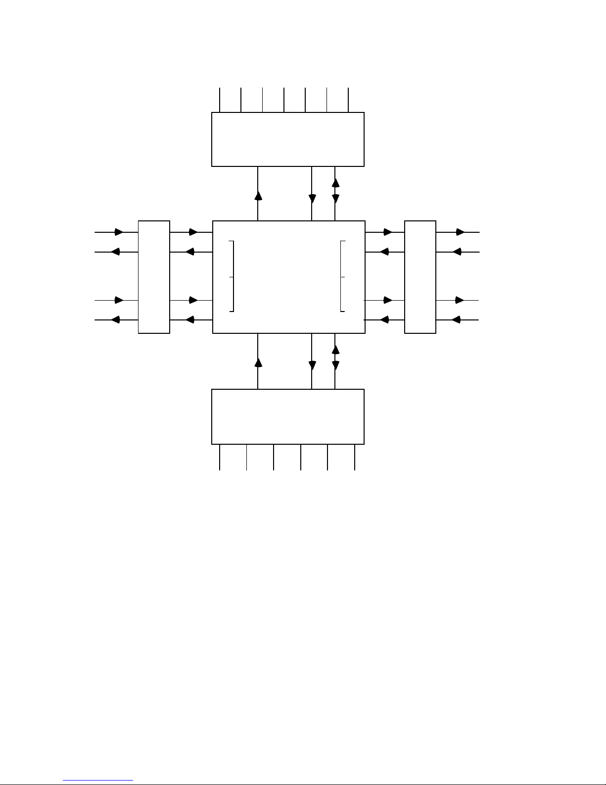
The 3200 is divided into four sections called ports 1, 2, 3 and 4. Each port
can be cross-connected to any other port. Ports 1 and 2 each have one
physical card slot, and 3 x 32 timeslot backplane busses allocated to them.
In Port 1 these backplane streams are referred to as P1, S1 and S2 for
configuration purposes. In Port 2 these backplane streams are referred to
as P2, S3 and S4 for configuration purposes. When a Dual LIU or Dual
Nx64Kbit/s card is inserted in to Port 1 or Port 2, they automatically use
S1, S2 or S3, S4 busses in Port 1 and 2 respectively. This allows access for
cross-connection on the system controller of all 4 x 31 timeslots of 4 x
2Mbit/s PCM stream when a Dual LIU is fitted in Port 1 and 2 for
example. When standard channel cards are fitted in Port 1 and Port 2,
they automatically use P1 or P2 busses in Port 1 and Port 2 respectively.
In this case, they have 32 timeslots available for cross connection at the
system controller.
Port 3 has seven physical card slots in a 3200. Port 3 has 1 x 32 timeslot
backplane bus allocated to it which is referred to as P3 for configuration
purposes.
Port 4 has six physical card slots. Port 4 in all chassis has 1 x 32 timeslot
backplane bus allocated to it which is referred to as P4 for configuration
purposes.
Page 13

X723-300151 1-3 Issue 2
A typical system block diagram is shown in Figure 1-1. If further PCM
line interfaces are required, it is possible to fit Dual LIU cards in Ports 3
and 4, with the restriction of 31 timeslot access in each port.
The 3200 chassis can also incorporate up to four 2048kbit/s G.703 to
optical fibre conversion modules. Details of these modules can be found in
the relevant Technical manual for the FOLD.
A Series 3000 multiplexer power supply unit is required to power the 3200
chassis. This is described in Chapter 8 of this manual.
Page 14
X723-300151 1-4 Issue 2
7 CHAN CARD SLOTS
PORT 3
32
Timeslots
P3
CROSS
CONNECT
SWITCH
D
U
A
L
L
I
U
S1
P1
S2
PCM 1
PCM 2
D
U
A
L
L
I
U
S3
P2
S4
PORT 2
PCM 1
PCM 2
P4
6 CHAN CARD SLOTS
PORT 4
32
Timeslots
SIG
SIG
PORT 1
A B C D E F
G
A B C D E F
Figure 1-1 Typical System Block Diagram
Page 15

X723-300151 1-5 Issue 2
1.2 3200 Facilities
1.2.1 Control of the 3200
The system controller supports an RS-232 port for connection to a
standard ASCII VT100 VDU. This is used for local control and
maintenance purposes. Password protection can be used with this port for
increased security.
Two or more multiplexers may be operated in Local/Remote mode where
control of all multiplexers may be carried out from a VDU connected to one
3200, this is termed the 'local unit'. Control of the 'remote unit' is usually
via spare bit capacity in TS0 or by V.28 connections and a suitable data
link between the two units.
The Network Control System (NCS) may be used to control up to 500
nodes in a network, and also provides node to node control and messaging
facilities.
The system control card supports non-volatile battery backed RAM and a
Real Time Clock, with a retention time of approximately 2 weeks for
storage of cross-connect mappings, fault logs etc. In addition an E
2
PROM
is used for long term storage of the multiplexer ‘Mode Instal’ setting. Note
that if the Firmware level is changed, the contents of the RAM may be
lost.
1.2.2 Control Terminal Operating Modes
The 3200 may be set to operate with a wide range of RS-232 terminals e.g.
Wyse 50 compatible VDUs, Teletypes, Personal Computers etc. A Brief
and Verbose operating mode is available.
A menu tree is used to control the set-up and configuration of the
equipment which is normally used in verbose mode displaying all text. In
brief mode, all menus operate normally except for the text output which is
restricted to prompts, and fault numbers during fault reporting. Brief
mode is provided for factory test purposes, or fast access by experienced
users using pre-prepared configuration scripts controlling a
communication package running on a Personal Computer for example.
An 'Install' set-up facility is provided to configure the equipment to suit
each installation. This contains items such as the 'power-on' default
settings, whether the NCS is to be used and other operational parameters.
Page 16

X723-300151 1-6 Issue 2
1.2.3 Configuration
1.2.3.1 Configuration Fields
The 3200 supports Channel, Smart and Management configurations.
Channel configurations cover the set-up of all the channel cards, the Dual
LIUs when fitted in Ports 1 and 2, synchronisation plus the cross-connect
mappings on the system controller.
There are 14 channel configurations which are stored in non-volatile RAM
and edited in an edit buffer. A default configuration is programmed into
the software to ensure a valid fall back configuration is always available.
Any one of the 14 configurations may be selected and run.
Smart configurations are used by smart channel cards to store their
configuration data. This data is produced by the smart card but stored in
the system controller's non volatile RAM. Each smart card can generate 2
or 4 smart configurations. For each channel configuration a smart card
can be instructed to run any one of its configurations.
Management configurations are used to control the routing of the Network
Management data across PCM TS0 not frame word, and to the system
controllers V.28 network ports and management UARTS.
Fourteen management configurations are provided, each can select
different routing options for management data from the PCM TS0 not
frame word on the Dual LIU or V.28 ports on the system controller. A
management bus is used to allow all the cards in the system to exchange
management data. The management routing is controlled by a series of
pre-programmed patchfields on the system controller and Dual LIU, which
may be selected to provide the required configuration.
1.2.3.2 Equipment Map
A feature of the 3200 is the 'Equipment map'. This is provided to allow the
equipment to register which channel cards are fitted. In addition, the
equipment map is used to raise an alarm if a mapped channel card is
removed or replaced with an incompatible card. Channel Cards which are
not mapped in have fault reporting suppressed by the system controller
but will still function.
Page 17

X723-300151 1-7 Issue 2
1.2.3.3 Dual LIU Configuration Options
When fitted in port 1 or 2, the Dual LIU is configured from the channel
configuration options.
The following are selectable for each PCM line:
Multipoint mode: when selected, timeslots are connected directly
between the 2 line interfaces on the dual LIU,
by-passing the cross-connection of the system
controller. This can be useful in minimising
delays in a network. Individually selected
timeslots from either line may be
dropped/inserted to the cross connect switch in
either duplex or multipoint.
Terminal mode: when selected provides two independent PCM
trunks to the cross connect switch.
A/B mode: when selected provides a route protection
scheme for the line signal.
Signalling mode: this selects Channel Associated Signalling
(CAS), or 31 timeslot mode transparent to
Common Channel Signalling (CCS).
Fault logging: unused lines may have their alarms inhibited to
avoid unnecessary fault logging. When
inhibited the fault responses to the line (remote
frame and multiframe alarm bits) will not be
affected.
TS0 routing: it is possible to route the spare bits in TS0
either to the management patchfield or to the
cross-connect switch to provide management
routing and Remote alarm bit routing.
PCM Bypass: this allows the Dual LIU to be taken out of
service by activating the bypass relays on the
I/O adaptor. This facility may be used where a
standby LIU is fitted but not in service.
CRC4: Provides error performance monitoring using
CRC4. It may be enabled or disabled.
Low error rate threshold: this allows thresholds of 1 in 10
-4
, 1 in 10-5, or 1
in 10
-6
to be used to raise an alarm. Note that
Page 18

X723-300151 1-8 Issue 2
this does not affect the detection of 1 in 10
-3
error rate required for line service monitoring.
1.2.3.4 Synchronisation Options
The Series 3000 can be synchronised to a 2MHz or two 8KHz, known as
8k1 and 8k2, internal clock busses which are generated by certain channel
cards by recovering a phase locked clock from external interfaces. Access
to the 2MHz clock bus is fully controlled by the system controller.
However, access to the 8KHz busses are not. This is controlled by link
selection on the channel cards. Thus, care should be taken to ensure only
one channel card is connected to each of the 8KHz clock busses at any one
time. The Dual LIU supports the 2MHz clock bus which allows the
multiplexer to be synchronised to a PCM stream or external G.703 clock.
A prioritised list may be set up to give a primary sync source plus 4
fallback sources. The lowest priority source is always the internal free-run
oscillator. All clock sources are checked for frequency, and internal timers
may be invoked to avoid spurious switching between intermittent sources.
Sync sources from the PCM line signal recovered timing are also qualified
against various line signal fail options.
Note: A PCM line signal should not normally be used as the sync source if
it has its fault logging inhibited since failure of the line will not be
reported.
1.2.3.5 Alarm Event Options
An 'Alarm Event' may be used to trigger a change of configuration in
response to failure of either the incoming data paths or to a failed channel
card. These are used to provide automatic re-routing of services affected
by any failures.
For each multiplexer configuration each alarm event source can be
programmed to run a different multiplexer configuration, in the event of
failure, allowing recovery plans to be set-up for multiple failures.
1.2.3.6 Configuring Channel Cards
Channel cards in each port are identified by a letter e.g. P1A, (Port 1 card
A), P3G (Port 3 card G). Each channel card can support up to four
independent circuits numbered 1 to 4 e.g. P4D2 (Port 4 card D circuit 2).
Some channel cards can provide eight circuits and circuit allocation is
described in the relevant Equipment Manual.
Page 19

X723-300151 1-9 Issue 2
Cards with only 1 circuit will only support circuit 1, and dual cards will
only support circuits 1 and 2.
1.2.3.7 Timeslot Assignment
Each channel card circuit may be assigned a timeslot(s) from the 32
available in each port stream (P1, 2, 3 and 4).
Each port stream timeslot has associated with it a 'TS control' byte, which
is used to control the gain of the A-D D-A converters on VF channel cards
for setting the analogue interface levels. It is not used on data cards.
Timeslot assignment is not required for a Dual LIU in ports 1 or 2. The
Dual LIU automatically connects line 1 timeslots to S1(3) timeslots, and
line 2 timeslots to S2(4) on a fixed one-to-one basis, i.e. line timeslot 1, 2,
3,......31 to S bus timeslots 1, 2, 3,......31.
1.2.3.8 Circuit Controls
Each channel card circuit supports two 8 bit control ports. These are used
to control operating modes, data rates and loops etc. The settings of these
control ports will vary from card to card.
1.2.3.9 Smart Configurations
Smart cards support 2 or 4 configurations. The channel configuration
maps which configuration any individual smart card will run for each of
the 3200 configurations.
1.2.3.10 Fixed Codes
Fixed codes are used when cross-connection of data and signalling is not
required or not possible e.g. due to line failures etc.
A table of 16 combinations of user programmable fixed data and signalling
codes is maintained. Each source timeslot may call up any one of these
codes to be used to replace its data and associated signalling.
1.2.3.11 Cross Connect Assignments
The cross-connect path may be set up for each outgoing timeslot from the
cross connect block on the system controller. Note all backplane data
streams are terminated or sourced from the cross connnect block on the
system controller. In each case the source stream/port, timeslot, mode,
and fixed code is defined. Alternatively a fixed data mode may be used
without any cross-connections.
Page 20

X723-300151 1-10 Issue 2
Cross-connection modes supported are:
Simplex: for uni-directional and broadcast data.
Duplex: for bi-directional data.
Multipoint: for point to multipoint services.
To 'undo' a cross-connection it is necessary to allocate fixed data to the
outgoing timeslot. If the connection was in duplex it is necessary to
individually allocate fixed data to each outgoing timeslot, this is because a
duplex connection, for example P3, TS 1 to P4, TS2 sets up 2 simplex
connections for the two outgoing timeslots, P3 TS1 to P4, TS2 and P4 TS2
to P3 TS1.
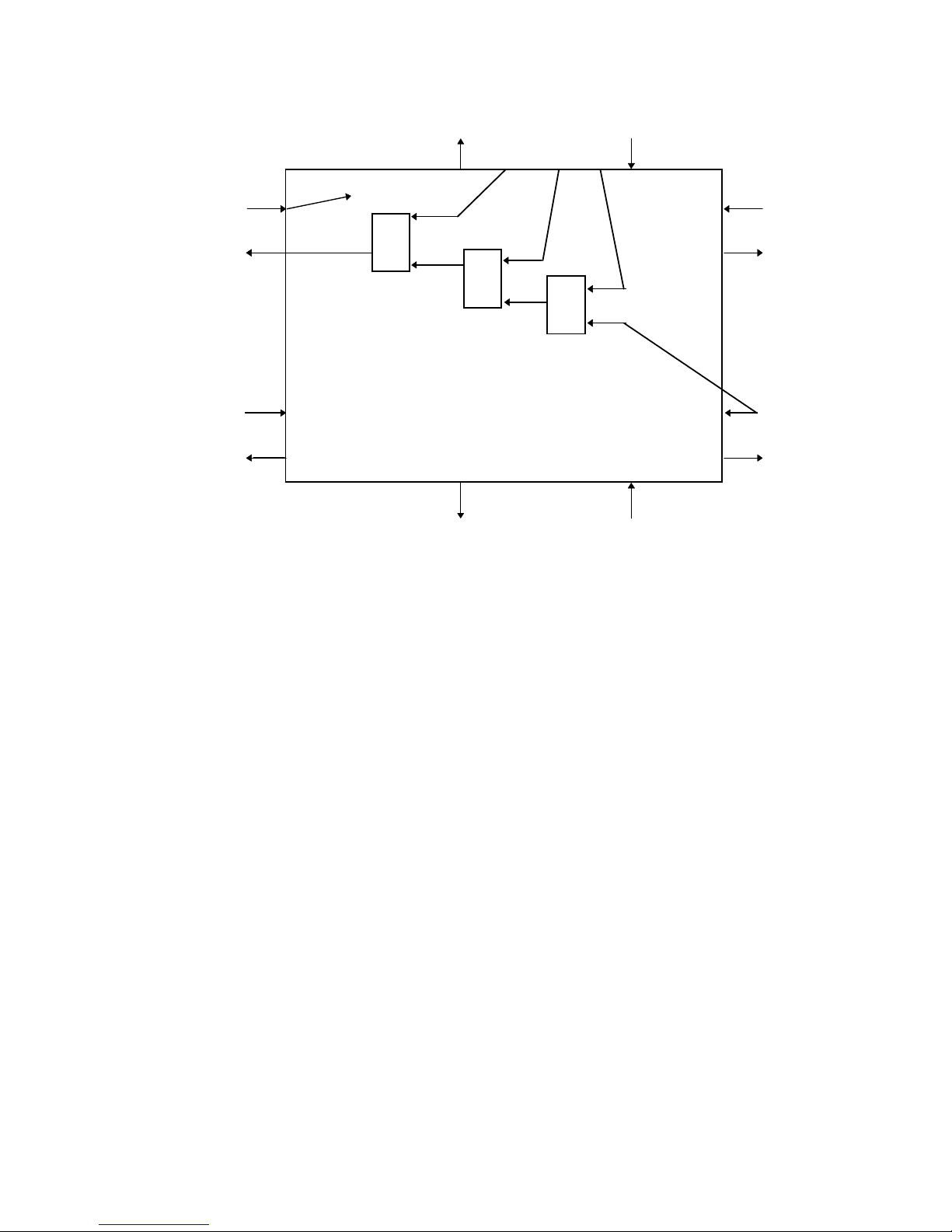
Multipoint allows timeslots from Port 3 (P3) to be 'AND'ed together with
incoming data from any backplane stream, the result is then inserted into
the outgoing backplane stream. This allows timeslots, hence circuits that
support Multipointing, to be cascaded together such that all of them can
insert and drop data from one timeslot. The end of the chain is referred to
as the master and is connected to many slave cards. The master usually
broadcasts data to all slaves. For correct operation, only one slave may be
active i.e. inserting data at a time. While inactive, the slave should insert
'all ones' towards the ‘AND’ gate, thereby allowing data from the active
slave to pass through.
Currently, multipoint cards exist for X.21, Dual V.24 and 2/4 wire voice
circuits. For multipointing to operate a channel card must
NOT be fitted in
port 1; it may be fitted with a Dual LIU or left empty.
Programmable fixed codes are not available for multipoint mode. In these
cases an 'all ones' data pattern will be generated under fault conditions in
each timeslot affected.
Page 21
X723-300151 1-11 Issue 2
123
TS1
TS
S1
S2
*
* Incomin
g
timeslot broadcasts
to all source timeslots.
PORT 4
&
&
&
TS1
S3
To/From
Master
Slave(s)
S4
Slave(s)
PORT 3
Figure 1-2 Typical Multipoint Configuration
1.2.4 Fault Reporting
The 3200 has comprehensive fault reporting facilities. All faults are
logged as messages in a fault store (capable of storing the last 64 faults) to
show the fault history, as well as being held in an active faults list to show
current faults.
Fault messages from smart channel cards will also appear in the fault
store, however the smart card also maintains its own active fault list.
Smart channel cards also control the system controller alarm relays.
Fault stores may be accessed locally by the RS-232 port, or remotely with
the NCS.
All faults have associated alarm LED, and relay actions. The alarm relay
responses can be inhibited by the user acknowledging the alarms with
'Receive Attention' facilities.
Smart channel card faults have a separate 'Receive Attention' facility.
Each fault has an associated fault level, which is used by the NCS to
process network faults, and is not available for display at the equipment.
Page 22

X723-300151 1-12 Issue 2
Fault messages may be displayed directly on the local RS-232 terminal as
the faults occur, or an Alarm Service Request (ASR) mode may be selected.
In ASR mode, fault messages are not automatically displayed, instead an
ASCII BELL character is sent to the terminal every minute until the user
manually requests the new fault messages to be displayed. A printer may
be attached to the terminal to print out the faults as they are displayed.
Fault reporting from channel card circuits may be inhibited with a menu
facility, or by removing the channel card from the equipment map which
will inhibit all fault reporting for that card.
1.2.5 Real Time Clock
The 3200 is equipped with a Real Time Clock. This is used to time and
date stamp fault reports and also to log any messages received from the
NCS.
A timed event facility is provided. This facility allows the 3200 to
automatically change configuration at pre-determined time points,
allowing, for example, voice by day, data by night operation. The time
points may be on a weekly or daily basis over a 365 day period with the
provision to program up to 32 different event changes.
1.2.6 Maintenance Facilities
The 3200 supports comprehensive maintenance facilities as follows:-
Current Configuration and Channel Card Status Display
Each non Smart channel card circuit supports two 8 bit status ports.
These are used to indicate the channel card fault status, card identity code
and set -up. These ports can be useful in identifying the nature of any
active faults.
All configuration parameters may be displayed using the 'Configuration'
menu and in the 'Maintenance' menu, status port values for the channel
cards along with the current sync source and configuration running may
be displayed.
Set and Display Data
Any outgoing timeslot, or its associated signalling, may be set to a user
defined code, and any fixed incoming data or signalling may be displayed
on the local terminal. These are powerful facilities designed to easily test
circuit integrity in conjunction with various loopbacks.
Page 23

X723-300151 1-13 Issue 2
Display Peak Codes
The data display can only display fixed unchanging data patterns which is
therefore not suitable for checking analogue encoded circuits. A 'Peak
codes' display allows the digital code of an analogue signal, and its
equivalent power level to be displayed for any incoming timeslot.
The circuit must be coded to CCITT G.711 A law for this to operate
correctly.
Loopbacks
Various loopback facilities are provided to aid circuit testing.
Local loops; loop the PCM line signal back to the 3200.
Incoming loops; loop the PCM line signal back to the line.
Timeslot loops; loop individual timeslots back to their source.
Circuit loops; activate loops on data channel cards. Generally these are bi-
directional loops to CCITT. X.150
1.3 Mechanical Description
The 3200 is housed in a 19 inch 6RU chassis assembly. The chassis is
fitted with a front panel which is designed to give protection against
electrostatic discharge and should be fitted at all times when the
equipment is in service. The 3200 requires an external power shelf, the
3000 redundant power supply shelf, which is housed in a 19 inch 3RU
chassis.
No electrical connections are required to the front of the unit during 'in
service' operation. Access is provided to the local V.24 port via a covered
cut out in the front panel. Two windows in the front panel allow viewing
of the equipment status LED indicators of the System Controller(s).
Page 24
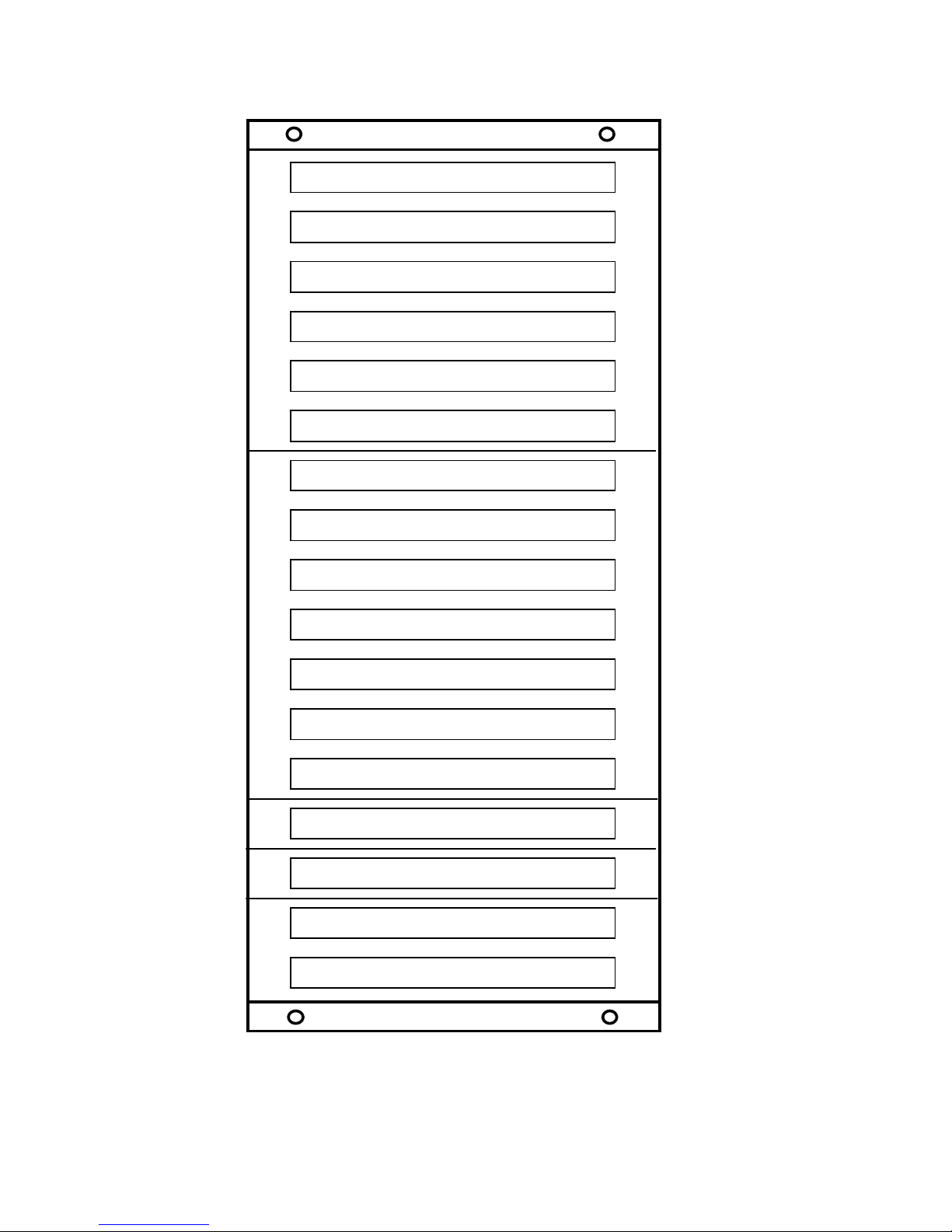
X723-300151 1-14 Issue 2
CHANNEL CARD PORT 4F
CHANNEL CARD PORT 4E
CHANNEL CARD PORT 4D
CHANNEL CARD PORT 4C
CHANNEL CARD PORT 4B
CHANNEL CARD PORT 4A
CHANNEL CARD PORT 3G
CHANNEL CARD PORT3F
CHANNEL CARD PORT 3E
CHANNEL CARD PORT 3D
CHANNEL CARD PORT 3C
CHANNEL CARD PORT 3B
CHANNEL CARD PORT 3A
DUAL LIU PORT 2
DUAL LIU PORT 1
SYSTEM CONTROL (Main)
SYSTEM CONTROL (Standby)
Figure 1-3 Front View of the 3200 Chassis (Typical Configuration)
Page 25
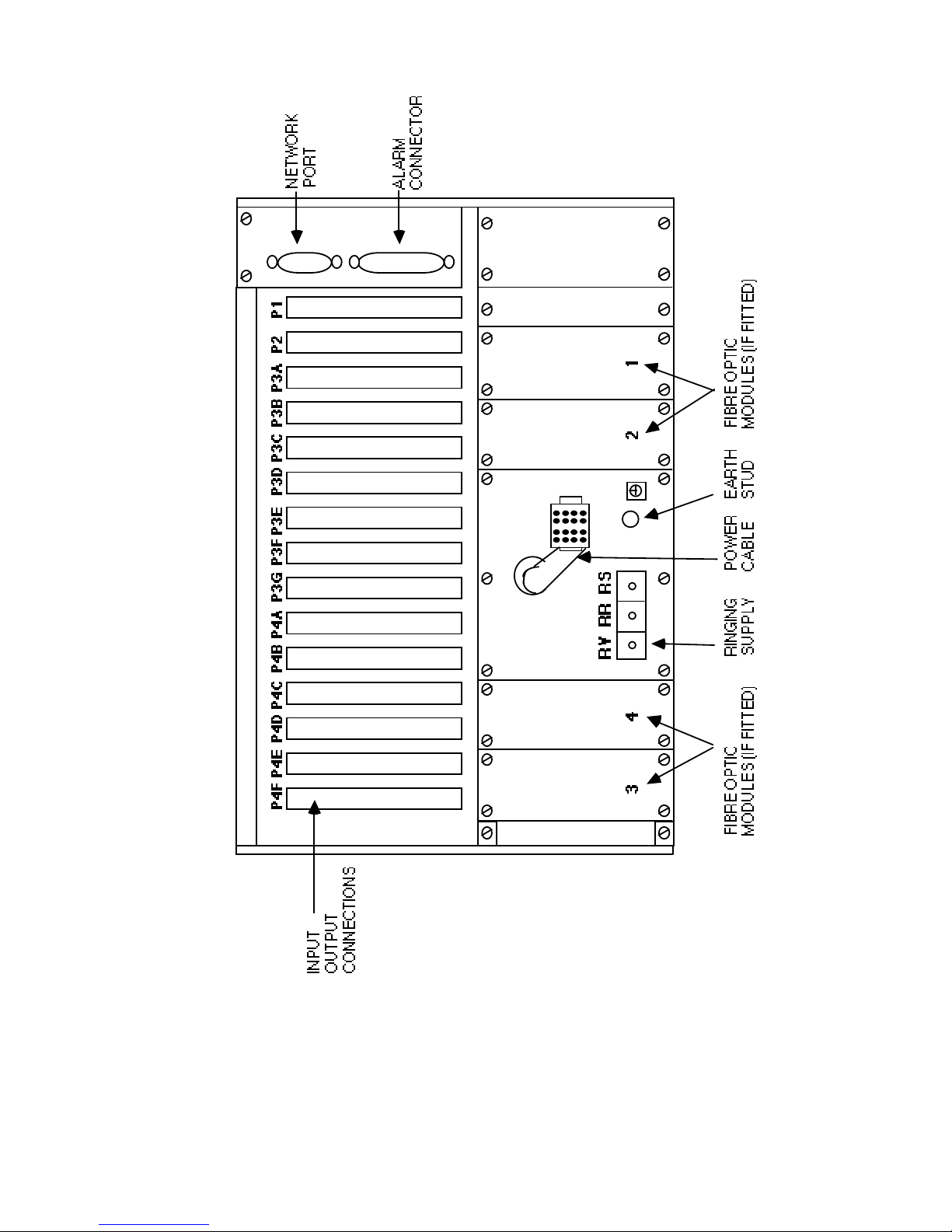
X723-300151 1-15 Issue 2
Figure 1-4 Rear View of the 3200 Chassis
Page 26

X723-300151 1-16 Issue 2
With the front panel removed the chassis provides for the mounting of up
to 17 printed circuit boards. The extreme two left hand positions are for
system control cards. These are marked S<SYS (Standby) and
CON>M (Main).
All input/output connections to the channel cards are made via connectors
on the rear of the unit. These connectors are designed to be optionally
fitted with a universal I/O adaptor (DT280) or DIN 41612 connectors (See
Section 2.2.6).
Up to 15 channel cards may be fitted in the positions marked P1, P2, P3A
to P3G and P4A to P4F. The rear of the unit provides for the fitting of
modules on the lower half of the chassis by removing blank panels. Four
positions are dedicated for the use of fibre optic line driver modules.
Front and rear views of the equipment are shown in Figures 1-3 and 1-4
respectively.
Power is supplied to the chassis via a flying lead and this connects to the
3000 3RU power shelf mounted either above or below the 3200 chassis. A
terminal block is fitted to this panel for the connection of an external
ringing supply (See Section 2.2.9). Two connectors are mounted on the top
right hand rear of the unit. The top connector, a 9 pin D-type, is used for
V.28 Network Management (See Section 2.2.7). The lower connector, a 37
pin D-type, is used for Alarm inputs Control outputs and Alarm relay
contacts (See Section 2.2.4).
1.4 Specifications
1.4.1 Common Equipment
Complies with the relevant sections of:
CCITT G.703, G.704, G.706, G.732, G.736, G.823 (Blue Book).
BS6527 1988 Class A ) (Emissions)
EN55022 ) " "
IEC801 Part 2 Level 3 ESD (8kV)
IEC801 Part 3 Level 3 narrow-band susceptibility (10V/m)
IEC801 Part 2 Level 2 electrical fast transients/bursts (1KVAC Power,
0.5kVDC Power Signal and Control)
Note: I/O adaptors DT280 plus I/O blanking panels must be used for
EMC compliance.
Page 27

X723-300151 1-17 Issue 2
1.4.2 Dual LIU Line Signal Characteristics
Line Rate: 2048kbit/s
Stability: ±25ppm over 5 years when free running
Line Code: HDB3
Transmit Signal Level: ±2.37V ±10% (75 ohms)
±3V ±10% (120 ohms)
Receive Signal Level: 0 to > 6dB line loss
Line Interface: 75 ohms unbalanced: BNC Coaxial
120 ohms balanced: 9 way 'D' Type connector
Jitter Transfer
When a Dual LIU (DTE241) recovered 2048 kHz timing signal is selected
as the system timing source, the jitter transfer from input to output does
not exceed the following limits:
20 dB/Decade
Jitter
Gain
(dB)
0
-25
5 10
178
100k
Frequency (Hz)
Power Consumption
The unit is powered by the 3000 power supply shelf mounted external to
the 3200 chassis. See Chapter 8 of this manual for full details.
One System Controller with one Power Supply Unit. 30 Watts
Two System Controllers with one Power Supply Unit. 36 Watts
One System Controller with two Power Supply Units. 51 Watts
Two System Controllers with two Power Supply Units. 57 Watts
Plus the power consumption of the Dual LIU cards and other channel
cards fitted (See relevant card manuals).
Alarms: 37-way D-Type plug
Alarm Outputs
Prompt: Isolated changeover relay contacts
Page 28

X723-300151 1-18 Issue 2
Service: Isolated changeover relay contacts
System: Isolated changeover relay contacts
Alarm contact rating 1A @ 50VDC (Resistive) 50VA
External Status Inputs:
5 external status inputs are provided:
Characteristics:
General purpose inputs
Active: -60VDC < input voltage < 0.8VDC (Generally 0V)
Inactive: 1VDC < input voltage < 5VDC or open circuit
The external equipment must be capable of sinking 0.25mA when applying
0V, and 63mA when applying -60VDC.
External Control Relays
4 Relays are available for the control of external equipment. These
provide isolated changeover contacts:
Contact rating: 0.4A @ 125VAC
2A @ 30VDC
External Ringing Supply:
Frequency 17-50Hz
Ringing Voltage 50-150VAC RMS with station DC supply offset (-48V)
Ringer Start O/P Open collector WRT - station supply (-48V)
Max current = 50mA
NOTE: Any external ringing supply connected to the equipment must
conform to BS6301.
Local Port:
V.24, RS-232 (9 pin D-type connector)
(No handshaking)
Page 29

X723-300151 1-19 Issue 2
Network Port:
Four V.28 inputs (9 pin D-type connector)
Four V.28 outputs
Gain
The gain through the system to or from the channel interface backplane
connector for a channel containing a voice encoded signal is fixed at 1.
Refer to the relevant VF channel card manual for gain contributions
attributable to the channel card.
Quantisation Distortion
The quantisation distortion through the system to or from the channel
interface backplane connector for a channel containing a voice encoded
signal is 0 qdu. Refer to the relevant VF channel card manual for the
quantisation distortion attributable to the channel card.
Page 30
X723-300151 1-20 Issue 2
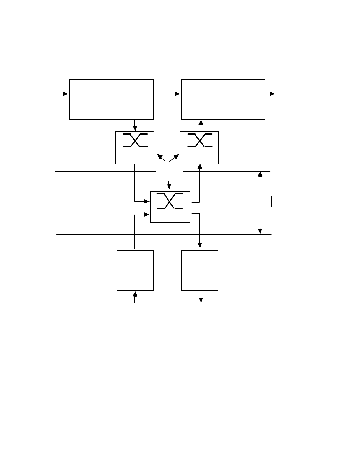
Delay
The delay through the system may be calculated from the following
diagram:-
Min 12 µs
Typ 98 µs
Max 184 µs
INPUT LINE INTERFACE
CROSSPOINT
MT 8980
Min 8 µs
Typ 125 µs
Max 133 µs
CROSSPOINT
MT 8980
CROSSPOINT
MT 8980
Port 3/4
Only
Port 3/4
Only
CODEC
MT 8965
270 µs
MT 8965
CODEC
210 µs
CHANNEL
CARD
DTE 90/91
SYSTEM
CONTROLLER
DUAL LIU
2048 kbit/s 2048 kbit/s
OUTPUT LINE INTERFACE
9 µs
DTE241
For delays attributable to
other line interface cards
see relevant technical manual
Backplane
Interface
VF input VF Output
Channel card shown is for example only. Refer to the relevant channel interface card manual for delays
attributable to other VF cards and data interfaces.
Mechanical:
Height 266mm
Width 485mm
Depth 385mm
Weight Max 20kg (Fully loaded)
Page 31

X723-300151 1-21 Issue 2
Environmental:
Storage temperature: -20
o
C to +50oC
Operational temperature: 0
o
C to +50oC
Humidity: 5 to 95% non condensing
1.5 Product Codes
The following code numbers are applicable to the 3200 equipment:
3200/002: 3200 Multiplexer complete with system control card and alarm
board
DTE221: System Control Unit(added to 3200/002 makes unit redundant
management)
DTE241: Dual 2048 Line Interface Unit
DT315: Dual 2048 LIU I/O Adaptor 75 ohms
DT316: Dual 2048 LIU I/O Adaptor 120 ohms
3000/001: 3200 power shelf 115/230VAC
3000/002: 3200 power shelf 48 Volts
DT106: 115/250 AC PSU
DT107: 48 Volt PSU
Note: Both power shelves are equipped with one PSU as standard
Page 32

X723-300151 1-22 Issue 2
.
Page 33

X723-300151 2-1 Issue 2
2 Installation and
Commissioning
2.1 General
Installation and commissioning of the equipment consists of carrying out
all necessary work prior to configuration for network transmission
requirements. Follow Section 2.2 for physical connections noting
particularly the cabling requirements for the PSU alarms (2.2.4).
Follow Section 2.3 for Link and Switch settings noting in particular the
battery link (2.3.1). Check the Dual LIU and I/O adaptor link settings
(Section 3.1.5). Do not switch on until all cabling is in place, in particular
the earthing, and all links are correctly set.
Control Terminal Operation
A control terminal will be required for initially setting up the multiplexer.
The 3200 is controlled by the local control port, an RS-232 serial interface
on the front of the system controller, the range of baud rates and parity for
which are detailed in Table 2-5. The interface caters for XON/XOFF
protocol.
Remote operation of the 3200 is also possible and this is covered under
Remote Control in Section 5.5.
On power up, if configured for local control, the 3200 will output Self Test
information messages then a prompt and wait for the user input line.
User input is not case conscious.
User input lines are terminated by carriage return (CR) and no actions
will be taken until CR or other special characters have been entered.
Lines may be aborted before CR is entered by entering ESC or !. All lines
will be acknowledged by the 3200 by returning at least a prompt character
which will indicate the result of the previous input and that the 3200 is
ready to accept another line.
All 3200 commands are based on a menu selection scheme. The menu
structure is in the form of a tree with a single 'root' menu which branches
Page 34

X723-300151 2-2 Issue 2
to various 'sub-trees' and eventually to 'leaves' which are individual
commands. Selection of the route through this tree from the current
menu is by entering selection characters as defined in each menu along
the way. These selection characters may be entered singly resulting in
prompts at each menu level, or as a complete string. Most commands will
also require parameters, some will require multiple lines of parameters
which can either be appended to the selection characters or in following
input lines in which case the unit will prompt for them as required.
2.1.1 Modes of Operation
The 3200 local control system can operate in four modes, 'Brief' or
'Verbose' and 'Echo' or 'No Echo'. On initial power up the operating mode
will default to the 'Verbose' + 'Echo' mode. which can be changed by menu
commands if required. Verbose mode
MUST be used with the NCS.
Brief/Verbose
In verbose mode the local control port will provide full prompts for menu
selection and parameter entry, the output from commands which display
information will also contain some explanatory text. In brief mode, all
menu and parameter prompt texts are suppressed and output information
will have any explanatory text suppressed. Brief mode is provided for
factory test purposes, or fast access by experienced users using preprepared configuration scripts controlling a communication package
running on a Personal Computer for example.
Echo/Noecho
If echo is enabled, all normal characters received will be echoed. Lower
case characters entered will be echoed in upper case.
2.1.2 Commands and Control Characters
Prompt Characters
The 3200 will always prompt when it requires another input line, in
verbose mode this will consist of text indicating possible selections of
parameters required followed by a special prompt character. In brief
mode, only the prompt character will be displayed. There are three
possible prompt characters as shown below:
> This is the normal prompt when more input is required
Page 35

X723-300151 2-3 Issue 2
*
> This prompt is given after a command has successfully been
completed
?> This prompt is given after an invalid input line which may be due
to an invalid menu selection, or an invalid parameter for a
particular command, in this case an error message would have
already been displayed in brief and verbose modes.
2.1.3 Special Input Control Characters
The following input characters have special meanings:
Esc Aborts the current input. If entering parameters, the current
command is aborted, if selecting from a menu the current
menu is aborted and its parent menu becomes the current
menu. 'Esc' will always insert a CRLF and the 3200 will
prompt for another input line.
! This character is primarily intended for computer control of the
unit, its function is similar to 'Esc' but the root menu becomes
the current menu. If echo is enabled, the character is echoed.
Ctrl+S <XOFF> Instructs the unit to cease serial data transmission
Ctrl+Q <XON> Instructs the unit to re-commence serial data
transmission
Ctrl+X Used as a means of escape from the control of a remote unit.
Sending Ctrl+X from the console will cause the unit to transmit
XOFF to the remote unit and return control to the local unit.
All other characters, including Ctrl+W, are considered to be menu
selections or parameters, all lower case input will be forced, and if
enabled, echoed in upper case.
2.1.4 General Conventions for Verbose Prompts and Messages
In verbose mode the 3200 provides useful prompting information for menu
selection and parameter entry, these prompts follow some general
conventions.
Where possible all prompts will be on a single 80 character line ending
with one of the special prompt characters. If used with a terminal, input
from the user will be echoed following the prompt on the same line.
For menu selection the prompt will consist of a list of options separated by
the | character. The options will be displayed in lower case with the
Page 36

X723-300151 2-4 Issue 2
character required to make the selection in upper case, where possible it
will be the first character of the option name.
2.2 Installation
This equipment must only be installed by suitably qualified service
personnel. Please ensure you read the statutory notices in the preface
of this manual before proceeding.
2.2.1 Unpacking
Check for any physical damage on receipt of the equipment and advise
Cray Communications by contacting our Customer Service Department
and the carrier immediately if any damage is found. Retain the packing
material in case future transportation is required.
2.2.2 Mounting
The unit should be mounted in a standard 19" rack or in a suitable
compatible equipment housing. Side supports should be fitted to each side
of the rack to aid mounting and to prevent undue strain on the front end
angle brackets. Sufficient clearance should be allowed to give adequate
ventilation. A means of preventing flaming material reaching the floor in
the event of fire should be provided underneath the 3200 chassis.
When using a power shelf configured for redundant PSU operation, it is
recommended that a 1RU space is maintained between the 3200 and the
power shelf, this is to aid cooling by improving air circulation within the
rack.
Note: Consideration should be given to forced air cooling of the power
supply. Refer to the 3000 Power Supply Equipment in Chapter 8 for
details.
All connections are made via the rear of the unit. Sufficient clearance is
required for the fitting of connectors and cable routing.
CAUTION:
As the weight of a fully equipped chassis can be up to 20kg, it is advisable
to remove all channel cards before inserting or removing the chassis from
a rack. Incorrect handling of a fully equipped chassis could result in
undue strain on the chassis tie bars. Observe electrostatic handling
procedures.
Page 37

X723-300151 2-5 Issue 2
2.2.3 Power Connections and Earth Bonding
The 3200 should be wired to the power shelf using the flying lead
protruding from the rear of the unit. This lead will connect directly to the
socket situated on the rear of the power supply shelf. The power supply
shelf may be situated above or below the 3200.
Earth Bonding
Correct earth bonding of the chassis is important if the equipment is not
to be affected by electrostatic discharge (ESD) or other environmental
interference sources. A separate earth connection must be made from the
chassis earth stud to the station earthing system. The resistance of this
connection must not exceed 0.03 ohms which should be checked using an
earth bonding tester. Note that if the earthing arrangements are via a
rack earth bar or rack framework, the total earth resistance must not
exceed that stated above.
2.2.4 Alarm and Control Wiring
The alarm outputs, control outputs and external status inputs are
accessed via a 37 way 'D' Type connector. The alarm and control output
change over contacts are isolated. The N/C and COM contacts should be
used to provide a short circuit loop during alarm conditions. See Table 2-1.
An alarm is active when the relays are de-energised, hence when power is
removed from the unit all alarms become active.
The external status inputs are '0V sensing' and designed to operate with
TTL level inputs. 0V is the alarm condition with +5V or open circuit being
the non alarm state. See alarm specifications in section 1.
External status lines 2 to 6 may be connected to co-located equipment to
monitor, for example, alarm relay status. The external relay contacts may
be wired to control external equipment.
Observe BS6301 safety requirements when making any external
connections.
Page 38

X723-300151 2-6 Issue 2
37-way D-type Plug Pin No. Function
1,6,7,20,24,25 0V Connections
2 External status 2
21 External status 3
3 External status 4
22 External status 5
4 External status 6
23 PSU A Fail
5 PSU B Fail
8 COM }
26 N/O } System Alarm Relay
27 N/C }
28 COM }
9 N/O } Service Alarm Relay
10 N/C }
11 COM }
29 N/O } Prompt Alarm Relay
30 N/C }
31 COM }
12 N/O } Receive Attention
13 N/C } Relay
14 COM }
32 N/O } External Relay 1
33 N/C }
34 COM }
15 N/O } External Relay 2
16 N/C }
17 COM }
35 N/O } External Relay 3
36 N/C }
37 COM }
18 N/O } External Relay 4
10 N/C }
Normally Closed (N/C) is the de-energised/alarm state.
Table 2-1 Alarm Connector Pin Connections
PSU A and B fail inputs should be connected to the power shelf when
configured for redundant PSU operation as follows:
3200 37-way Power unit 9-way
D-type Connector D-type Connector
Pin 23 (PSU A Fail) Pin 1
Pin 5 (PSU B Fail) Pin 2
Page 39

X723-300151 2-7 Issue 2
2.2.5 PCM and G.703 Clock Connections
The Dual LIU utilises either the DT315 or DT316 I/O adaptor for
interfacing to 75 or 120 ohm lines respectively. These plug into the I/O
connectors shown in Figure 1-3.
The DT315 has 75 ohm BNC unbalanced connectors, with the 'screen' of
the transmit connector earthed by mechanically securing it to the body of
the I/O adaptor. The 'screen' of the receive connector is isolated from the
body of the I/O adaptor with insulating washers.
If it is required to earth the 'screen' of the receive connector instead of the
transmit, then it is necessary to re-assemble the I/O adaptor with the
insulating washers fitted to the transmit connector.
The DT316 has PCM connections using two 9-way D-type connectors. The
transmit O/P signal is present on pins 5 and 9, and the receive I/P signal
is on pins 1 and 6. The cable screen should be connected to the body of the
connector.
The clock signals are presented on a separate 9-way D-type connector with
the transmit clock on pins 4 and 8, and the receive clock on pins 2 and 7.
The cable screen should be connected to the body of the connector.
The Dual LIU I/O adaptors are equipped with bypass relays that will, on
power down or under firmware control, bypass PCM line 1 to line 2, and
Clock in to Clock out. This action may be inhibited for the PCM signals
only by fitting links LK1-LK4 on the I/O adaptor to positions 2-3.
2.2.6 Data Wiring
The connectors on the back of the chassis allow for data connection to
channel cards. Data connectors must be inserted to the corresponding
connector for the channel card positions. i.e. a channel card in P3A must
have its data connector inserted in to the corresponding connector marked
P3A on the rear of the unit. The connector type is a 96-way DIN 41612
Type C plug (Male).
The pin allocations for channel cards vary from card to card. A detailed
pin out can be found in the relevant channel card manual.
A universal I/O adaptor DT280 is available to convert the 96-way DIN
41612 Type C plug to a 50-way Amphenol Female Connector.
Page 40

X723-300151 2-8 Issue 2
This adaptor provides additional screening and must be used where
compliance to EMC specifications are required. The pin connections are
shown in the relevant channel card manual.
2.2.7 Network Management Connections
Network management is connected to the unit via a 9-way D-type socket.
This port uses V.28 signal levels. The COM signals on the port are
defined by the System Controller Patchfield. Note: it is possible to redirect the local port VDU access to the Network Port using these
Patchfields.
Pin No. Function
1 COMo1
2 COMo2 OUTPUTS
3 COMo3
4 COMo4
5 COMi1
6 COMi2 INPUTS
7 COMi3
8 COMi4
90V
Table 2-2 Network Port Pin Connections
2.2.8 Local Port Connections
Local port (DCE) access is provided via a 9-way D-type socket situated on
the front of the system controller PCB. Access can be gained to this
connector via a covered cut out in the front panel.
Pin No. Function
1NC
2 Transmit Data (INPUT)
3 Receive Data (OUTPUT)
4 Control (DTR)
50V
6NC
7 Control (RTS)
8NC
9NC
Table 2-3 Local Port Pin Connections
The control outputs are permanently wired to the 'ON' condition.
Page 41
X723-300151 2-9 Issue 2
Warning: Care should be exercised to ensure that the terminal being
connected to the multiplexer local port shares a common earth with the
multiplexer, otherwise permanent damage may result.
2.2.9 Ringing Voltage Connections
When using any 2-wire loop disconnect subscriber interface card, an AC
ringing supply will be required.
The ringing voltage may be supplied by an internal ringing generator card
DT579, or from an external supply connected to a terminal block on the
rear of the equipment. If an internal ringer is used, this will require a 48VDC supply even on a mains powered chassis. This supply is switched
and fused on the 3000 power supply unit O/P panel.
The ringing generator card supplies ringing voltage for up to ten
telephones of REN = 1. Ringing generators cannot be paralleled to
increase output drive, therefore the 3200 backplane is split into 4 sections
to allow more than one ringer to be fitted if required, e.g. chassis equipped
with more than 10 subscriber circuits. Links must be positioned correctly
to disconnect the sections otherwise damage to the ringing generators will
result.
In order to select which supply is used, links are positioned on the
backplane to select the supply for each section, hence up to four internal
ringing generators may be fitted each supplying an individual section.
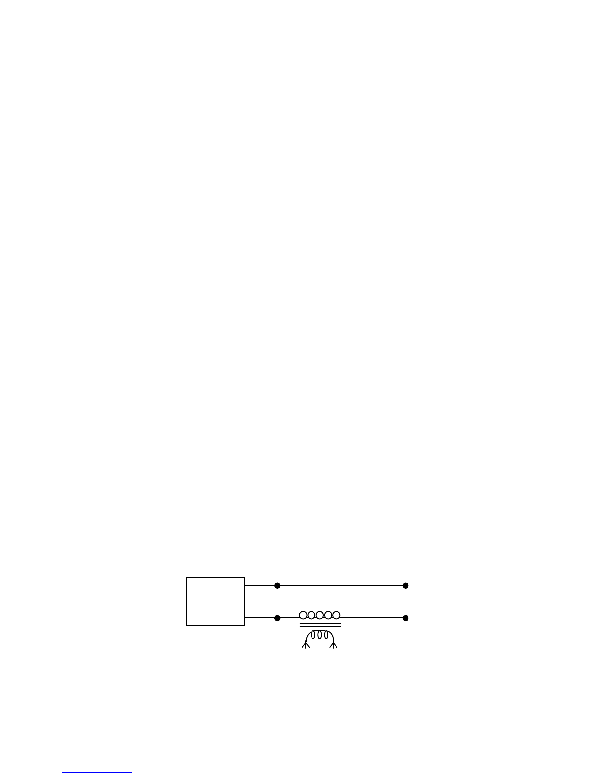
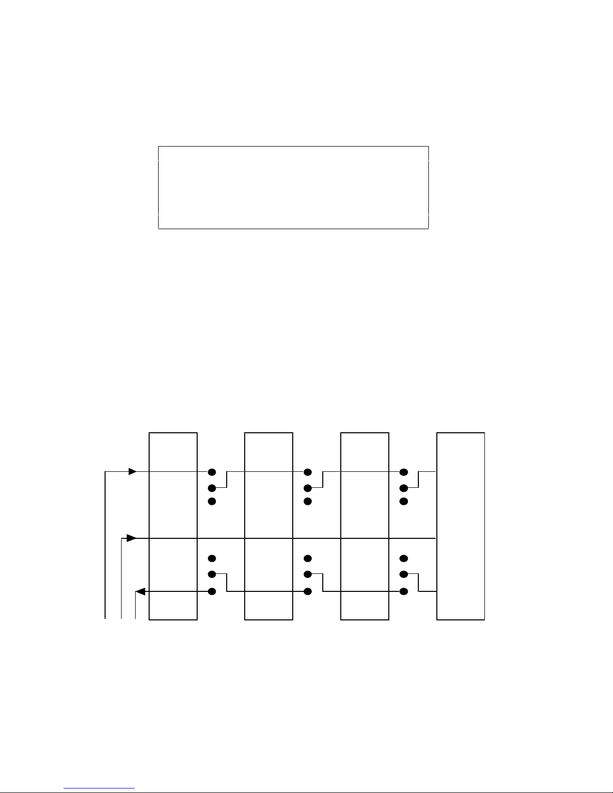
Any external ringing supply must be battery backed. The ringer supply
terminal block connections are as follows:
RV - ringing voltage
RR - ringing return (common to all sections)
RS - ringer start
The ringing supply must be across RV and RR. The RR terminal must be
connected to the station battery 0V.
MUX
0V
-48V
50-125v RMS
AC source
RR
RV
Figure 2-1 External Ringing Supply Connections
Page 42
X723-300151 2-10 Issue 2
The RS terminal is used to indicate when ringing voltage is required to
switch on an external ringer, it is an open collector O/P. When RS = 0V
(battery +ve) then ringing voltage should be present on RV and RR. The
RS terminal does not have to be connected, ringing voltage may be present
continuously across the RV and RR terminals.
Section Backplane Link
RV RS
PORT 1 - PORT 3C LK5 LK6
PORT 3D - PORT 3G LK1 LK2
PORT 4A - PORT 4C LK3 LK4
PORT 4D - PORT 4F - -
Table 2-4 Ringing Voltage Isolation Links
The section of the backplane, port 4D to port 4F, is always connected to
the terminal block. If an internal ringer is used, no connection should be
made to the terminal block at the rear of the equipment.
The perspex cover on the terminal block must be fitted when an internal
ringer is fitted as ringing voltage will always be present across the
terminals. Note that ringing voltage will also be present on Pin 25a of the
DIN 41612 I/O connector for each port.
The backplane sections are as shown below.
RV
RR
RS
PORT4D
TO
PORT4F
PORT4A
TO
PORT4C
PORT3D
TO
PORT3G
PORT1
TO
PORT3C
LINKED
LK3
SEPARATE
LK1
SEPARATE
LK5
SEPARATE
LINKED LINKED
LK4
SEPARATE
LINKED
LK2
SEPARATE
LINKED
LK6
SEPARATE
LINKED
Figure 2-2 Ringing Voltage Backplane Links
Page 43

X723-300151 2-11 Issue 2
2.3 Commissioning
2.3.1 Link and Switch Settings
The 3200 may be controlled via its local port, a DCE V.24 RS-232 serial
interface. This port is configured by switch SW1 on the front of the
system control card DTE221. Switch SW1 is read at power up and
periodically to allow configuration of the local port to be modified once
powered up. Switches S2 to S8 of SW1 control the setup of local port.
Options available are shown in Table 2-5.
Switch S1 of SW1 allows the operator to communicate locally with a unit
when it is normally operating as a remote unit in Local/Remote mode.
The links on the System Controller should be in the following positions:LK1 2-3
LK2 2-3
LK3 2-3 For normal operation, 1-2 for redundant controller operation
LK4 2-3
LK5 1-2
LK6 1-2
LK7 1-2 RAM backup battery connected. (2-3 = disconnected) *
LK8 2-3
* Note: The unit should
NOT be operated with the battery disconnected.
Switch Closed Open Function
1 Normal Local Local Access
2 1 bit 2 bits Stop bits
3 7 bits 8 bits Data bits
4 Even Odd Parity
5}
6 } Local Port Baud Rate (See Table 2-6)
7}
8 Enable Disable Parity
Table 2-5 System Controller SW1 Switch Settings
Rate S5 S6 S7
150 Closed Closed Closed
300 Open Closed Closed
600 Closed Open Closed
1200 Open Open Closed
2400 Closed Closed Open
4800 Open Closed Open
9600 Closed Open Open
19200 Open Open Open
Table 2-6 Local Port Baud Rate Switch Settings
Page 44

X723-300151 2-12 Issue 2
2.3.2 Redundant System Control Card
A second (standby) system control card may be fitted in the far left hand
(S<SYS) position of the 3200 to provide backup for the main system
controller should it fail. LK3 on both cards must be in positions 1-2 if this
facility is required. The redundant mode of operation is used to protect
against a system controller failure. One system controller will have full
control of the unit (normally the main system controller), while the other
(standby system controller) is ready to take control if the main fails or a
manual change-over occurs. The active system controller copies its
configuration data to the standby unit, allowing the off-line to take control
with minimal disruption to service.
Change-over Criteria
Main to standby changeover will occur automatically when the standby
system controller has indicated that it is operating correctly, received its
configuration information from the main unit, and one of the following
conditions occurs:
1) The main system controller suffers processor failure.
2) The main system controller reports that it has failed. This may
occur when internal self test fails.
3) The main system controller is unplugged.
4) Change-over is requested from the maintenance menu.
Once the change-over has occurred the standby system controller will take
over full control of the unit.
If the main system controller recovers, the new standby system controller
will still retain control of the unit. If the standby system controller fails
after taking control, the main system controller will then regain control.
If network management is being carried out via the rear network port
connector, the chassis must be fitted with an alarm I/O adaptor DT245 to
correctly route the management V.28 signals to the main or standby
system controller.
The green LED on the on-line system controller will be continuously 'On'.
The green LED on the standby system controller will flash.
The red Miscellaneous LED will be lit on the off-line system controller
until it has received all configuration information etc. from the main
system controller. The Miscellaneous LED will also be lit if the standby
card has failed its self test.
Page 45

X723-300151 2-13 Issue 2
Standby Operation
When the standby system controller has received all configuration
information required to take control, it will configure itself and then wait
for control. All configuration and set-up data will be passed to the standby
system controller except for:-
i) Maintenance test information (loops, and set data)
ii) Network messages
iii) Fault logging information
iv) Current sync source
Two menu options are provided under (!MSR) 'Maint' - 'System' 'Redundant':
Off-line Command (!MSR0)
Using the 'Offline' command from the on-line card, will cause that system
controller to be switched off-line and the off-line system controller to be
switched on-line.
If the on-line card is unable to pass control to the off-line card a message
'Offline system controller not responding'
will be displayed and no further action will take place.
If the off-line system controller is not present , the message
'Offline system controller not fitted'
will be displayed to the user, and the original system controller will
remain on-line.
If the off-line system controller is receiving data from the on-line system
controller the following message will be displayed.
'Offline system controller configuring'
The operator should wait for the off-line system controller to finish
configuring, indicated by the Miscellaneous LED on the off-line system
controller extinguishing, and then re-try the 'Offline' command.
Note: Switching from 'Main' to 'Standby' or 'Standby' to 'Main' will cause
a momentary glitch on the external relays.
Page 46

X723-300151 2-14 Issue 2
Inhibit Command (!MSRI)
This command is available to inhibit fault reporting and communication
between the off-line and on-line controllers. This facility MUST be used
before removing an off-line system controller from the multiplexer. If this
facility is not used, removal of an off-line system controller may result in
corruption of data through the multiplexer. The 'Inhibit' condition will
remain for 2 minutes after which time communication and fault reporting
will resume as normal. On re-insertion of the off-line system controller,
the user must wait for the 2 minutes to expire and the card to configure
before they can remove the card again using the above method.
If the off-line system controller is not communicating, the message
'Unable to verify offline system controller inhibited. Corruption could result
upon removal of offline system controller'
will be displayed.
If the off-line system controller is not present, the message
'Offline system controller not fitted'
will be displayed to the user.
If the off-line system controller is receiving data from the on-line system
controller the following message will be displayed.
'Offline system controller configuring'
If the command is repeated within the two minutes inhibition time, the
message
'Offline system controller inhibited for the next XXX seconds'
will be displayed to the user, where XXX is the time remaining that the
system controller will remain inhibited.
Removing and Replacing a System Controller
The following procedure should be carefully followed to ensure correct
operation of the redundant switch at a later date.
i) If the system controller to be removed is the on-line system controller
use !MSRO to change it over to off-line.
ii) On the now ‘on-line’ unit use the !MSRI command and ensure the
message indicating the off-line system controller has been inhibited
for 120 seconds is displayed.
iii) Remove the off-line system controller from the multiplexer.
Page 47

X723-300151 2-15 Issue 2
iv) Refit new system controller.
v) No more change-overs or removals should be attempted until the 2
minutes is completed and the off-line system controller has received
all of its configuration data from the on-line system controller. This is
indicated on the off-line system controller by the top red LED
illuminating while configuration data is being transferred, and then
extinguishing when all configuration data has been passed. If the 2
minute time-out should expire and the off-line controller is then
refitted, it is possible that some data loss will occur.
Note: Removal of a working 'on-line' card in a live system will cause data
loss and may cause a momentary change in the state of the Prompt,
Service, System and External relays.
2.3.3 Switch on Procedures
Connect a VDU, set so as to be compatible with the settings made on SW1,
to the local port. Switch on the multiplexer. On initial power up, the
3200 will automatically enter self test mode. The self test procedure
varies, depending upon the number of system controllers fitted.
Single System Controller operation:
Upon power up the 3200 will carry out a full self test.
Dual System Controller operation:
Upon power up the main system controller will carry out a full self test. If
any part of this self test fails the Standby system controller will take
control. On power up the Standby system controller will carry out an
internal self test and then wait for a change over from the Main system
controller. If the standby self test fails, it will report a failure back to the
Main system controller.
Self Test Mode
The unit incorporates a self test facility which is activated either at power
up or from menu selection and runs for a period of 8 seconds. The test will
set the following conditions:
a) Illuminate all LEDs on the on-line system controller.
b) Set all alarm relays except the System relay.
c) Run a self test configuration.
d) Each LIU fitted will have its relays set to bypass and PCM looped.
e) Sync source will be derived from the free running VCO clock.
Page 48

X723-300151 2-16 Issue 2
On completion the VDU should display 'self test passed' if not it will
indicate failure and list the failed items. The self test will fail if Dual LIU
cards in ports 1 and 2 are not fitted with I/O adaptors.
2.3.4 Initial Multiplexer Set-up
Install the Dual LIU and channel interface cards in the required port
slots.
Connect a terminal to the local port and obtain the Root Menu prompt as
follows:
(P63) Maint | Fault | mOde | Configure | Time | Remote | Smart | closE >
After switching on a new unit or one that is un-configured, it will be
necessary to set certain parameters using a dumb terminal. Carry out the
'Install' procedure under the 'mOde' menu option (see Section 5.3.4)
ensuring that networking is enabled. If required networking can be
disabled for Local/Remote operation after the changes have been saved. In
addition carry out the following:
1) Set the real time clock. (See Section 5.2.2.)
2) Set the calendar. (See Section 5.2.2.)
3) Remove all timed events. (See Section 5.2.3.)
4) Disable alarm events. (See Section 5.4.1.)
5) Install cards into the Equipment Map. (See Section 5.4.17.)
6) Load the default PCM configuration and save into all 14
configurations. (See Section 5.4.2.)
7) Check the active fault log and diagnose and clear any remaining
non PCM configuration faults.
2.3.5 Alarm Indicators
The 3200 has 9 LEDs which are situated on the front of the system
controller PCB. The LEDs indicate any alarm conditions that occur on the
unit. The main functions are listed below with a detailed function for each
LED contained in the fault chart in Section 6.1.1.
Misc Alarm
Port 1 Alarm
Port 2 Alarm
Port 3 Alarm
Port 4 Alarm
Not Primary Sync
PSU fault
Page 49

X723-300151 2-17 Issue 2
System Alarm
Power/Active
All the LEDs are red except for the Power/Active LED which is green.
This LED will be on continuously when the system controller is active,
and will flash if the system controller is the standby card in redundant
operation when equipped. In addition to these alarms, channel cards have
LEDs to indicate alarm conditions, however these can only be viewed by
removing the front panel.
See Section 3.1.8 for a description of the LED indicators on the Dual LIU.
Alarm conditions can be examined via the local port or network port
where an exact description of the fault can be found.
When an alarm occurs the appropriate alarm relay will also be set (See
Table in Section 6.1.6)
Page 50

X723-300151 2-18 Issue 2
.
Page 51

X723-300151 3-1 Issue 2
3 Dual Line Interface Unit
3.1 General
Dual Line Interface Units (DTE241) installed in ports 1 and 2 must be
fitted with DT986/2 or later firmware. When fitted to port 1 or port 2, the
configuration of the Dual LIU is transparent to the user.
The Dual LIU will be listed as a DT310 (base card) in the Equipment map.
The Dual LIU provides an interface to two 2048kbit/s PCM streams. The
PCM electrical signals comply to CCITT recommendation G.703 as either
unbalanced 75 ohm or balanced 120 ohm interfaces. The options of 75
ohms or 120 ohms operation is provided by a choice of I/O adaptor (DT315
and DT316 respectively) which is used exclusively with the DT310 card.
No other 3000 Series I/O adapter must be used as they may result in
damage to the DT310. The Dual LIU also provides an interface to a
2048kHz clock signal, the electrical characteristics of this also comply
with CCITT G.703.
When fitted in ports 3 or 4 the Dual LIU operates as a 'Smart' card which
is covered separately in the operation manual X723-303051 for the Dual
Line Interface Unit and not in this manual.
3.1.1 TS0 'Not Frame Word' Routing
Dual LIU cards fitted with firmware DT986/6 or later have the facility to
connect the TS0 'Not Frame alignment Word' to the cross-connect switch
for routing through the system or to the management patchfield. The
following modes of operation are provided, and these are selected when
configuring the mode of operation for the card in ports 1 and 2.
Modes 2,3,4,6 and 7 of this option require the installation of management
patchfield DT995/E in the Dual LIU to gain access to the Remote Alarm
bit 3.
Not frame words which are dropped/inserted to port (P1, P2, P3, P4)
streams timeslots 0 and 1 may be cross connected to any other timeslots
using the normal cross connect facilities of the multiplexer.
Page 52

X723-300151 3-2 Issue 2
Mode 1 (Default)
The incoming NFW from the relevant line is written
to the relevant patchfield with the Remote Alarm bit
set to a 1. The outgoing NFW is read from the
patchfield and the Remote Alarm bit will be set to a 0
.
This allows the use of patchfield 995/D
Mode 2
This is the same as mode 1 except that the Remote
Alarm bit is not masked and all bits may be used by
the patchfield to give TS0 transparency.
Mode 3
Line 1 - TS0 outgoing will be read from port X TS0.
TS0 incoming will be written port X TS0
Line 2 - will be set as mode 2
Mode 4
Line 1 - will be set as mode 2
Line 2 - TS0 outgoing will be read from port X TS0 .
TS0 incoming will be written to port X TS0
Mode 5
Line 1 - TS0 outgoing will be read from port X TS0.
TS0 incoming will be written to port X TS0.
Line 2 - TS0 outgoing will be read from port X TS1.
TS0 incoming will be written to port X TS1
Mode 6
Line 1 - TS0 outgoing will be read from port X TS0.
TS0 incoming will be written port X TS0
Line 2 - will be set as mode 2
Mode 7
Line 1 - will be set as mode 2
Line 2 - TS0 outgoing will be read from port X TS0 .
TS0 incoming will be written to port X TS0
Mode 8
Line 1 - TS0 outgoing will be read from port X TS0.
TS0 incoming will be written to port X TS0.
Line 2 - TS0 outgoing will be read from port X TS1.
TS0 incoming will be written to port X TS1
X = P1, P2, P3 or P4
Notes:
1. In modes 3 to 8, the outgoing TS0 Frame bit 2 is masked to a 1.
2. In modes 3 to 8, the outgoing Remote Alarm bit consists of port X TS0
Remote Alarm bit logically 'OR'ed with the Remote Alarm bit derived
from the state of the incoming line signal.
3. In modes 3 to 8, the incoming TS0 NFW read from the line signal and
written to the port timeslot will not be masked or added to.
4. In modes 6 to 8, bit 1 (International signalling bit) is forced to a 1 on
the outgoing line signal for use with the DT585.
Page 53

X723-300151 3-3 Issue 2
The following options will be presented whilst configuring each mode of
operation for the Dual LIU, to enable the TS0 routing options to be
selected. The preceding display will depend upon the LIU mode selected.
1 Normal
2 Normal plus Remote Alarm
3 L1 to TS0
4 L2 to TS0
5 L1 to TS0, L2 to TS1
6 L1 to TS0 (DT585)
7 L2 to TS0 (DT585)
8 L1 to TS0 (DT585) , L2 to TS1 (DT585)
TS0 mode 1 >
3.1.2 Clock Recovery and Selection
A recovered 2048kHz clock is available from each of the received PCM
lines and a 2048kHz external clock signal input socket is provided. Any of
these clock sources may be selected by the system controller as the system
clock, and are monitored by the system controller only if they are allocated
in the clock priority list.
3.1.3 Jitter Attenuation
Jitter attenuators are used on the PCM and clock inputs to reduce jitter
on the recovered signals. This improves jitter transfer of the system if the
clock is selected as the system timing source. A two frame input buffer is
provided on each PCM line input.
3.1.4 Frame Structure
The framing structure complies with CCITT G.704 and the card supports
Channel Associated Signalling (CAS) or can be used in 31 timeslot mode
transparent to Common Channel Signalling (CCS). The signalling mode
for each of the two PCM interfaces may be selected independently.
Page 54

X723-300151 3-4 Issue 2
3.1.5 G.703 Clock Output
The timing for the G.703 clock output is sourced from the system clock
(PLL) except under bypass conditions when it is sourced from the G.703
clock input.
The G.703 clock output can be configured to be enabled or disabled when
the multipexer is free running.
3.1.6 Link Settings
All links on the Dual LIU are for factory use only and must be fitted in the
following positions:
TL1 and TL2 1 - 2
TL3 must be fitted
LK1 - LK11 1 - 2
LK12 2 - 3 (middle)
3.1.7 Switch Settings
DIL Switch S1 is not used when the card is fitted in port 1 or port 2 and
all switches should be set to the 'Closed' position. S1 is used when the
card is fitted in ports 3 and 4 for management routing and is described in
the manual for the Smart Dual LIU card.
3.1.8 LED Indicators
The LED Indicators have the following function:
Yellow o Remote Multiframe Alarm Received
Line 2 Yellow o Remote Frame Alarm Received (Bit 3 in TS0)
Red o Miscellaneous
Yellow o Remote Multiframe Alarm Received
Line 1 Yellow o Remote Frame Alarm Received (Bit 3 in TS0)
Red o Miscellaneous
Page 55

X723-300151 3-5 Issue 2
The miscellaneous LED for each line will illuminate for the following
reasons:
1) PCM Loss
2) AIS
3) Frame Sync Loss
4) Error Rate 10
-3
5) Frame Slip
6) Multiframe Sync Loss
7) TS16 A.I.S
8) Low Error Rate
9) Line Output Fail
10) Local Loop
11) Incoming Loop
Both miscellaneous LEDs will illuminate for the following reasons.
1) System Restart
2) Un-configured
3) Config Rx Fail (Transfer of data from the System Controller)
4) Config Tx Fail (Transfer of data to the System Controller)
5) Self Test Fail
6) Card in Bypass
3.2 Dual LIU Adaptors
DT315 and DT316 I/O adaptors must be used in conjunction with the Dual
LIU. These include the isolation/matching transformers and bypass
relays. The I/O adaptors provide the means of connection to the PCM
lines and G.703 clock (See Section 2.2.5). Knurled screws are supplied
with the I/O adaptors to fit them to the chassis, these must be used to
ensure adequate earthing of the connector screens.
3.2.1 DT315 75 ohm I/O Adaptor
This adaptor uses standard 75 ohm BNC sockets for connection to the two
PCM lines and the G.703 clock. As supplied, the screens of the output
sockets are connected to earth and the screens of the input connectors are
isolated from earth. (See Section 2.2.5)
Page 56

X723-300151 3-6 Issue 2
3.2.2 DT316 120 ohm I/O Adaptor
This adaptor uses three 9-way D-type sockets for connection to the two
PCM lines and the G.703 clock. The connections are balanced and are as
follows:
PCM connectors
PCM Out 5 and 9
PCM In 1 and 6
Ground 3
G.703 Clock connector
Clock Out 4 and 8
Clock In 2 and 7
Ground 3
Bypass
When the bypass relays are in the un-powered state, i.e. if the LIU is
removed from the chassis or if bypass is enabled by software, the relay
contacts will be in the bypass position. If the links on the I/O adaptor
LK1, LK2, LK3 and LK4 are in position 1-2 the PCM input on line 1 will
be connected to the output of line 2 and the PCM input on line 2 will be
connected to the output of line 1. If LK1, LK2, LK3 and LK4 are in
position 2-3 this connection from line 1 to line 2 will not be made.
When operating in terminal mode, the bypass facility should be disabled
by fitting the links in position 2-3.
It is not possible to disable the G.703 clock bypass facility. In the event of
power failure the G.703 clock input is always connected to the G.703 clock
output.
Page 57

X723-300151 4-1 Issue 2
4 Management Configuration
4.1 Introduction
The multiplexer may be controlled either locally by a terminal connected
to its local RS-232 port or by a Network Control System (NCS) connected
to the V.28 network management port. If the 3200 to which the NCS is
connected is fitted with redundant system controllers, alarm panel DT245
must be fitted to allow the NCS to work with the standby controller.
Access to spare bit capacity in TS0 is provided for networking and remote
control.
NCS operates a poll and response type of system. Only the node that has
been polled by NCS will respond. Normally NCS traffic is carried through
the network in the TS0 of Not Frame word (NFW) spare bits 4, 5, 6, 7. In
resilient networks, it is usually necessary to have at least 2 routes
through the Network to reach a node. These are referred to as the A and
B polling branches. Traditionally, the A branch uses NFW bits 4 and 5,
whilst B uses 6 and 7. In order to avoid the NCS seeing its own polling
number under loop conditions for example, the patchfield arranges for the
polls to be transmitted in bits 4 and 6, whilst the responses from the nodes
are carried in bits 5 and 7.
The multiplexer system controller and Dual LIU are equipped with
firmware patchfields. Each of these contain 7 pre-programmed patchfields
which are available for the user to select on a per configuration basis. The
required patchfields are selected for the 14 management configurations
using the 'Install' menu. (see Section 5.3.4.).
The system controller patchfield deals with the routing of management
data between the backplane management bus ('M' bus), the V.28 Network
ports and the system controller management UARTS, while the LIU
patchfield deals with data between 'TS0' bits and the management 'M'
bus.
All cards in the multiplexer are linked by a bi-directional management
‘Wired OR’ bus. Up to 4 bits are available on the 'M' bus, termed M1 to
M4, these may be accessed by the Dual LIU and/or system controller
Page 58

X723-300151 4-2 Issue 2
patchfields for LIU to system controller, or LIU to LIU communications.
Several LIUs, for example, could broadcast the polling sourced by the
system controller patchfield. The response from any of the LIUs will be
fed back to the system controller patchfield via a logical ‘ANDing’
arrangement inside the LIU patchfields and a wired OR connection to the
Mbus. It should be noted that all nodes that have not been polled, return
a Null response which is to output logic 1 continuously. This allows all the
poll responses to be groomed together via the ‘ANDing’ functions of the
patchfields and wired OR’ed Management bits. A block diagram of the
management patching facilities are shown in Figure 4-1.
4.2 System Controller Patchfield
The patchfield on the system controller routes management data between
the backplane management bus, the V.28 inputs and outputs on the
network port and the three UARTs used for system controller access to
the management data. There are seven patchfields from which one may
be selected for each management configuration. The default patchfield
number is stored in an E
2
PROM which also contains the default patchfield
numbers for the Dual LIU patchfields when in port 1 or 2.
UART A and UART B are used for network management or when
operating as a remote unit, while UART C is used for the local RS232 port.
Table 4-1 shows the patchfields that have been pre-programmed into the
system controller management firmware DT990C.
The standard patchfields on the system controller use the COM 1 V.28 I/O
port, the M1 bus line and UART A for management branch A, and the
COM 3 V.28 I/O port, the M3 bus line and UART B for management
branch B.
Electrical diagrams of the patchfields can be found in Appendix A.
Page 59

X723-3001514-3Issue 2
4.3 Dual LIU Patchfield
The patchfield on the Dual LIU is divided into two halves. Each half
provides the communication of management data between the TS0 nonframe word of one of the PCM lines and the 'M' bus. Each half of the
patchfield may have one of seven pre-programmed patchfields
independently selected for each management configuration.
Table 4-2 shows the patchfields that have been pre-programmed into the
dual LIU management firmware DT995D. The electrical equivalent
diagrams can be found in Appendix A. If access to the Remote Alarm bit 3
is required within the patchfield, the Dual LIU must be fitted with
patchfield DT995E. Contact Case Communications for details of this patchfield.
Line 1 on the Dual LIU uses management bus lines M1 & M2 for
communication with the system controller or other LIUs. Line 2 uses
management bus lines M3 & M4. In the non-frame word of TS0, bits 4 &
5 are used for branch A poll and response respectively, bits 6 and 7 are
used for branch B. Patchfield 1 should be selected for unused PCM lines.
4.3.1 Cross-connect Bits
On the Dual LIU it may be necessary for polls and responses on one PCM
line to be transferred to the other PCM line as well as being routed to the
management bus. To enable this to happen the patchfields have internal
registers which are used to store data from one half of the patchfield so
that it can be input to the other half. In this way 2 bits of data can be
transferred from one PCM line to the other in each direction. These
signals are termed X1, X2 for line 1 and X3, X4 for line 2.
Page 60

X723-300151 4-4 Issue 2
4.4 Examples of Management Patchfields
Some examples of possible network management patchfield selections are
described and relate to Figure 4-2 and patchfields 990C and 995D.
EXAMPLE 1 - SOURCE POLLING
This configuration would use system controller patchfield 2 and dual LIU
patchfield 2.
This configuration would be used where the multiplexer is used as the
'master' on a network. The ‘master’ is the node to which NCS is physically
connected to in order to gain access to the Network. Branch A of the NCS
would be connected to COM1 on the network port and branch B would be
connected to COM3. The poll from branch A will be routed to the M1 bus
line, via the patchfield on the system controller. The patchfield on the
LIU would then route this to bit 4 on the TS0 non frame word of the PCM
output on line 1.
The LIU will receive the polling response on bit 5 of the TS0 non-frame
word received on line 1. which will then be routed back to the system
controller via the M1 bus line and back to the NCS via COM1.
Branch B polling and responses work in a similar way using COM3, M3
and line 2 on the LIU. The system controller will transmit and receive
management data via UART A and UART B
EXAMPLE 2 - RECEIVE POLLING AND TERMINATE
This configuration would use system controller patchfield 2 and dual LIU
patchfield 3.
In this example the multiplexer is a 'slave' on the network and receives
polls via the PCM lines. No polling is passed on, it is terminated at the
nodes management UART. This should be used to prevent Noise entering
the network from an unterminated network connection. The branch A
polls will be received on bit 4 of the TS0 non frame word on the received
PCM line 1. These will be routed via the patchfield to the M1 bus line.
The patchfield on the system controller will route this to UART A for
access by the system controller processor. The response from the system
controller is routed from UART A by the patchfield to the M1 bus line. On
the Dual LIU the data received on the M1 bus line is routed via the
patchfield to bit B5 of the TS0 non-frame word on the PCM transmitted
from line 1.
Page 61

X723-300151 4-5 Issue 2
Branch B polling and responses work in a similar way using PCM line 2,
management bus line M3 and UART B.
EXAMPLE 3 - RECEIVE POLLING AND TRANSMIT ON
This configuration would use system controller patchfield 2 and dual LIU
patchfield 4.
In this example the multiplexer is a 'slave' on the network with the LIU
working in a 'ring' network. In this application the polls and responses
received on one PCM line need to pass through to the other and vice versa.
The patchfield on the LIU routes bit 4 of the TS0 non-frame word received
on line 1 to the M1 bus line and also to bit 4 of the TS0 non-frame word to
be transmitted on line 2.
In this way the poll can pass through the Dual LIU on to the next node in
the network. The management data routed to M1 is then routed to UART
A by the patchfield on the system controller to enable management control
of the multiplexer.
The response from the system controller is routed back on to the M1 bus
line. On the Dual LIU this response is combined, via the ‘AND’ function in
the patchfield, with a response received on bit 5 of the TS0 non-frame
word received on PCM line 2. The combined response is output on bit 5 of
the TS0 non-frame word transmitted on line 1. This response then passes
back through the network to branch A of the NCS. Branch B polls and
responses work in a similar way except that polls are received on line 2
and pass through in the other direction. Bus line M3 is used for
communication between the Dual LIU and system controller.
EXAMPLE 4 - REMOTE CONTROL VIA TS0
The multiplexer may be operated in a local/remote mode where
equipments at both ends of a point to point PCM link are controlled from
one end only without any network management. Figure 4-3 shows two
multiplexers connected together using Line 1.
For this configuration the system controller would use patchfield 3. The
Dual LIU would use patchfield 2 if the transmitted management data is
on bit 4 and received data is on bit 5 of the TS0 data. If the transmitted
data is on bit 5 and received data is on bit 4 the Dual LIU will use
patchfield 3.
At the local end, information will pass from the local port via UART A and
the M2 line, to Line 1 on the relevant Dual LIU. Data from the remote
Page 62

X723-300151 4-6 Issue 2
end will pass through the Dual LIU to the system controller, via the M1
line and UART A input to the local port.
At the Remote end, the system controller will receive data from the
relevant Dual LIU's line 1 via the M1 bus. This data will then be used to
control the multiplexer via UART A. Return data will be sent from the
system controller to the Dual LIU's output stream via the M2 line.
Operation with remote control using Dual LIU Line 2 is similar, but uses
UART B and M3 and M4.
Parameters required for local/remote operation are as follows. These
parameters are set up in the 'Install' menu.
Patchfield selection when using Line 1
LOCAL MUX REMOTE MUX
S
ystem Controller Patchfield 2 2
L
IU Patchfield Line 1 2 3
L
IU Patchfield Line 2 1 1
N
etworking Disabled Disabled
N
et 'A' Baud Rate 1200 1200
C
ontrol Port Local a
L
ocal Access Switch Closed Closed (Normal)
Patchfield selection when using Line 2
LOCAL MUX REMOTE MUX
S
ystem Controller Patchfield 2 2
L
IU Patchfield Line 1 1 1
L
IU Patchfield Line 2 5 2
N
etworking Disabled Disabled
N
et 'B' Baud Rate 1200 1200
C
ontrol Port Local b
L
ocal Access Switch Closed Closed (Normal)
EXAMPLE 5 - LOCAL PORT ACCESS VIA NETWORK MANAGEMENT
CONNECTOR
Using patchfield 1, 2, 3 or 4 on the system controller the multiplexer may
be controlled from a terminal connected to either the local port connector
on the front of the system controller or COM4 on the network
management connector. Management data from the two sources is
combined by the patchfield before being routed to UART C. Data output
from UARTC will be routed by the patchfield to both connectors. If
terminals were connected to both ports at the same time, commands
entered on one terminal will be echoed back on to both.
Page 63
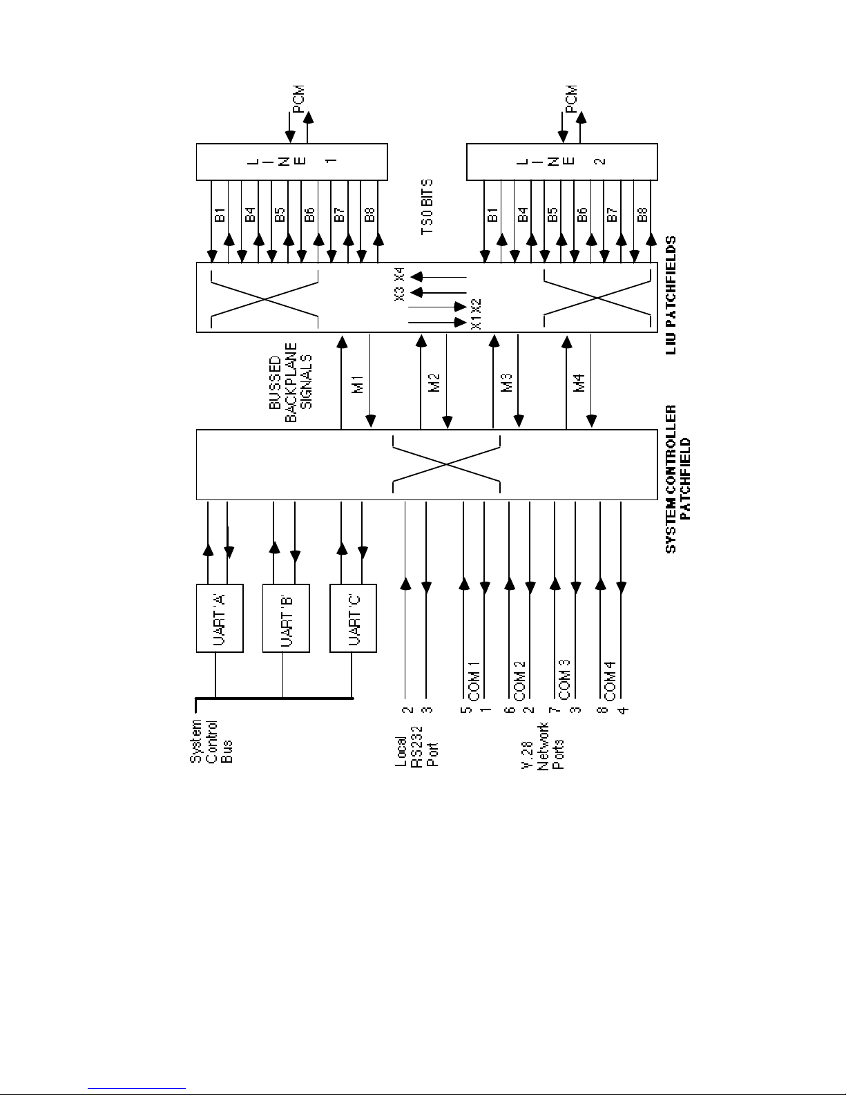
X723-300151 4-7 Issue 2
Figure 4-1 Management Patching Block Diagram
Page 64

X723-300151 4-8 Issue 2
1 2 3 4 5 6 7
PATCH NUMBER
DESTINATION
UARTC UARTC UARTC UARTC UARTC UARTC UARTC
RS232
COMi1 M1COMi1
M1
COMi3 M3COMi3
M3
COMi3
M1
UARTA
M1
UARTA
COMi1
M3
UARTB
M3
UARTB
COMi1
UARTA
COMi1
UARTA COMi2 COMi2
COMi3
UARTB
COMi3
UARTB
UARTC
RS232
UARTA
UARTB
COMo1
COMo2
COMo3
COMo4
M1
M2
M3
M4
COMi4 COMi4
RS232
COMi4
RS232
COMi4
RS232
COMi4
RS232
COMi4
RS232 RS232
M1
M3
COMi1
COMi2
M1
COMi1
COMi2
M3
M3
COMi1
COMi2
COMi3
COMi4
COMi2
COMi3
M1
UARTA
COMi1
COMi2
COMi3
M1
M3
COMi1 COMi1
COMi1
COMi2
COMi2
COMi2
COMi4
COMi4
COMi3
COMi3
M1
M1
M3
M3
UARTA
UARTB
UARTA
UARTB
UARTA
UARTB
COMi3
COMi3
COMi1 COMi1
COMi1 COMi1
COMi2
UARTC UARTC UARTC UARTC M3 M1
UARTB
M3
UARTA
UARTA
UARTA
UARTB
UARTB
Table 4-1 System Controller Patchfield DT990C
Notes:
1. A space in the table above indicates a fixed '1' condition.
2. Where more than one source is shown these are logically 'ANDed' to
the destination.
3. UARTA and UARTB are management serial ports.
4. UARTC is the local serial port.
5. RS232 is the local port connector.
6. M1, M2, M3 and M4 are bits on the management 'M' busses.
7. COMiX and COMoX are V.28 input and output management
connections at the Network Port Connector.
Page 65
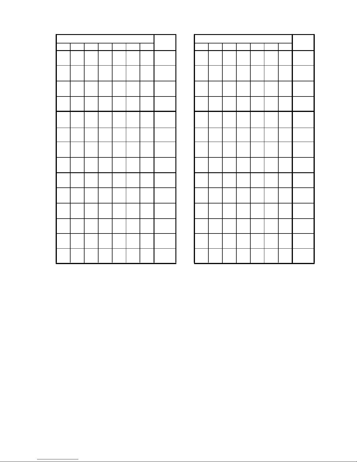
X723-300151 4-9 Issue 2
1 2 3 4 5 6 7
DEST
B4
M1
M2
M1 M2M1 M2M1 M2X1
B5 B7 B7 B6 X2
B5
X3
X4
M1
M2
M3
M4
B1
B4B5
B6
B4 X4B5 X4B4
X4
B4
B7
B8
M1
X3
M2
M1
M2
X4
M1
M2
M1
M2
1 2 3 4 5 6 7
DEST
M3
M4
B6
M3 M4M3 M4M3
M4
X1
B7 B5 B5 B4
X2
B5
X3
X4
M1
M2
M3
M4
B1
B6B7
B6
B6 X2B7
X2
B4
B7
B8
M3
M4
X1
LINE 2 - PATCHLINE 1 - PATCH
X2
X4
X3
X3
X3
X1
X2
M3
M4
X1
M3
M4
M3
M4
M3
M4
B6
X2
X1
M1
M2
Table 4-2 Dual LIU Patchfield DT995D
Notes:
1. A space in the table above indicates a fixed '1' condition
2. Where more than one source is shown these are logically 'ANDed' to
the destination.
3. X1, X2, X3 and X4 are Dual LIU patchfield cross-connect bits.
4. M1, M2, M3 and M4 are bits on the management 'M' busses.
5. B1, B4, B5, B6, B7 and B8 are spare bits in the TS0 Non Frame Word.
Page 66
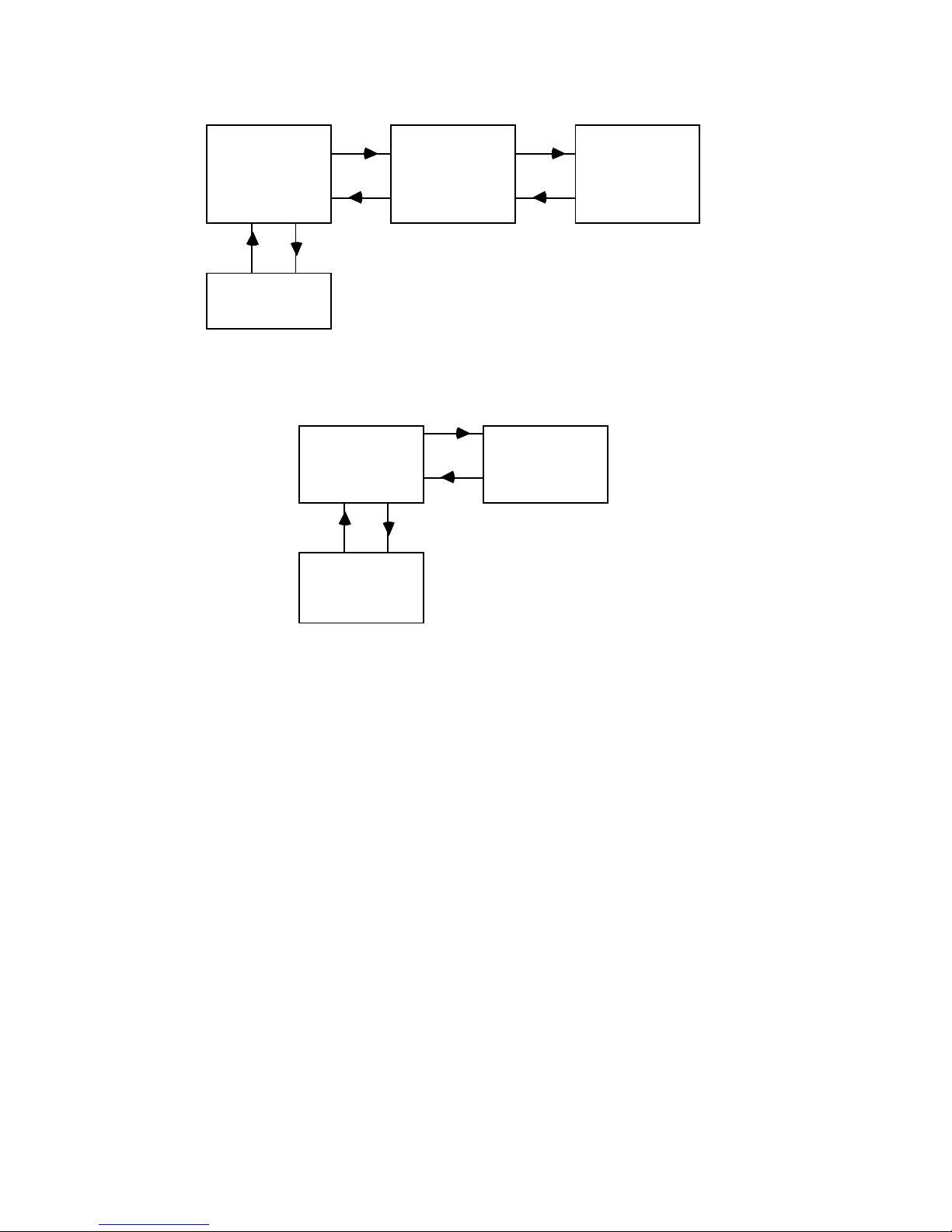
X723-300151 4-10 Issue 2
Source
Polling
Receive
Polling and
Transmit on
Receive
Polling and
Terminate
Mux 1 Mux 2 Mux 3
N.C.S.
V.28
PCM PCM
Figure 4-2 Network Management Patchfield Example
Dumb
Terminal
Local
Mux
Remote
Mux
PCM
Figure 4-3 Local/Remote Patchfield Example
Page 67

X723-300151 5-1 Issue 2
5 Multiplexer Configuration
5.1 Menu Tree
5.1.1 Menu Operation
Menu selections are accomplished by entering the capital/uppercase letter
displayed for the required option and pressing return. The display will
pass to the next associated sub menu or prompt for operator input. See
Section 2.1 for a full description of control terminal operation.
The following sections provide information on the operation of the various
menu commands. Note that the characters in brackets to the left of the
menu, except at root level, indicate the command characters entered to
reach the current point from the root menu. Where data input is required
this may be entered in binary, decimal or hexadecimal with each entry
having a B, D or H suffix as appropriate. If no suffix is appended 'Decimal'
will be assumed.
The 'Maintenance' and 'Fault' sub menus are fully described in Chapter 6.
Menu structures for cards other than Dual LIU cards fitted in ports 1 and
2 may be found in the relevant reference manual for the card.
Root Menu
When the multiplexer is operated in secure mode, the root menu may be in
one of two states:
a) Open
b) Closed
Closed Mode
The operator can only select the 'Open' option at this point and a prompt
for a password will then be obtained.
() Open >O
password >
The password will be entered with the echo suppressed so that the
operators terminal does not show the password. Once the correct
password is entered the standard root menu will be obtained.
Page 68
X723-300151 5-2 Issue 2
If an incorrect password is entered then the menu will revert to the closed
mode. There is no limit to the number of attempts to gain access.
() Maint | Fault | mOde | Configure | Time | Remote | Smart | closE >
Open mode
If the multiplexer is operated in none secured mode (security off) a
password is not required and the root menu will remain open. The display
is the same with the addition of the node ID code at the left.
(P63) Maint | Fault | mOde | Configure | Time | Remote | Smart | closE >
5.1.2 Root Menu
pen O M aint
F ault
m deO
C onfigure
T ime
S mart
R emote
clos E
5.1.3 Time Menu
T
ime
D
isplay
S
et
E
vents
T
ime
D
ate
T
ime
D
ate
L
ist
I
nsert
R
emove
E
nable
D
isable
S
tatus
5.1.4 Mode Menu
m de
O
V
erbose
Brief
choE
Noecho
T
erminal
Tty
urrent
C
y-50
W
nsi
A
I
nstall
et passwordS
assword default
P
isplay passwordD
Ctrl W
Page 69
X723-300151 5-3 Issue 2
5.1.5 Configuration Menu
Same as P1 if a Dual LIU card is fitted *
line1
line2
G.703 Clk o/p
p1
p2
p3
p4
sYnc
Fcode
Bypass
Mode
Error
cR c4
Alarm
Ts assign
Cross connect
Alarm Event
Fcode table
Channel assign
Multipoint
Broadcast
Port
Fcode table
channel assign
Assigned cct
Circuit ctl
Smart configs
Simplex
Duplex
Fixedata assign
Multipoint
line1
line2
line1
line2
line1
line2
Multipoint
Duplex
ext1
ext2
ext3
ext4
Alarm event
Route alarms
Extern relays
Card out
sYnc
Alarms
Origin
Display
Port
Channels
Load
Save
Modify
Current
Run
Edit
List
Install
install A II
Remove
iDent
Channels - see details below
Management
Link
Status
Equipment map
Current
Run
Configure
Enable
Disable
Cross connect
Enable
Disable
Status
Assigned cct
Circuit ctl
Smart configs
p 1
p 2
p 3
p 4
G.703 Clk o/p
line1
line2
sYnc
Fcode
Bypass
Mode
Error
cRc4
Alarm
Ts assign
line1
line2
line1
line2
line1
line2
line1
line2
*
Alarm Event
Route alarms
Extern relays
Card out
sYnc
Alarms
Only when G.703 DLIU
(DTE 241) is fitted
.
Page 70

X723-300151 5-4 Issue 2
5.2 Time Menu
The multiplexer supports a real time clock. The time menu options
provide date entry in the form: day of month, month, year. Using this
together with the time data (day, hour, minute) the multiplexer is able to
calculate the current week number and provide support for weekly timed
event control. The number ranges are 1 to 52 for the week of the year, day
1 to 7 for the week day (Sunday normally = day 1), and standard 24 hour
clock for hour, minute and second. The seconds are not required to be
entered, they will be set to zero when <enter> is pressed.
5.2.1 Time and Date Setting
(T) Display | Set | Events >S
(TS) Time | Date >T
day of week, hour, minute > 4,12,8
(TS) Time | Date >D
day of month, month, year >11,5,94
5.2.2 Time and Date Display
(T) Display | Set | Events >D
(TD) Time | Date >T
current time is week 19, Wk.day 4, hour 12, minute 8, second 43
(TD) Time | Date >D
current date is day 11, month 5, year 94
5.2.3 Timed Events
This uses a single store for all timed events which are accessed on a week
number basis. Displaying, inserting and removing events all require a
week number to be specified. Week numbers range from 1 to 52 with
week 0 as a special selection. Week 0 events will occur in all weeks unless
specifically overwritten. If a specified week event has the same time as a
week 0 event, then the specified week event has priority. When week 0
events are overwritten by editing a selected week (other than 0) they still
operate in all other weeks in which they have not been modified.
The event timer will always run the last valid event prior to the current
time, therefore it is necessary initially to insert an event which will run
the current configuration at a time prior to the current time, for example
five minutes before. This event 1 will be run immediately the events are
enabled and will therefore cause no disruption to traffic.
Page 71

X723-300151 5-5 Issue 2
To set up further timed events, the operator first inserts all of the regular
weekly events giving 0 as the week designator.
To modify a selected week the operator inserts events specifying the
selected week number and normal event data. The inserted event will
then only occur within the given week number and run until the next
week 0 event or another event for that week.
Note: Timed events are intended for multiplexer configuration control in
a stand-alone environment. If the multiplexer is connected to an NCS
then timed events will automatically be disabled, and the network
controller must then be configured if real time events are required.
Creating Timed Events
(T) Display | Set | Events >E
(TE) List | Insert | Remove | Enable | Disable | Status >I
week 1-52 (0=all) >0
day, hour, minute, config >1,12,30,1
day, hour, minute, config >2,12,30,2
day, hour, minute, config >3,12,30,3
day, hour, minute, config >
(TE) List | Insert | Remove | Enable | Disable | Status *>I
week 1-52 (0=all) >20
day,hour, minute, config >2,12,30,4
day,hour, minute, config >3,10,30,5
Displaying Timed Events
(T) Display | Set | Events >E
(TE) List | Insert | Remove | Enable | Disable | Status >L
event 1, - week 0, wk.day 1, hour 12, minute 30, configuration 1
event 2, - week 0, wk.day 2, hour 12, minute 30, configuration 2
event 3, - week 0, wk.day 3, hour 12, minute 30, configuration 3
event 4, - week 20, wk.day 2, hour 12, minute 30, configuration 4
event 5, - week 20, wk.day 3, hour 10, minute 30, configuration 5
Page 72

X723-300151 5-6 Issue 2
Removing Timed Events
The operator may delete events by using the 'Remove' menu option and
specifying the event number. The specified event will be deleted and all
following events re-numbered. A consecutive range of events may be
removed by specifying the start and end event.
(T) Display | Set | Events >E
(TE) List | Insert | Remove | Enable | Disable | Status >R
start event, end event >4,7
Enabling Timed Events
Once the timed events have been created they may be enabled using the
'Enable' menu option. The table will then be compared to the current real
time value and the correct configuration automatically run.
(TE) List | Insert | Remove | Enable | Disable | Status >E
(TE) List | Insert | Remove | Enable | Disable | Status *>
Disabling Timed Events
In order to gain manual or network control of the multiplexer
configuration selection, the timed events may be inhibited using the
'Disable' menu option. It is not possible to run a different configuration to
that called for by a timed event unless the events are first disabled.
(TE) List | Insert | Remove | Enable | Disable | Status >D
(TE) List | Insert | Remove | Enable | Disable | Status *>
Determining Current Status
The current status of the timed events can be checked using the 'Status'
menu option.
(TE) List | Insert | Remove | Enable | Disable | Status *>S
(0) timed events disabled or
(1) no current events or
timed events enabled, configuration 4 requested.
This indicates that the events are enabled and config 4 should be running.
Page 73

X723-300151 5-7 Issue 2
5.3 System Mode Menu
5.3.1 Brief and Verbose Mode Selection
The power up state for these options are defined in the 'mOde' 'Install'
menu, but can be overridden with this command. Brief mode is intended
for test purposes or by an experienced programmer wishing to use a
computer to download a configuration through the local port for example.
The unit must be in verbose mode to operate with the NCS.
(O) Verbose | Brief | Echo | Noecho | Terminal | Install >B
*>
>
>V
(O) Verbose | Brief | Echo | Noecho | Terminal | Install *>
Note that in the above example when 'Brief' is selected the menu options
are suppressed with the '>' character indicating that a command input is
required.
5.3.2 Echo and Noecho Selection
The power up state for these options are defined in the 'mOde' 'Install'
menu, but can be overridden with this command.
(O) Verbose | Brief | Echo | Noecho | Terminal | Install >N
This will inhibit the operator input from being returned to the operator
terminal and will remove the CR/LF controls.
(O) Verbose | Brief | Echo | Noecho | Terminal | Install >E
This will restore the echo mode again.
5.3.3 Control Terminal Configuration
The multiplexer provides a menu for the purpose of setting the terminal
type connected by the operator. This modifies the screen control
characters issued by the multiplexer for screen display, e.g. the characters
sent during a backspace.
(OT) Tty | Ansi | Wy-50 | Current >C
operator terminal = ANSI
Page 74

X723-300151 5-8 Issue 2
5.3.4 Install Menu. E2PROM Programming
The operator may select a range of modes of operation using the 'Install'
menu option. This will show the current setting and present each
configurable mode option and allow the operator to change the setting. If
no change is required then pressing the Return/Enter key will skip to the
next item.
(O) Verbose | Brief | Echo | Noecho | Terminal | Install >I
Network letter is P (A - Z excluding N) >
Network number is 63 (1 - 63) >
Control port is local (0=local 1=a 2=b) >
Security is off (0=off 1=on) >
Start-up with echo (0=noecho 1=echo) >
Start-up in verbose (0=brief 1=verbose) >
Start-up fault logging is logging (0=off 1=logging 2=asr) >0
Redundant disabled (0=disabled 1=enabled) >
Expansion disabled (0=disabled 1=enabled) >
Alarm event detect period is 5 (0-60) >
Alarm event hold period is 5 (0-60) >
Alarm event channel card fault level is 16 (1-16) >
Network port A enabled (0=disable 1=enable) >
Network port B enabled (0=disable 1=enable) >
Network enabled (0=disable 1=enable) >
Network CRC Upload enabled (0=disable, 1=enable) >
Network CRC Upload Timer Offset 300 (180 to 720) >
Network C/D Upload enabled (0=disable, 1=enable) >
Network C/D Auto Clear enabled (0=disable, 1=enable) >
PSU A absent (0=absent 1=fitted) >
PSU B absent (0=absent 1=fitted) >
-48v absent (0=absent 1=fitted) >
Manage Port A baud rate is 1200 (600,1200,2400,9600) >
Manage Port B baud rate is 1200 (600,1200,2400,9600) >
Manag Config 1 5 10 14 D
System management 1, 1, 1, 1, 1, 1, 1, 1, 1, 1, 1, 1, 1, 1, 1 >
LIU 1 management1 1, 1, 1, 1, 1, 1, 1, 1, 1, 1, 1, 1, 1, 1, 1 >
LIU 1 management2 1, 1, 1, 1, 1, 1, 1, 1, 1, 1, 1, 1, 1, 1, 1 >
LIU 2 management1 1, 1, 1, 1, 1, 1, 1, 1, 1, 1, 1, 1, 1, 1, 1 >
LIU 2 management2 1, 1, 1, 1, 1, 1, 1, 1, 1, 1, 1, 1, 1, 1, 1 >
Severely errored second limit 805 (1-915) >
In the example above one parameter was changed. At the end of the
options list the operator is then prompted to check if changes are to be
permanently installed.
changes have been made, do you wish to install (Yes No) >Y
Saving installed modes . . . . completed ok!
Page 75

X723-300151 5-9 Issue 2
(O) Verbose | Brief | Echo | Noecho | Terminal | Install *>
The modes of operation are stored in an E
2
PROM and the saving action
can take up to one minute to complete. The E
2
PROM does not require
battery back up and the information will be retained during power off
conditions even if the battery is disconnected. When the multiplexer is
being remotely controlled via an NCS and the install options are saved,
the operator must wait for the 'completed OK' message to be displayed
and then enter Ctrl + X to exit Remote control. If remote access is still
required the multiplexer must be re-accessed.
Equipment Identity Code
The option to set a discreet identity code for each multiplexer is provided,
except for N any letter from A to Z plus any number from 1 to 63 may be
selected, e.g. P10. It is important that Z is not be used if the node is in a
network under the control of the NCS version 3.1 or above as Z is used for
zone identity. This will be the number displayed at root menu level (non
secure mode) and also to identify faults. When under the control of the
NCS, this ID code will be used by NCS to address that node, and therefore
must not be duplicated on any other equipment in the network. If the
equipment number is changed and the default password is in use, the
password must be reset.
Control Port Selection
This option is used when the multiplexer is used in Local/Remote mode.
The local multiplexer should be set to local and the remote multiplexer
should be set to either 'a' or 'b' depending upon the selected management
patchfield. When the unit is network managed it should be set to local.
Secure Mode Selection
The operator may use the multiplexer in secure mode, this enables the
menu system to be 'closed' and a password will then be required at the
local control port to gain access to the menu structure. The network ports
'a' and 'b' are not password protected.
Screen Display Modes
The start up (switch on) screen display may be set to echo/noecho or
brief/verbose.
Fault Logging
The start up state of the fault reporting may be selected to Off, Logging or
ASR. These reporting modes are described in Chapter 6.
Page 76

X723-300151 5-10 Issue 2
Redundant Mode Operation
This facility must be enabled if a redundant system controller is fitted.
Expansion Mode Operation
This facility is not available in these multiplexers and must be set to
disabled.
Alarm Event Detect Period
If a system configuration is programmed for an alarm event, then the
alarm fault must exist for the specified period prior to the event occurring.
The selection of a new system configuration will reset the detect period
which must then be completed prior to a second event occurring. The
detect period is the time in seconds. Note if 0 is set the detection period
will be between 0 and <1 second.
Alarm Event Hold Period
The alarm event hold period determines the amount of time a new system
configuration will be active prior to further alarm events being allowed to
occur. The time is in seconds.
Alarm Event Channel Card Fault Level
The alarm level set will be used to determine the failure of any circuit
specified as an alarm event source. The fault level is the NCS fault level
which may be determined from the fault tables in Chapter 6.
Network Operation
The multiplexer may be operated on a network using the Network Control
System (NCS), and this facility may be enabled or disabled. For
local/remote working, network operation must be disabled.
CRC4, Counts and Durations Statistics gathering
The 3000 Series, build 6 or later, node supports enhancements to Network
Management communications protocols to allow the efficient collection of
CRC4, Counts and Durations statistics information from any node by the
Network Control System. The Network CRC and Counts and Durations
(C/D) install options allow these enhancements to be selectively turned on
and off, and CRC4 upload delay to be adjusted.
Page 77

X723-300151 5-11 Issue 2
Note that the following two items relate to a DomainView feature for
collecting statistics, and do not affect the general operation of the
multiplexer. For normal operation with NCS, these features must be
disabled.
1 Network CRC Upload enabled (0=disable, 1=enable) >
Network CRC Upload Timer Offset 300 (180 to 720) >
This enables and disables the CRC4 upload function in the node.
When enabled, at the end of every 15 minutes (on the hour, quarter
past the hour etc) CRC4 analysis cycle, the node will signal to NCS
that it has the CRC statistics for all the Dual LIUs fitted in the node.
This will trigger the NCS to immediately request the data. In larger
networks, it is advisable to stagger these ‘uploads’ to prevent networks
being clogged with the CRC4 upload data from all the nodes. The
Upload Timer Offset sets the delay in seconds from the 15 minute
boundary to when the node signals it has CRC data available. In this
way, it is possible to arrange that all the nodes do not signal
simultaneously CRC data available.
2 Network C/D Upload enabled (0=disable, 1=enable) >
Network C/D Auto Clear enabled (0=disable, 1=enable) >
This enables and disables the C/D upload function in the node. This is
normally a once per day event controlled by the NCS. When enabled,
on receipt of the C/D command from NCS, it uploads all the Counts
and Durations information from all the Dual LIUs fitted. When
disabled, this command is ignored. If the auto clear is enabled, the
Dual LIU automatically clears down all counts and durations after
they have been read by NCS.
Power Monitoring
The power units in the 3000 power supply equipment can be monitored to
indicate a fault on failure, this will occur if 'fitted' is selected. The
operator should select 'fitted' when 2 power supplies are intended to be
fitted in the chassis.
The -48VDC required for some channel interface cards and ringing
generators is also monitored; if this is not used it should be set to 'absent'.
Management Configuration
The Baud rate for network management must be specified for each port,
normally this is 1200, but must be set to the same baud rate as the NCS.
Page 78

X723-300151 5-12 Issue 2
It should be noted that 9600 is only for local Test access to the Network
Management UARTs on the System Controller and must not be used
across the network.
Each management configuration (1-14+Default) specifies one of the seven
patchfields available on the System Control cards and Dual LIU cards
fitted in ports 1 and 2. Note that the patchfields for any Dual LIUs fitted
in ports 3 and 4 are set by hardware switches. The display gives a
configuration number index across the top and by reading the relevant
column the patch selections can be determined. In order to modify the
management the entire set of 15 numbers must be entered at the relevant
line. The 'D' column specifies the patchfields selected for the default
configuration which will be run if the unit becomes un-configured due to
the backup battery becoming discharged.
Severely Errored second Limit
This sets the number of errors in any one second before it is classed as a
severely errored second. If it is set to 915, the counter will be disabled.
5.3.5 Security Password Modification
This command allows the operator to set the password utilised when in
secure mode. Note that this is a hidden menu option and requires the
operator to enter Ctrl + W - ENTER to access it.
The password is in the form of up to 8 alphanumeric characters.
(O) Verbose | Brief | Echo | Noecho | Terminal | Install >^W
(O) Set password | Display password | Password default *>S
new password > SUNSHINE
Selecting 'Password Default' will set the password to the default which is
ENETXX where XX is the equipment identity number. Note that if the
equipment number is changed in the 'Install' menu, then 'Password
default' must be re-selected otherwise the previous number will remain as
part of the default password.
Page 79

X723-300151 5-13 Issue 2
5.4 Configuration Menu
5.4.1 Checking and Running Channel Configurations
The operator must select 'Configure' 'Channel' (CC) from the root menu
and may then display which is the 'Current' configuration, 'Run' a new
configuration or enable/disable the 'Alarm events' for
ALL configurations
using the following menu commands.
(CC) Current | Run | Edit | Alarm event >
5.4.2 Editing and Displaying Channel Configurations
Commands are provided to allow the operator to 'Load' either a previously
edited configuration field or the default into an edit buffer. The edit buffer
is where all changes are made by using the 'Modify' command, and is the
‘configuration’ viewed by the ‘Display’ command. After editing, another
menu selection is provided for 'Saving' the buffer into a system
configuration. If the save is into a configuration field that is already
running, then the operator will be prompted to continue or abort. If
continuing, the configuration is saved and run immediately.
(CC) Current | Run | Edit | Alarm event >E
(CCE) Load | Save | Modify | Origin | Display >L
configuration no | Default >2
(CCE) Load | Save | Modify | Origin | Display >S
configuration no | Default >1
Warning configuration is current - continue Yes | No >
After loading the desired configuration in to the edit buffer, the operator
may select the 'Modify' or 'Display' command in order to modify or display
its contents. In order to check where the last edit buffer load was made
from, the 'Origin' option is provided.
Timeslot allocation and routing through the multiplexer is carried out in
two separate stages:
i) Timeslots from the Port in which the card is inserted have to be
assigned to the relevant circuit on the card, using the 'Assigned
cct' command.
ii) These timeslots may be routed through the switch to any
destination using the 'Cross Connect' menu option. (Refer to
Figure 1-1).
Page 80

X723-300151 5-14 Issue 2
The following descriptions of configuration options show the 'Modify' and
'Display' formats for each option.
Port Integrated Menu Support
The 3000 Series provides integrated menu support for some channel cards,
e.g. Dual Nx64 LIU and Dual G.703 DLIU. Refer to the channel card
manuals for the menus provided for all cards except Dual G.703 LIU
which is covered in this manual.
Integrated menu support can be accessed via Modify Port p1 option for a
card fitted in port 1, Modify Port p2 for card fitted in port 2. On selection
of Modify Port p3 and p4 options, the user is given the option to select the
card slot A, B... for each physical port.
If the card fitted in that slot has integrated support, the appropriate
menus will be displayed seemlessly. If the card fitted is not supported in
that slot, the ‘Not available on card fitted or card missing’ message will be
issued.
5.4.3 DLIU Integrated Menu
A Dual G.703 LIU fitted in port 1 and 2 is configured using the following
menu structure. Dual LIU cards fitted in ports 3 and 4 are configured
using the 'Smart' menu option as described in the Dual LIU manual.
Modify Format
This command allows the user to set the operating parameters for ports 1
and 2 when fitted with a Dual LIU card DTE241.
(CCEM) Port | sYnc | Alarms | Cross connect >P
(CCEMP) Assigned cct | Circuit ctl | Smart configs | p1 | p2 | p3 | p4 >1
(CCEMP1) sYnc | F code | Bypass | Mode | Error | cRc4 | Alarm | Ts assign >
1) Sync
This will allow the operator to set the parameter for detecting the loss
of the incoming signal when it is used as a synchronising source. This can
be either:-
1 Line Loss
2 Line Loss or Service Loss
3 Line Loss, Service Loss or receipt of a Remote Alarm. (Bit 3 in TS0)
4 Line Loss or receipt of a Remote Alarm
Service Loss is defined as: loss of Frame sync, AIS or a 10
-3
error rate.
Page 81

X723-300151 5-15 Issue 2
These parameters may be set individually for line 1 or line 2.
The user may also select the state (enabled or disabled) of the G.703 clock
output when the multiplexer is free running via G.703 Clk o/p menu.
2) F code
This will allow the on-going data in each timeslot and associated
signalling to be determined should the source data fail. The data may be
set individually for line 1 and line 2. Note: ''F' Codes are overwritten with
FFH when the respective timeslot is a multipoint timeslot.
3) Bypass
The bypass condition for the lines, i.e. connecting line 1 to line 2, or for the
clock, i.e. connecting clock I/P to clock O/P may be set. If set to enabled,
the Line or Clock circuits will be permanently bypassed for that
configuration. The normal setting is disabled which will allow the circuits
to automatically switch to 'Bypass' should the card fail, be removed or
during power failure.
4) Mode
Three modes of operation may be set. If firmware DT986/6 is fitted to the
Dual LIU, additional options are provided for each mode to set the routing
for the TS0 'Not Frame alignment Word' (NFW) There are 8 options
which are fully described in section 3.1.1.
1 Multipoint.
This will connect all timeslots and signalling through from line 1 to line 2,
and provide the facility to multipoint additional timeslots from the
multiplexer switch, or to drop and insert individual timeslots from either
line to the multiplexer switch. Line 1 and line 2 must be in the same
signalling mode, i.e. CAS or CCS. Fault logging may also be individually
enabled or disabled for line 1 or line 2.
If fault logging is disabled, faults will not be reported from that line signal
and may be used if a line is to be taken out of service. If multiframe
linking is selected, the delay between multiframes received on line 1 and
transmitted on line 2 will be minimised. Similarly, the delay between
multiframes received on line 2 and transmitted on line 1 will be
minimised.
Note: When multiframe linking is enabled, incoming frame slips will
cause multiframe re-alignment and Frame Sync loss may occur
Page 82

X723-300151 5-16 Issue 2
momentarily on the host equipment and also on equipment connected to
the host.
2 Terminal.
This will isolate line 1 from line 2 providing two separate PCM paths to
the cross connect switch. Signalling may be different on line 1 and line 2
(CAS or CCS) and fault logging may be individually set as for multipoint.
In terminal mode, the mapping of PCM timeslots to the backplane
streams is fixed. The selection of ‘TS Assign’ menu is inhibited, and user
will be warned that this option is ‘Not available in this mode’.
In port 1, line 1 is connected to backplane stream s1, line 2 to s2. In port
2, line 1 is connected to backplane stream s3, line 2 to s4. In all cases
PCM timeslots 1, 2, 3,....31 are connected to backplane stream timeslots 1,
2, 3,....31.
3 A/B Switching.
This mode is designed to change from one line to another upon a specific
line failure. All timeslots for both outgoing line streams will be sourced
from the relevant stream (S1 for port 1 or S3 for port 2) and all timeslots
from the active line signal will be connected to the relevant stream as
indicated below. The mapping of PCM timeslots to the backplane streams
is fixed with TS1, 2, 3,....31 of the backplane stream. The selection of ‘TS
Assign’ menu is inhibited, and user will be warned that this option is ‘Not
available in this mode’.
The operator can set the following options:
i) Signalling mode
This must be the same for both PCM streams; either CAS or CCS.
ii) Switch over delay (Fault Persistency)
This delay parameter will be used to inhibit change-over of the
PCM source until the PCM fault has been present for the delay
period.
iii) Hold delay
This parameter will be used to disable operation of the switch over
facility immediately after a change-over. The facility will be reenabled after the delay period has expired.
Note: Both the switch over delay timer and the hold delay timers
run in parallel and not consecutively therefore the hold delay must
Page 83

X723-300151 5-17 Issue 2
be set greater than the change over delay by the amount of hold
period that is required.
Time delays are selectable between 0 and 25 seconds in steps of
100ms.
iv) Dual management path
When this facility is enabled, management data will operate as in
terminal mode e.g.
i) TS0 data from line 1 will be written to line 1 patchfield.
ii) TS0 data from line 2 will be written to line 2 patchfield.
iii) Data read from line 1 patchfield will be written to line 1 TS0.
iv) Data read from line 2 patchfield will be written to line 2 TS0.
When disabled, this facility will operate as follows:
i) Data read from the active line signal will be written to the
relevant active portion of the patchfield.
ii) Data written to the inactive portion of the patchfield will be all
1's.
iii) Data read from line 1 patchfield will be written to line 1 TS0.
iv) Data read from line 2 patchfield will be written to line 2 TS0.
v) A/B sync source tracking
This facility can be enabled or disabled.
When enabled, the sync source used from this LIU will
automatically be derived from the active line. This clock should
be selected in the multiplexer sync plan as Line 1 clock. Line 2
clock is not used.
When disabled, Line 1 and Line 2 clocks may be used as sync
sources in the multiplexer sync plan in the normal way.
Failure Conditions
The following faults are used to determine a line failure condition.
AIS
Loss of Incoming PCM
Loss of Frame alignment
Error ratio > 1 in 10
-3
TS16 AIS if set for CAS mode
Loss of Multiframe alignment if set for CAS mode
Low error rate
CRC reframe when CRC is enabled.
Page 84
X723-300151 5-18 Issue 2
Change-over Operation
The decision to switch or not to switch will be made on the basis of the
table below when the delay time expires. Faults which occur and clear
within the switch over delay time will not be considered for the purposes
of the decision table.
ACTIVE STREAM STANDBY STREAM
ACTION
No fault No fault
None
Low error rate No fault
Switch
Low error rate Any fault
None
Any fault except low
error rate
Low error rate
Switch
Any fault except low
error rate
Any fault except low
error rate
None
Faults
During failure conditions, PCM alarm responses will be set and reported
as for normal PCM operation of the LIU. If PCM Line 1 is selected, the
following status message will be generated in the active fault list:-
'Path A selected'.
Similarly if PCM Line 2 is selected, the following status message will be
generated:-
'Path B selected'.
These 'faults' are used as information markers, and have a network fault
level of zero and cause no alarm relay or LED operation.
Fault Persistency
One fault may cause the change over timer to start running, but that
same fault need not be active when change-over occurs, another fault may
take its place, e.g. PCM loss occurs and is then replaced by AIS. Only
when all relevant faults have been cleared will the timer be reset.
5) Error
The threshold for the low error rate detector may be individually set to
10
-4
, 10-5 or 10-6 for line 1 and line 2. This does not affect detection of 10
-3
which is required for line service monitoring. If the threshold is exceeded,
then the low error rate fault is generated.
Page 85

X723-300151 5-19 Issue 2
6) CRC4
The CRC4 error checking facility may be individually enabled or disabled
for line 1 and line 2. If CRC4 is enabled, the user has the option to
enable/disable the low error rate detection using CRC4. If enabled, the
low error rate is calculated using CRC4. If disabled, the low error rate is
calculated using the timeslot zero frame word. Note that CRC4 must be
enabled at
BOTH ends of the PCM stream otherwise data loss, including
loss of the management path, will occur due to CRC Reframe causing loss
of Frame sync.
7) Alarm
This allows the user to define the conditions for detecting the loss of
incoming signal when it is used to trigger an alarm event. The
parameters can be individually set for line 1 and line 2 and are the same
as those for sync (5.4.3 1)).
8) Ts Assign
DUPLEX
This method of timeslot assignment should be used where the Dual LIU is
required to operate in Multipoint (Drop/Insert) mode. Selecting 'Duplex'
allows individual timeslots to be dropped/inserted to either Line 1 or Line
2 timeslots from the matching timeslots on the cross-connect switch. In
port 1: line 1 is connected to S1; line 2 to S2. In port 2: line 1 is connected
to S3; line2 to S4. To make the connection, select the line required, 1 or 2,
and then enter 'E' for the timeslot it is required to Drop/Insert. In the
following example timeslots 1 and 2 will be dropped /inserted from P1 Line
1 to timeslots 1 and 2 of S1. Timeslots 1 and 2 in Line 2 will be replaced
by the Fcode since they are no longer connected through to Line 1.
Alternatively they may be reused and dropped/inserted to S2.
(CCEM1T) Multipoint | Duplex >D
(CCEM1TD) Line 1 | Line 2 >1
first timeslot, last timeslot >1
(TS1, ) *>E
(TS2, ) *>E
(TS3, ) *>
(TS4, Duplex ) *>
Page 86

X723-300151 5-20 Issue 2
Up to 31 timeslots may be selected and timeslots which are already
connected will be shown as 'Duplex'. To disconnect an allocated timeslot
enter U.
MULTIPOINT
Selecting multipoint operation is exactly the same as ‘Duplex’ except that
the timeslots are also allowed to pass through from Line 1 to Line 2 in
duplex as well as being dropped/inserted to the relevant stream on the
cross connect switch. The timeslot fromthe switch is multipointed
(logically ‘ANDed’) with the through timeslot from the other line. The
display will show ‘Multipoint’ instead of ‘Duplex’.
Display Format
This command allows the display of all of the parameters set above.
(CCED) Port | sYnc | Alarms | Cross connect >P
(CCEDP) Assigned cct | Circuit ctl | Smart configs | p1 | p2 | p3 | p4 >1
(CCEDP1) sYnc | F code | Bypass | Mode | Error | cRc4 | Alarm | Ts assign >
Each parameter may be selected for display only - no changes are possible.
Page 87

X723-300151 5-21 Issue 2
5.4.4 Sync Source
A menu command allows the operator to modify the sync source and sync
priority selections for the configuration of the multiplexer. Up to four sync
source selections can be entered after which the list will be terminated
with free run.
Modify Format
Each sync source selected will be displayed in turn until freerun is
reached. The last sync source in any selection will always be free run.
(CCEM) Port | sYnc | Alarms | Cross connect >Y
failure recovery mode 1 (manual), 2 (automatic)
mode = 2 >
automatic recovery delay period 1-60 (seconds)
hold = 10 >
source selections:
1 (port)
2 (8k1)
3 (8k2)
4 (free run)
priority 1 = 4 (free run) >1
port (1,2,3,4),card,option (1=line1 2=line2 3=clk)>3, C, 2
priority 2 = 4 (free run) >1
port (1,2,3,4),card,option (1=line1 2=line2 3=clk)>2, A, 1
priority 3 = 4 (free run) >
(CCEM) Port | sYnc | Alarms | Cross connect *>
If manual clock recovery is selected, the multiplexer will automatically
fallback to a lower priority clock, but will only re-select a higher priority
clock by manually re-running the current configuration. If automatic
clock recovery is selected the sync source will automatically revert to the
highest good source available. The switch back may be delayed for up to
60 secs from when the good clock is first detected.
The Series 3000 can be synchronised to a 2MHz or two 8kHz, known as
8k1 and 8k2, internal clock busses generated by certain channel cards.
Access to the 2MHz clock bus is fully controlled by the system controller.
However, access to the 8kHz busses are not. This is controlled by link
selection on the channel cards. Care should be taken to ensure only one
channel card is connected to each of the 8kHz clock busses at any one
time.
Page 88

X723-300151 5-22 Issue 2
The ‘port’ selection allows the user to select channel cards which supports
2048 kHz clock bus as the sync source multiplexer. In the example above,
the line 2 of the card fitted in port 3, card slot c has been selected as the
priority 1 clock source. Selection of the clocks is automatic.
8k1, 8k2 options allow the user to select the 8k1, or 8k2 busses as the sync
source.
Display Format
(CCED) Port | sYnc | Alarms | Cross connect >Y
recovery mode (2) automatic
clock priority 1 sourced from port 1, card A, line 2
clock priority 2 sourced from port 2, card A, line 1
clock priority 3 sourced from freerun
(CCED) Port | sYnc | Alarms | Cross connect *>
5.4.5 Alarm Events, Route Alarms and External Control Relays
Each configuration may be set to run another configuration on a specified
fault condition. The condition can be set to be the failure of an incoming
PCM stream or a fault on a channel card which must exist for a period
defined within the 'Mode Install' menu.
Up to eight circuits may be identified as 'Route alarms' for use by the NCS
for re-routing purposes. They have no use in non-networked mode.
Four relays are provided on the 3200 for control of attached equipment.
These relays may be set to operate as required for different configurations.
5.4.5.1 Alarm Events
Modify Format
(CCE) Load | Save | Modify | Origin | Display *>M
(CCEM) Port | sYnc | Alarms | Cross connect >A
(CCEMA) Alarm event | Route alarms | Extern relays | Card out >A
enter start stream, start circuit >S1
config. options 1-14 (U = unassigned)
(S1) alarm config. 1 >
(S2) alarm config. Unassigned >8
(S3) alarm config. 1 >4
(S4) alarm config. Unassigned >
(CCEMA) Alarm event | Route alarms | Extern relays *>
(CCEM) Port | sYnc | Alarms | Cross connect >A
Page 89

X723-300151 5-23 Issue 2
(CCEMA) Alarm event | Route alarms | Extern relays | Card out >A
enter start stream, start circuit >P3, A1
config. options 1-14 (U = unassigned) >
(P3, cct A1) alarm config Unassigned >
(P3, cct A2) alarm config 4 >
(P3, cct A3) alarm config Unassigned >
(P3, cct A4) alarm config Unassigned >5
(CCEMA) Alarm event | Route alarms | Extern relays *> | Card out >A
PCM streams for Dual G.703 LIU cards in port 1 and 2 should be entered
as S1 for Port 1 Line 1, S2 for Port 1 Line 2, S3 for Port 2 Line 1, and S4
for Port 2 Line 2. Other channel cards e.g. Dual Nx64 LIU should be
entered as P1, A1 for Port 1 circuit 1, P1, A2 for Port 1 circuit 2 etc.
Display Format
(CCED) Port | sYnc | Alarms | Cross connect >A
(CCEDA) Alarm event | Route alarms | Extern relays | Card out >A
S2, alarm config 1
S3, alarm config 8
S4, alarm config 4
P3, cct A2 alarm config 4
P3, cct B2 alarm config 5
The display option will list all sources of alarm events that are currently
assigned.
With the alarm event triggers set in the configuration, the operator must
then 'Enable' the alarm events before they will function.
(CC) Current | Run | Edit | Alarm event >A
(CCA) Enable | Disable | Status >E
To disable alarm events so that a change of PCM status does not cause a
configuration change, the 'Disable' menu option should be selected.
(CCA) Enable | Disable | Status >D
In order to check the current alarm event mode, the 'Status' option may be
selected.
(CCA) Enable | Disable | Status >S
alarm events currently disabled.
Page 90

X723-300151 5-24 Issue 2
5.4.5.2 Route Alarms
Modify Format
(CCEMA) Alarm event | Route alarms | Extern relays | Card out >R
(Route 1 ) Stream 1 >
(Route 2 ) Stream 2 >
(Route 3 ) Stream 3 > P4,B2
(Route 4 ) Stream 4 > S3
(Route 5 ) Port 3, Circuit A1 >
(Route 6 ) Port 3, Circuit A2 >S4
(Route 7 ) Port 4, Circuit A1 >
(Route 8 ) Port 4, Circuit A2 > P4,B1
(CCEMA) Alarm event | Route alarms | Extern relays | Card out *>
The default circuits for route alarms 1 to 8 are listed in Sec 5.4.18 (10).
Route alarms can not be unassigned, but do not have to be used by the
NCS. PCM streams for Dual G.703 LIU cards in ports 1 and 2 should be
entered as S1 to S4. Other channel cards, e.g. dual Nx64k cards in ports 1
and 2 should be entered as P1,A1 - P1,A2 - P2,A1 - P2,A2.
Display Format
(CCEDA) Alarm event | Route alarms | Extern relays | Card out >R
(Route 1 ) Stream 1
(Route 2 ) Stream 2
(Route 3 ) Port 4, Circuit B2
(Route 4 ) Stream 3
(Route 5 ) Port 3, Circuit A1
(Route 6 ) Stream 4
(Route 7 ) Port 4, Circuit A1
(Route 8 ) Port 4, Circuit B1
(CCEDA) Alarm event | Route alarms | Extern relays *>
5.4.5.3 External Relays
Modify Format
(CCEMA) Alarm event | Route alarms | Extern relays | Card out >E
(CCEMAE) ext 1 | ext 2 | ext 3 | ext 4 >1
ext 1 Disabled (0=disable 1=enable) >1
(CCEMAE) ext 1 | ext 2 | ext 3 | ext 4 *>
Page 91

X723-300151 5-25 Issue 2
This action will cause external relay number one to be operated when the
configuration is run.
Display Format
(CCEDA) Alarm event | Route alarms | Extern relays | Card out >E
ext 1 relay Enabled
ext 2 relay Disabled
ext 3 relay Disabled
ext 4 relay Disabled
(CCEDA) Alarm event | Route alarms | Extern relays | Card out *>
5.4.5.4 Card Out
This allows the user to configure an alarm event to be triggered by the
removal of a card from Port 1 or Port 2
Modify Format
(CCEMA) Alarm event | Route alarms | Extern relays | Card out >C
enter start port> P1
config options 1-14 (U=unassigned)
(P1 card out) alarm config Unassigned> 1
(P2 card out) alarm config Unassigned> 1
(CCEMA) Alarm event | Route alarms | Extern relays | Card out >C
Display Format
(CCEDA) Alarm event | Route alarms | Extern relays | Card out >C
(P1 card out) alarm config 1
(P2 card out) alarm config 1
(CCEDA) Alarm event | Route alarms | Extern relays | Card out >C
5.4.6 Circuit Assignments
(CCEM) Port | sYnc | Alarms | Cross connect >P
(CCEMP) Assigned cct | Circuit ctl | Smart configs | p1 | p2 | p3 | p4 >
The 'Assigned cct' menu command provides the facility for assigning
circuits to the timeslots associated with each port and for setting the value
of the TS control byte used on VF channel cards. This value need not be
entered if the TS control port is not used, or is unchanged.
Page 92

X723-300151 5-26 Issue 2
Modify Format
(CCEMP) Assigned cct | Circuit ctl | Smart configs | p1 | p2 | p3 | p4 >A
port, first, last timeslot >P4
(P4,TS 1) cct = , TS control = 00000000B >A1, 10001010B
(P4,TS 2) cct = , TS control = 00000000B >A2
The first timeslot to be assigned may be selected to be TS0 to TS31. If no
first timeslot is selected, TS1 will be presented as in the example above.
This menu option also supports a block assignment mode. If values are
entered for the first and last timeslot, then only one circuit i.d. will be
requested. All timeslots in the range will then be allocated to the
designated circuit. Note that this mode should only be used for circuits
supporting multiple timeslots. The timeslots will be consecutively
allocated to the circuit. The TS control byte can not be altered without
first re-entering the circuit identity.
Display Format
(CCEDP) Assigned cct | Circuit ctl | Smart configs | p1 | p2 | p3 | p4 >A
port, first, last timeslot >P4, 10, 12
(P4,TS,10), cct = A1 , TS control = 10001010B
(P4,TS 11), cct = A2 , TS control = 00000000B
(P4,TS 12), cct = A3 , TS control = 00000000B
5.4.7 Circuit Controls
This menu command provides a facility for setting and displaying the two
control ports for the channel cards in any port. If only control port 1 is
used a value for control port 2 need not be entered. Refer to the relevant
channel card manual for control port byte values.
Modify Format
(CCEMP) Assigned cct | Circuit ctl | Smart configs | p1 | p2 | p3 | p4 >C
port, first cct >P3, A1
(P3, cct A1, TS 14), 1 = 11111011B, 2 = 11111111B > FFH
(P3, cct A2, TS 15), 1 = 11111011B, 2 = 11111111B > A5H
(P3, cct A3, TS 17), 1 = 11111011B, 2 = 11111111B > 11011011B
(P3, cct A4, TS 18), 1 = 11111011B, 2 = 11111111B > 11011101B, 10110101B
Display Format
(CCEDP) Assigned cct | Circuit ctl | Smart configs | p1 | p 2 | p 3 | p 4 >C
port, first cct >P4 A1
Page 93

X723-300151 5-27 Issue 2
(P4, cct A1, TS 5),control 1 = 11111111B, control 2 = 11111111B
(P4, cct A2, TS 6),control 1 = 10100111B, control 2 = 11111111B
(P4, cct A3, TS 7),control 1 = 11011011B, control 2 = 11111111B
(P4, cct A4, TS8 ),control 1 = 11011101B, control 2 = 10110101B
5.4.8 Smart Configurations
Each channel configuration must specify an associated configuration
number for each smart channel card installed. When a system channel
configuration is run this information is then used to determine the correct
smart channel card configuration numbers. Smart cards can have up to
four configurations.
Modify Format
(CCEMP) Assigned cct | Circuit ctl | Smart configs | p1 | p2 | p3 | p4 >S
port 1 card A smart config 1 >
port 2 card A smart config 1 >
port 3 card A smart config 4 >3
port 3 card C smart config 2 >
port 4 card E smart config 2 >
Note that only the port card positions actually installed with smart
channel cards are displayed and made available for modification.
If port 1 or Port 2 is fitted with a Dual LIU card DTE241 the config
requested should be ignored; these would be used if the ports were fitted
with, for example, a T1 Line access card.
Display Format
(CCEDP) Assigned cct | Circuit ctl | Smart configs | p1 | p2 | p3 | p4 >S
port 1 card A smart config 1
port 2 card A smart config 1
port 3 card A smart config 3
port 3 card C smart config 2
port 4 card E smart config 2
5.4.9 Fixed Code Table
A Menu command allows the user to modify the fixed code table. There
are 16 codes available and these may be changed to suit operator
requirements for timeslot data and associated signalling data. When
configuring 'Fixedata' it is only necessary to select the code number.
Page 94

X723-300151 5-28 Issue 2
Modify Format
(CCEMC) Fcode table | Channel assign >F
Fcode no (1 to 16) >1
1 data, signal = FFH; FH >
2 data, signal = FFH; FH >AAH,AH
3 data, signal = FFH; FH >55H,5H
4 data, signal = FFH; FH >01H,FH
5 data, signal = FFH; FH >
6 data, signal = FFH; FH >
7 data, signal = FFH; FH >
8 data, signal = FFH; FH >
9 data, signal = FFH; FH >
10 data, signal = FFH; FH >
11 data, signal = FFH; FH >
12 data, signal = FFH; FH >
13 data, signal = FFH; FH >
14 data, signal = FFH; FH >
15 data, signal = FFH; FH >
16 data, signal = FFH; FH >
Display Format
(CCEDC) Fcode table | Channel assign | Multipoint | Broadcast >F
Fcode no 1 = FFH, FH
Fcode no 2 = AAH, AH
Fcode no 3 = 55H, 5H
Fcode no 4 = 01H, FH
Fcode no 5 = FFH, FH
Fcode no 6 = FFH, FH
Fcode no 7 = FFH, FH
Fcode no 8 = FFH, FH
Fcode no 9 = FFH, FH
Fcode no 10 = FFH, FH
Fcode no 11 = FFH, FH
Fcode no 12 = FFH, FH
Fcode no 13 = FFH, FH
Fcode no 14 = FFH, FH
Fcode no 15 = FFH, FH
Fcode no 16 = FFH, FH
Page 95

X723-300151 5-29 Issue 2
5.4.10 Cross-Connection configuration
The stream numbers on the cross-connect switch directly relate to the
PCM lines of Dual LIU cards as follows:
S1 Port 1 line 1 S3 Port 2 line 1
S2 Port 1 line 2 S4 Port 2 line 2 See section 1 Figure 1-1
Timeslots may be cross-connected between any stream, between any port
or between any stream and port without restriction e.g. P3 timeslot 8 to
S3 timeslot 27. The cross connection may be Simplex (unidirectional) or
Duplex (bi-directional). In Duplex it is only necessary to configure one
direction and the return path will be automatically assigned. The first
timeslot to be assigned may be selected to be TS0 to TS31 for all ports and
streams. If no first timeslot is selected, TS1 will be presumed.
Note that cross-connection of a timeslot to TS0 or TS16 of a Dual LIU (S1
to S4) can be made with no error message. Normally, the TS0 timeslot
data on the backplane will be overwritten by the framing in the PCM
stream. PCM TS0 NFW bits can be accessed via Dual LIU patchfields for
management purposes or routed via the DLIU TS0 routing options If the
line is in CAS mode the TS16 backplane timeslot data will also be
overwritten with the multiframing in the PCM stream.
Modify Format
The modification of the timeslot cross-connection is available with the
following format:
Example 1
(CCEMCC) Simplex | Duplex | Fixedata assign | Multipoint >D
output stream, start timeslot, end timeslot >S1
(S1; TS 1; Fixedata ;) from, TS, = ; >S2,1
(S1; TS 2; Fixedata ;) from, TS, = ; >S2,2
(S1; TS 3; Fixedata ;) from, TS, = ; >S2,3
In the above example the operator has only entered the output stream for
modification. The system then responds with the request for a source
stream and timeslot assignment starting at timeslot 1 of the output
stream selected i.e. S1. If the operator wanted to start at a particular
timeslot, including TS0, this could have been entered. The prompt for an
assignment would then start at the timeslot supplied as follows:
Page 96

X723-300151 5-30 Issue 2
Example 2
(CCEMCC) Simplex | Duplex | Fixedata assign | Multipoint >D
output stream, start timeslot, end timeslot >P4, 22
(P4; TS 22; Fixedata ;) from, TS, = ; >S2,1
(P4; TS 23; Fixedata ;) from, TS, = ; >P3,2
(P4; TS 24; Fixedata ;) from, TS, = ; >S1,1
In examples 1 and 2 the operator has elected to assign timeslots to
streams one at a time. If the operator wanted to assign a block of
timeslots to a stream then both the start and end timeslots would be
supplied as in the following example:
Example 3
(CCEMCC) Simplex | Duplex | Fixedata assign | Multipoint >D
output stream, start timeslot, end timeslot >P4,1,10
(P4; TS 1; Fixedata ;) from, TS, = ; >S2,4
output stream, start timeslot, end timeslot >
In example 3 the operator has cross connected a contiguous block of 10
timeslots to port 4. Port 4 timeslots 1, 2, 3 to 10 are sourced from stream
S2 timeslots 4, 5, 6 to 13 respectively. Note that the menu system only
prompts for a single cross-connection source assignment when using block
mode. The prompt then returns for another output stream selection. If
the assignment supplied does not have the required range then an error
message is returned and no assignments are made as in the following
example:
Example 4
(CCEMCC) Simplex | Duplex | Fixedata assign | Multipoint >D
output stream, start timeslot, end timeslot >P4,22,31
(P4; TS 22; Fixedata ;) from, TS, = ; >S2,28
error, source timeslots out of range!
output stream, start timeslot, end timeslot >
Because the end of the available source stream timeslots were reached
before the output stream was complete (10 timeslots required) an error
was generated. No assignments would have been made and the operator
must then enter the correct source or escape back to the main menu.
Page 97

X723-300151 5-31 Issue 2
Nx64k Cross-connection
For Nx64k data groups, the time delay through the network must be the
same for all timeslots. This requires some care when configuring the
multiplexer’s cross connection.
If possible, configure the cross connection so that the offset between each
of the source timeslots within the Nx64k block and the associated output
timeslots of the Nx64k block are the same.
For example, consider the simplex block cross connection. P3,TS1 to 3
cross connected to P4,TS 5 to 7. This is made up of 3 separate simplex
cross connections: P3,TS1 to P4,TS5; P3,TS2 to P4,TS 6; P3,TS3 to P4,TS
7. The offset TS5(6,7)-TS1(2,3) is 4 for all connections.
If differing offsets have to be used:
1) Do
NOT use an offset of +2, e.g. if the source TS=5, and the
output TS=7, then offset = +2.
2) For the forward direction mark the check diagram below as
follows:
i) Mark the first source TS
ii) From this position drop vertically to the output TS scale.
iii) If this is not the required output TS move to the right
until the first ident for the first output timeslot is
reached.
iv) Draw a line from the output TS to the input TS.
v) Repeat (i) to (iv) for each timeslot pair.
3) repeat 2) for the return direction on a separate diagram.
4) If any lines cross on either the forward or the return diagrams
the cross-connections will give an invalid Nx64k data path.
Page 98

X723-300151 5-32 Issue 2
• • • • • • • • • • • • • • • • • • • • • • • • • • • • • • • •
2
0
3
1
2
8
2
4
1
6
1
2
0
8
0
4
0
0
• • • • • • • • • • • • • • • • • • • • • • • • • • • • • • • •
2
0
3
1
2
8
2
4
1
6
1
2
0
8
0
4
0
0
• • • • • • • • • • • • • • • • • • • • • • • • • • • • • • • •
2
0
3
1
2
8
2
4
1
6
1
2
0
8
0
4
0
0
O utput Time Slot
Source Time Slot
Fig 5.1 TIMESLOT CHECK DIAGRAM FOR Nx64k OPERATION
Display Format
The display of the cross-connections are available in the following format:
(CCEDC) Fcode table | Channel assign | Multipoint | Broadcast >C
output stream >S1
(S1, ts 1, Duplex ,) from P3, TS 4,
(S1, ts 2, Fixed data ,) Fcode 1
(S1, ts 3, Simplex ,) from S2, TS 5
(S1, ts 4, Multipoint ,) from S2, TS 9
Page 99

X723-300151 5-33 Issue 2
5.4.11 Fixed Data Assignment
The Fixed Data mode allows a permanent fixed code to be output in the
assigned timeslots and CAS signalling channels. The operator should
enter the Fcode number (1-16) from the Fcode table and not the data
itself.
Allocating fixed data is the only means of disconnecting a cross connection.
If the cross connection is in Duplex it is necessary to individually assign
fixed data for each direction otherwise a Simplex connection will remain.
(CCEMCC) Simplex | Duplex | Fixedata assign | Multipoint >F
output stream , timeslot >S1,1
(S1; TS 1; Duplex ) data Fcode= >4
(S1; TS 2; Duplex ) data Fcode= >3
(S1; TS 3; Duplex ) data Fcode= >5
(S1; TS 4; Duplex ) data Fcode= >5
(S1; TS 5; Duplex ) data Fcode= >
(S1; TS 6; Duplex ) data Fcode= >9
5.4.12 Multipoint Timeslot Assignment
The user may program a stream timeslot to be in multipoint operation.
This will cross-connect a timeslot (and signalling) from any source stream
or port entered first, and then combine it with other timeslot(s) which
must be from port 3 using an 'AND' function.
Only the outgoing timeslot, towards the multipoint master, requires to be
set to multipoint mode. The outgoing timeslots to the multipoint slaves
will automatically be set to broadcast data (and signalling) from the
master.
IMPORTANT NOTE: If Multipointing is enabled, a channel card must
NOT be fitted in port 1. It may be left empty or fitted with a Dual LIU.
Modify Format
(CCEMCC) Simplex | Duplex | Fixedata assign | Multipoint >M
(ECEMCCM) Enable | Disable >E
output stream, timeslot >S1
(S1; TS 1; Simplex ;) from, TS = ; >P4,1,P3,2,P3,5
(S1; TS 2; Duplex ;) from, TS = ; >S4,2,P3,6,P3,7
(S1; TS 3; Fixedata ;) from, TS = ; >S3,8,P3,18,P3,9,P3,23
Page 100

X723-300151 5-34 Issue 2
Display Format
(CCEDC) Fcode table | Channel assign | Multipoint | Broadcast >M
output stream, timeslot >S1
(S1, TS 1, Multipoint ,) from P3, 2, P3, 5, P4,1
(S1, TS 2, Multipoint ,) from P3, 6, P3, 7, S4,2
(S1, TS 3, Multipoint ,) from P3,18, P3, 9, P3, 23, S3, 8
Note that the first timeslot entered is displayed as the last, since it will
have the longest delay through the cross-connect switch.
5.4.13 Cross Connect Broadcast Display
In assigning output streams to source streams it is possible to obtain a
broadcast assignment. This is where one input timeslot is assigned to
more than one output timeslot. In order to be able to establish this
occurrence a 'Broadcast' display menu option is provided. When selected
this prompts for an input stream and timeslot and then lists all output
streams and timeslots assigned to it.
(CCEDC) Fcode table | Channel assign | Multipoint | Broadcast >B
input stream, timeslot >S2,6
broadcasts to outgoing S3, timeslot 9
broadcasts to outgoing P3, timeslot 5
broadcasts to outgoing S1, timeslot 18
5.4.14 Edit Buffer Origin Display
The edit buffer 'Origin' option will display the source (if known) of the data
within it. On loading the edit buffer the origin will become the number of
the configuration from which it was loaded. If it is modified a message to
this effect will be displayed. If the edit buffer is then saved, the origin will
become the number of the configuration field into which it was saved.
(CCE) Load | Save | Modify | Origin | Display >O
Edit source from configuration 4 and modified
5.4.15 Checking and Running Management Configurations
The assignment of management patchfields to configurations is set-up in
the 'mOde' - 'Install' menu.
This management menu specifies which management configuration is to
be run. Operation of the 'Current' and 'Run' commands is the same as for
the channel configuration commands.
(C) Channel | Management | Link | Status | Equipment map >M
(CM) Current | Run >
 Loading...