

Cascadia RTOS1202709CD, RTOS12048016CD User Manual

USER GUIDE
RTOS1202709CD &
RTOS12048016CD
9 & 16 Channel RTOS DVR’s
This document contains preliminary information and subject to change without notice.
V. 1.0
Safety Precautions
Explanation of Graphical Symbols
This symbol indicates the presence of important operating and
maintenance (servicing) instruction in the literature accompanying the
product.
This symbol indicates the presence of unprotected dangerous voltage
within the product’s enclosure that may be of sufficient magnitude to
constitute a risk of electric shock to persons.
Cautions
This product has multiple-rated voltages (110v and 220v).
See installation instructions before connecting to the power supply.
This product uses a Lithium battery.
To avoid of risk of explosion, do not replace the battery on the main board by anything other than a
Lithium battery. Dispose of used batteries according to the manufacturer’s instructions.
This equipment and all communication wirings are intended for indoor use only.
To reduce the risk of fire or electric shock, do not expose the unit to rain or moisture.
2

Warnings
Installation and servicing should be performed only by qualified and experienced personnel.
Turn off the DVR before connecting cameras, audio or sensor cables.
The manufacturer is not responsible for any damage caused by improper use of the product or
failure to follow instructions for the product.
The manufacturer is not responsible for any problems caused by or resulting from the user
physically opening the DVR for examination or attempting to fix the unit. The manufacturer may not
be held liable for any issues with the unit if the warranty seal is removed.
Rack Mount Instructions
The following or similar rack-mount instructions are included with the installation instructions:
A) Elevated Operating Ambient - If installed in a closed or multi-unit rack assembly, the operating
ambient temperature of the rack environment may be greater than room ambient.
Therefore, consideration should be given to installing the equipment in an environment
compatible with the maximum ambient temperature specified by the manufacturer.
B) Reduced Air Flow - Installation of the equipment in a rack should be such that the amount of air
flow required for safe operation of the equipment is not compromised.
C) Mechanical Loading - Mounting of the equipment in the rack should be such that a hazardous
condition is not achieved due to uneven mechanical loading.
D) Circuit Overloading - Consideration should be given to the connection of the equipment to the
supply circuit and the effect that overloading of the circuits might have on over current protection
and supply wiring. Appropriate consideration of equipment nameplate ratings should be used when
addressing this concern.
E) Reliable Grounding - Reliable Grounding of rack-mounted equipment should be maintained.
Particular attention should be given to supply connections other than direct connections to the
branch circuit (e.g. use of power strips)."
3
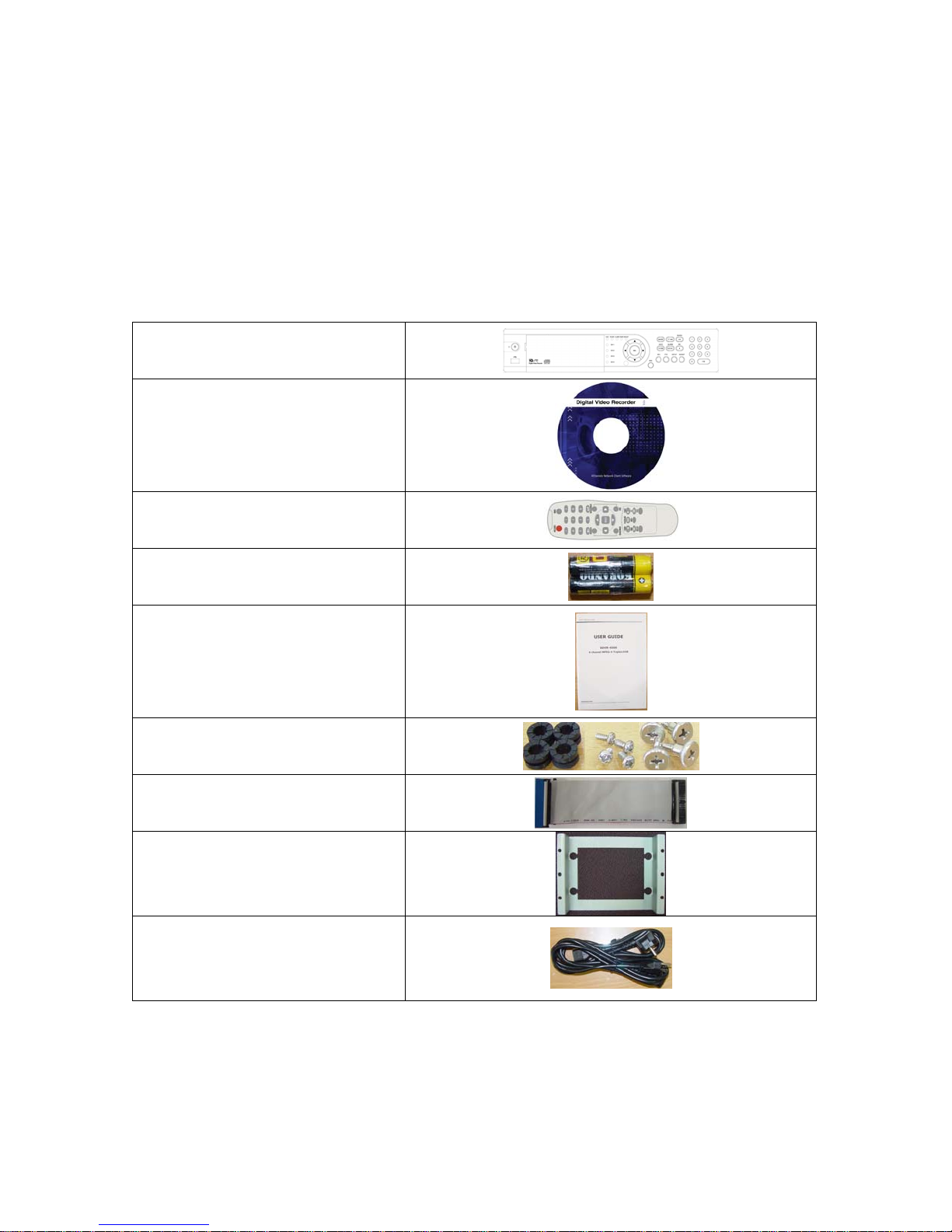
THE LIST OF CONTENTS
The package contains the DVR set and components as bellows. Please make sure that the
bellow components are included in the package. If there is any missing, please contact
your local vendor.
NETWORK CLIENT S/W CD
REMOTE CONTROLLER
BATTERY
DVR SET
MANUAL
RUBBER RINGS & SCREWS
FOR HDD INSTALLATION
IDE HDD CABLE
HDD BRACKET
POWER CABLE
4

Remote Control Operation
POWER
Power On/Off
DISPLAY
Display of Full, 4, 9 or 16 split view
F/REW
PLAY
F/ADV
FREEZE/CAP
FF
ALARM
SETUP
ARCHIVE
AUDIO
LOCK
SEQ
RECORD
SEARCH
DIRECTION
SELECT
ID
ESC
PTZ
NUMBER
+10
Jump 1 minute backward
Play/Pause
Jump 1 minute forward
Freeze/Capture
Fast Forward
Disable alarm operation
Setup menu screen
Display archive list
Disable, Mute or Highlighted
channel only
Locks functions
Sequence of Full or Quad view
Manual recording
Search menu screen
Direction or number 1 to 4
Enter
DVR ID
(ID Button + DVR ID number)
Esc
PTZ menu screen
Channel 1 to 9
Channel 10 and channel 11 to16
10CH->press +10 and number 0
11CH->press +10 and number 1
12CH->press +10 and number 2
13CH->press +10 and number 3
14CH->press +10 and number 4
15CH->press +10 and number 5
16CH->press +10 and number 6
5
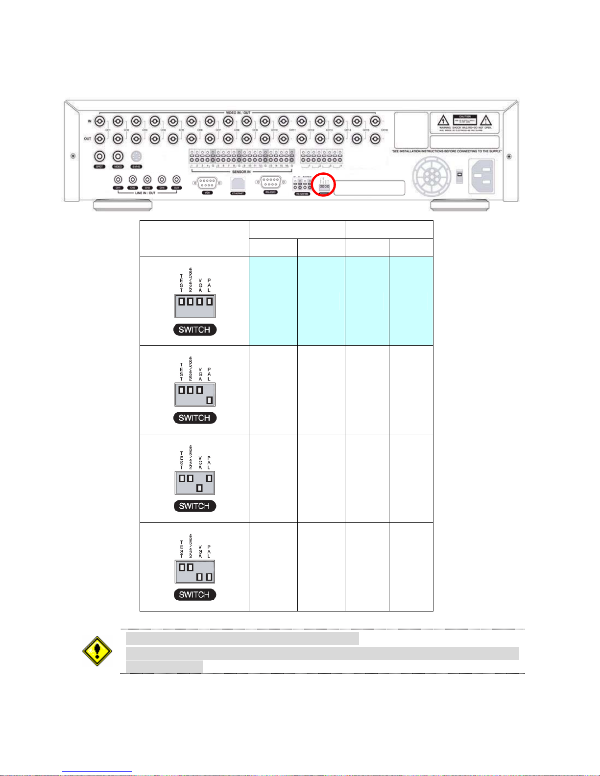
VIDEO SIGNAL SELECT / SETTING
SETTING
Video mode Video output
NTSC PAL BNC VGA
O X O X
X O O X
O X X O
Do not change the setting when the power is on.
When the position of the switch is changed, the DVR should be rebooted to apply
the new setting.
6
X O X O
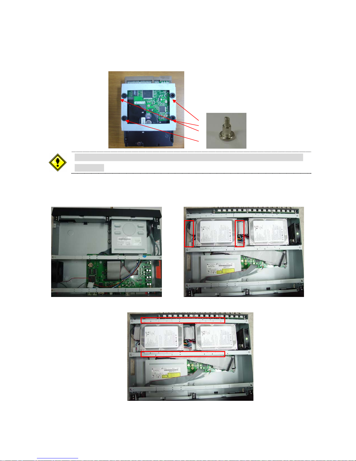
HDD INSTALLATION
Screw the HDD brackets to the HDD and insert rubber rings.
In case of installing two Hard Drives, one is to be set as “Master” and another is
as “Slave”.
Firmly insert IDE cable and power cable to the CD-RW Drive and HDD.
7
Fix the HDD to the chassis.
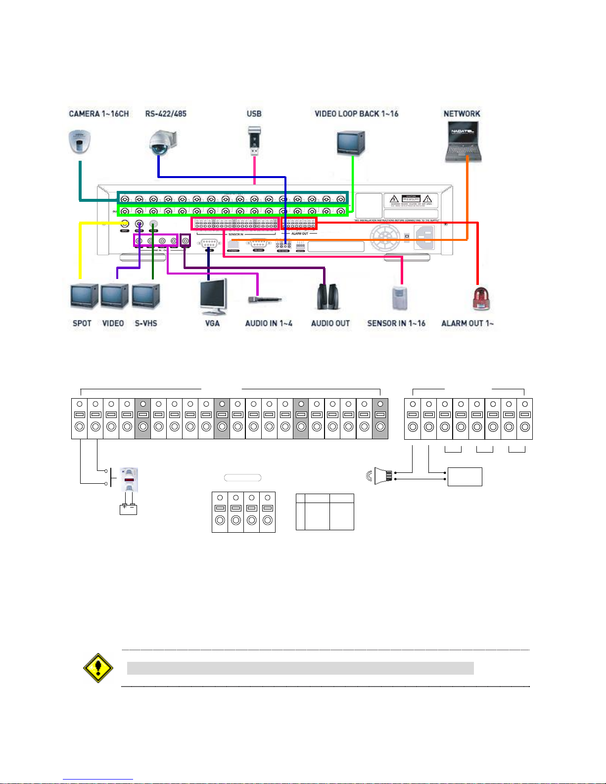
SYSTEM SCHEMETIC
Wiring Camera Control port and Sensor / Alarm Port
(+)
Alarm Out
2
(-)
34
+12VDC
12 34
Sensor
Dried Contact
Adapter
Sensor In(1~16)
G
5678G9101112G13 14 15 16
RS-422/485
TX+
TX- RX+
1 2 3 4
RX-
RS422 R485
1 TX+
2 TX3 RX+ DATA+
4 RX- DATA-
G
ABABABAB
1
(-)
(+)
SENSOR INPUT: Connect two signal lines of sensor to the desired sensor number. (You can set the type-NC
or NO- of sensor at “Setup” mode).
ALARM OUTPUT: Use this at 30V/300mA or less operating voltage and current.
When controlling lamp and AC operated equipment, control it using separate outside relay.
During normal operation the control output contact is maintained at “Open” status, and during control
output the output contact is changed to “Close (short)” status.
SENSOR inputs need dried contact only. Do not input any electric signal.
8
TABLE OF CONTENTS

1. FEATURES................................................................................................................................................9
2. FRONT / REAR PANEL...........................................................................................................................10
2-1. FRONT PANEL.............................................................................................................................13
2-2. REAR PANEL...............................................................................................................................15
3. SETUP.....................................................................................................................................................16
3-1. Entering SETUP...........................................................................................................................16
3-2. LIVE..............................................................................................................................................18
3-3. RECORD......................................................................................................................................19
3-3-1. Motion Zones ....................................................................................................................20
3-3-2. Recording Schedule..........................................................................................................20
3-4. DEVICE........................................................................................................................................22
3-4-1. ALARM OUT .....................................................................................................................23
3-4-2. PTZ....................................................................................................................................23
3-4-3. SPOT OUT........................................................................................................................24
3-5. SYSTEM.......................................................................................................................................25
3-6. SECURITY ...................................................................................................................................27
3-7. NETWORK...................................................................................................................................28
3-7-1. PORT ................................................................................................................................28
3-7-2. NETWORK TYPE .............................................................................................................29
3-7-3. DDNS................................................................................................................................31
3-8 STORAGE.....................................................................................................................................32
3-9. SAVE SETUP...............................................................................................................................32
4. LIVE & SEARCH .....................................................................................................................................33
4-1. Live Screen ..................................................................................................................................33
4-2. SEARCH ......................................................................................................................................34
4-2-1. TIME LINE Search ............................................................................................................35
4-2-2. EVENT Search..................................................................................................................35
4-2-3. GO TO SPECIFIC TIME....................................................................................................37
4-2-4. GO TO FIRST TIME..........................................................................................................37
4-2-5. GO TO LAST TIME...........................................................................................................37
4-2-6. LOG...................................................................................................................................37
4-2-7. ARCHIVE...........................................................................................................................39
4-3. Playback mode.............................................................................................................................40
4-4. PTZF operation ............................................................................................................................41
5. Archiving Video into CD-RW or USB storage device ..............................................................................42
5-1. Archiving images or videos ................................................................................................
9
..........42

5-1-1. Archive images in live mode .............................................................................................42
5-1-2. Archive images in playback mode.....................................................................................42
5-1-3. Archive videos...................................................................................................................43
5-2. Transferring still images or videos into CD-RW or USB memory stick ........................................44
6. Network Client Software..........................................................................................................................45
6-1. Overview ......................................................................................................................................45
6-2. Minimum PC requirements...........................................................................................................45
6-3. Installing the software...................................................................................................................46
6-4. Live viewer ...................................................................................................................................46
6-4-1. Main user interface............................................................................................................46
6-4-2. Main control panel.............................................................................................................47
6-5. Search and Playback Viewer .......................................................................................................48
6-5-1. Main user interface............................................................................................................48
6-5-2. Main control panel.............................................................................................................49
6-5-3. Back up .............................................................................................................................50
6-6. System configuration....................................................................................................................51
6-6-1. General..............................................................................................................................51
6-6-2. Site....................................................................................................................................52
6-6-3. Event.................................................................................................................................53
6-6-4. Record...............................................................................................................................54
6-6-5. Disk ...................................................................................................................................55
6-6-6. About.................................................................................................................................55
7. Firmware Upgrade...................................................................................................................................56
A-1. DDNS (Dynamic Domain Name Server)......................................................................................57
A-1-1. Creating an ID and password on our free DDNS Service................................................57
A-1-2. Domain Name Registration ..............................................................................................58
A-1-3. Access to DVR by Domain Name.....................................................................................60
A-1-4. Domain Name Management.............................................................................................60
A-2. Compatible HDD models .............................................................................................................62
A-3. Specifications...............................................................................................................................63
10

1. FEATURES
● 9/16 channels real-time live display and 9/16 channels simultaneous playback.
● MPEG-4 - Unbeatable recording picture quality and compression ratio. Best format for minimizing
recording space and bandwidth requirements for network transmission.
● TRIPLEX - Simultaneous recording, playback and transmission via network
● Multiplexing operation
● Reliability - Real Time Operating System and simplified hardware as well as watchdog timer
ensure reliability.
● Individual channel recording and playback with different frame rate.
● High-quality live and playback resolution.
● Multi-site management - Supported by CMS application.
● Network features - remote live, playback, PTZF control and backup.
● Network via LAN, DHCP and ADSL (Dynamic and Static IP address).
● 4 channels audio recording.
● User-friendly setup menu with graphic user interface.
● Easy to schedule complicated weekly recording plans.
● Motion detection – Use the 30x24 grid to define motion zones for each camera.
● USB ports for JPEG, MPEG data backup and software upgrade using USB flash memory stick.
● Still image capture and review as JPEG format.
11

● Internal Pan/Tilt/Zoom/Focus controller.
● Easy operation with buttons on the front panel and an optional remote control.
● User verification by password certification.
● Video loss detection.
● Backup - Still-images or AVI data into USB flash memory stick, internal CD-RW and Network.
● Variety of Hard Drive Sizes - up to internally 1TB (500GB HDD X 2) for long-term recording.
● Multi-Languages -User can easily select language from Setup menu.
● Various Video Output - VGA(800x600 24 Bit Color), S-VHS, SPOT
12
2. FRONT / REAR PANEL
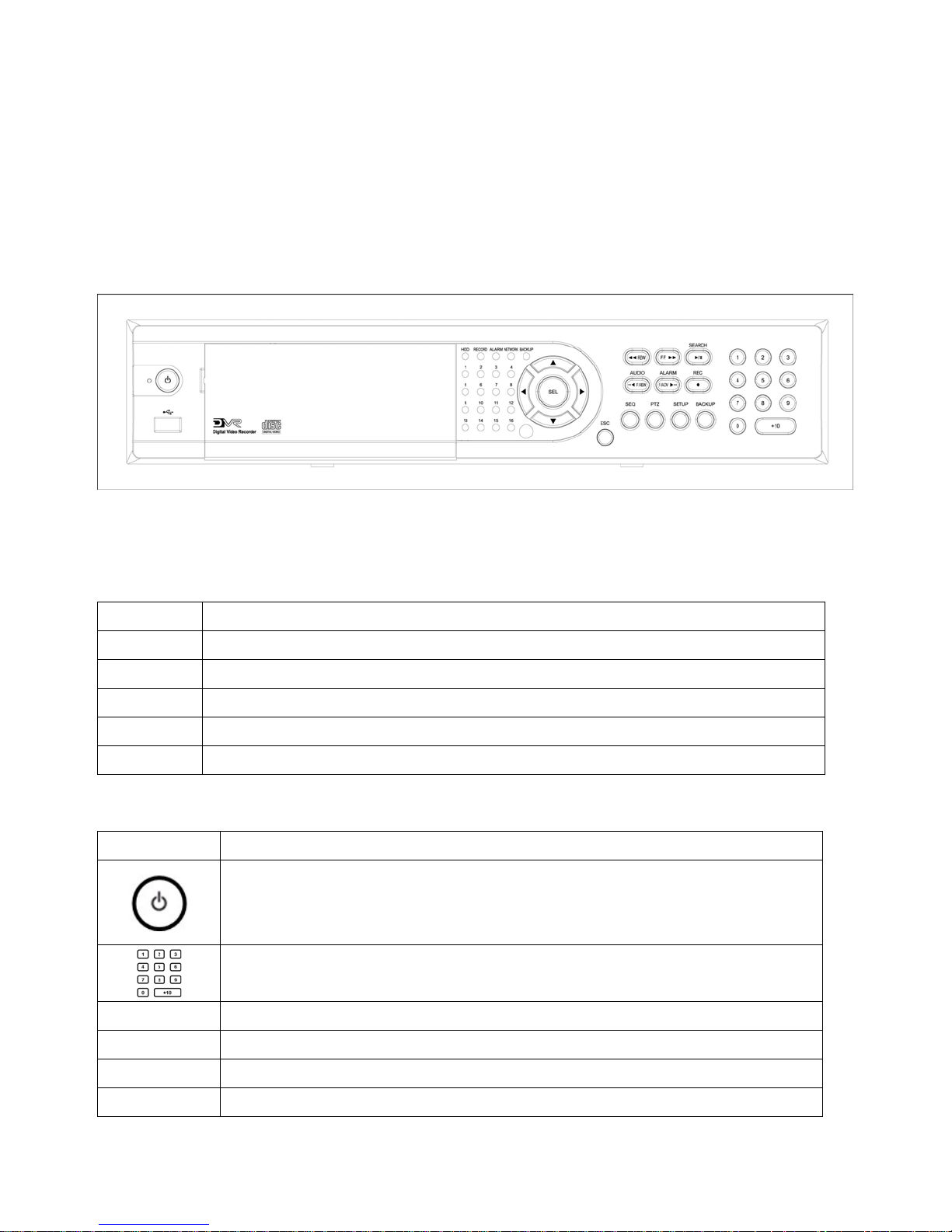
2-1. FRONT PANEL
Figure 2.1.1 Front panel
Table 2.1.1 LED Indication
LED Description
HDD
REC
ALARM
NETWORK
BACKUP
Table 2.1.2 Front panel buttons
Button Description
SEQ
LED light is on when the system is accessing video data.
LED light is on when the system is recording video data.
LED light is on when alarm sensors are triggered or motion is detected.
LED light is on when clients are connected to the system through the network.
LED light is on when the system save an image to a USB stick or a CD.
Power ON/OFF button. Press to start the DVR system or to do shutdown.
When you turn off the DVR system, it will ask for a password. The default
password is 1111.
Press to select a channel number or password. Press the +10 button and a
number for selecting a channel number 10 to 16.
Press to start auto sequencing of the screen in full or quad view. (Toggle)
PTZ
SETUP
BACKUP
13
Press to control PTZ operation in live display mode.
Press to launch SETUP menu.
Press to start operations involving archiving in live or playback mode.

Press to rewind the video at 1x, 2x, 4x and 8x speed in playback mode.
Jump/Step backward in playback mode, the playback position moves 1
minute backward. Sound function in live display mode.(MUTE, Selected
channel or All channel sound)
Jump/Step forward in playback mode, the playback position moves 1 minute
forward. Alarm out function ON/OFF in live display mode.
Press to fast forward the video at 1x, 2x, 8x and 4x speeds in playback
mode.
Press to go to the search menu. (Event search /Time line search /Log
/Archive search) Press to play/pause the video in playback mode.
Press to start and stop manual recording.
Press to move up the menu items in setup mode and to select camera 1 in
live mode. It is also used as the number 1 when entering password.
Press to move right in the menu or to change the values in setup mode and
USB Port
to select camera 2 in live mode. It is also used as the number 2 when
entering password.
Press to move down the menu items in setup mode and to select camera 3 in
live mode. It is also used as the number 3 when entering password.
Press to move left in the menu or to change the values in setup mode and to
select camera 4 in live mode. It is also used as the number 4 when entering
password.
Press to select full screen or 4/ 9/ 16 split view in live display mode. It is also
used to select desired menu item or to store the setup value in the menu.
Press to return to previous menu screen.
There is a USB port located on the left side of the front panel. This USB port
is used to archive video into a USB memory stick and USB CD-RW.
14
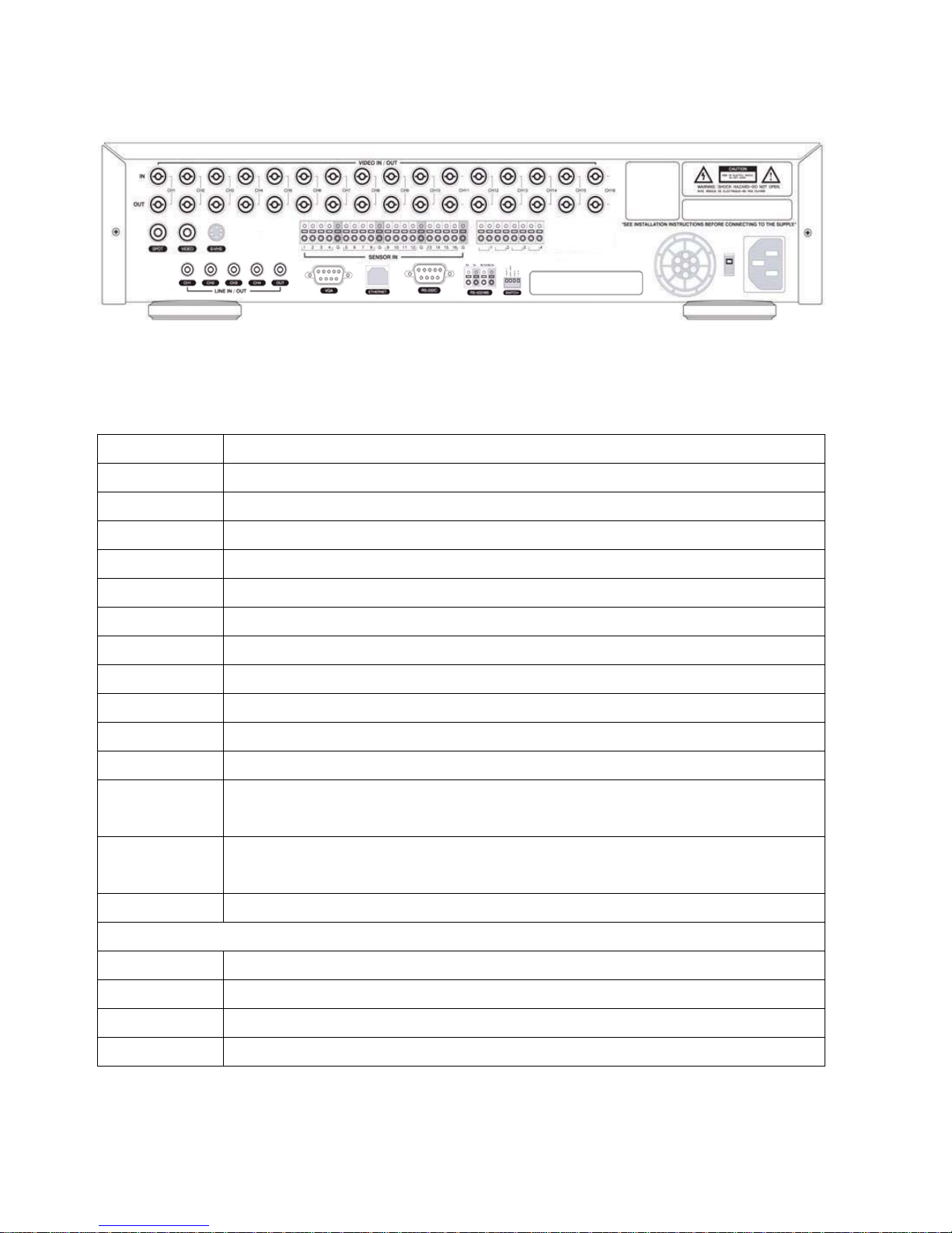
2-2. REAR PANEL
Figure 2.2.1 Rear Panel
Table 2.2.1 Rear panel connections
TITLE Description
VIDEO IN
VIDEO OUT
SPOT
VIDEO
S-VHS
VGA
AUDIO IN
AUDIO OUT
RS-232
LAN
RS-485/422
SENSOR IN
ALARM OUT
POWER
Connectors for video inputs(NTSC/PAL)
Connectors for video loop back outputs(NTSC/PAL)
Connector for video spot output(NTSC/PAL)
Composite video output(NTSC/PAL)
S-VHS video output
Connector for VGA monitor
Four connectors for audio inputs(line level)
One connector for audio output(connect a headphone or a speaker)
For engineering use only
RJ45 connector for LAN connection
For camera control use
Connector for sensor device connection. Normal open (NO) or normal close
(NC) sensor can be selected for each sensor.
Connector for alarm device connection. Provides simple On/Off switching
using relay. 0.5A/125V, 1A/30V
AC115~230V power input
SWITCHES : NTSC/PAL, BNC/VGA Select switch
TEST
485/422
VGA
PAL
For future use
Selection of VGA monitor or Composite monitor
Video type selection of NTSC or PAL
15
3. SETUP
The following sections detail the initial setup of the DVR.
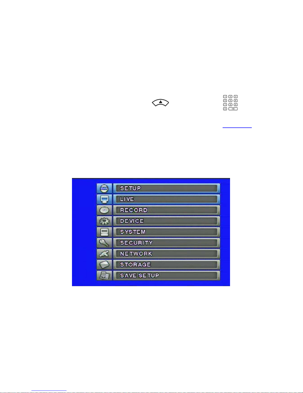
3-1. Entering SETUP
When you press the SETUP button, the DVR will ask for a password. The default password is 1111,
which can be entered by pressing the up button (
then pressing the SEL button. We recommend you protect the system by assigning a new
password immediately. The procedure for assigning a password is found in section 3-6.
password has been assigned, enter the password by using the 4 direction buttons or number
buttons, and then press the SEL button for password validation. Once the password is entered, you
will see the screen as shown in Figure 3.1.1. Navigate through the menu items and press the SEL
button to enter the sub-category menu.
) or number 1 button ( ) 4 times and
After a
16
Figure 3.1.1 Setup menu screen

▶ Setup menu configuration
SETUP LIVE OSD
SEQUENCE
SEQ-DWELL TIME
OSD CONTRAST
CHANNEL DISPLAY, BRIGHTNESS, CONTRAST, HUE,
RECORD RESOLUTION SATURATION
CHANNEL FRAME, QUALITY, TYPE, MOTION, SENSOR,
SENSITIVITY, PRE/POST RECORDING, SCHEDULE
DEVICE ALARM-OUT
PTZ
SPOT-OUT
KEY TONE
REMOTE CONTROL ID
SENSOR TYPE
SYSTEM DVR ID
DESCRIPTION
LANGUAGE
LOAD FACTORY DEFAULT
LOAD DEFAULT
DATE FORMAT
SET DATE & TIME
SECURITY ADMIN PASSWORD
USER PASSWORD
NETWORK PASSWORD
NETWORK PORT
CLIENT ACCESS
BANDWIDTH SAVING
NETWORK TYPE – LAN, ADSL, DHCP
DDNS
STORAGE OVERWRITE
FORMAT
DISK INFO
LOAD SETUP FROM A USB
SAVE SETUP TO A USB
RECORD LIMIT
SAVE SETUP
17
RECORD LIMIT DAYS
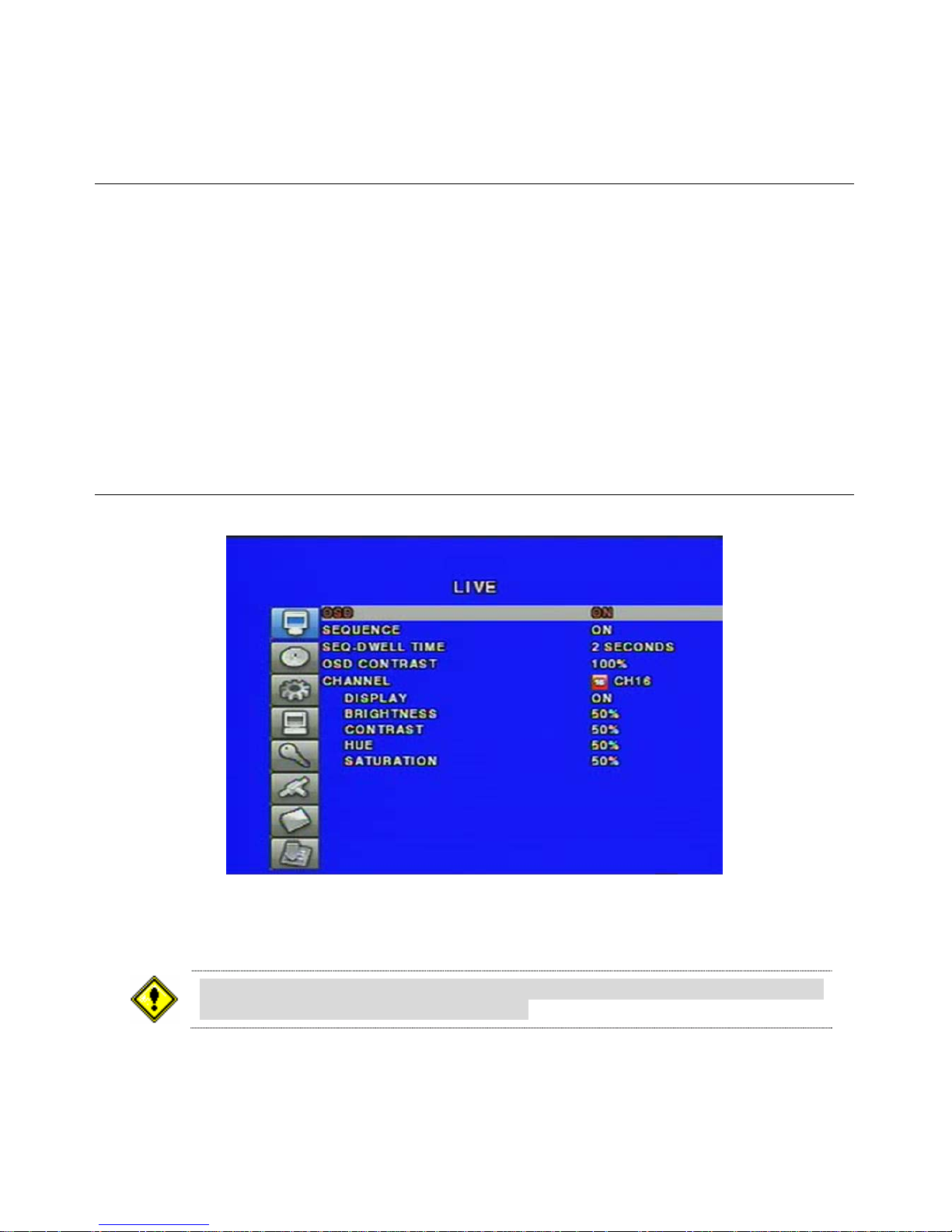
3-2. LIVE
Set values for live display. Navigate through the menu items by pressing the UP/DOWN buttons.
Menu items in LIVE mode setup
OSD: Enable/disable on-screen-display.
SEQUENCE: Enable/disable auto sequencing of the screen in full or quad view.
SEQ-DWELL TIME: Dwell time for each channel display in sequential display mode.
OSD CONTRAST: Set the visibility level of the On Screen Display. (OSD)
CHANNEL: Select the channel for applying the following settings by pressing the LEFT/RIGHT
buttons.
DISPLAY: Enable/disable display of the video channel in live display mode.
BRIGHTNESS: Change the brightness value for the specified channel.
CONTRAST: Change the contrast value for the specified channel.
HUE: Change the hue value for the specified channel.
SATURATION: Change the saturation value for the specified channel.
If the values of BRIGHTNESS, CONTRAST, HUE, & SATURATION is changed, the
video will be recorded as same as changed.
18
Figure 3.2.1 LIVE mode setup screen

3-3. RECORD
Set the values for recording video. Navigate through menu items by pressing the UP/DOWN
buttons. User can change the value of the menu item by pressing the LEFT/RIGHT buttons.
Menu items in RECORD mode setup
RESOLUTION: Set resolution. (360*240, 720*240 or 720*480)
CHANNEL: Select the channel for applying the following settings.
FRAME RATE: Set the frame rate. The sum of the frame rate values from each channel cannot
exceed maximum frame rates for a particular recording resolution. Typical values of the maximum
frame rate for NTSC video are 120/100 fps for 360*240(NTSC)/360*288(PAL) and 30/25fps for
720*480(NTSC)/720*576(PAL).
QUALITY: Select the recording quality for the specified channel.
[Network, Standard, High, Superior and Ultra]
RECORDING: Assign the recording mode for each channel.
[Continuous, Motion, Sensor, Schedule, and Disable]
MOTION ZONE: Select Full Zone or Partial Zone for motion sensing.
Press SEL button to setup motion sensing area.
MOTION SENSITIVITY: Set the motion sensitivity. Control the motion sensitivity from 1 to 9.
SENSOR RECORDING: Select sensors to record for the specified channel.
You can set the sensor type from DEVICE setup menu. (N/O or N/C)
PRE RECORD: Enable/disable pre-event recording. Pre-event recording time is 5 seconds
and only intra-frames are recorded for pre-event recording.
POST EVENT RECORD: Set post event recording time duration. (2 ~ 30 seconds)
AUDIO: Enable/disable audio for the specified channel.
SCHEDULE: Set recording schedule. Press SEL button to setup schedule.
Figure 3.3.1 RECORD mode setup screen
19

3-3-1. Motion Zones
By selecting Partial Zone in the Motion Zone menu, users can set-up the motion sensing zones in
the screen shown in figure 3.3.2. Move around each rectangular zone using 4 direction key buttons
and press SEL button to include the rectangular region as part of the motion sensing zone. The
rectangular blocks included as part of the motion zone are indicated by changing the color of the
blocks.
Figure 3.3.2 Motion Zone selection screen
3-3-2. Recording Schedule
Select SCHEDULE in the RECORD menu to set up the recording schedule. Navigate through the
items to highlight using the 4 direction key buttons and set recording schedule using the SEL button.
Recording mode in schedule
COPY FROM: Select a channel number by pressing the LEFT/RIGHT buttons.
And press SEL button to make the same schedule as the selected channel.
COPY TO: Select a channel number by pressing the LEFT/RIGHT buttons.
And press SEL button to make selected channel to the same schedule as this schedule.
[ALL]: When ALL is highlighted, selected recording mode by pressing SEL button is applied to
entire time zone for the specified channel.
[DAY]: When a particular DAY of week is highlighted, selected recording mode by pressing SEL
button is applied to entire day zone for the specified channel.
20
 Loading...