


DIGITAL VIDEO RECORDER
PXE Series
Server
Operation Manual
Please read these instructions and save this manual for future use
www.cascadiadvrt.com / (888) 421-0050
1

SAFETY INSTRUCTIONS
CAUTION:
TO REDUCE THE RISK OF ELECTRIC SHOCK,
DO NOT REMOVE COVER (OR BACK).
NO USER-SERVICEABLE PARTS INSIDE.
REFER SERVICING TO QUALIFIED SERVICE PERSONNEL.
THIS PRODUCT HAS MULTIPLE-RATED VOLTAGES.
ADJUST POWER INPUT SELECTOR SWITCH PROPERLY ON REAR OF UNIT BEFORE CONNECTING TO
THE POWER SUPPLY.
1) Read these instructions.
2) Keep these instructions.
3) Heed all warnings.
4) Follow all instructions.
5) Do not use this apparatus near water.
6) Clean only with dry cloth.
7) Do not block any ventilation openings. Install in accordance with the manufacturer's instructions.
8) Do not use near any heat sources such as radiators, heat registers, stoves, or other apparatus (including
amplifiers) that produce heat.
9) Do not defeat the safety purpose of the polarized or grounding-type plug. A polarized plug has two blades
with one wider than the other. A grounding-type plug has two blades and a third grounding prong. The wide
blade or the third prong are
provided for your safety. If the provided plug does not fit into your outlet, consult an electrician for
replacement of the obsolete outlet.
10) Protect the power cord from being walked on or pinched particularly at plugs, convenience receptacles
and the points where they exit from the apparatus.
11) Only use attachments/accessories specified by the manufacturer.
12) Use only with the cart, stand, tripod, bracket, or table specified by the manufacturer, or sold with the
apparatus.
13) Unplug this apparatus during lightning storms or when unused for long periods of time.
14) Refer all servicing to qualified service personnel. Servicing is required when the apparatus has been
damaged in any way, such as power-supply cord or plug is damaged, liquid has been spilled or objects fallen
into the apparatus, the apparatus has been exposed to rain or moisture, does not operat e normally, or has
been dropped.
NOTE: This equipment has been tested and found to comply with the limits for a Class A digital device, pursuant
to part 15 of the FCC rules These limits are designed to provide reasonable protection against harmful
interference when the equipment is operated in a commercial environment This equipment generates, uses, and
can radiate radio frequency energy and, if not installed and used in accordance with the instruction manual, may
cause harmful interference to radio communications Operation of this equipment in a residential area is likely to
cause harmful interference in which case the user will be required to correct the interference at his own expense
IMPORTANT The only way to disconnect power completely is to unplug the power cord
Make sure at least one end of the power cord is within easy reach so that you can unplug the computer when
you need to
CAUTION: DANGER OF EXPLOSION IF BATTERY IS INCORRECTLY REPLACED REPLACE ONLY WITH THE SAME
OR EQUIVALENT TYPE RECOMMENDED BY THE MANUFACTURER DISCARD USED BATTERIES ACCORDING TO
THE MANUFACTURER’S INSTRUCTIONS
WARNING:
To prevent fire or electric shock hazard, do not expose this appliance to rain or moisture. The apparatus shall
not be exposed to dripping or splashing and that no objects filled with liquids, such as vases, shall be placed
on the apparatus.
www.cascadiadvrt.com / (888) 421-0050
2

Table of Contents
61. LAYOUT ㅡㅡㅡㅡㅡㅡㅡㅡㅡㅡㅡㅡㅡㅡㅡㅡㅡㅡㅡㅡㅡㅡㅡㅡㅡㅡㅡㅡㅡㅡㅡㅡㅡ
7FRONT VIEW ㅡㅡㅡㅡㅡㅡㅡㅡㅡㅡㅡㅡㅡㅡㅡㅡㅡㅡㅡㅡㅡㅡㅡㅡㅡㅡㅡㅡ
8REAR VIEW ㅡㅡㅡㅡㅡㅡㅡㅡㅡㅡㅡㅡㅡㅡㅡㅡㅡㅡㅡㅡㅡㅡㅡㅡㅡㅡㅡ
82. DISPLAY ㅡㅡㅡㅡㅡㅡㅡㅡㅡㅡㅡㅡㅡㅡㅡㅡㅡㅡㅡㅡㅡㅡㅡㅡㅡㅡㅡㅡㅡㅡㅡㅡ
10SYSTEM ㅡㅡㅡㅡㅡㅡㅡㅡㅡㅡㅡㅡㅡㅡㅡㅡㅡㅡㅡㅡㅡㅡㅡㅡㅡㅡㅡ
11DISPLAY ㅡㅡㅡㅡㅡㅡㅡㅡㅡㅡㅡㅡㅡㅡㅡㅡㅡㅡㅡㅡㅡㅡㅡㅡㅡㅡㅡㅡㅡ
12AUDIO ㅡㅡㅡㅡㅡㅡㅡㅡㅡㅡㅡㅡㅡㅡㅡㅡㅡㅡㅡㅡㅡㅡㅡㅡㅡㅡㅡㅡㅡ
12ALARM ㅡㅡㅡㅡㅡㅡㅡㅡㅡㅡㅡㅡㅡㅡㅡㅡㅡㅡㅡㅡㅡㅡㅡㅡㅡㅡㅡㅡ
12PTZ ㅡㅡㅡㅡㅡㅡㅡㅡㅡㅡㅡㅡㅡㅡㅡㅡㅡㅡㅡㅡㅡㅡㅡㅡㅡㅡㅡㅡㅡ
13CONTROL ㅡㅡㅡㅡㅡㅡㅡㅡㅡㅡㅡㅡㅡㅡㅡㅡㅡㅡㅡㅡㅡㅡㅡㅡㅡㅡㅡㅡㅡ
14V-OUTPUT ㅡㅡㅡㅡㅡㅡㅡㅡㅡㅡㅡㅡㅡㅡㅡㅡㅡㅡㅡㅡㅡㅡㅡㅡㅡㅡㅡㅡㅡ
14LOG VIEW ㅡㅡㅡㅡㅡㅡㅡㅡㅡㅡㅡㅡㅡㅡㅡㅡㅡㅡㅡㅡㅡㅡㅡㅡㅡㅡㅡㅡ
153. SETUP ㅡㅡㅡㅡㅡㅡㅡㅡㅡㅡㅡㅡㅡㅡㅡㅡㅡㅡㅡㅡㅡㅡㅡㅡㅡㅡㅡㅡㅡㅡㅡㅡ
TIME ㅡㅡㅡㅡㅡㅡㅡㅡㅡㅡㅡㅡㅡㅡㅡㅡㅡㅡㅡㅡㅡㅡㅡㅡㅡㅡㅡㅡ
UPGRADE ㅡㅡㅡㅡㅡㅡㅡㅡㅡㅡㅡㅡㅡㅡㅡㅡㅡㅡㅡㅡㅡㅡㅡㅡㅡㅡㅡㅡ
DISK ㅡㅡㅡㅡㅡㅡㅡㅡㅡㅡㅡㅡㅡㅡㅡㅡㅡㅡㅡㅡㅡㅡㅡㅡㅡㅡㅡㅡㅡㅡㅡㅡ
ETC ㅡㅡㅡㅡㅡㅡㅡㅡㅡㅡㅡㅡㅡㅡㅡㅡㅡㅡㅡㅡㅡㅡㅡㅡㅡㅡㅡㅡㅡㅡㅡㅡ
16CAMERA ㅡㅡㅡㅡㅡㅡㅡㅡㅡㅡㅡㅡㅡㅡㅡㅡㅡㅡㅡㅡㅡㅡㅡㅡㅡㅡㅡㅡㅡㅡ
17RECORD ㅡㅡㅡㅡㅡㅡㅡㅡㅡㅡㅡㅡㅡㅡㅡㅡㅡㅡㅡㅡㅡㅡㅡㅡㅡㅡㅡㅡㅡ
18SCHEDULE ㅡㅡㅡㅡㅡㅡㅡㅡㅡㅡㅡㅡㅡㅡㅡㅡㅡㅡㅡㅡㅡㅡㅡㅡㅡㅡㅡ
19MOTION ㅡㅡㅡㅡㅡㅡㅡㅡㅡㅡㅡㅡㅡㅡㅡㅡㅡㅡㅡㅡㅡㅡㅡㅡㅡㅡㅡㅡㅡㅡ
19SENSOR ㅡㅡㅡㅡㅡㅡㅡㅡㅡㅡㅡㅡㅡㅡㅡㅡㅡㅡㅡㅡㅡㅡㅡㅡㅡㅡㅡ
20ALARM ㅡㅡㅡㅡㅡㅡㅡㅡㅡㅡㅡㅡㅡㅡㅡㅡㅡㅡㅡㅡㅡㅡㅡㅡㅡㅡㅡㅡㅡ
21NETWORK ㅡㅡㅡㅡㅡㅡㅡㅡㅡㅡㅡㅡㅡㅡㅡㅡㅡㅡㅡㅡㅡㅡㅡㅡㅡㅡㅡ
23STORAGE ㅡㅡㅡㅡㅡㅡㅡㅡㅡㅡㅡㅡㅡㅡㅡㅡㅡㅡㅡㅡㅡㅡㅡㅡㅡㅡㅡㅡㅡ
24USER ㅡㅡㅡㅡㅡㅡㅡㅡㅡㅡㅡㅡㅡㅡㅡㅡㅡㅡㅡㅡㅡㅡㅡㅡㅡㅡㅡㅡ
25POS ㅡㅡㅡㅡㅡㅡㅡㅡㅡㅡㅡㅡㅡㅡㅡㅡㅡㅡㅡㅡㅡㅡㅡㅡㅡㅡㅡ
26SYSTEM ㅡㅡㅡㅡㅡㅡㅡㅡㅡㅡㅡㅡㅡㅡㅡㅡㅡㅡㅡㅡㅡㅡㅡㅡㅡㅡㅡㅡㅡㅡ
284. A/S SETUP ㅡㅡㅡㅡㅡㅡㅡㅡㅡㅡㅡㅡㅡㅡㅡㅡㅡㅡㅡㅡㅡㅡㅡㅡㅡㅡㅡㅡㅡ
29
29
29
29
CHECK ㅡㅡㅡㅡㅡㅡㅡㅡㅡㅡㅡㅡㅡㅡㅡㅡㅡㅡㅡㅡㅡㅡㅡㅡㅡㅡㅡㅡㅡㅡㅡ
www.cascadiadvrt.com / (888) 421-0050
29
3

Table of Contents (cont.)
305. SEARCH ㅡㅡㅡㅡㅡㅡㅡㅡㅡㅡㅡㅡㅡㅡㅡㅡㅡㅡㅡㅡㅡㅡㅡㅡㅡㅡㅡㅡㅡ
CALENDAR ㅡㅡㅡㅡㅡㅡㅡㅡㅡㅡㅡㅡㅡㅡㅡㅡㅡㅡㅡㅡㅡㅡㅡㅡㅡㅡ
VIDEO MAP ㅡㅡㅡㅡㅡㅡㅡㅡㅡㅡㅡㅡㅡㅡㅡㅡㅡㅡㅡㅡㅡㅡㅡㅡㅡ
EXPORT IMG ㅡㅡㅡㅡㅡㅡㅡㅡㅡㅡㅡㅡㅡㅡㅡㅡㅡㅡㅡㅡㅡㅡㅡㅡㅡㅡ
EXPORT AVI ㅡㅡㅡㅡㅡㅡㅡㅡㅡㅡㅡㅡㅡㅡㅡㅡㅡㅡㅡㅡㅡㅡㅡㅡㅡㅡㅡㅡ
SMART ㅡㅡㅡㅡㅡㅡㅡㅡㅡㅡㅡㅡㅡㅡㅡㅡㅡㅡㅡㅡㅡㅡㅡㅡㅡㅡㅡ
HOW TO UPGRADE ㅡㅡㅡㅡㅡㅡㅡㅡㅡㅡㅡㅡㅡㅡㅡㅡㅡㅡㅡㅡㅡㅡㅡㅡ 36
MANUAL RECORDING ㅡㅡㅡㅡㅡㅡㅡㅡㅡㅡㅡㅡㅡㅡㅡㅡㅡㅡㅡㅡㅡㅡㅡ
SCHEDULE RECORDING ㅡㅡㅡㅡㅡㅡㅡㅡㅡㅡㅡㅡㅡㅡㅡㅡㅡㅡㅡㅡㅡ
NORMAL SEARCH ㅡㅡㅡㅡㅡㅡㅡㅡㅡㅡㅡㅡㅡㅡㅡㅡㅡㅡㅡㅡㅡㅡㅡㅡㅡ
31
31
32
32
32
336. QUICK USE 1 ㅡㅡㅡㅡㅡㅡㅡㅡㅡㅡㅡㅡㅡㅡㅡㅡㅡㅡㅡㅡㅡㅡㅡㅡㅡㅡㅡㅡㅡㅡㅡ
34TIME/DATE ADJUSTMENT ㅡㅡㅡㅡㅡㅡㅡㅡㅡㅡㅡㅡㅡㅡㅡㅡㅡㅡㅡㅡㅡ
35DVR/REMOTE CONTROLLER ID SETUP ㅡㅡㅡㅡㅡㅡㅡㅡㅡㅡㅡㅡㅡㅡㅡ
377. QUICK USE 2 ㅡㅡㅡㅡㅡㅡㅡㅡㅡㅡㅡㅡㅡㅡㅡㅡㅡㅡㅡㅡㅡㅡㅡㅡㅡㅡㅡㅡㅡㅡㅡ
38
39
408. QUICK USE 3 ㅡㅡㅡㅡㅡㅡㅡㅡㅡㅡㅡㅡㅡㅡㅡㅡㅡㅡㅡㅡㅡㅡㅡㅡㅡㅡㅡㅡㅡㅡㅡ
41
SMART SEARCH ㅡㅡㅡㅡㅡㅡㅡㅡㅡㅡㅡㅡㅡㅡㅡㅡㅡㅡㅡㅡㅡㅡㅡㅡㅡ
TEXT SEARCH ㅡㅡㅡㅡㅡㅡㅡㅡㅡㅡㅡㅡㅡㅡㅡㅡㅡㅡㅡㅡㅡㅡㅡㅡㅡㅡ
www.cascadiadvrt.com / (888) 421-0050
4
42
43
449. QUICK USE 4 ㅡㅡㅡㅡㅡㅡㅡㅡㅡㅡㅡㅡㅡㅡㅡㅡㅡㅡㅡㅡㅡㅡㅡㅡㅡㅡㅡㅡㅡㅡㅡ
45JPG, BMP, AVI SAVE ㅡㅡㅡㅡㅡㅡㅡㅡㅡㅡㅡㅡㅡㅡㅡㅡㅡㅡㅡㅡㅡㅡㅡㅡㅡ
46BACKUP ㅡㅡㅡㅡㅡㅡㅡㅡㅡㅡㅡㅡㅡㅡㅡㅡㅡㅡㅡㅡㅡㅡㅡㅡㅡㅡㅡㅡㅡ
4710. QUICK USE 5 ㅡㅡㅡㅡㅡㅡㅡㅡㅡㅡㅡㅡㅡㅡㅡㅡㅡㅡㅡㅡㅡㅡㅡㅡㅡㅡㅡㅡㅡㅡㅡ
48IP SETTING/CONNECTING ㅡㅡㅡㅡㅡㅡㅡㅡㅡㅡㅡㅡㅡㅡㅡㅡㅡㅡㅡㅡㅡㅡㅡ
50DDNS/WEB VIEWER CONNECTING ㅡㅡㅡㅡㅡㅡㅡㅡㅡㅡㅡㅡㅡㅡㅡㅡㅡㅡㅡ
51PDNS CONNECTING ㅡㅡㅡㅡㅡㅡㅡㅡㅡㅡㅡㅡㅡㅡㅡㅡㅡㅡㅡㅡㅡㅡㅡㅡㅡ
53E-MAIL SETTING/NOTIFICATION ㅡㅡㅡㅡㅡㅡㅡㅡㅡㅡㅡㅡㅡㅡㅡㅡㅡㅡㅡㅡ
54USER PASSWORD SETTING ㅡㅡㅡㅡㅡㅡㅡㅡㅡㅡㅡㅡㅡㅡㅡㅡㅡㅡㅡㅡㅡㅡ

Table of Contents (cont.)
5511. QUICK USE 6 ㅡㅡㅡㅡㅡㅡㅡㅡㅡㅡㅡㅡㅡㅡㅡㅡㅡㅡㅡㅡㅡㅡㅡㅡㅡㅡㅡㅡㅡ
PRESET/EVENT TRACKING ㅡㅡㅡㅡㅡㅡㅡㅡㅡㅡㅡㅡㅡㅡㅡㅡㅡㅡㅡㅡㅡㅡ
MOTION, SENSOR / ALARM SETTING ㅡㅡㅡㅡㅡㅡㅡㅡㅡㅡㅡㅡㅡㅡㅡㅡㅡㅡ
SENSOR CONNECTING ㅡㅡㅡㅡㅡㅡㅡㅡㅡㅡㅡㅡㅡㅡㅡㅡㅡㅡㅡㅡㅡㅡㅡㅡ
ALARM CONNECTING ㅡㅡㅡㅡㅡㅡㅡㅡㅡㅡㅡㅡㅡㅡㅡㅡㅡㅡㅡㅡㅡㅡㅡㅡ
EXTERNAL STORAGE CONNECTING ㅡㅡㅡㅡㅡㅡㅡㅡㅡㅡㅡㅡㅡㅡㅡㅡㅡㅡ
SURVEILLANCE ㅡㅡㅡㅡㅡㅡㅡㅡㅡㅡㅡㅡㅡㅡㅡㅡㅡㅡㅡㅡㅡㅡㅡㅡㅡㅡ
SEARCH ㅡㅡㅡㅡㅡㅡㅡㅡㅡㅡㅡㅡㅡㅡㅡㅡㅡㅡㅡㅡㅡㅡㅡㅡㅡㅡㅡㅡㅡ
56
57
59
60
61PTZ CONNECTING ㅡㅡㅡㅡㅡㅡㅡㅡㅡㅡㅡㅡㅡㅡㅡㅡㅡㅡㅡㅡㅡㅡㅡㅡㅡ
63POS SETTING ㅡㅡㅡㅡㅡㅡㅡㅡㅡㅡㅡㅡㅡㅡㅡㅡㅡㅡㅡㅡㅡㅡㅡㅡ
64
6512. CLIENT ㅡㅡㅡㅡㅡㅡㅡㅡㅡㅡㅡㅡㅡㅡㅡㅡㅡㅡㅡㅡㅡㅡㅡㅡㅡㅡㅡㅡㅡㅡㅡ
66CLIENT INSTALLATION/CONNECTION ㅡㅡㅡㅡㅡㅡㅡㅡㅡㅡㅡㅡㅡㅡㅡ
6713. CLIENT SURVEILLANCE ㅡㅡㅡㅡㅡㅡㅡㅡㅡㅡㅡㅡㅡㅡㅡㅡㅡㅡㅡㅡㅡㅡㅡㅡㅡ
68
7014. CLIENT SEARCH ㅡㅡㅡㅡㅡㅡㅡㅡㅡㅡㅡㅡㅡㅡㅡㅡㅡㅡㅡㅡㅡㅡㅡㅡㅡㅡㅡㅡㅡ
71
www.cascadiadvrt.com / (888) 421-0050
5
7215. QUICK USE 7 ㅡㅡㅡㅡㅡㅡㅡㅡㅡㅡㅡㅡㅡㅡㅡㅡㅡㅡㅡㅡㅡㅡㅡㅡㅡㅡㅡㅡㅡㅡㅡ
73PRINT ㅡㅡㅡㅡㅡㅡㅡㅡㅡㅡㅡㅡㅡㅡㅡㅡㅡㅡㅡㅡㅡㅡㅡㅡㅡㅡㅡㅡㅡ
74JPG, BMP SAVE ㅡㅡㅡㅡㅡㅡㅡㅡㅡㅡㅡㅡㅡㅡㅡㅡㅡㅡㅡㅡㅡㅡㅡㅡㅡㅡ
75BACKUP ㅡㅡㅡㅡㅡㅡㅡㅡㅡㅡㅡㅡㅡㅡㅡㅡㅡㅡㅡㅡㅡㅡㅡㅡㅡㅡㅡㅡㅡ
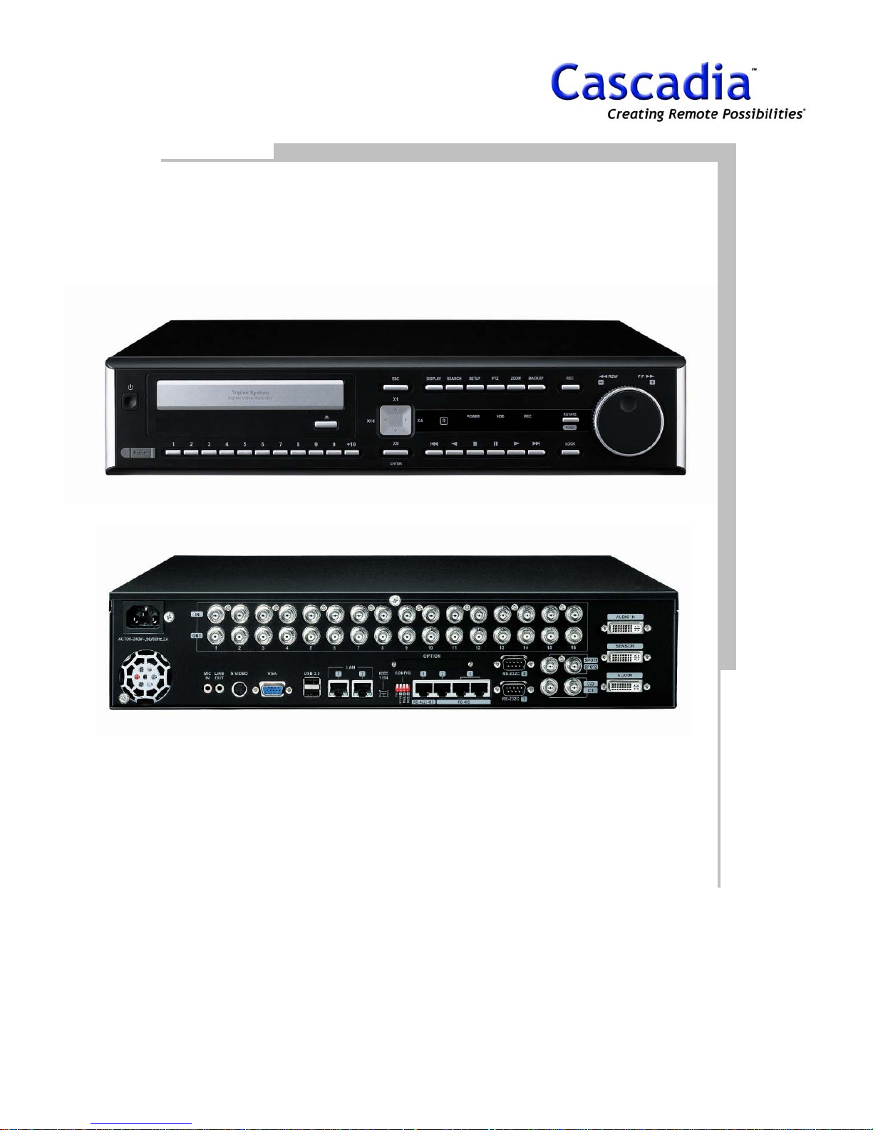
1. LAYOUT
FRONT VIEW
www.cascadiadvrt.com / (888) 421-0050
REAR VIEW
6
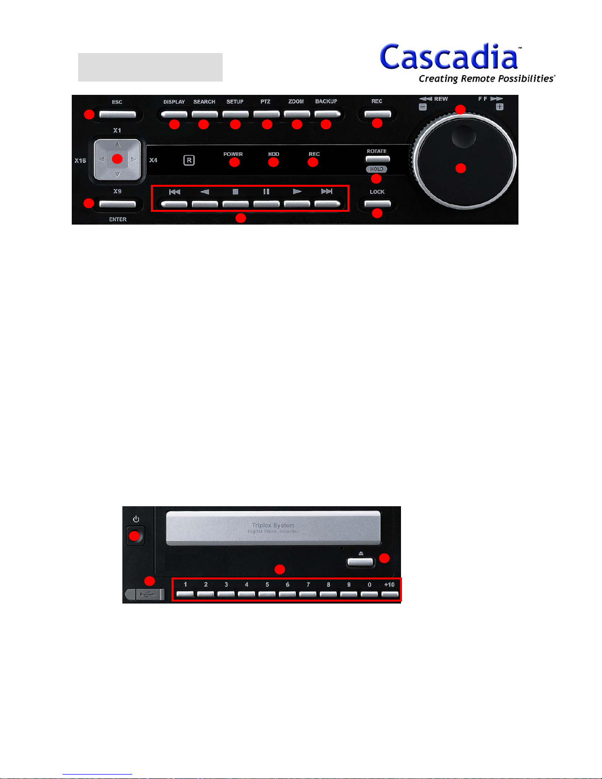
FRONT VIEW
15
13
14
1 2 3 4 5 6
16 17 18
10
1. Display Button
Shows the Display menu.
2. Search Button
Go to the Search menu.
3. Setup Button
Go to the Setup menu.
4. PTZ Button
Pan / tilt a selected camera.
5. Zoom Button
Zoom In/Out at 1CH Layout mode.
6. Backup Button
Go to the Backup menu.
7. REC Button
Record all cameras manually for emergency.
8. Rotate / Hold Button
Rotates the Live Camera Display.
Hold the search speed with Jog & Shuttle.
9. Lock Button
Locks the DVR.
10. Playback Button
Play, Pause, Reverse, Stop, End, Start.
12
7
11
8
9
11. Jog Dial
Play recorded images frame by frame when this
dial is rotated.
12. Shuttle Ring
Play fast when this dial is rotated.
13. Direction / Camera Layout Button
Move the cursor on the menu and shows camera
Layout.
UP: 1CH Layout,
Right: 4CH Layout
Down: 9CH Layout
Left: 16CH Layout
14. Enter Button
Determine the setting values.
15. ESC Button
Go back to the previous status.
16. Power LED
Light up when power is on.
17. HDD LED
Light up when built-in HDD is working.
18. REC LED
Light up when Manual recording is on.
19
20
19. Power Button
20. USB Port
Plug USB memory stick Upgrade
Software or Save Data. (USB 2.0)
www.cascadiadvrt.com / (888) 421-0050
22
21
21. Camera Button
Choose a camera you want to see.
22. CD/DVD Eject Button
7
REAR VIEW
Rear View
1. Camera Input Connectors
Connect cameras to these BNC connectors.
2. Camera Output Connectors (Loop Out)
These BNC connectors supply video signals looped
through the video input connectors.
3. Mic In
Connect a microphone to communication between DVR
and Client S/W.
4. Line Out
Connect a speaker for audio out.
5. S-Video
Connect a monitor to S-VHS connector.
6. VGA
Connect a VGA monitor with this connector.
7. USB (2.0)
Connect USB memory stick for Upgrade and for external
device like CD/DVD and other devices.
8. LAN (10/100BASE-T)
Connect this unit to a network compatible with
10BASET or 100BASE-Tx.
9. IEEE1394
Connect to an external device like CD/DVD RW.
10. CONFIG (UP-OFF, DOWN –ON)
1. NTSC(OFF)/PAL(ON)
2. ① – 485(OFF)/422(ON)
3. ② – 120ohm Termination (ON)
4. ③ – 120ohm Termination (ON)
11. RS422/485
Connect a keyboard or PTZ.
12. ② RS-485
Connect a device using RS485 connector. Support
120 ohm termination.
Refer to No. 10, CONFIG setting.
13. ③ RS-485 (Cascade In/Out)
Connect with the cascade Out connector of another
DVR for communication.
14. RS232C
Connect a device that support RS232C like PTZ or
POS.
15. Spot 1
Show quad out on an analogue monitor.
(Fixed, Rotation) (1X1, 2X2)
16. Spot 2
Show quad out on analogue monitor.
(Fixed, Rotation) (1X1, 2X2, 3X3, 4X4)
17. Cascade In/Out (BNC)
Connect with the CASCADE IN/OUT connector of
another DVR for image transmission.
18. Audio Input Connectors (AUDIO IN 1 - 4)
Input audio signal supplied from an external device
such as a microphone amplifier.
19. SENSOR (ALARM IN)
Connect an external device such as a sensor or a
door switch.
20. Alarm Out
Connect a control switch when controlling this unit
using an external device, or when controlling an
alarm device such as a buzzer or a lamp.
www.cascadiadvrt.com / (888) 421-0050
8
2. DISPLAY
www.cascadiadvrt.com / (888) 421-0050
9
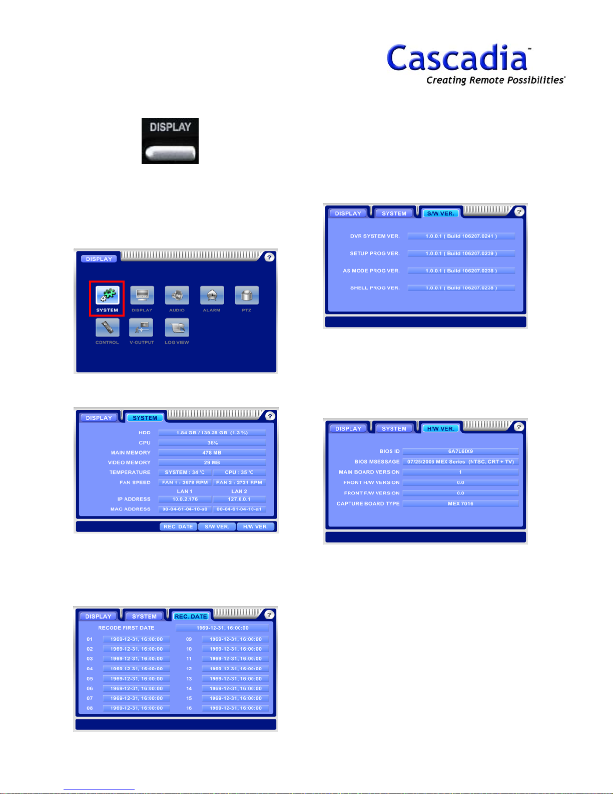
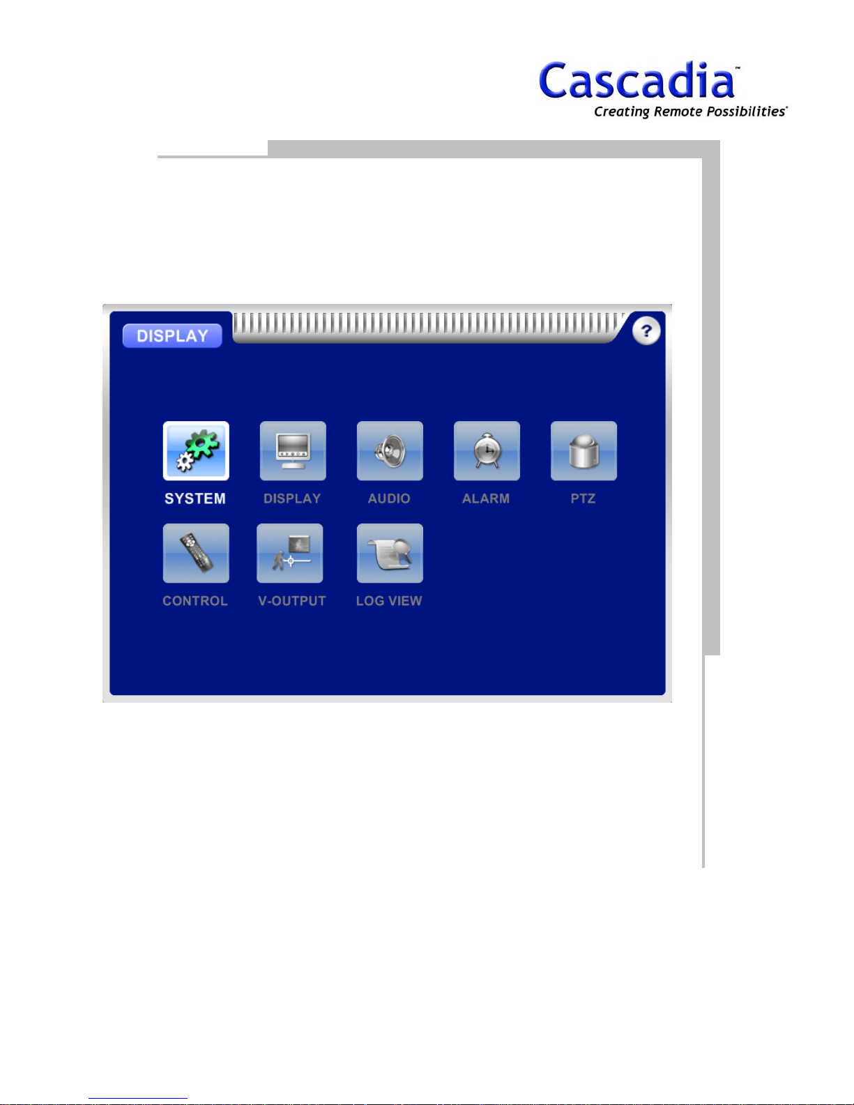
DISPLAY / SYSTEM MENU
1. Press “DISPLAY”
The DISPLAY MENU will be displayed. Move the
curser to h
the “Enter” button to show the system
information.
2. DISPLAY / SYSTEM
ighlight the “SYSTEM” Icon and press
4. DISPLAY / SYSTEM / S/W VER.
Move the curser to highlight the “S/W VER.”
Icon and press the “Enter” button to display
S/W version.
the
5. DISPLAY / SYSTEM / H/W VER.
Move the curser to highlight the “H/W VER.”
Icon and press the “Enter” button to display the
H/W version.
3. DISPLAY / SYSTEM / REC.DATE
Move the curser to highlight the “REC. DATE”
Icon and press the “Enter” button to show
oldest recorded date on each camera.
www.cascadiadvrt.com / (888) 421-0050
the
10

DISPLAY / DISPLAY MENU
1. Press “DISPLAY”
The DISPLAY MENU will be displayed. Move the
curser to highlight the “DISPLAY” Icon and
press the “Enter” button to show the display
information.
2. DISPLAY / DISPLAY
Rotation: Camera split rotation.
Event Popup: Pop up on motion, sensor &
POS.
Status: Show the information bar on live mode.
3. DISPLAY / DISPLAY / LAYOUT
Layout: Default camera screen division layout
Width Margin: status bar margin width
Height Margin: status bar margin height
4. DISPLAY / DISPLAY / POS
Live Mode Display: Shows the POS information
on live mode (On/Off).
Popup Display: Pops up the POS information
with a camera (On/Off).
Display Duration: Sets the pop up duration time
of the POS information (seconds).
www.cascadiadvrt.com / (888) 421-0050
11
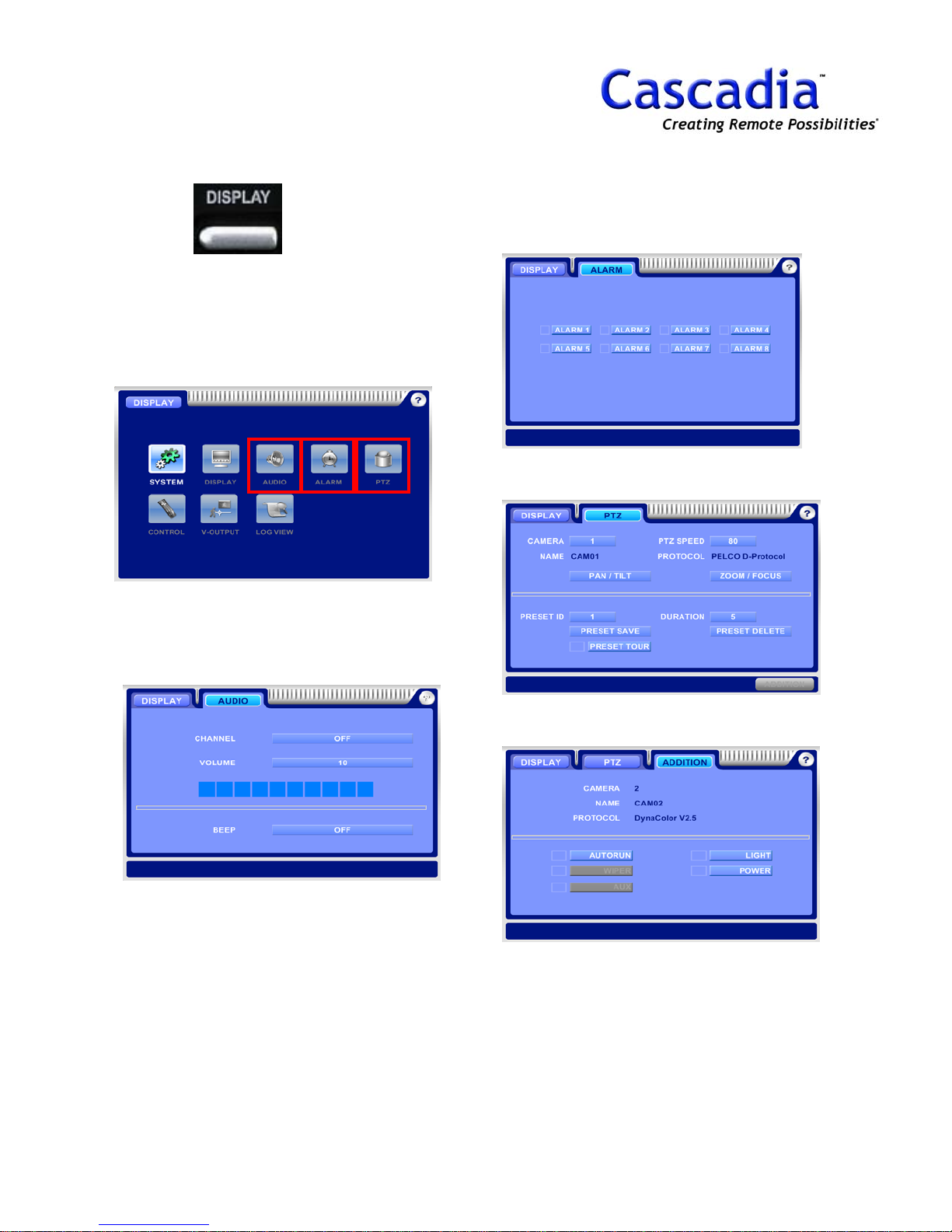
DISPLAY / AUDIO, ALARM,
PTZ MENU
1. Press “DISPLAY”
The DISPLAY MENU will be displayed. Move the
curser to highlight the “AUDIO” Icon, “ALARM”
Icon or “PTZ” Icon and press the “Enter” button
to show the appropriate information.
4. DISPLAY / PTZ
Control a PTZ camera.
3. DISPLAY / ALARM
Alarm On/Off.
2. DISPLAY / AUDIO
Channel: Select an audio CH No.
Beep: Beep On/Off on system warning.
5. DISPLAY / PTZ / ADDITION
Show an additional PTZ camera menu.
www.cascadiadvrt.com / (888) 421-0050
12
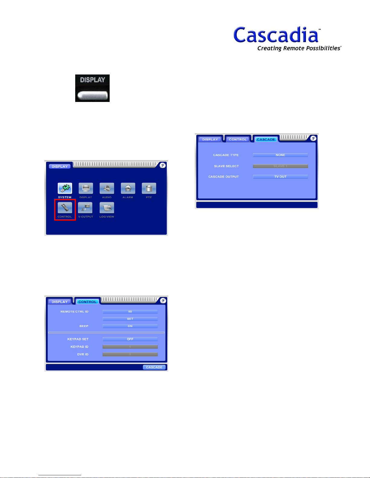
DISPLAY / CONTROL MENU
1. Press “DISPLAY”
The DISPLAY MENU will be displayed. Move the
curser to highlight the “CONTROL” Icon and
press the “Enter” button to show the control
information.
3. DISPLAY / CONTROL / CASCADE
Cascade Type: Set a DVR to Master or Slave.
Slave Select: Select a slave DVR No. to show
on monitor.
Cascade Output: Select an output to show on
cascade output.
2. DISPLAY / CONTROL
Remote CTRL ID: Remote controller ID.
Beep: Remote controller Beep On/Off.
Keypad Set: Keypad use On/Off
Keypad ID: Set a keypad ID.
DVR ID: Set a DVR ID.
www.cascadiadvrt.com / (888) 421-0050
13

DISPLAY / V-OUTPUT,
LOG VIEW MENU
1. Press “DISPLAY”
The DISPLAY MENU will be displayed. Move the
curser to highlight the “V-OUTPUT” Icon or
“LOG VIEW” Icon and press the “Enter” button
to show the appropriate information.
NOTE:
Spot1 = Support 1X1,2X2 layout.
Spot2 = Support 1X1, 2X2, 3X3, 4X4 layout.
3. DISPLAY / LOG VIEW
Show the log information of DVR.
2. DISPLAY / V-OUTPUT
Mode: Select a fixed and rotation mode for
spot.
Camera: Select a camera layout.
www.cascadiadvrt.com / (888) 421-0050
14

3. SETUP
CAMERA
RECORD
SCHEDULE
MOTION
SENSOR
ALARM
NETWORK
STORAGE
USER
POS
www.cascadiadvrt.com / (888) 421-0050
15
SYSTEM
EVENT
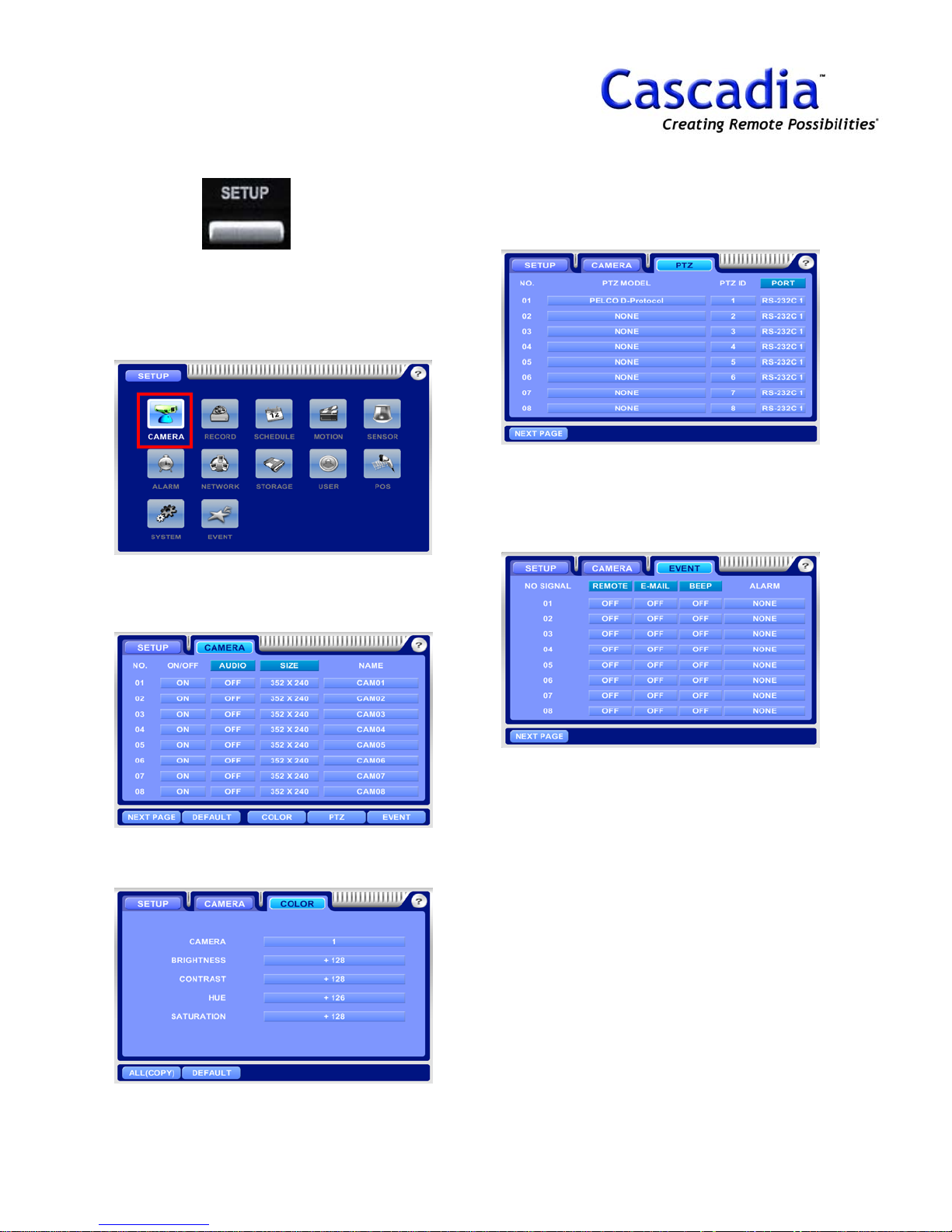
SETUP / CAMERA MENU
1. Press” SETUP”
The SETUP MENU will be displayed. Move the
curser to highlight the “CAMERA” Icon and
press the “Enter” button to show the camera
information.
2. SETUP / CAMERA
On/Off: Camera On/Off.
Audio: Audio = On/Off, Size = Resolution.
4. SETUP / CAMERA / PTZ
Set a camera protocol, ID and Port.
5. SETUP / CAMERA / EVENT
Set a remote transmission, e-mail and beep on
no video signal.
3. SETUP / CAMERA / COLOR
Set a color of camera.
www.cascadiadvrt.com / (888) 421-0050
NOTE:
Item selection: Move the cursor using the
arrow buttons.
Change the setting: Press “Enter” button.
NOTE:
Default P/W is “0”.
16
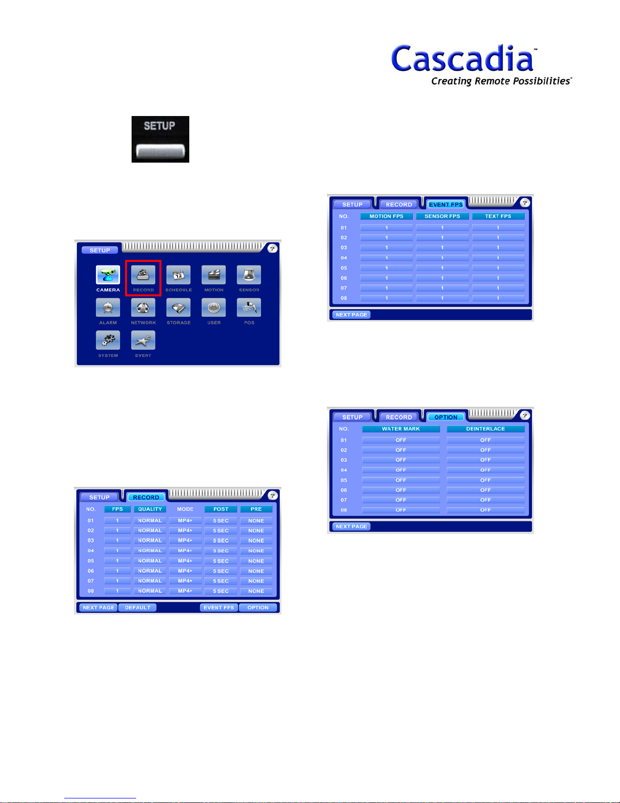
SETUP / RECORD MENU
1. Press “SETUP”
The SETUP MENU will be displayed. Move the
curser to highlight the “RECORD” Icon and
press the “Enter” button to show the record
information.
2. SETUP / RECORD
Fps = Recording speed
Quality = Image Quality
Mode = Compression
(MP4+ = Network Priority, MP4 = Image size
Priority)
Post & Pre = Post & Pre recording
3. SETUP / RECORD / EVENT FPS
Motion FPS = Recording speed of Motion.
Sensor FPS = Recording speed of Sensor.
Text FPS = Recording speed of POS.
4. SETUP / RECORD / OPTION
Watermark = Watermarking recording data per
camera.
Deinterlace = Anti aliasing filter.
www.cascadiadvrt.com / (888) 421-0050
NOTE:
Item selection: Move the cursor using the
arrow buttons.
Change the setting: Press “Enter” button.
NOTE:
Default P/W is “0”.
17
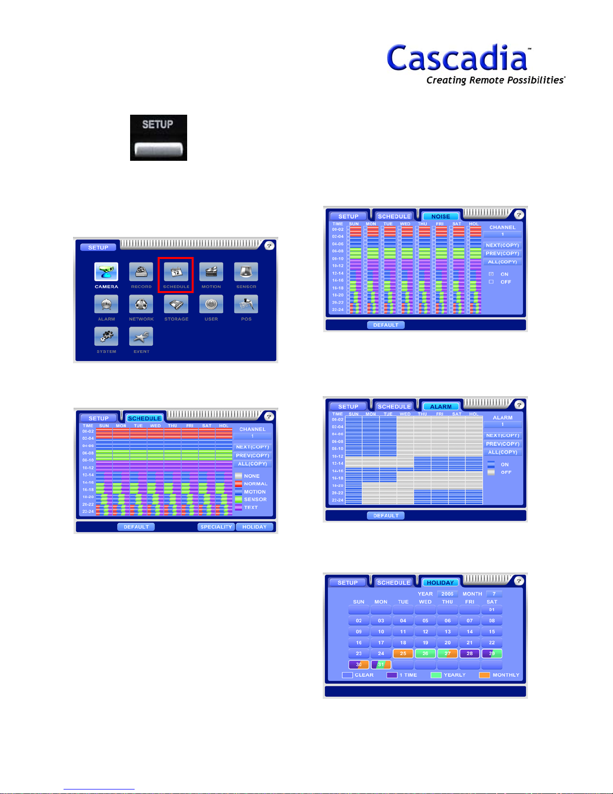
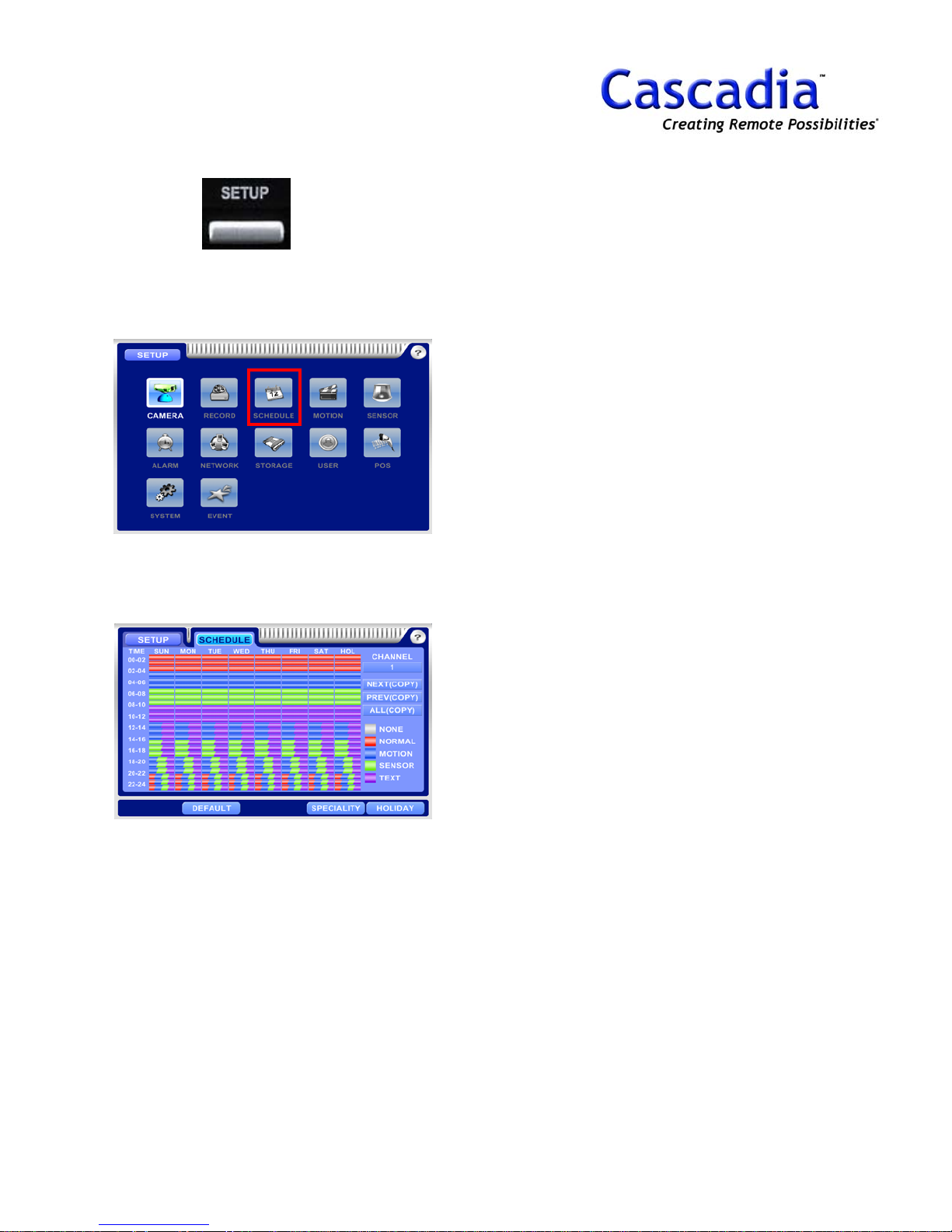
SETUP - SCHEDULE MENU
1. Press “SETUP”
The SETUP MENU will be displayed. Move the
curser to highlight the “SCHEDULE” Icon and
press the “Enter” button to show the schedule
information.
2. SETUP / SCHEDULE
Set a schedule for each camera.
3. SETUP / SCHEDULE / SPECIALITY /
NOISE
Recording speed will be changed when noise
schedule is set.
It’s effective to save HDD capacity for night
time.
4. SETUP / SCHEDULE / SPECIALITY /
ALARM
Set an alarm schedule for each alarm.
Alarm goes off when alarm schedule is set.
www.cascadiadvrt.com / (888) 421-0050
5. SETUP / SCHEDULE / HOLIDAY
Set a schedule for holiday.
18

SETUP / MOTION, SENSOR
MENU
1. Press “SETUP”
The SETUP MENU will be displayed. Move the
curser to highlight the “MOTION” or
“SCHEDULE” Icon and press the “Enter” button
to show the appropriate information.
2. SETUP / MOTION
Set a motion area and sensitivity.
4. SETUP / SENSOR
Type: Sensor type (N/C, N/O).
Camera: Select a linked camera for each
sensor.
5. SETUP / SENSOR / EVENT
Set a remote transmission, e-mail, beep and
alarm on sensor.
3. SETUP / MOTION / EVENT
Set a remote transmission, e-mail, beep and
alarm on motion.
www.cascadiadvrt.com / (888) 421-0050
NOTE:
Item selection: Move the cursor using the arrow
buttons.
Change the setting: Press “Enter” button.
NOTE:
Default P/W is “0”.
19
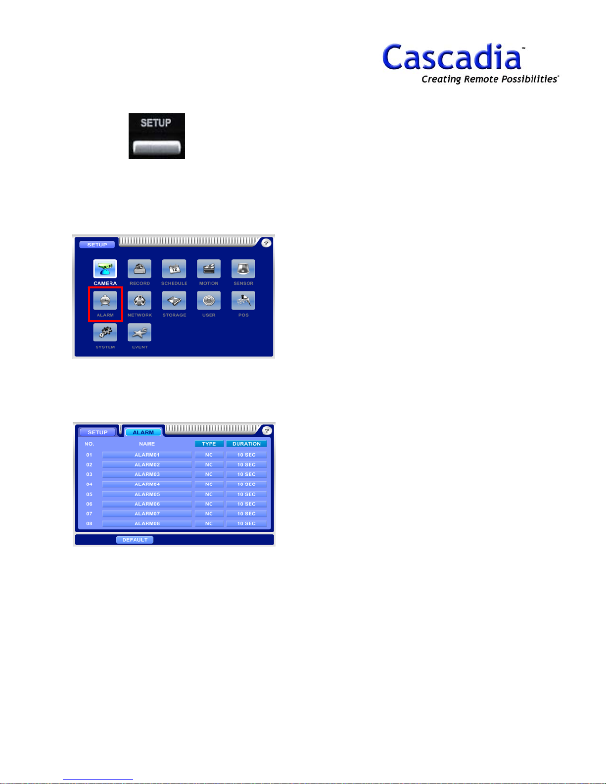
SETUP / ALARM MENU
1. Press “SETUP”
The SETUP MENU will be displayed. Move the
curser to highlight the “ALARM” Icon and press
the “Enter” button to show the alarm
information.
2. SETUP / ALARM
Type: Alarm type (N/C, N/O).
Duration: Set an alarm duration.
NOTE:
Item selection: Move the cursor using the arrow
buttons.
Change the setting: Press “Enter” button.
NOTE:
Default P/W is “0”.
www.cascadiadvrt.com / (888) 421-0050
20
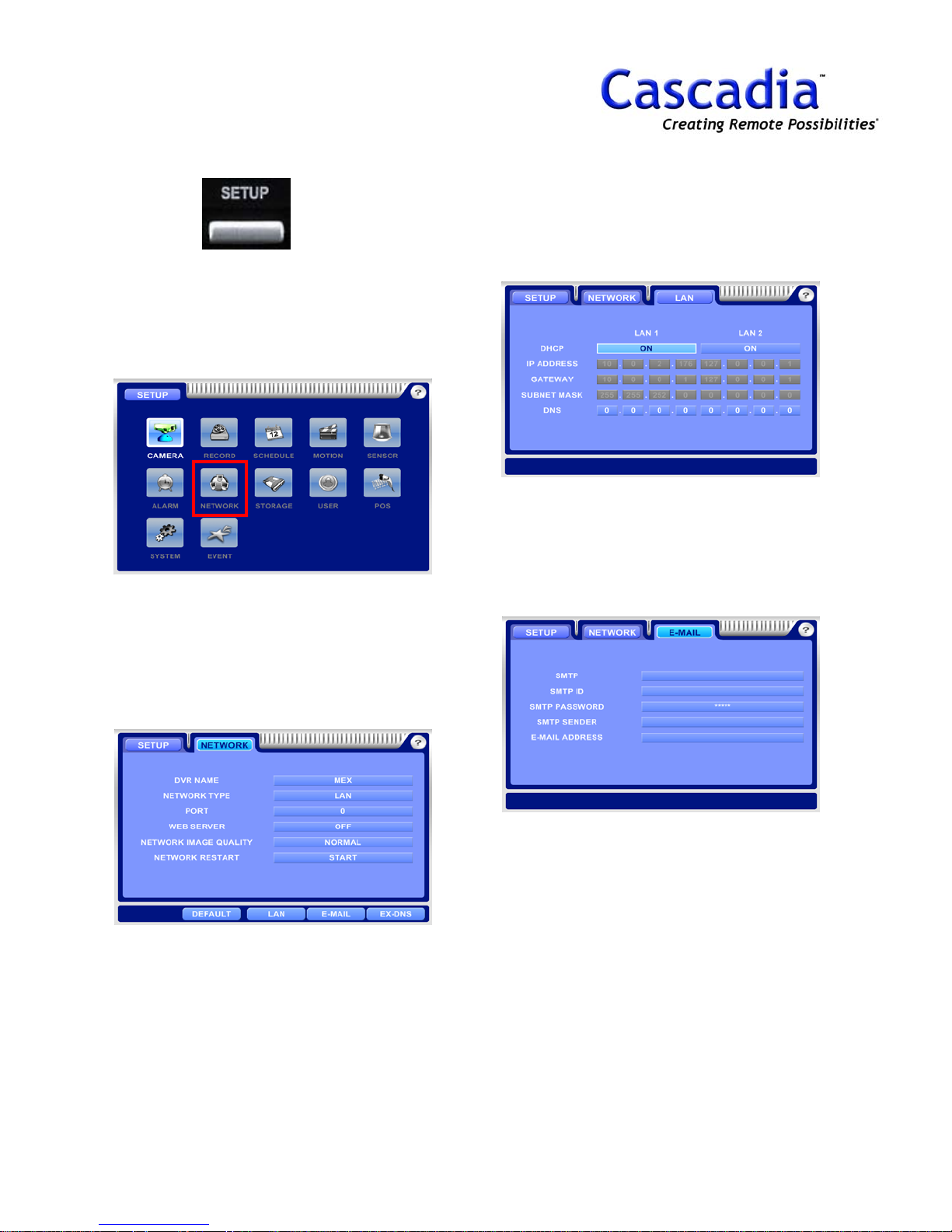
SETUP / NETWORK MENU
1. Press “SETUP”
The SETUP MENU will be displayed. Move the
curser to highlight the “NETWORK” Icon and
press the “Enter” button to show the network
information.
3. SETUP / NETWORK / LAN
It has two LAN. (LAN1, LAN2)
One will be used for future use like NAS.
The other is for normal network connection.
4. SETUP / NETWORK / E-MAIL
SMTP: Input a Mail Server IP.
SMTP ID: Input a SMTP ID.
SMTP P/W: Input a SMTP P/W.
SMTP Sender: Input a sender’s mail address.
2. SETUP / NETWORK
DVR Name: Type an DVR name.
Network Type: Select a network type.
Web Server: Web Viewer On/Off.
Network Image Quality: Image quality for
network transmission.
NOTE:
Item selection: Move the cursor using the arrow
buttons.
Change the setting: Press “Enter” button.
NOTE:
Default P/W is “0”.
www.cascadiadvrt.com / (888) 421-0050
21
SETUP / NETWORK MENU
(cont.)
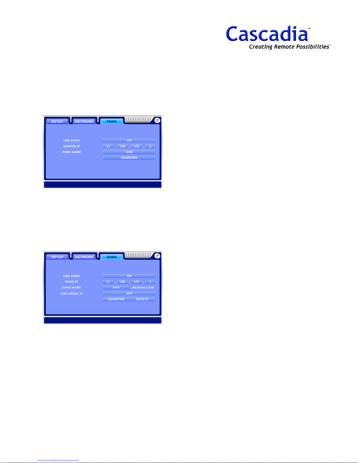
4. SETUP / NETWORK / EX DNS / PDNS
Support a Dynamic IP address with Client connection
S/W.
PDNS Name: Type a DVR name for PDNS server
recognition.
Register: Register a DVR ID on PDNS server.
5. SETUP / NETWORK / EX DNS / DDNS
Support a Dynamic IP address with internet explorer.
DDNS Name: Type a DVR name for DDNS server
recognition.
Use Local IP: Set “ON” to use DDNS only in LAN.
Register: Register a DDNS name on DDNS server.
NOTE:
Item selection: Move the cursor using the
arrow buttons.
Change the setting: Press “Enter” button.
NOTE:
Default P/W is “0”.
www.cascadiadvrt.com / (888) 421-0050
22
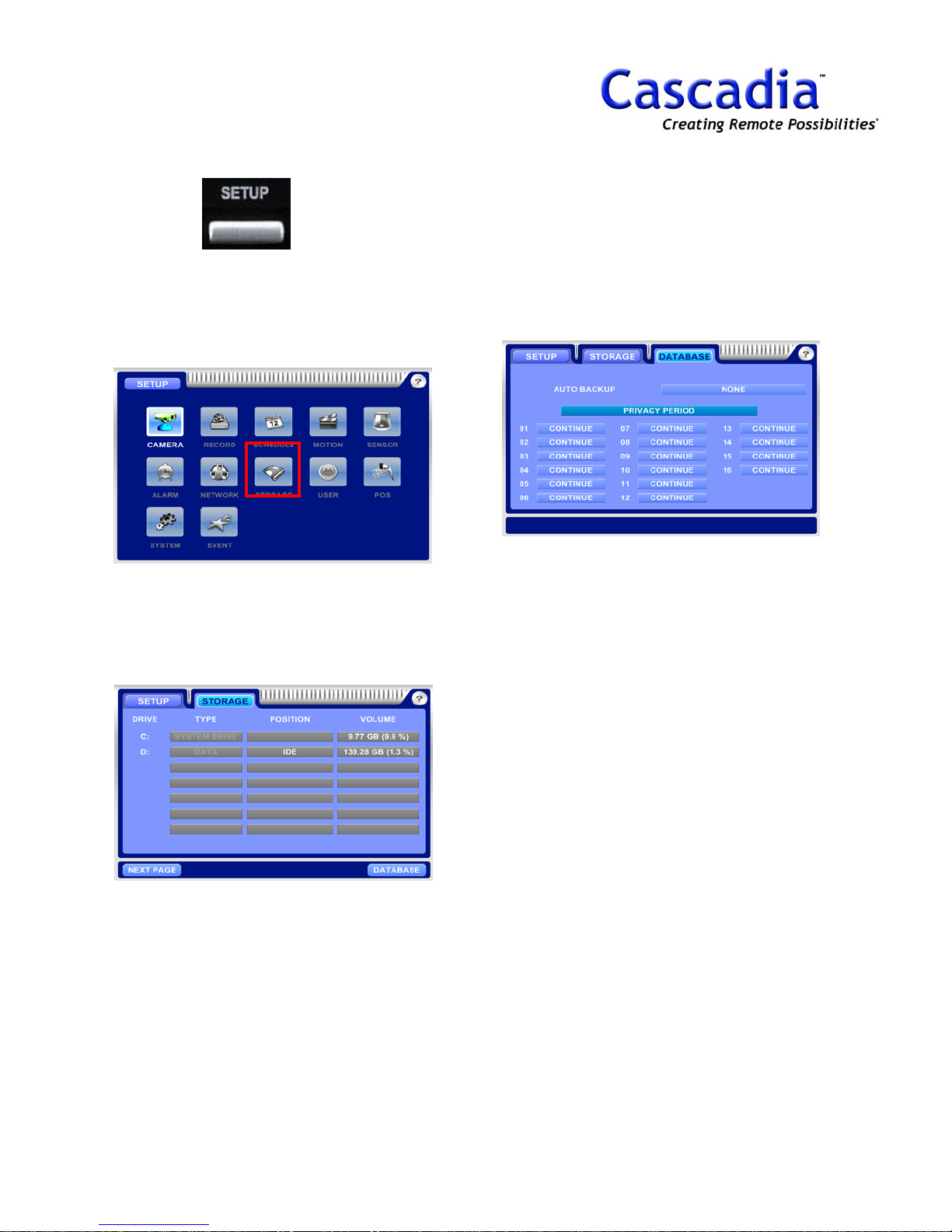
SETUP / STORAGE MENU
1. Press “SETUP”
The SETUP MENU will be displayed. Move the
curser to highlight the “STORAGE” Icon and
press the “Enter” button to show the storage
information.
2. SETUP / STORAGE
Type: Select a HDD as Data, Backup, Auto
Backup and Mirroring.
Position: Show a device type like IDE, IEEE etc.
Volume: Capacity.
3. SETUP / STORAGE / DATABASE
Privacy Period: Set a data keeping time on DVR.
Auto Backup: Select a camera No. for auto backup.
NOTE:
Item selection: Move the cursor using the
arrow buttons.
Change the setting: Press “Enter” button.
NOTE:
Default P/W is “0”.
www.cascadiadvrt.com / (888) 421-0050
23
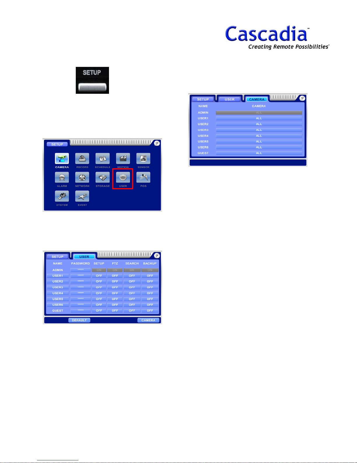
SETUP / USER MENU
1. Press “SETUP”
The SETUP MENU will be displayed. Move the
curser to highlight the “USER” Icon and press
the “Enter” button to show the user information.
3. SETUP / USER / CAMERA
Set a camera use for each user.
NOTE:
Item selection: Move the cursor using the arrow
buttons.
Change the setting: Press “Enter” button.
2. SETUP / USER
Set a user authority like P/W, Setup, PTZ,
Search and Backup.
NOTE:
Default P/W is “0”.
www.cascadiadvrt.com / (888) 421-0050
24

SETUP / POS MENU
1. Press “SETUP”
The SETUP MENU will be displayed. Move the
curser to highlight the “POS” Icon and press
the “Enter” button to show the POS information.
2. SETUP / POS
Set a POS configuration.
4. SETUP / POS / MULTI BOX
Set a POS configuration.
NOTE:
Please contact to the local distributor for
more information of POS Setting.
NOTE:
Item selection: Move the cursor using the
arrow buttons.
Change the setting: Press “Enter” button.
3. SETUP / POS / EVENT
Set a POS with alarm device, beep, remote and
e-mail transmission.
www.cascadiadvrt.com / (888) 421-0050
NOTE:
Default P/W is “0”.
25

SETUP / SYSTEM MENU
1. Press “SETUP”
The SETUP MENU will be displayed. Move the
curser to highlight the “SYSTEM” Icon and
press the “Enter” button to show the system
information.
2. SETUP / SYSTEM
Import/Export = Load/Save a configuration file.
4. SETUP / SYSTEM / LOCAL / TIME
Set a time sync server.
5. SETUP / SYSTEM / LOCAL / LANG
Set a language, date/time format.
3. SETUP / SYSTEM / EVENT
Set a remote transmission, e-mail, beep and
alarm for FAN, temperature, HDD, time sync.
www.cascadiadvrt.com / (888) 421-0050
26

SETUP - EVENT MENU
1. Press “SETUP”
The SETUP MENU will be displayed. Move the
curser to highlight the “EVENT” Icon and press
the “Enter” button to show the event
information.
2. SETUP / EVENT
Import/Export = Load/Save a configuration file.
4. SETUP / EVENT / MOTION
Set a remote transmission, e-mail, beep and
alarm for motion.
5. SETUP / EVENT / SENSOR
Set a remote transmission, e-mail, beep and
alarm for sensor.
3. SETUP / EVENT / NO VIDEO SIGNAL
Set a remote transmission, e-mail, beep and
alarm for no video signal.
www.cascadiadvrt.com / (888) 421-0050
6. SETUP / EVENT / SYSTEM
Set a remote transmission, e-mail, beep and
alarm for system warning.
27

4. A/S SETUP
TIME
UPGRADE
DISK
ETC
CHECK
www.cascadiadvrt.com / (888) 421-0050
28

SETUP / SYSTEM / A/S
MENU
1. Go to SETUP / SYSTEM / A/S
A/S MENU will be displayed. (See previous page
for the two step process to get to the A/S
Mode).
2. SETUP / SYSTEM / A/S / TIME
Set a local time zone and time.
4. SETUP / SYSTEM / A/S / DISK
Format the HDD.
5. SETUP / SYSTEM / A/S / ETC.
Set a logo, video signal type, TV output.
3. SETUP / SYSTEM / A/S / UPGRADE
Support a USB memory stick for upgrade.
www.cascadiadvrt.com / (888) 421-0050
6. SETUP / SYSTEM / A/S / CHECK
Sensor and alarm self-test.
29

5. SEARCH
CALENDAR
VIDEO MAP
EXPORT IMG
EXPORT AVI
SMART
TEXT
www.cascadiadvrt.com / (888) 421-0050
30

SEARCH / CALENDAR,
VIDEO MAP
1. Press SEARCH button
The CALENDAR will be displayed.
Date with recorded data will be marked in BLUE.
NOTE:
How to move the time indicator.
Use the arrow buttons and jog dial.
How to change the screen layout.
Press Direction buttons of1-4-9-16 CH screen layout.
2. Select “Hour” and press “Enter” button.
Hour map will show up. (24 hours data)
3. Select “Minute” and press “Enter”
button.
Minute map will show up. (1 hour data)
www.cascadiadvrt.com / (888) 421-0050
31

SEARCH / EXPORT IMG,
AVI, SMART
1. Press “SEARCH” button while in
Search Mode.
The Search menu will be displayed. Move the
curser to highlight the “IMAGE”, “AVI” or
“IMAGE” Icon and press the “Enter” button to
use the appropriate tools.
4. SEARCH / SMART
Detect a movement when motion is detected
in the specific area.
5. SEARCH / TEXT
Search a text in POS.
2. SEARCH / IMAGE
Save a data as JPG, BMP file format.
3. SEARCH / AVI
Save a data as AVI file format.
NOTE:
How to move the time indicator.
Use the arrow buttons and jog dial.
How to change the screen layout.
Press Direction buttons of 1-4-9-16 CH screen
layout.
www.cascadiadvrt.com / (888) 421-0050
32

6. QUICK USE
1
TIME & DATE ADJUSTMENT
DVR & REMOTE CONTROLLER ID
SETUP
HOW TO UPGRADE
www.cascadiadvrt.com / (888) 421-0050
33

TIME / DATE
ADJUSTMENT
1. Press “SETUP”
2. Select “SYSTEM” menu.
4. Select “TIME” menu.
TIME menu will be displayed.
5. Select “Time Zone” first and set the
date and time.
6. Select “Apply” to save.
7. Select “ESC” button to exit.
3. Select “A/S Mode” menu.
A/S MENU will be displayed.
www.cascadiadvrt.com / (888) 421-0050
34

DVR / REMOTE
CONTROLLER ID SETUP
ID Setting of DVR
Set a remote controller ID as described below.
1. Press “Display”
The DISPLAY MENU will be displayed.
2. Select “CONTROL” menu.
Set a remote CTRL ID.
ID Setting of Remote Controller
Set a remote controller ID as described below.
1. Face controller to IR receiver of
DVR.
2. Holding the “ID” button of the
remote
Power LED will twinkle.
3. Press No. of Remocon ID you set on
DVR.
controller.
3. Press “ESC” button to save and exit.
www.cascadiadvrt.com / (888) 421-0050
4. Press “Enter” button.
Power LED will stop twinkle.
NOTE:
When CTRL ID of DVR matches the remote
controller ID, the LED on the front of the
POWER stops twinkling.
35

HOW TO UPGRADE
1. Press “SETUP”
4. Plug in USB memory stick with
UPGRADE file to DVR.
5. Select “UPGRADE” menu.
UPGRADE menu will be displayed.
2. Select “SYSTEM” menu.
3. Select “A/S Mode” menu.
A/S MENU will be displayed.
6. Select “START”.
7. Upgrade process will be started.
NOTE:
DVR will restart after finishing upgrade process.
www.cascadiadvrt.com / (888) 421-0050
36

7. QUICK USE
2
MANUAL RECORDING
SCHEDULE RECORDING
www.cascadiadvrt.com / (888) 421-0050
37

MANUAL RECORDING
1. Start “Manual Recording”.
Press the REC button to start manual recording.
The indicator of REC will light and recording will
start.
Images from all the connected cameras will be
recorded manually with the current recording
rate.
NOTE:
When manual recording is performed, schedule
recording will not be performed until force
recording stops.
2. Stop “Manual Recording”.
Press the REC button again to stop recording.
The indicator on the button will go off and
recording will stop.
Images from all the connected cameras will be
recorded with the scheduled recording rate as
schedule.
www.cascadiadvrt.com / (888) 421-0050
38
SCHEDULE RECORDING
8. Select the recording status.
The below recording mode will be shown.
(NONE, NORMAL, MOTION, SENSOR, TEXT)
1. Press “SETUP”
The SETUP MENU will be displayed.
2. Select “SCHEDULE” menu.
The SCHEDULE menu will be displayed.
9. Press “ESC” button to exit.
NOTE:
The below is the example of setting the time
schedule.
EX) Normal + Motion Recording, 09:00 to
18:00, Sunday to Saturday for Cam No. 2.
1. Select CH No. 2
2. Move the 09:00 of Sunday.
3. Press “ENTER” button.
4. Move the cursor to 18:00 of Saturday.
5. Press “Enter” button.
(Recording status menu will show up.)
6. Select “Normal” and “Motion”.
7. Press “ESC” button
3. Select “CHANNEL”.
4. Move the cursor to the start time.
5. Press “ENTER” button.
6. Move the cursor to the end time.
7. Press “ENTER” button again to set
the recording status.
www.cascadiadvrt.com / (888) 421-0050
39

8. QUICK USE
3
NORMAL SEARCH
SMART SEARCH
TEXT SEARCH
www.cascadiadvrt.com / (888) 421-0050
40

NORMAL SEARCH
1. Press “SEARCH”
Date with recorded data will be marked in
.
BLUE
2. Select the date.
Hour map will be displayed for 24 hours.
4. Playback mode will show up.
NOTE:
How to move the time indicator.
Use the arrow buttons and jog dial.
How to change the screen layout.
Press Direction buttons of 1-4-9-16 CH screen
layout.
3. Select the time.
Minute map will be displayed for 1 hour.
www.cascadiadvrt.com / (888) 421-0050
41

SMART SEARCH
1. Press “SEARCH” button in playback
Mode.
The Search menu will be displayed.
2. Select “SMART” menu.
The SMART menu will be displayed.
3. Select the camera No.
4. Select the sensitivity level.
5. Select the region for smart search.
NONE, AREA, FULL are selectable.
6. Select “Slow Play” or “Fast Play”.
f motion is detected in the selected area, it will
stop searching and show the detected image.
www.cascadiadvrt.com / (888) 421-0050
42

TEXT SEARCH
1. Press “SEARCH” button in playback
Mode.
The Search menu will be displayed.
NOTE:
TEXT search will be available with POS.
2. Select “TEXT” menu.
The TEXT menu will be displayed.
3. Select the camera No.
4. Select the date & time.
5. Select the device ID, POS.
6. Select the event.
7. Select the keyword for search.
8. Select “Search”.
www.cascadiadvrt.com / (888) 421-0050
43

9. QUICK USE
4
STILL IMAGE SAVE
BACKUP
www.cascadiadvrt.com / (888) 421-0050
44

JPG, BMP, AVI SAVE
1. Press “SEARCH” button in playback
Mode.
The Search menu will be displayed.
1. Press “SEARCH” button in playback
Mode.
The Search menu will be displayed.
2. Select “AVI” m enu.
The AVI menu will be displayed.
2. Select “IMAGE” menu.
The IMAGE menu will be displayed.
3. Select “Device”.
4. Select “Camera”.
5. Select “Chain Image”.
Select the image no. for save.
6. Select “Format”.
Select the file format like JPG, BMP.
3. Select “Device”.
4. Select “Camera”.
5. Select “Audio”.
Select the audio save with AVI.
6. Select “Duration”.
Select the AVI saving time.
7. Select “START”.
7. Select “START”.
www.cascadiadvrt.com / (888) 421-0050
45

BACKUP
To copy recorded images to the CD-RW or DVD
disk, formatting (initializing) the disk is required in
advance.
1. Press “Backup”
The BACKUP MENU will be displayed.
6. Press “START” button
Show a backup progressing window.
2. Select a backup device.
Select a Backup device like CD-RW, DVD.
3. Move the cursor to “ERASE” for
Format and Press “Enter” button.
During formatting, the status window will be
displayed. The status window will be cl osed
automatically when completing formatting.
NOTE:
All data on the disk will be deleted if formatted
(initialized).
It is impossible to recover the deleted images
on CD/DVD media.
4. Select a camera for backup.
5. Set “Start” & “End” time.
Selected data size will be shown.
www.cascadiadvrt.com / (888) 421-0050
46

10. QUICK USE
5
IP SETTING / CONNECTING
DDNS / WEB VIEWER CONNECTING
PDNS CONNECTING
E-MAIL SETTING & NOTIFICATION
USER P/W SETTING
www.cascadiadvrt.com / (888) 421-0050
47
IP SETTING / CONNECTING
4. Set “DHCP” to “ON” or “OFF”.
Input the IP address, subnet mask, gateway
when DHCP is OFF.
1. Press “SETUP”
The SETUP MENU will be displayed.
2. Select “NETWORK” menu.
Select the network type and network image
quality. LAN (TCP/IP)
NOTE:
Please ask your network manager when you
are not sure of DHCP or IP address.
CONNECTION WITH “IP” ADDRESS.
1. Run “DVR Client” S/W.
2. Click “Search” button.
3. Click “New Address” button.
3. Select “LAN”.
Please select LAN1. (LAN2 is for future use.)
www.cascadiadvrt.com / (888) 421-0050
48

IP SETTING / CONNECTING
(cont.)
4. Input “IP Address”.
NOTE:
If user has a network system with firewall,
please ask your network manager the Port No.
to communicate with DVR.
www.cascadiadvrt.com / (888) 421-0050
49
DDNS / WEB VIEWER
CONNECTING
4. Set “USE DDNS” to “ON”.
5. Type “ DDNS Name” .
1. Press “SETUP”
The SETUP MENU will be displayed.
2. Select “NETWORK” menu.
Select “Network Type”.
Select “Network Image Quality”.
Set “Web Viewer” to “ON”.
6. Select “Register” to register DDNS
Name on DDNS Server.
NOTE:
Set “Use Local IP” to “ON” when uses DDNS in
local network like LAN.
How to register DDNS Name on DDNS
server.
1. Enable “DDNS USE” to “ON”
2. Type the DDNS Name.
3. Press “REGISTER” to register the domain
name on DDNS Server.
How to use web viewer with Internet
Explorer.
1. Run “Internet Explorer”.
2. Type the registered domain name of DDNS.
Refer to the below example figure.
3. Select “User ID” and Input “P/W”.
4. Click “Connect” button.
3. Select “EX DNS” / “DDNS”
www.cascadiadvrt.com / (888) 421-0050
http://dvr.mexdvr.com
If the registered DDNS name is “dvr”, please
type like the below example.
Ex) http://dvr.pxedvr.com
50

PDNS CONNECTING
4. Set “USE PDNS” to “ON”.
5. Type “ PDNS Name”.
1. Press “SETUP”
The SETUP MENU will be displayed.
2. Select “NETWORK” menu.
Select “Network Type”.
Set “Network Image Quality”.
6. Select “Register” to register PDNS
name on PDNS Server.
How to register a PDNS Name on
PDNS
server.
1. Enable “USE PDNS” to “ON”
2. Type the PDNS name.
3. Press “REGISTER” to register the domain
name on PDNS Server.
CONNECTION WITH with “PDNS”.
1. Run “DVR Client” S/W.
2. Click “Search” button.
3. Select “EX DNS” / “PDNS”
www.cascadiadvrt.com / (888) 421-0050
3. Click “New Address” button.
51

PDNS CONNECTING
(cont.)
4. Input the DVR ID into the “Server Name”.
NOTE:
If user registered DVR ID as “DVR” into the
PDNS Server, please type like the below.
Ex) @dvr
5. Click “OK” button.
www.cascadiadvrt.com / (888) 421-0050
52

E-MAIL SETTING /
NOTIFICATION
1. Press “SETUP”
The SETUP MENU will be displayed.
2. Go to “NETWORK” / “E-MAIL”
Input a Mail Server IP in “SMTP”.
Input a SMTP ID.
Input a SMTP P/W and e-mail address.
4. Go to “EVENT” / “MOTION”
Set “E-MAIL” to ON for e-mail transmission
when motion is detected on camera.
5. Go to “EVENT” / “SENSOR”
Set “E-MAIL” to ON for e-mail transmission
when sensor is triggered.
3. Go to “EVENT” / “CAMERA”
Set “E-MAIL” to ON for e-mail transmission
when there is no video signal on camera.
www.cascadiadvrt.com / (888) 421-0050
6. Go to “EVENT” / “SYSTEM”
Set “E-MAIL” to ON for e-mail transmission for
fan, temperature, HDD, time sync problems.
NOTE
E-Mail setting should be done for no video
signal, motion, sensor, system.
53

USER PASSWORD SETTING
NOTE:
Item selection: Move the cursor using the
arrow buttons.
Change the setting: Press “Enter” button.
1. Press “SETUP
The SETUP MENU will be displayed.
2. Select “USER” menu.
Set a user authority like P/W, Setup, PTZ,
Search and Backup.
NOTE:
Default P/W is “0”.
3. Go to “USER” / “CAMERA”.
Set a camera use for each user.
www.cascadiadvrt.com / (888) 421-0050
54

11. QUICK USE
6
PRESET / EVENT TRACKING
MOTION, SENSOR / ALARM
SETTING
SENSOR CONNECTING
ALARM CONNECTING
PTZ CONNECTIONG
POS SETTING
EXTERNAL STORAGE
CONNECTING
www.cascadiadvrt.com / (888) 421-0050
55

PRESET / EVENT
TRACKING
1. Go to “SETUP” / “CAMERA” / “PTZ”
Set a camera protocol, ID and Port.
2. Go back to LIVE mode.
3. Press “Display” button.
The DISPLAY MENU will be displayed.
6. Select a “PAN/TILT”.
Move a camera up, down, left and right.
7. Select a preset no. in “Preset ID”.
8. Select a duration time in “Duration”.
9. Select “Preset Save”.
10. Go to “SETUP”/ “EVENT”/
“TRACKING”.
Select “Tracking” to go to event tracking mode.
4. Select “PTZ” menu.
The PTZ menu will be displayed.
5. Select a camera.
Select a camera with a protocol.
11. Select a event type. (Sensor, Motion)
12. Select a motion or sensor no.
13. Select a camera to link with
motion or sensor.
14. Select a preset no. to link with
event.
15. Select a duration time.
15. Press “ESC” button to exit.
www.cascadiadvrt.com / (888) 421-0050
56
MOTION, SENSOR / ALARM
SETTING
1. Press the SETUP button.
The SETUP MENU will be displayed.
4. Select “SENSOR” menu.
Select a sensor type. (N/C, N/O)
Select a camera to link with sensor.
5. Go to “SENSOR” / “EVENT”.
Select an alarm to link with a sensor.
2. Select “MOTION” menu.
Set a motion detecting area and sensitivity.
3. Go to “MOTION” / “EVENT”.
Select an alarm to link with motion.
6. Select “ALARM” menu.
Select an alarm to link with a sensor.
Select an alarm type and duration time.
www.cascadiadvrt.com / (888) 421-0050
57

MOTION, SENSOR /
ALARM SETTING (cont.)
7. Go to “SCHEDULE” / “SPECIALITY” / “ALARM”.
Set an alarm schedule for each alarm.
Alarm goes off when alarm schedule is set.
8. Press “ESC” button to exit.
www.cascadiadvrt.com / (888) 421-0050
58

SENSOR CONNECTING
1. Press “SETUP”.
The SETUP MENU will be displayed.
Specification:
Input Circuits No.: 16 TTL level compatible
inputs
Input Type: N/C, N/O
Sensor: Dry contact sensor
Connection: Connect the stripped wires to the
terminal block.
Valid Input Pulse Duration: MIN
Output Currents: Typical DC6mA.
The sensor input has the specifications and
normal operating conditions as described below.
How to connect Sensor Input
For connection of sensor inputs S1 ~ S16, see
the figure below. The figure below is an
example of dry contact sensor connection.
. 500ms.
2. Select “SENSOR” menu.
Select a sensor type (N/C, N/O).
Select a camera to link with a sensor.
NOTE:
Wiring Terminating Wires
The wires for the TERMINAL BLOCK are
terminated as described below. Strip the outer
covering to the defined length (8~10mm).
Suitable wires are AWG 20 ~ 26.
SENSOR
Exterior Power
www.cascadiadvrt.com / (888) 421-0050
59

ALARM CONNECTING
1. Press “SETUP”.
The SETUP MENU will be displayed.
Specification
Output Circuits No.: Automatic 8 relay
outputs.
Output Method: Dry contact
Connection: Connect the stripped wires to the
terminal block.
DC: 24V DC, 1A, 24W
125V DC, 0.19A, 24W
AC: 125V AC, 0.5A, 62.5VA
For connection of R1 ~ R4 outputs, see the
figure below. The figure below is an example
for connecting the warning lamp.
2. Select “ALARM” menu.
Select an alarm type (N/C, N/O).
Select an alarm duration time.
NOTE:
Wiring Terminating Wires
The wires for the TERMINAL BLOCK are
terminated as described below. Strip the outer
covering to the defined length (8~10mm).
Suitable wires are AWG 20 ~ 26.
EXTERIOR
POWER
ALARM
www.cascadiadvrt.com / (888) 421-0050
60

PTZ CONNECTING
1. PTZ Connection using RS232C.
Please refer to the below figure.
NOTE: PTZ Installation
RS232 to RS485 converter is required.
www.cascadiadvrt.com / (888) 421-0050
61

PTZ CONNECTING
1. PTZ Connection using RS 422/485.
Please refer to the below PIN assignment for RS422/485.
PIN ASSIGNMENT FOR RS422/485.
Name
Pin#
RS-485 ModeRS-422 Mode
TX/TRX Termination(-)1
TX/TRX Termination(+)2
3
TRX (+)TX (+)
4
TRX (-)TX (-)
5
Not UsedRX (+)
6
Not UsedRX (-)
Not UsedTX Termination(-)7
Not UsedTX Termination(+)8
Remark
Short these two lines for 120Ω
termination.
Short these two lines for 120Ω
termination.
www.cascadiadvrt.com / (888) 421-0050
62

POS SETTING
1. Press the SETUP button.
The SETUP MENU will be displayed.
2. Go to “SETUP” / “POS”.
6. Select “Port No.” for POS.
NOTE:
For detailed POS setting, please contact to your
local distributor.
3. Select a device ID. (POS ID)
4. Set “ON” for the device ID. (POS ID)
5. Select “New” for printer setting.
www.cascadiadvrt.com / (888) 421-0050
63

EXTERNAL STORAGE
CONNECTING
1. Connecting EHD1500 to DVR
Tera1500A is connected to the IEEE1394 port
on the DVR. Please set up as follows.
IEEE1394 Port of DVR
There are two IEEE1394 ports at the rear of
EHD1500. One is for connection to DVR (Port
IN), the other for expansion (Port Out).
Rear View of EHD1500
EHD1500 HDD Capacity
6HDDs(500GB*6) – 3TB
NOTE:
Power ON and OFF DVR and thenEHD1500 like
the below order.
Power ON: EHD1500 to DVR.
Power OFF: DVR to EHD1500.
Connect the EHD1500 Port IN to the IEEE1394
port of DVR, using an IEEE1394 cable as above.
Cable
Connection with EHD1500
www.cascadiadvrt.com / (888) 421-0050
64

12. CLIENT
INSTALLATION / CONNECTING
www.cascadiadvrt.com / (888) 421-0050
65
CLIENT INSTALLTION /
CONNECTION
1. CLIENT S/W .
Supports remote surveillance, search and setup.
2. Minimum system requirement.
- Celeron 1.0GHz
- 256MB Memory
- 24Bit true color (1024*768)
- Direct X 8.1
- 10/100 LAN Card
- O/S (Windows 98 SE, 2000, XP)
3. Client S/W Installation.
Install “Client S/W” after installing “Direct X
8.1”.
6. Click “Search” button.
7. Click “New Address”.
4. Run “DVR Client”.
The below icon will show up after installing
“Client S/W”.
5. “Connection window” will be
displayed.
8. Input “IP Address”.
If user has a network system with firewall,
please ask your network manager the Port No.
to communicate with DVR.
9. Click “OK” button.
www.cascadiadvrt.com / (888) 421-0050
66

13. CLIENT
SURVEILLANCE
SURVEILLANCE
www.cascadiadvrt.com / (888) 421-0050
67

SURVEILLANCE
1. SURVEILLANCE MODE.
2. Surveillance Main Menu.
Connection / Disconnection
Search
Pan/Tilt
5. Camera Selection.
6. Alarm (D/O) Control.
7. Client Setup.
“Client Setup” button.
Client Setup menu will be displayed.
Configuration (Setup)
Remote Backup
3. Screen Layout.
Event Pop up
Auto Rotation
Full Screen
4. Audio.
Screen Layout
Window
Client Setup – D/O (Alarm).
Beep goes off when event is triggered.
Client Setup – Transmission Quality.
“Transmission Quality” is not supported on
MPEG4 Codec.
www.cascadiadvrt.com / (888) 421-0050
68

SURVEILLANCE
Client Setup – Display Option.
Network speed will fast using the video card
that supports Direct X.
Client Setup – Search Speed.
Set the data requesting time on DVR
Client Setup – Event Pop up.
Event image pops up when Motion, Sensor is
triggered
.
.
www.cascadiadvrt.com / (888) 421-0050
69

14. CLIENT
SEARCH
SEARCH MODE
SCREEN LAYOUT
AUDIO
SEARCH SPEED
DETAIL SEARCH
www.cascadiadvrt.com / (888) 421-0050
70

SEARCH
1. SEARCH MODE
2. Data Calendar
Detail Search / Panorama
Year/Month/Date
Recorded data (G reen)
5. Camera Selection
6. Search Control
7. Detail Search (Panorama)
JPG, BMP & Print are available.
Summer time Search
3. Screen Layout
Event Pop up
Auto Rotation
Full Screen
4. Audio
Screen
Layout
Window
8. Detail Search Main Menu
Color Control
Zoom / Move
Image Filter / Save: JPG/ BMP
Preview / Print
Panorama Show / Hide
www.cascadiadvrt.com / (888) 421-0050
71

15. QUICK USE 7
PRINT
JPG, BMP SAVE
BACKUP
www.cascadiadvrt.com / (888) 421-0050
72

PRINT
1. Click “Search” button.
2. Click “Detail Search” button.
5. Click “Print Preview” button.
6. Click “Print Setup” button.
3. Select the image for save.
www.cascadiadvrt.com / (888) 421-0050
Register the printer driver.
6. Click “Print” button.
73

JPG, BMP SAVE
1. Click “Search” button.
2. Click “Detail Search” button.
5. Click “Image Save” button.
6. Save the images.
3. Select the image for print.
www.cascadiadvrt.com / (888) 421-0050
74

BACKUP
1. Click “Backup” button.
2. “Backup window” will show up.
4. Select the “Target Folder”.
5. Click “Start” button.
3. Select “Camera” & “Backup time”.
www.cascadiadvrt.com / (888) 421-0050
75

SPECIFICATION
* Data subject to change without notice.
www.cascadiadvrt.com / (888) 421-0050
76

WARRANTY
MODEL
SERIAL NO.
DATE OF PURCHASE
WARRANTY PERIOD
ONE YEAR FROM DATE OF
PURCHASE
PLACE OF PURCHASE
1. The following warranty service applies to all factory defects that occur during normal use of this
equipment.
1) Within One Year of Purchase: Free Repair, Replacement
2. Warranty services are provided in accordance to the cause of damage as described below
Service
Cause of Damage
Factory defect during normal use
User misuse, misapplication or accidents
Within Warranty
Period
Free Repair
After Warranty
Period
Unauthorized alterations and repair service
Unavoidable situations such as fire and earthquake
User abuse or tempering
Natural wear of minor parts
3. For any product related service, contact the office below.
* Keep this certification in a safe place with the manual.
www.cascadiadvrt.com / (888) 421-0050
77
Repair Service
Charge Apply
Repair Service
Charge Apply

www.cascadiadvrt.com / (888) 421-0050
78
 Loading...