

Page 1
$62
Copyright © 2008 Cascadia Video Products, LLC
All right s reserved
Reproduction, adaptation, or translation without prior written
permission is p ro h ib it ed , except as allo wed under co p yrig ht law s
$IGITAL6IDEO2ECORDER
0RO3ERIES$624
DVR:DVR ALARMPOS
CTMS
WWWCASCADIADVRTCOM
BACKUP
Page 2

CONTENTS
PRECAUTION ................................................................ 3G
FEATURES ...................................................................... 4G
COMPONENT ................................................................. 5G
FRONT VIEW................................................................. 6G
REAR VIEW.................................................................... 6G
REAR VIEW.................................................................... 7G
STARTING/SHUTDOWN............................................ 8G
STARTING ................................................................. 8G
z
z SHUTDOWN .............................................................. 8G
LOG IN/OUT.................................................................. 9G
z LOG IN....................................................................... 9G
z LOG OUT ................................................................... 9G
MODE BUTTON ........................................................... 10G
LIVE COMPONENTS.................................................. 11G
DISPLAY INFORMATION ........................................ 12G
SCREEN LAYOUT........................................................ 13G
CAEMRA INFORMATION......................................... 16G
ZOOM/AUDIO............................................................. 18G
ZOOM....................................................................... 18G
z
z AUDIO...................................................................... 18G
GO TO SHELL ............................................................... 56G
SHELL SETTING..........................................................57G
LOG VIEWER ...............................................................60G
ETC..................................................................................61G
PRINTING.....................................................................63G
COPYING ......................................................................64G
DATA BACKUP............................................................. 66 G
SERVER TO SERVER..................................................68G
REGISTERING A DVR SERVER .............................. 68G
z
z CONNECTING TO A DVR........................................69G
z COMPONENTS & FUNCTIONS...............................70G
z PLAYING BACK VIDEO ...........................................71G
z BACKING UP DATA..................................................72G
SPECIFICATION .........................................................73G
WARRANTY..................................................................74G
PTZ.................................................................................. 19G
INFORMATION BAR.................................................. 21G
1CH SEARCH ............................................................... 22G
SEARCH COMPONENTS ........................................... 24G
TIME SEARCH ............................................................. 26G
DETAIL SEARCH......................................................... 27G
SMART SEARCH.......................................................... 28G
MAP SEARCH............................................................... 29G
POS SEARCH ...............................................................30G
EVENT SEARCH........................................................... 31G
BACKUP SEARCH ....................................................... 32G
SETTING COMPONENTS.......................................... 33
CAMERA SETTING ..................................................... 34G
SCHEDULE SETTING................................................. 39G
ALARM/SENSOR SETTING ..................................... 41G
COMMUNICATION ....................................................43G
USER/PASSWORD..................................................... 45G
G
SYSTEM SETTING...................................................... 48G
POS SETTING.............................................................. 53G
POS SETTING.............................................................. 55G
2
English
Page 3
PRECAUTION
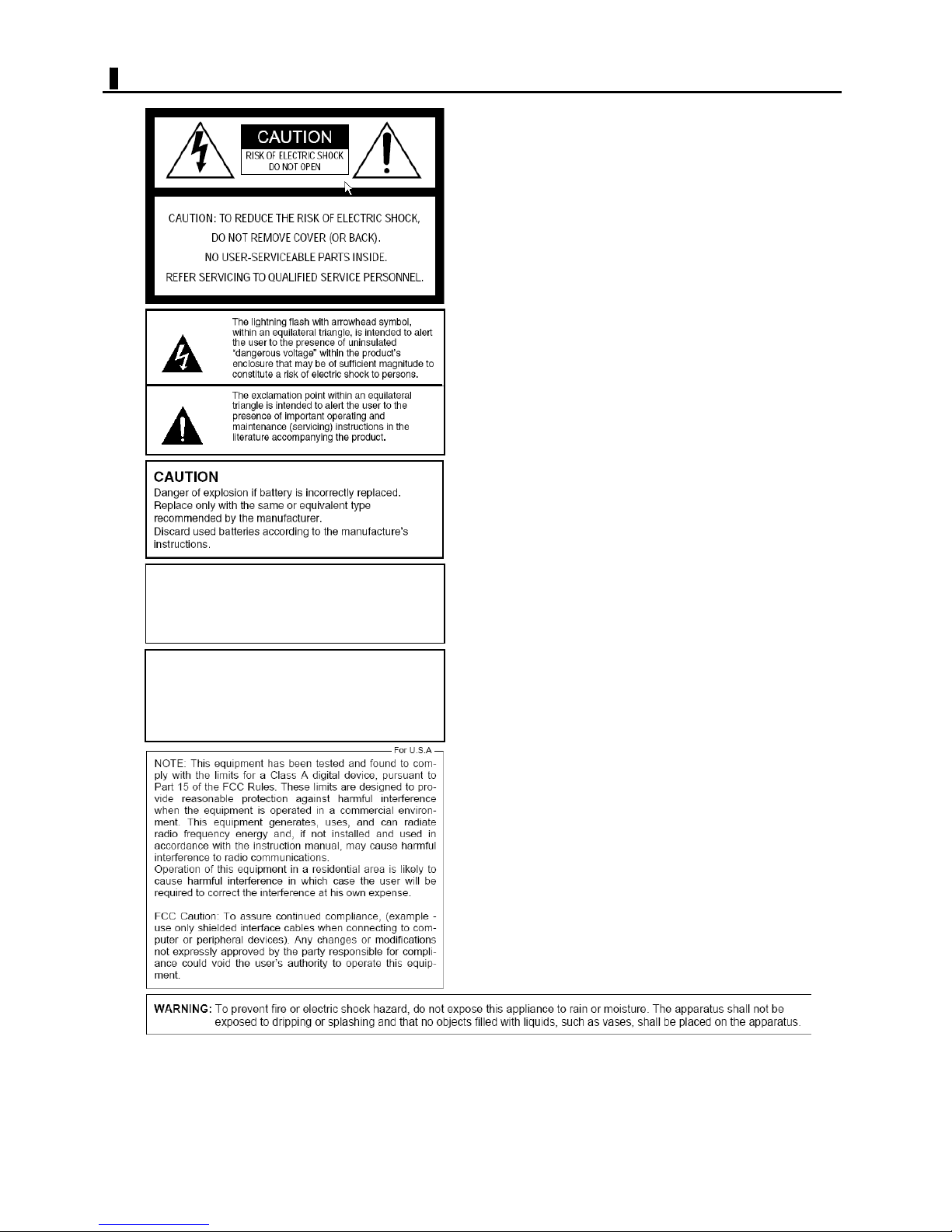
IMPORTANT
UG G
1) Read these instructions.
2) Keep these instructions.
3) Heed all warnings.
4) Follow all instructions.
5) Do not use this apparatus near water.
6) Clean only with dry cloth.
7) Do not block any ventilation openings. Install in
accordance with the manufacturer's instructions.
8) Do not use near any heat sources such as
radiators, heat registers, stoves, or other
apparatus (including amplifiers) that produce heat.
9) Do not defeat the safety purpose of the
polarized or grounding-type plug. A polarized plug
has two blades with one wider than the other.
A grounding-type plug has two blades and a third
grounding prong. The wide blade or the third
prong are provided for your safety. If the provided
plug does not fit into your outlet, consult an
electrician for replacement of the obsolete outlet.
10) Protect the power cord from being walked on
or pinched particularly at plugs, convenience
receptacles and the points where they exit from
the apparatus.
THIS PRODUCT HAS MULTIPLE-RATED
VOLTAGES.
ADJUST POWER INPUT SELECTOR SWITCH
PROPERLY ON REAR OF UNIT BEFORE
CONNECTING TO THE POWER SUPPLY.
The only way to disconnect power completely is to
unplug the power cord.
Make sure at least one end of the power cord is
within easy reach so that you can unplug the
computer when you need to
GG
11) Only use attachments/accessories specified by
the manufacturer.
12) Use only with the cart, stand, tripod, bracket,
or table specified by the manufacturer, or sold
with the apparatus. When a cart is used, use
caution when moving the cart/apparatus
combination to avoid injury from tip-overs.
13) Unplug this apparatus during lightning storms
or when unused for long periods of time.
14) Refer all servicing to qualified service
personnel. Servicing is required when the
apparatus has been damaged in any way, such as
power-supply cord or plug is damaged, liquid has
been spilled or objects fallen into the apparatus,
the apparatus has been exposed to rain or
moisture, does not operate normally, or has been
3
English
Page 4
FEATURES
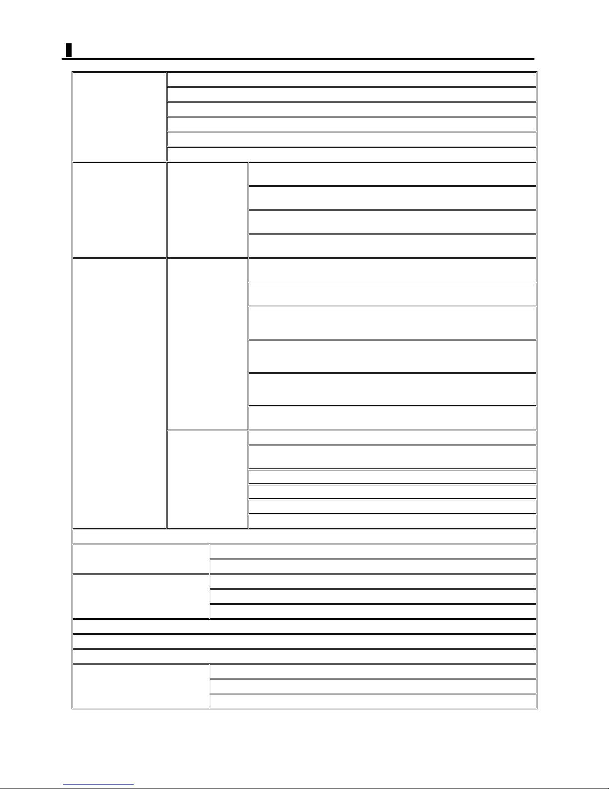
Selecting a screen layout
Switching live video automatically in order of camera numbers (Sequence)
Viewing live video
Recording video Recording
Searching and playing
back recorded video
Printing for video scenes using thumbnail images from recorded video.
Copying playback video
Backing up recorded data
Remote-controlling a PTZ camera
Emulating other DVR servers on network (Server to Server)
Viewing operation history (logs)
Configuring system settings
Viewing alarm video in single-screen layout when an alarm event occurs (Event Popup)
Viewing live video in full-screen mode (Enlarge)
Presetting the layout of video images from cameras (Camera Layout Preset Save)
Magnifying video (Zoom)
Normal recording
Records video continuously during the scheduled time period.
Motion recording
Records video whenever a motion is sensed in the target by the motion sensor.
Sensor recording
Records video whenever an alarm signal is input from an external sensor.
Text recording
Records video whenever a specific keyword is found in text from a POS or ATM.
Normal playback (One channel search)
Plays back the most-recent video by specifying the channel.
Date/Time search
Searches for video to play back by specifying the recording date and time.
Smart Search
Uses the motion sensor to search scenes containing any motion in the target
Operations
on Live screen
(Single-channel)
Operations
on SEARCH screen
(Multi-channel)
Copying a moving image (AVI)
Copying a still image (BMP or JPG)
Manual backup
Auto backup
Playing back backup data (Backup Viewer)
Configuring optional settings using ETC menu
Configuring detailed system settings on SETTINGS screen
Configuring system environment on Shell screen
area.
Map Search
Uses time bars to show recording information for all channels.
(You can specify the point to start playback by clicking on the desired time bar.)
POS Search
Searches for video and text by using keywords from among data recorded in
Text recording.
Event Search
Uses the alarm logs listed by event to search for video to play back.
Date/Time search
Detail Search (Panorama Search)
Searches for video scenes using thumbnail images from recorded video.
Smart Search
Map Search
POS Search
Event Search
4
English
Page 5
COMPONENT
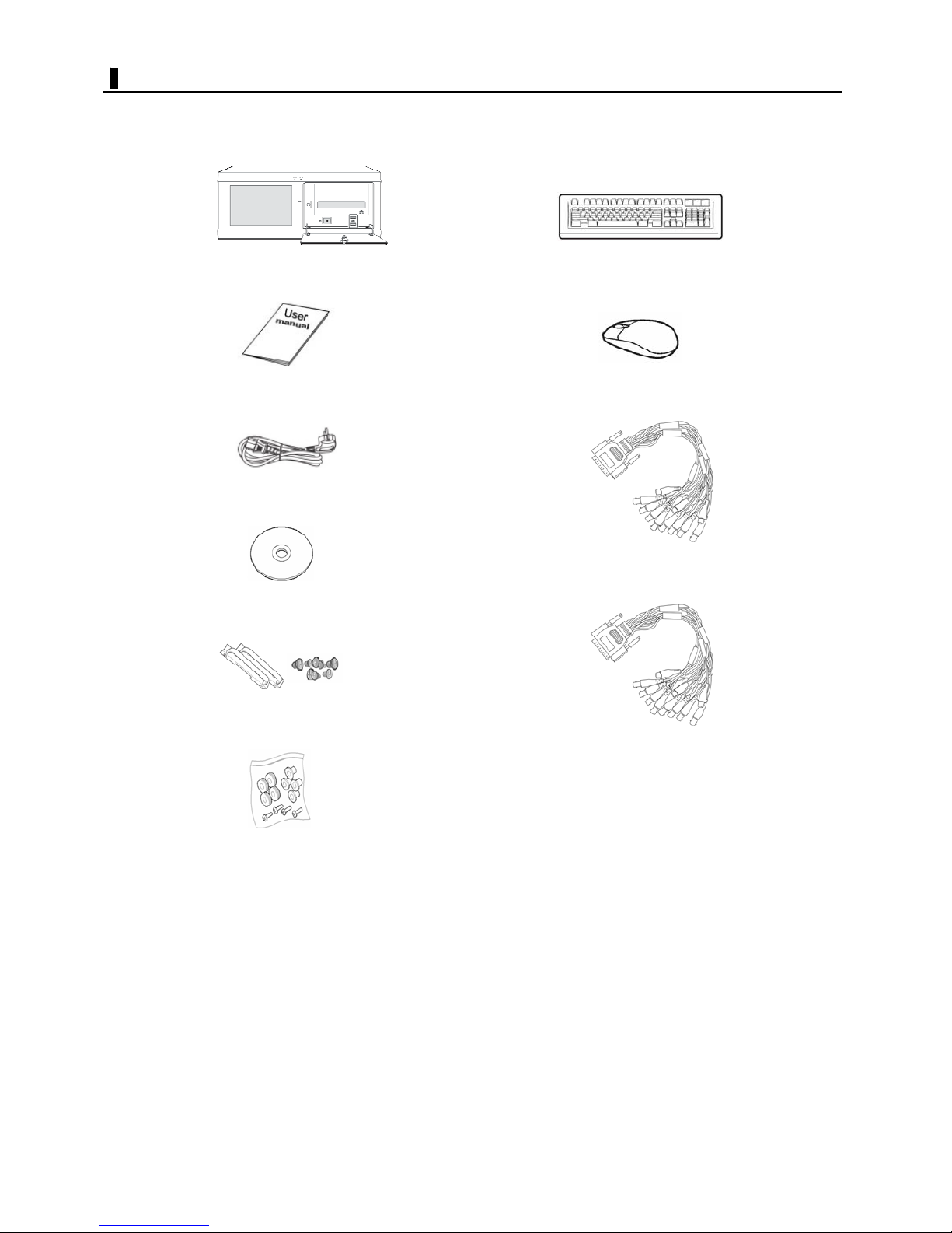
DVR package contains the main body and the following accessories.
GYU#
Xvhu#Pdqxdo#
Srzhu#Frug#
Surjudp#FG#
Nh|erdug#
Prxvh#
Ylghr#Fdeoh#+Rswlrq,#
Udfn#Prxqw#)#Vfuhz#
KGG#Il{lqj#Uxeehu#)#Vfuhz#
Please note that the components are subject to change without notification.
Dxglr#Fdeoh#+Rswlrq,#
5
English
Page 6
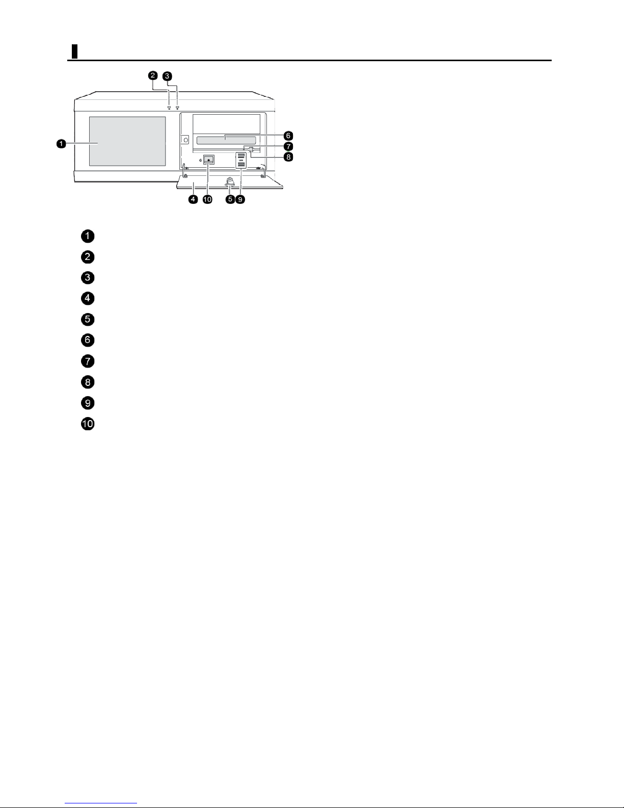
FRONT VIEW
Figure 1. Front View
Air duct
Power indicator
Access indicator
Drive panel
Drive panel key lock
CD/DVD drive
CD/DVD access indicator
CD/DVD eject button
USB terminal (2.0)
Power switch
Please note that the front figure and specification is subject to change without notification.
6
English
Page 7
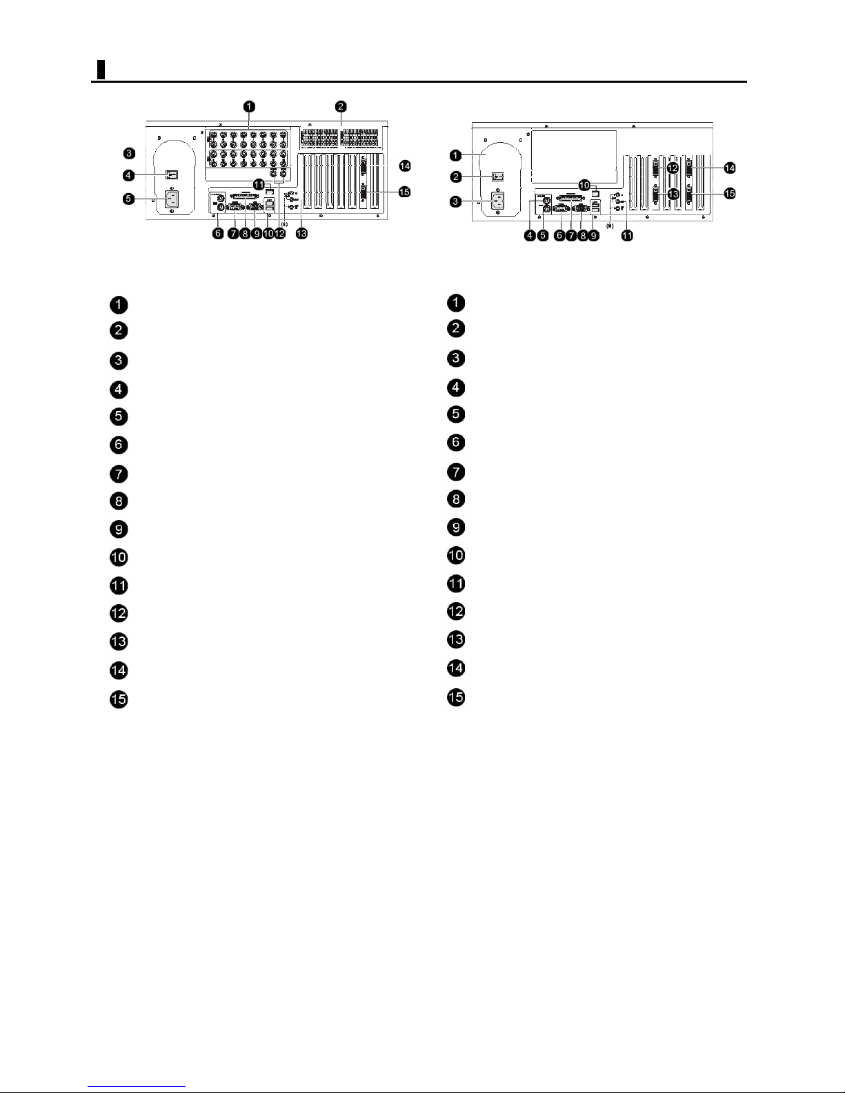
REAR VIEW
Figure 2. Rear View
I In/OUT terminals (video input/output)
ALARM IN/OUT terminals (alarm input/output)
Air duct
Standby switch
Power socket
MOUSE/KBD terminal (mouse/keyboard)
COM1 serial port
PRINTER port (printer)
VGA port (Monitor)
USB terminal (2.0)
LAN port
MON1/MON2 terminal (analog video output)
MIC/Speaker
Video input port
Audio input port
Air duct
Standby switch
Power socket
MOUSE terminal (Mouse)
KBD terminal (Keyboard)
RS-232 port
PRINTER port (printer)
VGA port (Monitor)
USB terminal (2.0)
LAN port
MIC/Speaker
Video input port
Audio input port
Digital out terminal (Alarm out)
Sensor terminal (Alarm in)
(*) The LINE IN/MIC IN terminals
Please note that the rear figure and specification is subject to change without notification.
(*) The LINE IN/MIC IN terminals
7
English
Page 8
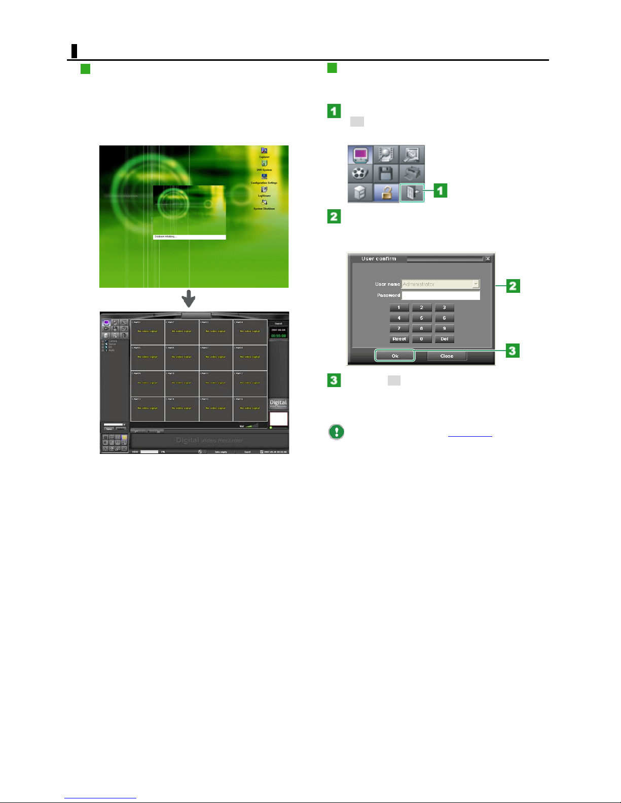
STARTING/SHUTDOWN
STARTING
Open the drive panel with the supplied key and power ON
the digital video recorder.
The startup screen appears and the digital video recorder
starts loading the system program.
When finished loading the program, the system presents
the default screen of [guest level].
SHUTDOWN
To shutdown the system, you must log into the
“Administrator” of system.
Click the [Exit] mode button.
The [Exit] mode button is only available on [LOG IN]
status of “Administrator”.
In the [Password] field, type a password of
“Administrator”.
You may use the numeric keypad.
Click the [OK].
The screen closes and the digital video recorder shuts
down automatically in approximately 15 seconds.
You may also click the [Go To Shell
SETTINGS screen to shut down the system.
] button on the
8
English
Page 9
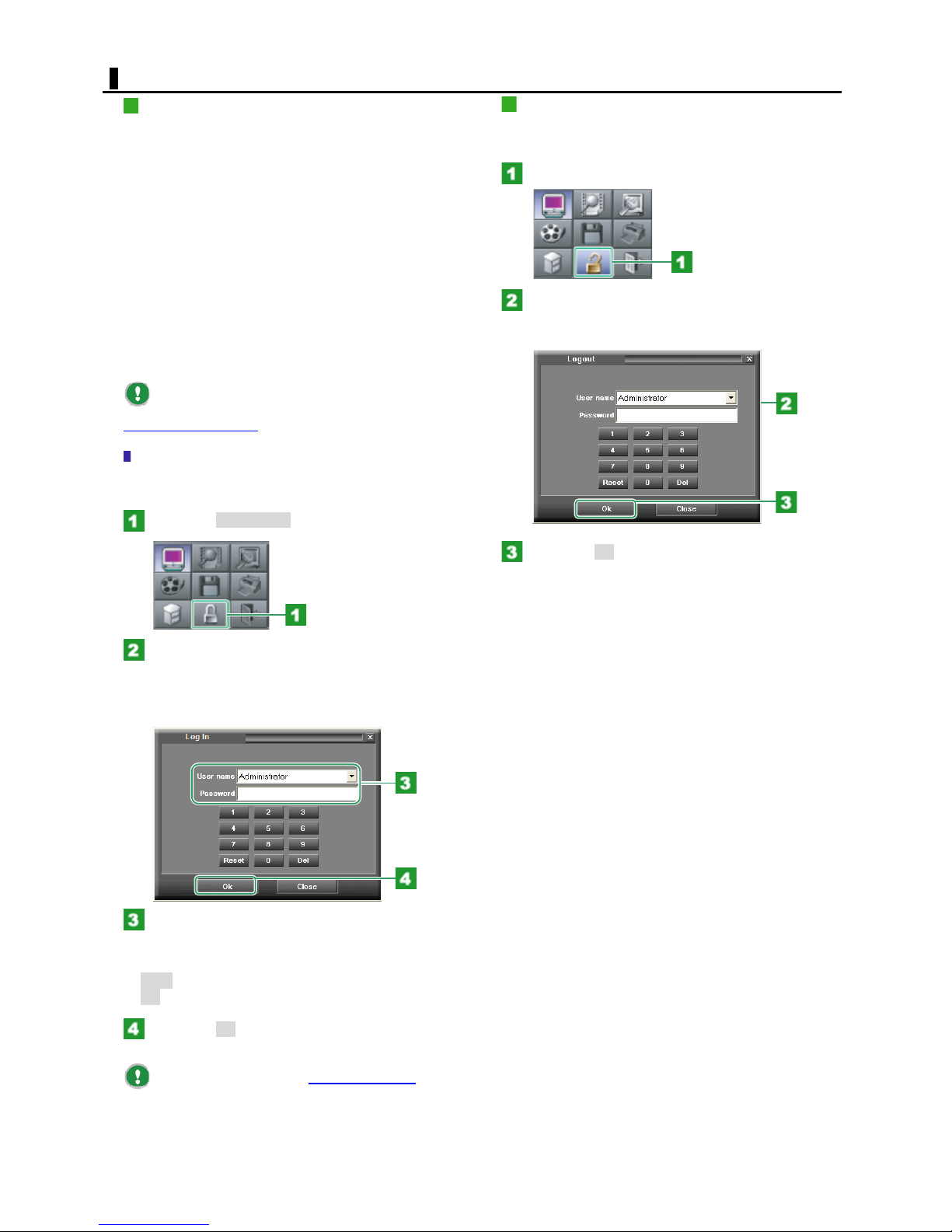
LOG IN/OUT
LOG IN
The digital video recorder is shipped with the following
two default user name settings.
If this is the first time you started the digital video
recorder, log into the system as "Administrator".
Guest:
By default, "Guest" is defined as a monitoring user. A monitoring
user can view video from all cameras, but has an operating authority
limited to working with the LIVE screen.
You may alter the operating authority of "Guest" in the
User/Password settings, accessible from the SETTINGS screen.
(By default, "Guest" has no password setting and can log into the
system without entering any password.)
Administrator:
"Administrator" has all operating authorities required for system
ration.
administ
(By default, Administrator has a password of "0")
To register a new user or change the password or
operating authority settings, you need to access the
User/Password settings
Logging into the system
To log into the system as a different user, you need to
perform the following operation on the [Live] screen.
Click the [Log In/Out] mode button.
from the SETTINGS screen.
LOG OUT
To log out of the system, you need to perform the
following operation on the [Live] screen.
Click the [Log In/Out] mode button.
In the [Password] field, type a valid password
for the selected user.
You may also use the numeric keypad.
Click the down-arrow button next to the
[User name] field.
The pull-down menu appears, showing all registered users.
Select the user name you want to use to log into the
system.
In the [Password] field, type a valid password
for the selected user.
You may also use the numeric keypad.
Reset:
Del:
Clears all characters you typed.
Clears the last character you typed.
Click the [OK].
You are successfully logged out of the the system. The
digital video recorder returns to the [Login] screen.
Click the [OK].
You are successfully logged into the system.
You may configure the [Auto login options
in the User/Password settings accessible from the
SETTINGS screen. This eliminates the need for entering a
password because you automatically log into the system
with the user name and camera layout settings you
specified after power ON.
] setting
9
English
Page 10
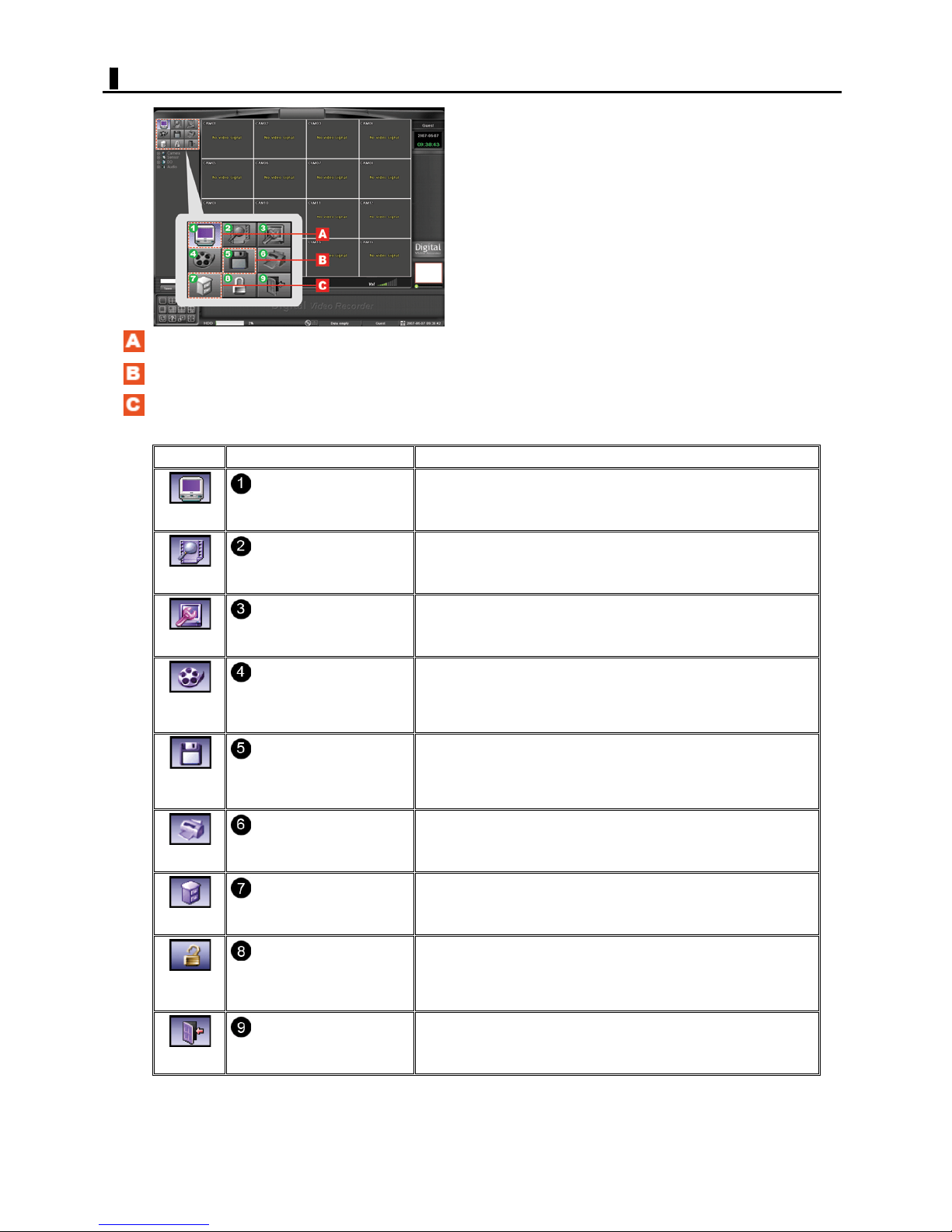
MODE BUTTON
Currently selected button: Shown with a purple background.
Unselectable button: Shown with a black icon.
Selectable button: Shown with a gray icon.
Button Displayed Screen/Menu Operation Description
Displays the LIVE screen, where a monitoring user can monitor live video.
DISPLAY
LIVE screen
SEARCH screen
SEARCH
Besides monitoring live video, these users can perform one-channel
search, and other operations.
Displays the SEARCH screen, where you can search for recorded video for
playback.
On this screen, you can playback more than one recorded video
simultaneously on a multiple-screen display.
CONFIG
DATA
BACKUP
DATA
SAVE
PRINT
ETC
LOG
IN/OUT
EXIT
CONFIGURATION(SETTINGS)
screen
Manually Backup screen
Manually Backup screen
Print screen
ETC menu
Log In screen / Log Out screen
Exit screen
Displays the CONFIGURATION screen used by the users with this authority.
These users can configure various settings for the system.
Displays Manually Backup screen, where you can back up recorded video
onto a recording media such as a CD-ROM, DVD, or removable hard disk.
(This button is only accessible from the LIVE screen only.)
Displays the Copy screen, where you can copy playback video.
Video data is copied using the AVI (for moving images) or BMP/JPG (for still
images) format.
(This button is accessible from the SEARCH screen only.)
Displays the Print screen, where you can print playback video.
(This button is accessible from the SEARCH screen only.)
Displays a pull-down menu that provides various options.
Displays the Login Screen, where you can log out of the system.
Shuts down the system.
10
English
Page 11
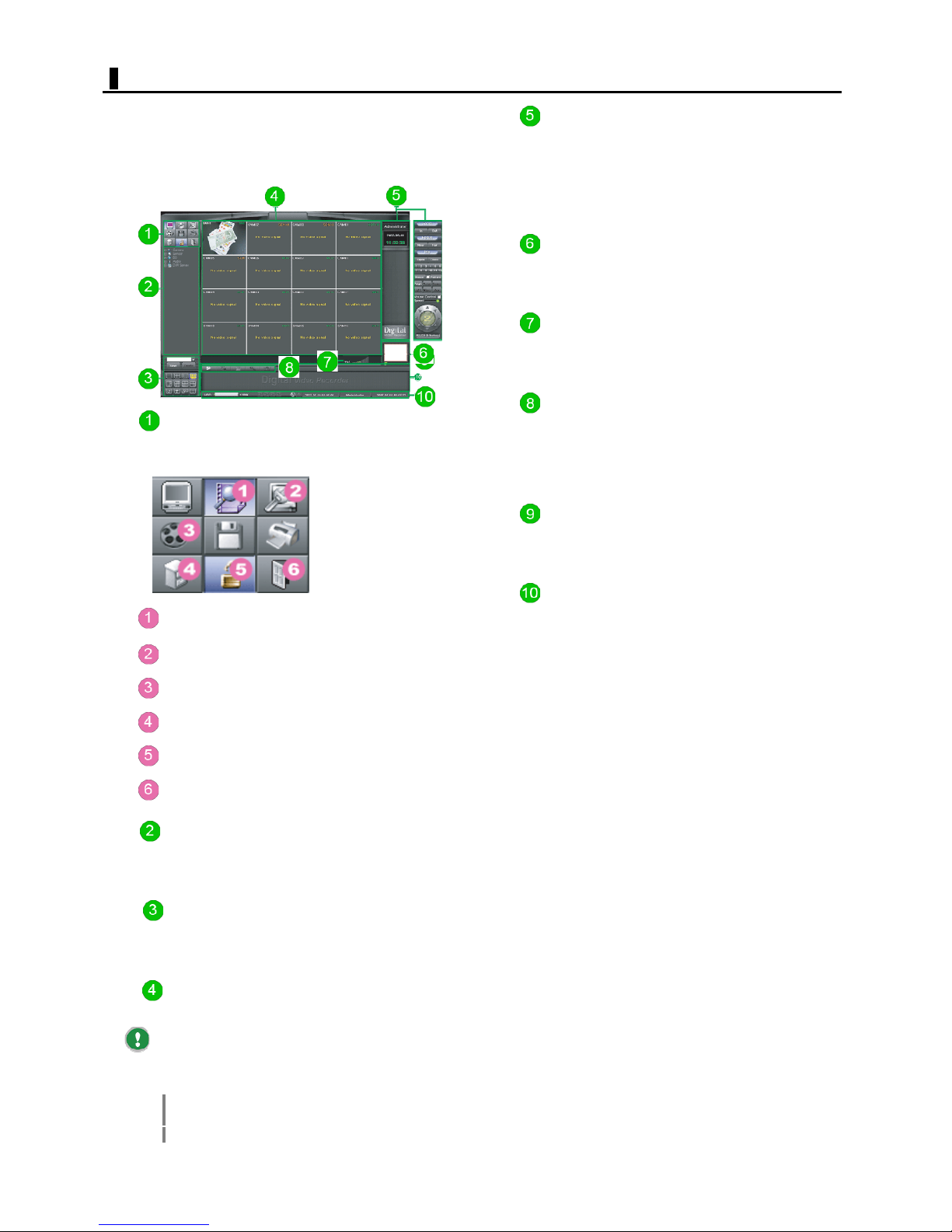
LIVE COMPONENTS
The LIVE screen appears first after you log into the
system.
On this screen, you can monitor live video, operate a PTZ
(Pan/Tilt/Zoom) camera, and playback of recorded video
from a selected channel.
Mode Buttons
On the LIVE screen, the following Mode buttons are
available.
Camera Control Panel
Switching to a single-screen layout when you monitor
video from a PTZ camera causes the Camera Control panel
to appear to enable remote control.
When this panel is not displayed, the current date and
time are shown.
Zoom Panel
You can perform zoom-in and zoom-out operations when
you monitor video from a camera in a single-screen layout.
Audio Volume
You can adjust the sound volume for the channel for
which audio output is set to "ON".
Search Menu Buttons
When the LIVE screen appears, only the [One Channel
Search] button is usable.
cking the [One Channel Search] button, however,
Cli
enables you to use all buttons in the Search menu.
Search Panel Display Area
Clicking the [One Channel Search] button causes the
Search panel to appear.
SEARCH button Displays the SEARCH screen.
CONFIG button Displays the SETTINGS screen.
DATA BACKUP button Displays the Backup screen.
ETC button Displays the pull-down menu.
LOG IN/OUT button Displays the Log in/out screen.
EXIT button Displays the exit screen.
Camera Information
Camera information for all channels is listed in a tree
format.
Screen Selection Buttons
Use these buttons to switch the screen layout or the
display method.
Video Display Area
Live video is displayed here.
If no camera is connected, the following message
appears based on the camera type (in [Camera]) you set
in the Camera settings accessible from the SETTINGS
screen:
CCD: No video signal
Network: Disconnection
None: Logo
Status Bar
The status bar shows inform action such as hard disk
usage and the connection statuses of the network device
or recording medium.
11
English
Page 12
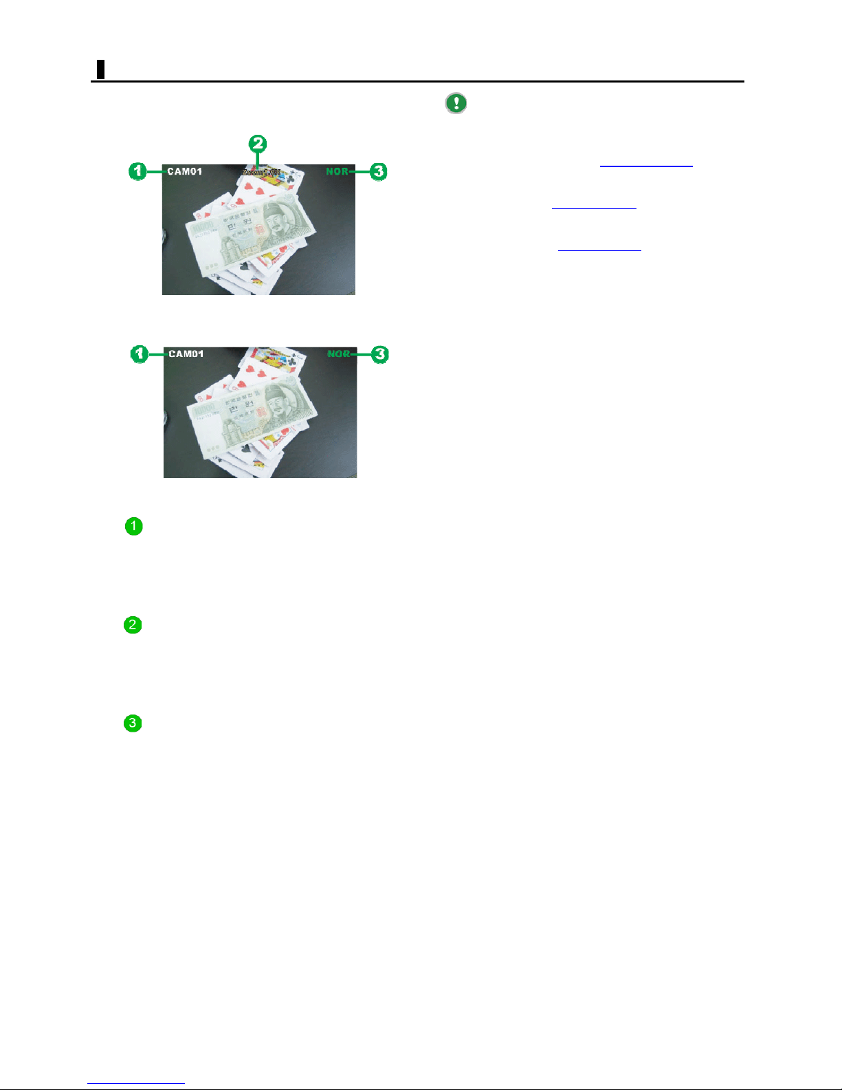
DISPLAY INFORMATION
On the LIVE screen, live video from the connected
cameras is displayed in the video display area.
Each video is displayed with the following information.
Display example for single-screen layout
The "NOR" (Normal recording) indicator is not
shown when the normal recording is performed
simultaneously with the Motion, Sensor, or Text recording.
To set the Normal, Motion, Sensor, or Text
recording mode, access the Schedule settings
SETTINGS screen.
To set the Pre-alarm recording mode, configure the
[Pre] setting in the Camera settings
screen.
To set the Audio recording mode, configure the
[Audio] setting in the Camera settings
screen.
from the SETTINGS
from the SETTINGS
from the
Display example for multiple-screen layout
Camera Title
This is the camera title you configured in the [Camera
Title] setting, which can be accessed from the SETTINGS
screen.
Default setting: CAM01 to CAM16
Zoom Magnification
The current zoom magnification (up to 3 times) is shown
here when you monitor video in a single-screen layout.
To change the zoom magnification, operate the zoom
slider.
Recording Mode
The current recording mode is shown here.
NOR: Normal recording
MOT: Motion recording
SEN: Sensor recording
TXT: Text recording
M/S: Simultaneous Motion/Sensor recording
M/T: Simultaneous Motion/Text recording
S/T: Simultaneous Sensor/Text recording
M/S/T: Simultaneous Motion/Sensor/Text recording
A: Audio recording
12
English
Page 13
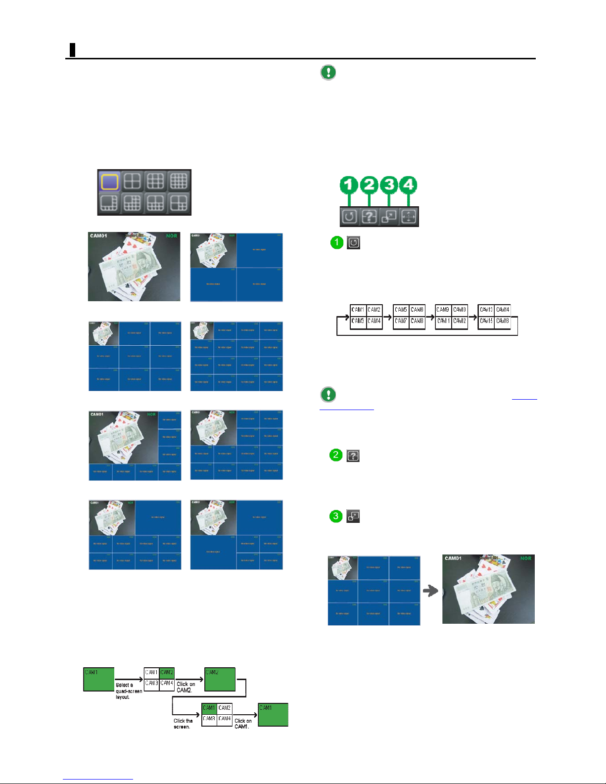
SCREEN LAYOUT
To switch the screen layout or the display method of the
video you are monitoring, use the Screen Selection
buttons.
The currently selected button is shown with a purple icon.
Screen Layout
Besides the single-screen display, you can select seven
types of multiple-screen layouts.
In the default layout, each screen displays live video in the
order of camera numbers.
Single Screen (1X1) Quad Screen (2X2)
9-Screen (3X3) 16-Screen (4X4)
Although the system shows a 16-screen layout
when powered ON, if you log out and then log in again, it
will restore the screen layout setting used when you
logged out.
However, if you shut down the system or switch to
the Shell screen, the system will show the 16-screen
layout when you log in, just as when started up.
Display Method
Button to switch screen (Sequence)
Clicking this button automatically switches the displayed
live video to the next images in the order of camera
numbers, using the screen layout being selected.
<Display example for quad-screen layout>
8-Screen (main1+sub7) 13-Screen (main1+sub12)
10-Screen (main2Xsub8) 7-Screen (main3Xsub4)
Click on a screen to switch between the single-screen and
multiple-screen layouts.
Clicking in a multiple-screen layout: The clicked video
appears in a single-screen layout.
Clicking in a single-screen layout: The previously
selected multiple-screen layout is restored.
Example:
To stop the auto screen switching, click the [Sequence]
button again.
You may use other Screen Selection buttons to stop the
auto screen switching.
To set the screen switching time, select [Layout
sequence time] in the ETC menu.
The auto screen switching feature is not available in
the 16-screen layout mode.
Button to initialize the screen layout
(User layout)
Use this button to restore the default screen layout (in
order of camera numbers) when using a preset camera
layout.
Button to switch screens when an alarm
event occurs (Event popup)
Selecting this button causes the alarm video to appear in a
single-screen layout, if an alarm event occurs.
Normal display Event popup
The previous screen will be restored as soon as the set
event popup time is elapsed.
To disable the Event Popup feature, click the button again.
13
English
Page 14
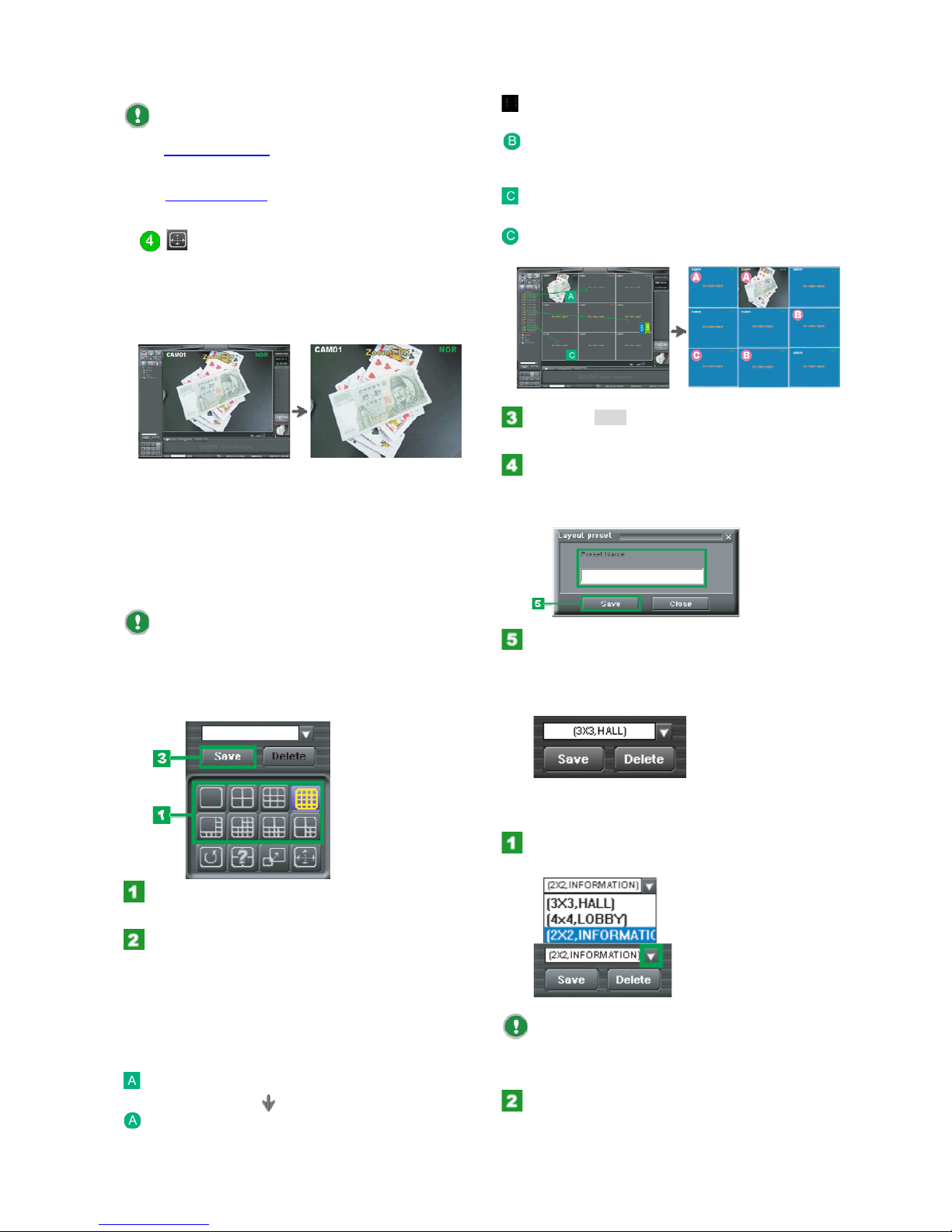
SCREEN LAYOUT
To enable the Event Popup feature, set the Motion,
Alarm IN, or Text recording mode for the desired channel
in the Schedule settings
screen.
To set the time during which alarm video is displayed,
select [Event popup time
accessible from the SETTINGS
] in the ETC menu.
Drag Camera01 to the CH2 (Camera02) position.
Camera02 is replaced with Camera01.
Drag Camera01 to the CH2 (Camera02) position.
Button to switch to the full-screen mode.
(Enlarge)
Clicking this button (or right-clicking on a screen) causes
only the camera's image to appear in the maximum
display size of the monitor, using the screen layout being
selected.
Normal screen mode Full screen mode
Right-click on a full-screen display to return to the normal
screen mode.
Presetting Camera Layouts
You can configure and preset the video layouts of your
cameras according to your preference.
The configured camera layouts can be preset on a
user basis.
In other words, you cannot display camera layouts
preset by other users.
Presetting a camera layout
Camera02 is replaced with Camera01.
Click the [Save].
The [Layout preset] dialog box opens.
In the [Preset Name] field, type a name (up to
10 characters) for the camera layout.
Notice that, in the [Preset Name] field, the display symbol
of the selected screen layout has been filled automatically.
Click Save in the dialog box.
The configured camera layout is preset and its preset
name is added to the pull-down menu.
If any duplicated preset name exists, re-enter a correct
preset name according to the displayed message.
Using the Screen Layout buttons, select the
screen layout in which you want to place video.
In the Camera Information panel, open the
[Camera] folder, select a camera number, and drag
it to the desired position.
The video in that position is now replaced with that of the
camera you dragged.
Example of camera layout configuration in 9screen layout
Drag Camera01 to the CH2 (Camera02) position.
Camera02 is replaced with Camera01.
Switching to a preset camera layout
Select the preset name of the camera layout.
The layout switches to the specified camera layout.
Note that the pull-down menu shows only the
preset
names of the camera layouts preset by the user
currently logged in.
Those preset by other users are not shown.
Click the [User Layout] button.
The previous camera layout (in the order of camera
numbers) is restored.
14
English
Page 15
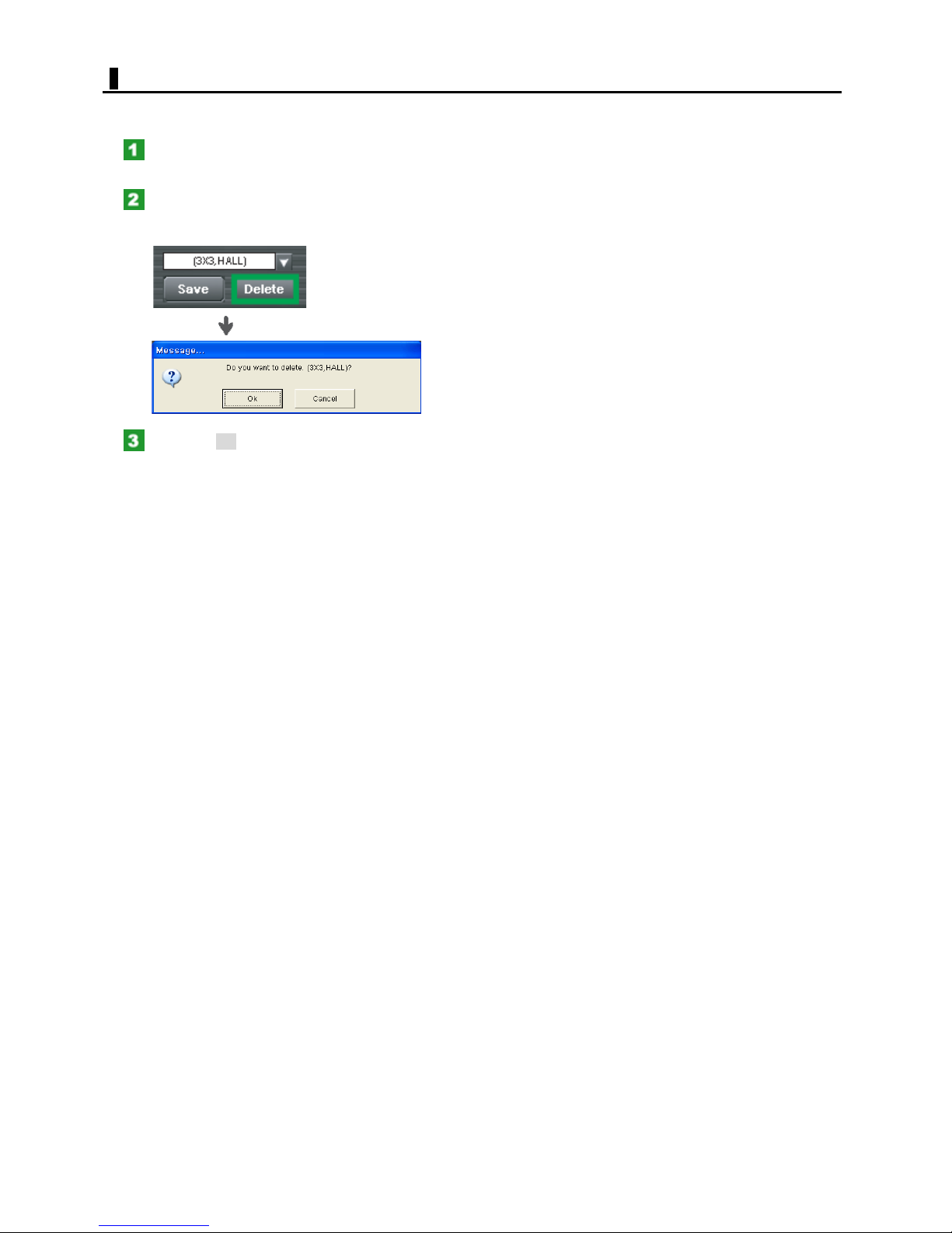
SCREEN LAYOUT
Deleting a preset camera layout
Select the preset name of the camera layout
you want to delete.
Click Delete.
The deletion confirmation dialog box opens.
Click the [OK].
The selected preset name disappears from the pull-down
menu.
15
English
Page 16
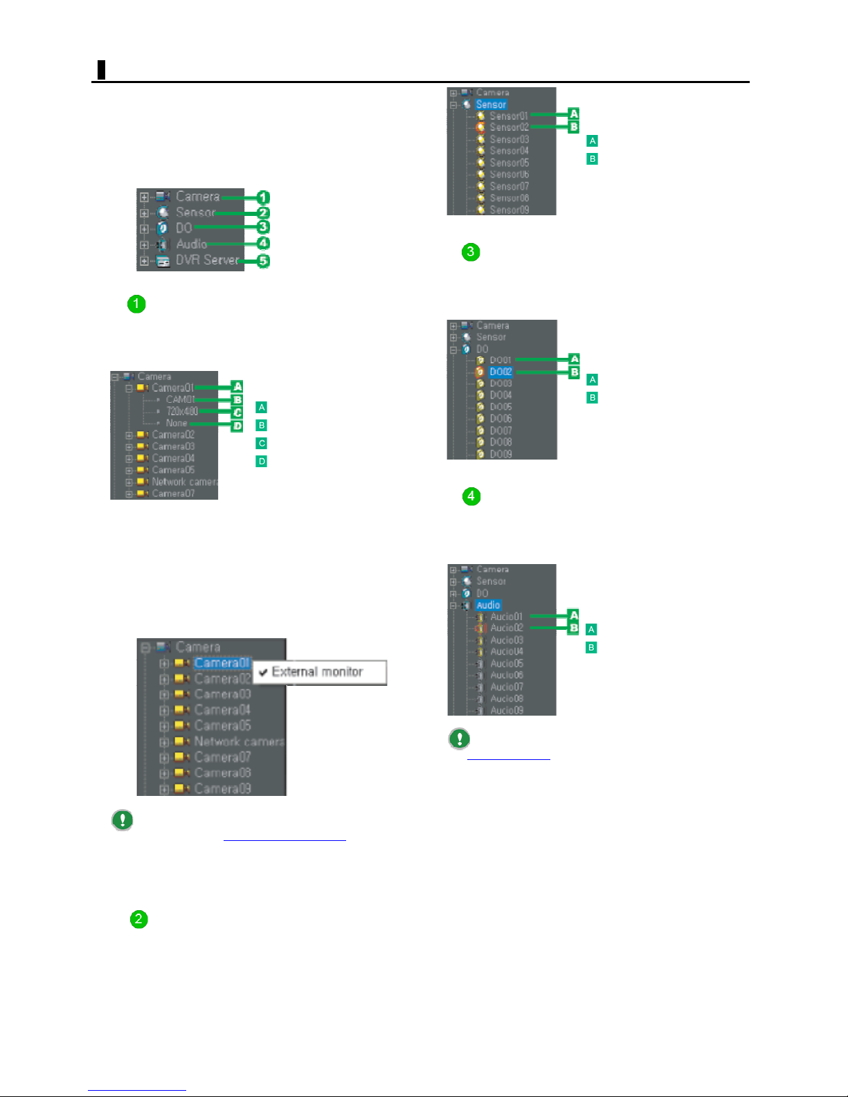
CAMERA INFORMATION
Camera information for all channels is listed in a tree
format.
The tree list contains five folders, each of which can be
opened and closed by clicking the +/- button (or doubleclicking the folder name/camera title).
By opening each folder, you can view and change settings
for that camera from the context menu.
[Camera] folder
Viewing camera settings
Open this folder to view the camera settings configured in
the Camera settings accessible from the SETTINGS screen.
Camera number
Camera title
Resolution
Protocol
No sensor input
Sensor being input
[Digital OUT] folder
This folder contains the alarm output settings.
Right-click the desired Digital Out (Alarm OUT) number
and, in the context menu, turn On/Off the alarm output.
Digital output is "Off".
Digital output is "On".
Setting in the context menu
Set which camera's image you want to view on the spot
monitor connected to the digital video recorder.
To do so, right-click the desired camera number and, in
the context menu, select or deselect [External monitor ] to
turn On (a checkmark appears) or Off (a checkmark
disappears) the output to the spot monitor, respectively.
If you set the External Monitort mode to "Fixed
Mode" by selecting [External Monitor mode
menu, you can specify only one camera to output video
signals to the spot monitor (Default setting: Camera01).
Note that you cannot specify network cameras.
] in the ETC
[Audio] folder
This folder contains the audio output settings.
Right-click the desired Audio number and, in the context
menu, turn On/Off the audio output.
Audio output is "Off".
Audio output is "On".
To enable the audio output, set [Audio] to "ON" in
the Camera settings
Note that you can turn "ON" the audio output for
only one camera.
These settings are provided solely for audio output
and do not affect the audio recording behavior you
configured in the [Audio] setting in the Camera settings.
accessible from the SETTINGS screen.
[Sensor] folder
Open this folder to view the state of alarm inputs from
external devices in the order of Sensor numbers.
16
English
Page 17
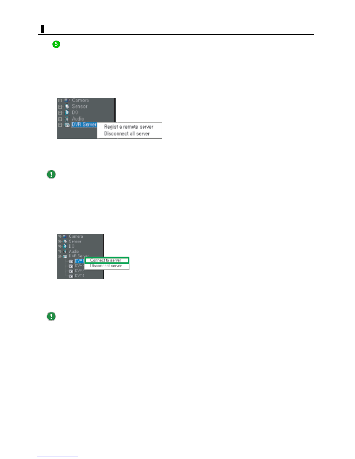
CAMERA INFORMATION
[DVR Server] folder
This folder contains information on networked DVR servers.
You can right-click this folder to perform operations
related to the "DVR Server" feature from the context
menu.
Operations on the folder
Right-clicking the [DVR Server] folder allows you to
perform the following operations from the context menu.
Register a remote DVR: Displays the [Server List] screen
for DVR server registration.
Disconnect all remote DVR: Disconnects all DVR servers
currently connected.
You may also register DVR servers in the [Register
a remote DVR] setting, accessible by selecting [DVR
Server] from the ETC menu.
Operations on a DVR server
Opening the [Server to Server] folder reveals the
registered DVR servers.
You can then right-click the desired DVR server to perform
the following operations from the context menu.
Connect to remote DVR: Establishes a connection to the
selected DVR server.
Disconnect remote DVR: Disconnect the selected DVR
server.
When connected, DVR servers are shown with a red
border.
17
English
Page 18
ZOOM/AUDIO
ZOOM
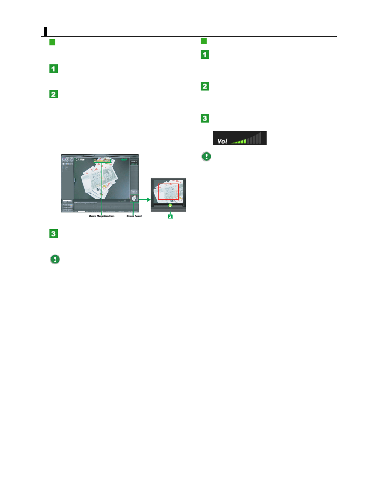
In a single-screen layout, you can perform zoom-in and
zoom-out operations.
Click the camera's video you want to zoom in.
In the Zoom panel, a thumbnail of the selected video
appears.
Operate the zoom slider.
Move the slider to the right to increase the zoom
magnification.
AUDIO
In the Camera Information panel, open the
o] folder and right-click the desired channel.
[Audi
Note that you can turn "ON" the audio output for only one
channel.
Then, in the context menu, set the audio output
to "ON".
The speakers connected to the digital video recorder start
sounding.
The current zoom magnification (1.00 to 3.00
times) is shown in the lower right of the screen.
The red rectangle on the thumbnail video indicates
the area you currently zoom in.
Click the video again.
Now, the video layout returns to the existing layout before
zooming in.
When using a network camera, no thumbnail image
is shown on the Zoom panel.
Adjust the sound volume using the volume
control.
To enable the audio output, set [Audio] to "ON" in
the Camera settings
Although the digital video recorder can record audio
signals from up to 16 channels, its output to speakers is
limited to only one channel.
The sound may not output in sync with the video
images.
accessible from the SETTINGS screen.
18
English
Page 19
PTZ
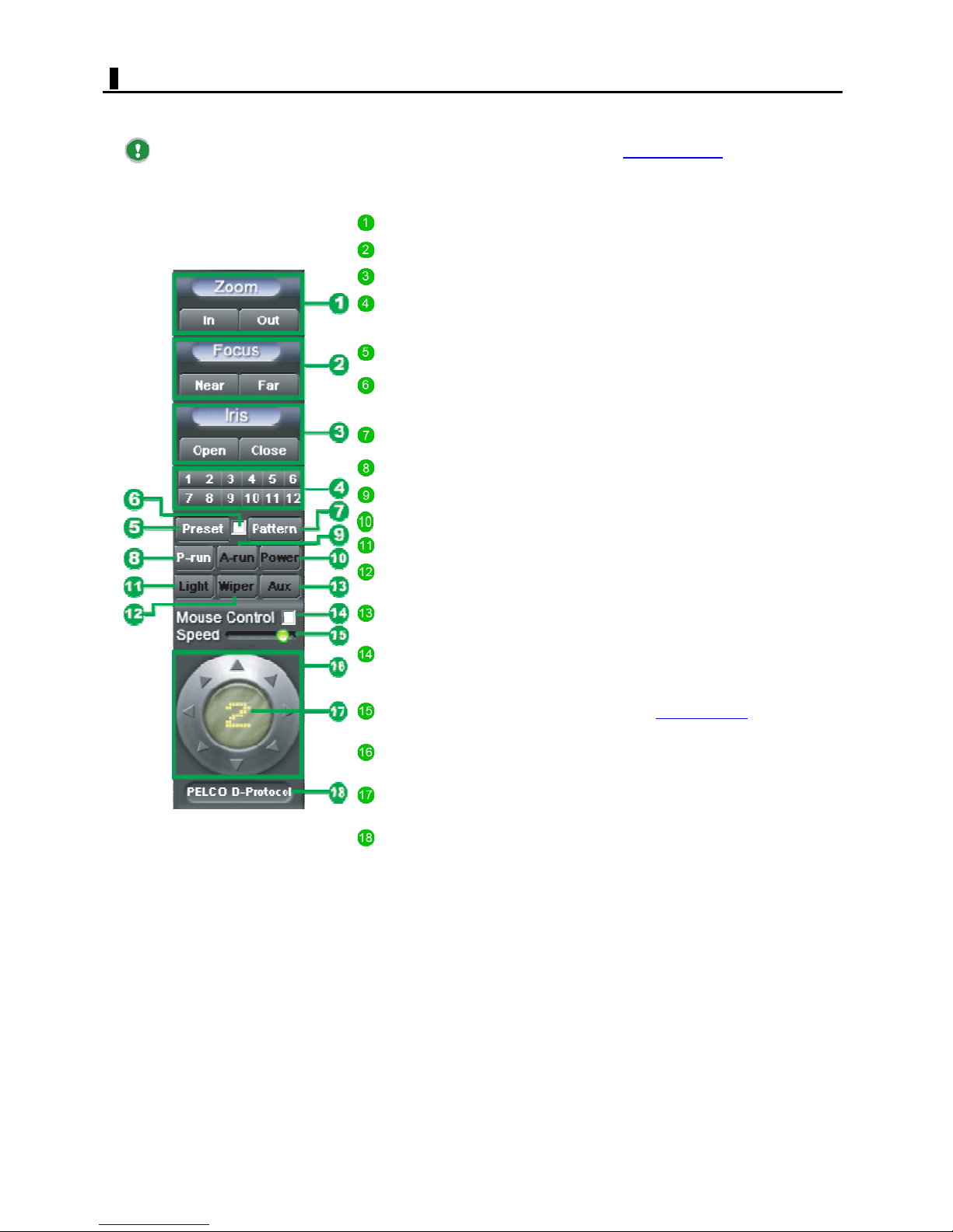
When you monitor video from a PTZ camera in a single screen layout, the Camera Control panel is shown.
Now, besides normal PTZ operations, you can register preset positions and auto panning patterns.
Before performing PTZ operations, configure the [Protocol] setting in the Camera settings
SETTINGS screen.
The features you can control using the Camera Control panel depend on the camera model.
Zoom
Focus
Iris
Preset
numbers
Preset
Registration
check box
Pattern
P-Run
A-Run
Power Use this button to turn it off.
Light
Wiper
Aux
Mouse
control
Speed
Use In/Out to zoon tell/wide the video.
Use Near or Far to adjust the focus.
Use Open or Close to adjust the iris.
Use these buttons to select a registration number for each
preset position.
Use this button to register a preset position or orient the
camera to a preset position.
Select this check box to enable the registration of a preset
position or auto-panning pattern.
Use this button to register an auto-panning pattern or auto-pan
the camera in a registered pattern.
Use this button to start a preset run.
Use this button to start an auto run.
Use this button to turn the light on/off.
Use this button to turn the wipter on/off.
Reserved for additional features.
(For how to use these buttons, consult the dealer from which
you purchased the digital video recorder.)
Select this check box to use the mouse to control the camera
orientation.
Use this slider bar to set how fast you can move around on the
image during panning/tilting or screen shooting
The speed increases as you move the slider bar to the right.
accessible from the
.
PAN/TILT
controller
Camera
number
Protocol
information
Use this control to adjust the orientation of the camera.
The currently selected camera number is shown.
The currently selected PTZ protocol is shown.
19
English
Page 20
PTZ
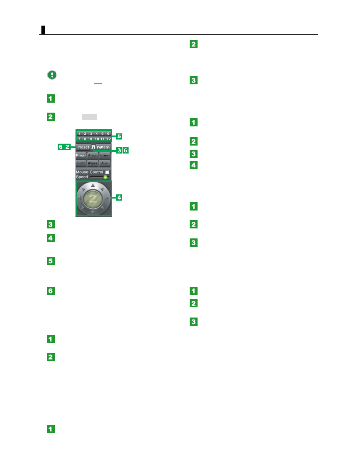
Registering a preset position
Camera states such as the orientation and zoom
magnification can be registered as preset positions. You
can register up to 12 preset positions.
The preset positions may also be registered and
deleted from the [PTZ
accessible from the SETTINGS screen.
Click the camera's video.
The video image is now displayed in a single-screen layout.
Click the [Preset].
The button is now highlighted.
] tab of the Camera settings
Click P-Run.
The button is highlighted and the camera starts a preset
run.
During a preset run, the preset number for the current
position is highlighted.
Click P-Run again.
The button returns to the normal display (no more
highlighted) and the preset run stops.
Deleting a preset position
Click the camera's video.
The video image is now displayed in a single-screen layout.
Click Preset.
Select the Registration check box.
Set the camera orientation using the PAN/TILT
controller.
Adjust also the zoom, focus, and iris settings as required.
Select a preset number.
The selected preset number is used to register camera
states such as the current orientation and zoom
magnification as a preset position.
Click Preset and deselect the Registration check
box.
The button returns to the normal display (no more
highlighted). The preset position has been registered.
Moving the camera to a preset position
Click the camera's video.
The video image is now displayed in a single-screen layout.
Deselect th
Select the preset number you want to delete.
The selected preset position has been deleted.
Starting an auto run
Runs an auto panning pattern registered on the camera.
Click the camera's video.
The video image is now displayed in a single-screen layout.
Click A-Run.
The camera starts an auto run.
Click Aux.
The auto run stops.
Controlling the mouse
Instead of using the PAN/TILT controller, you can use the
mouse to change the camera orientation.
Select a camera.
Select the [Mouse control] check box.
Now, you can use mouse to control the camera.
Click the left mouse button and move the
mouse while holding down the left mouse button.
The camera orientation changes according to the mouse
movement.
Use the [Speed] slider to adjust the mouse control speed.
e Registration check box.
Select a preset number by clicking.
The camera orientation has been set to the registered
preset position.
Starting a preset run
You can monitor what's happening by moving the camera
through two or more preset positions in the order of
preset numbers.
Click the camera's video.
The video image is now displayed in a single-screen layout.
Shooting the screen
If you are using a three-button mouse, clicking the center
mouse button causes the camera orientation to change so
that the clicked point appears at the center of the screen.
20
English
Page 21
INFORMATION BAR
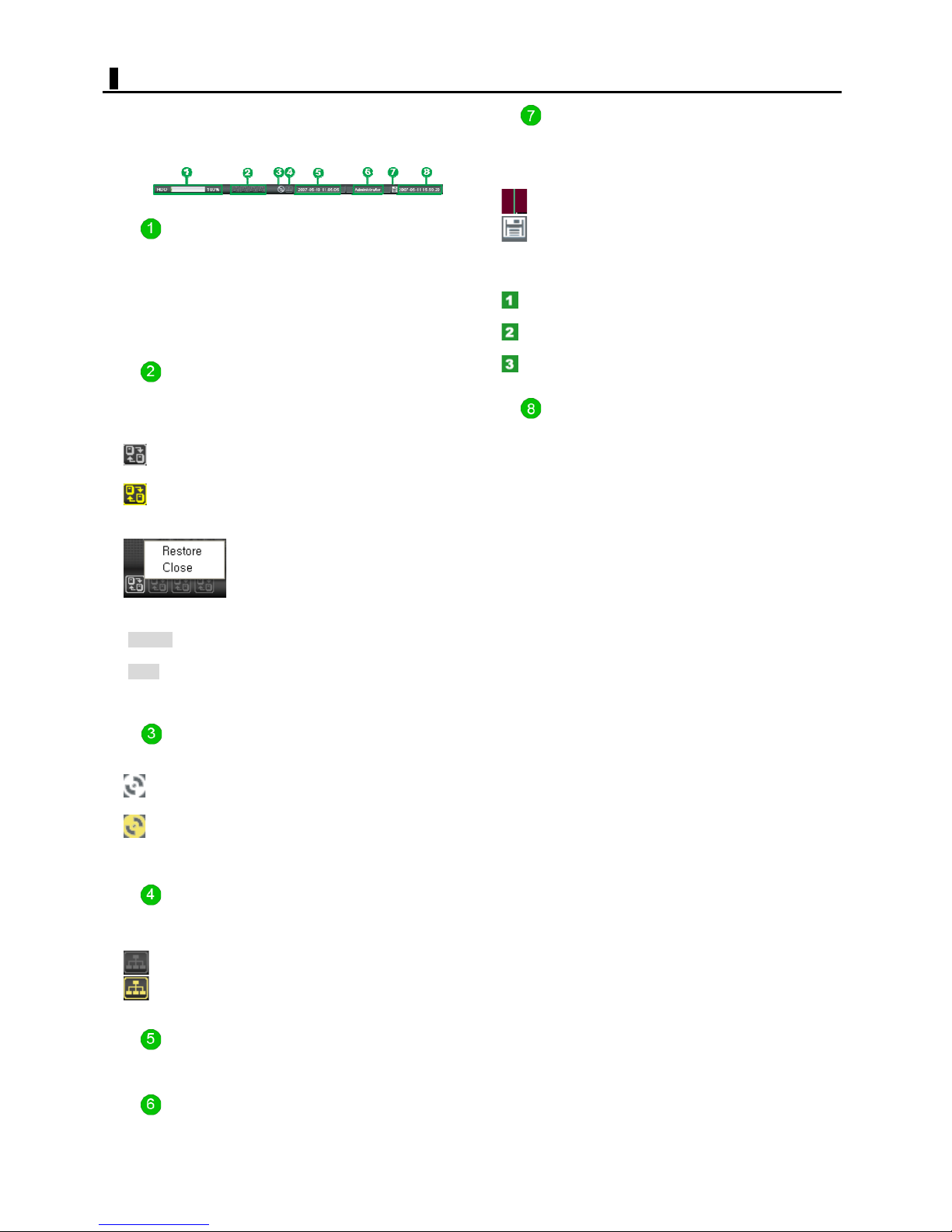
The status bar shows information such as hard disk usage
rate, DVR server connection, backup status, network
connection status, the oldest recorded time, Log in user,
usb connection, and current time.
Digital video recorder's hard disk drive
Information
The disk usage will be shown in percentage.
Recorded data will be stored to 64-magabyte files for each
camera.
If the drive usage indication reaches 100%, the system
will overwrite the oldest recorded data file in order.
"DVR Server" connection status
The color of each icon indicates the connection status of
the DVR server and the display status of the [Server to
Server] screen.
(White): Connected with the [DVR Server] screen
displayed.
(Yellow): Connected with the [DVR Server] screen
minimized.
USB device connection status
Connecting a USB device to one of the USB ports of the
digital video recorder changes the appearance of the icon
as follows.
(No icon): USB device is not connected.
(White): USB device is connected.
To disconnect any USB device, perform the following
operation.
Click on the icon. The [Stop USB Mass Storage Device
- Drive: (F)] box appears.
Click on the displayed box. The USB device is
disconnected and the [Message] dialog box opens.
Click OK and remove the USB device.
Current date & time
Show the current date/time
: Right-clicking these icons invokes the
context menu that shows the "Restore" and "Close"
commands.
[Restore]: Restore the minized screen window of the [DVR
Server] to the standard size.
[Close]: Disconnect the network connection with the [DVR
Server].
Data backup operation status
The color of this icon indicates the data backup operation
status and the display status of the [Backup] screen.
(White): Backup is not in progress with the [Backup]
screen.
(Yellow): Backup is in progress with the [Backup]
screen.
Network connection status
When a cleint or CTMS user is connected, the color of the
icon changes.
(Grey): Not connected with Client or CTMS user.
(Yellow): Connected with Cleint or CTMS user.
Oldest recording date and time
Show the oldest recorded data and time
Login user name
Show the current log in user
21
English
Page 22
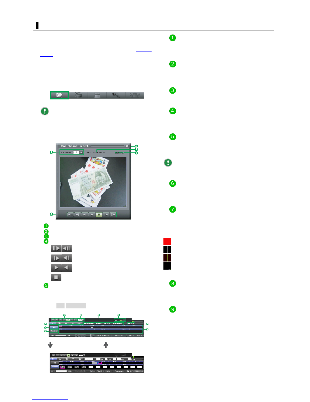
1CH SEARCH
On the LIVE screen, you can playback recorded video by
specifying a single channel.
To play back video from more than one channel
simultaneously, use the [Search menu] on the SEARCH
screen.
Playback buttons
For function of these buttons, refer to the explanation of
the playback buttons in the [One channel search] window.
[One channel search] window
In the [Search menu], click the [One Channel Search]
button. Then, the [One channel search] window appears
in the center of the screen, with the Search panel
displayed in the lower part of the screen.
If you are using a three-button mouse, doubleclicking the center mouse button also causes the [One
channel search] window to appear.
Functions of [One channel search] window
components
Channel selector (Channel)
Recording time (Hr/Min/Sec)
Recording mode
Playback buttons
: Go to the oldest /latest data.
: Frame-forward/rewind
: Forward/reverse playback
Playback speed indication
Shows the playback speed in six steps (?.5, 1.0, 2.0, 3.0,
4.0, and 5.0).
Audio volume control
Adjusts the audio output volume.
Search menu buttons
ck the [One Channel Search] button to make all buttons
Cli
selectable.
Date and time display/setting section
Shows the recording date and time of the playback video.
You can specify the recording date and time of the
playback video.
To select the recording date of the playback video,
click the Calendar button.
Channel selector (Ch)
Select the channel from which you want to playback
recorded video.
Map
Click this to show time bars (in hours/minutes) along the
time scale.
These time bars are colored according to the recording
mode.
: Normal recording
: Motion recording
: Sensor recording
: Text recording
: Stop
X : Closes the window.
Functions of Search panel components
Clicking Map/Thumbnail toggles the panel appearance as
shown below.
Click the [Thumbnail] button. Click the [Map] button.
Thumbnail
Click this to show 12 thumbnail images below the time
scale, each representing the video recorded at that time,
in an interval of 5 minutes.
Time scale
The recording time information is indicated as time bars or
thumbnails.
The current playback point is indicated with a red border.
Upper scale (hours): Display range = 1 day (Scale = 1
hour X 24)
Lower scale (minutes): Display range = 1 hour (Scale
= 1 minute X 60)
22
English
Page 23
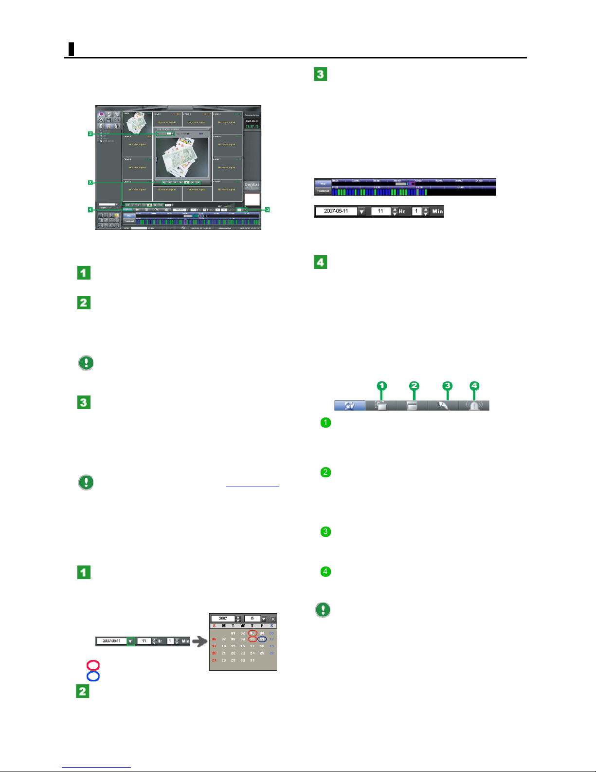
1CH SEARCH
Using one channel search
The following explains how to play back recorded video for
the channel you specify.
Normal playback
On the LIVE screen, click [One Channel Search].
e [One channel search] window opens.
Th
In the [One channel search] window, select the
camera number for the video want to play back in
the [Channel] field.
You may select the camera number using the channel
selector ("Ch") on the Search panel.
When the [One channel search] window opens, you
may notice that the camera number you selected in the
single LIVE screen display is already set.
In the Search panel, specify the point at which
you want to start play back by clicking the desired
time bar.
Use the upper time bars to specify the playback start point
in units of hours.
Use the lower time bars to specify the playback start point
in units of minutes.
Alternatively, in the date/time setting section, you may
directly specify the hour (Hr) and minute (Min) values of
the playback start point.
or
You can view the video image of the specified playback
point in the [One channel search] window.
Click the forward playback button.
Playback starts from the specified playback start point. To
perform fast-forward, pause, and other playback
operations, use the corresponding playback buttons.
Other Search menu buttons
Clicking the [Once Channel Search] button makes the
following Search menu buttons operational in a singlechannel display.
For how to operate these buttons, refer to "Working with
the SEARCH Screen."
In the [One channel search] window, click the
forward playback button.
The digital video recorder starts playing back the video
after skipping back for the specified time from the last
recorded point.
You may use the forward playback button provided on the
Search panel.
To set the skip-back time, select [Skip back time
the ETC menu. (By default, the skip-back time is set to 30
seconds.)
Date/Time search
You can play back recoded video by specifying the
recording date and time.
In the date/time setting section, click the
Calendar button.
The Calendar window pops up.
Specifying the year and month changes the calendar
content accordingly.
: Day with recorded video.
: Day currently selected.
] in
Motion search button
Uses the motion sensing feature of the digital video
recorder to search and play back scenes containing any
motion in the target area.
Time Bar search button
Lists recording information on all channels in the [All
channel video map] window.
Specify the playback start point by clicking the desired
time bar.
Text search button
Uses keywords to search for playback video with text, in
text data recorded by a POS or ATM.
Alarm Log search button
Uses the alarm logs listed by event to search and play
back recorded video.
The playback of searched video may start from
slightly before the searched point.
Click the day on which the video you want to
play back was recorded.
The beginning scene of the video recorded on the selected
day appears with time bars.
23
English
Page 24
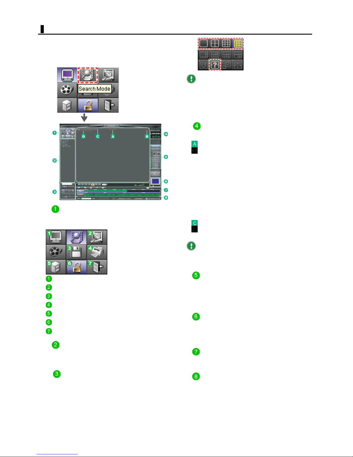
SEARCH COMPONENTS
To search and play back recorded video, click the
[SEARCH] mode button.
The screen changes to the SEARCH screen, where you can
play back recorded video from multiple cameras on a
multi-screen display.
Mode Buttons
On the SEARCH screen, the following Mode buttons are
available.
Selecting a single-screen layout initially displays
reduced video, which is 0.54 times the actual size.
The preset camera layouts you can display on the
SEARCH screen are limited to those listed in the pull-down
menu, which are single-screen, quad-screen, 9-screen,
and 16-screen layouts.
Video Display Area
Playback video is displayed here.
Each video is displayed with the following information.
Camera name
Recording mode
NOR: Normal recording
MOT: Motion recording
SEN: Sensor recording
TXT: Text recording
M/S: Simultaneous Motion/Sensor recording
M/T: Simultaneous Motion/Text recording
S/T: Simultaneous Sensor/Text recording
M/S/T: Simultaneous Motion/Sensor/Text recording
PRE: Pre-alarm recording
A: Audio recording
Recording date and time
Zoom magnification (in single-screen layout only)
LIVE button
SETTINGS button
COPY button
PRINT button
ETC button
LOG VIEWER button
LOGOUT
Displays the LIVE screen.
Displays the SETTINGS screen.
Displays the Copy screen.
Displays the Print screen.
Displays the pull-down menu.
Displays the Log Viewer screen.
Displays the Login screen.
Camera Information
Camera information for all channels is listed in a tree
format.
Screen Selection Buttons
Use these buttons to switch the screen layout.
On the SEARCH screen, the following buttons are available.
Screen Layout buttons for selecting the single-screen,
quad-screen, 9-screen, and 16-screen layouts.
Buttons to display preset camera layouts and the
[User Layout] button
If the channel has no recorded data at the playback
point, the "Digital Video Recording System" logo will be
shown.
Calendar
Select to search the recorded data or backup data and
show the calendar of the data.
Data Drive: Search the recorded data on DVR.
Backup Drive: Search the backup data.
Zoom Panel
Use this panel to perform zoom operations.
You can adjust the zoom magnification in the range of
0.54 to 1.66 times.
Search panel
Use this panel to search and play back recorded video.
Status bar
The status bar shows information such as hard disk usage
and the connection statuses of the network device or
recording media.
24
English
Page 25
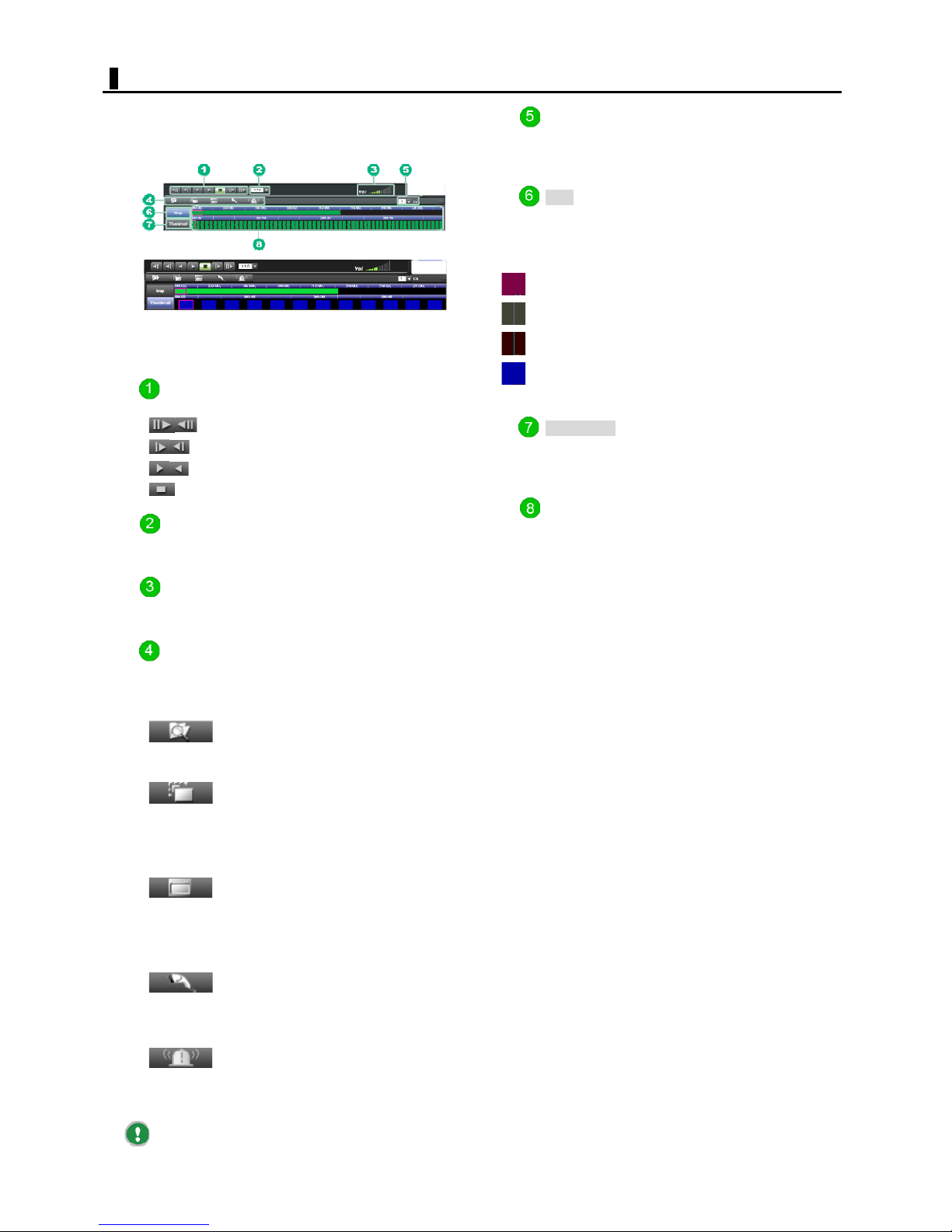
SEARCH COMPONENTS
Functions of Search panel components
Clicking Map/Thumbnail toggles the panel appearance as
shown below.
Click this to show 12 thumbnail images below the time
scale, each representing the video recorded at that time,
in an interval of 5 minutes.
Playback buttons
: Go to latest/oldest data of the day.
: Frame-forward/rewind
: Forward/reverse playback
: Stop
Playback speed indication
Shows the playback speed in six steps (?.5, 1.0, 2.0, 3.0,
4.0, and 5.0) .
Audio volume control
The audio output is made when the playback speed is x1.0
in a single-screen layout.
Channel selector (Ch)
Select the channel from which you want to play back video
in a single-screen layout.
Map button
Click this to show time bars (in hours/minutes) along the
time scale.
These time bars are colored according to the recording
mode.
Normal recording
Motion recording
Sensor recording
Text recording
Thumbnail button
Click this to show 12 thumbnail images below the time
scale, each representing the video recorded at that time,
in an interval of 5 minutes.
Time scale
The recording time information is indicated as time bars or
thumbnails.
The current playback point is indicated with a red border.
Upper scale (hours): Display range = 1 day (Scale = 1
hour to24)
Lower scale (minutes): Display range = 1 hour (Scale
= 1 minute to 60)
Search menu
Click one of the buttons in the Search menu to start the
desired search.
Detail Search button
ts up to 24 searched thumbnail images
Presen
of the video at a time.
Smart Search button
Uses the motion sensing feature of the system
to search scenes containing any motion in the
target area. You can perform this search also
on the LIVE screen.
All Channel Map button
Lists recording information on all channels in
the [All channel video map] window.
Specify the playback start point on the time bar
to play back recorded video in the selected
screen layout.
On the LIVE screen, you can playback video for
the specified channel.
POS Search button
Uses keywords to search for playback video in
text data recorded by a POS or ATM.
You can perform this search also on the LIVE
screen.
Event Search button
Uses the alarm logs listed by event to search
and play back recorded video.
You can perform this search also on the LIVE
screen.
The playback of searched video may start from
slightly before the searched point.
25
English
Page 26

TIME SEARCH
You can playback recoded video by specifying the
recording date and time.
Click the [SEARCH] mode button.
The screen changes to the SEARCH screen, which contains
a still image of the video together with the Search panel.
Select the desired Screen Layout button.
You can select single-screen, quad-screen, 9-screen, or
16-screen layout.
When you select a multiple-screen layout, you can play
back video from more than one camera simultaneously.
In the Calendar window, select the day on
which the video you want to play back was
recorded.
The beginning scene of the video recorded on the selected
day appears with map.
: Day with recorded video.
G
: Day currently selected.
G
In the Search panel, specify the point at which
you want to start play back by clicking the desired
map.
Use the upper time bars to specify the playback start point
in units of hours.
Use the lower time bars to specify the playback start point
in units of minutes.
Click the forward playback button.
Playback starts from the specified playback start point. To
perform fast-forward, pause, and other playback
operations, use the corresponding playback buttons.
26
English
Page 27
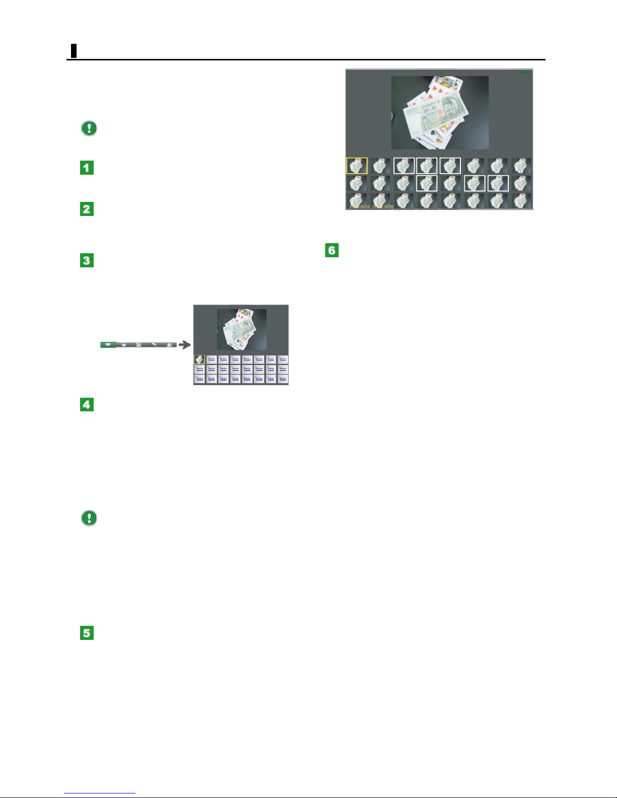
DETAIL SEARCH
You can search for the desired scenes of the video from
the displayed thumbnails.
Use this search method if you want to compare images
frame by frame, or choose the images you want to print or
copy.
Before starting a Detail search, select the channel
whose video scenes you search for.
Click the [SEARCH] mode button.
The screen changes to the SEARCH screen, which contains
a still image of the video together with the Search panel.
Select the desired video from the channel and
switch to the single-screen layout.
If you do not specify any channel, the video scenes from
Channel 1 will be searched by default.
In the [Search menu], click the [Detail Search]
button.
The Thumbnail Search screen appears, showing the first
thumbnail (still image) of the video.
For the next steps and later, refer to "Printing the Playback
Video" or "Copying Playback Video".
Click the [Detail Search] button again.
The Thumbnail Search screen closes and you return to the
normal SEARCH screen.
To show the second and later thumbnail
images...
Perform the following operation to show the second and
later thumbnail images.
Play back video continuously.
Playing back the video causes the second and later
thumbnail images to appear continuously frame by frame.
Pick up scenes one by one.
Click the time bar. Each time you click, a still thumbnail
image of the playback point appears.
The currently selected thumbnail image is shown in
a yellow rectangle, with its magnified view displayed in
the upper preview area.
If you have more than 24 thumbnail images, the
existing thumbnail images will be overwritten with later
ones from the first thumbnail.
Moreover, changing the channel being selected
during a search causes the display of the thumbnails to
reset and start newly from the first thumbnail.
To print/copy a searched image
From among the displayed thumbnail images, click the
image(s) you want to print or copy.
The selected image is now shown in a white rectangle (the
last selected image is shown in a yellow rectangle).
27
English
Page 28
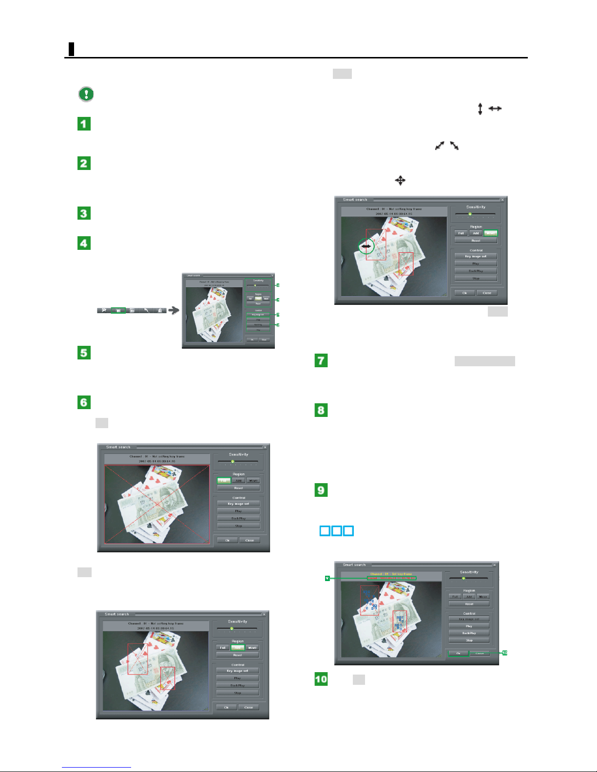
SMART SEARCH
Uses the motion sensing feature of the system to search
scenes containing any motion in the target area.
Before starting a Smart search, select the channel
whose video scenes you search for.
Click the [SEARCH] mode button.
The screen changes to the SEARCH screen, which contains
a still image of the video together with the Search panel.
Select the desired video from the channel and
switch to the single-screen layout.
If you do not specify any channel, the video scenes from
Channel 1 will be searched by default.
Start playing back the video and stop at the
point you want to start a search.
In the [Search menu], click the [Smart Search]
button.
The [Motion Search] screen appears.
In the [Sensitivity] section, use the slider to set
the sensing sensitivity.
The sensing sensitivity increases as you move the slider to
the right.
In the [Region] section, set the sensing area.
To start a Motion search by sensing the entire screen,
click Full.
To adjust the size or position of a set sensing area,
click Move and then drag as follows:
To enlarge or shrink a sensing area horizontally or
vertically, drag with the mouse pointer placed at a point
on the red rectangle, where it turns to the
To enlarge or shrink a sensing area diagonally, drag
with the mouse pointer placed at any corner of the red
rectangle, where it turns to the
To move a sensing area, drag with the mouse pointer
placed at a point near the center of the red rectangle,
where it turns to the
To cancel the sensing area setting, click Reset. This
cancels all the sensing areas currently set.
Cancelling the existing sensing area is needed if you
intend to set the sensing areas from the scratch.
In the [Control] section, click Key Image Set.
The digital video recorder is now ready for starting a
Motion search, showing an yellow "Set area frame"
message.
Click the Play/Reverse Play button to start a
search.
The digital video recorder starts a playback and searches
for scenes containing any motion in the target area.
Play: Starts a search in the forward direction.
Reverse Play: Starts a search in the reverse direction.
Stop: Stops the search.
shape.
shape.
shape.
To perform a Smart search for a specific area, click
Add and then specify the sensing area by dragging.
The selected area is now shown in a red rectangle. You
may set as many sensing areas as you want.
The digital video recorder stops playing back
the video when it finds a scene with any target
motion, showing a red "Found" message.
Portions where any motion is sensed are now shown as .
To resume the search, click the Play/Reverse Play button
again.
Click OK.
The [Smart Search] screen closes, with the searched
image displayed in the SEARCH screen.
28
English
Page 29
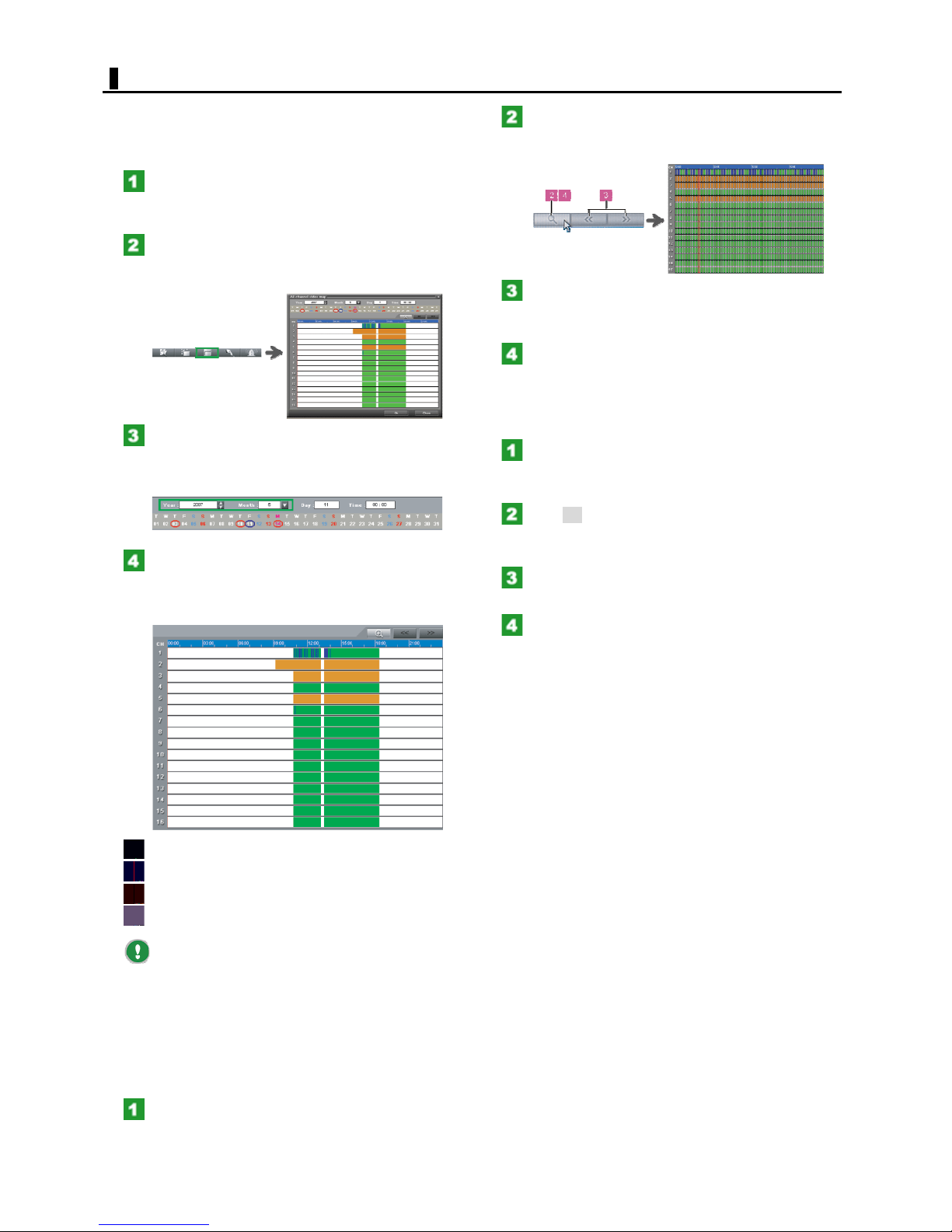
MAP SEARCH
You can list recording information on all channels in the
[All channel video map] window.
Specify the playback start point on the time bar to play
back recorded video in the selected screen layout.
Click the [SEARCH] mode button.
The screen changes to the SEARCH screen, which contains
a still image of the video together with the Search panel.
In the [Search menu], click the [All Channel
Map Search] button.
The [All channel video map] window appears.
Using the [Year] and [Month] fields, specify the
year and month in which you want to perform a
search.
The calendar for the specified month appears.
In the Calendar window, select the day on
which the video you want to search was recorded.
The search result appears as time bars for each channel.
The time scale is set to 24 hours map.
Click the magnifying glass button.
The time scale changes to 1 hour map, showing when the
recording occurred minute by minute.
Click the Previous/Next hour button.
The result for the next/previous hour is shown with the
minute time bars.
Click the magnifying glass button again.
The default time scale (graduated in hours) is restored.
Playing back video from the searched point
With the time bars (graduated in hours), move
the cursor to the point at which you want to start
playing back the video.
Click OK.
A still image representing the searched playback start
point appears in the screen layout currently selected.
Use the Screen Selection button to select the
desired screen layout for the playback video.
Click the forward playback button.
Playback starts from the specified playback start point in
the specified screen layout.
: Normal recording
: Motion recording
: Sensor recording
: Text recording
The "NOR" (Normal recording) indicator is not
shown when the normal recording is performed
simultaneously with the Motion, Sensor, or Text recording.
Showing the detailed view of the time bars
You can view the search result in more detail by showing
the time bars for a specific hour in minutes.
Drag the cursor line to the hour for which you
want to show the minute time bars.
29
English
Page 30
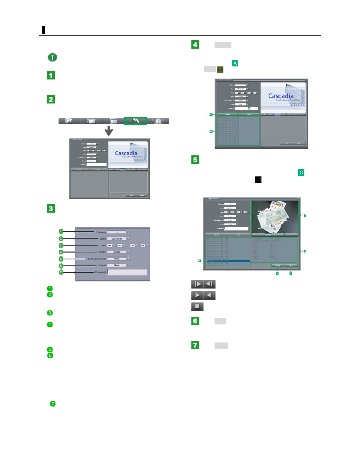
POS SEARCH
You can use keywords to search for playback video, by
searching through data recorded by a POS or ATM.
Before starting a POS search, select the channel
whose video scenes you search for.
Click the [SEARCH] mode button.
The screen changes to the SEARCH screen, which contains
a still image of the video together with the Search panel.
In the [Search menu], click the [POS Search]
button.
The [Text Search] screen appears.
Click Search.
The digital video recorder searches recorded data that
matches the specified search criteria and shows them in
the Text List area
Click Clear to clear all search results in the Text List
area.
In the Text List area, select the recorded data
you want to play back by double-clicking.
The surveillance video of the selected data
appears with its text data .
To start playing back the video, click the desired playback
buttons.
.
Enter search criteria.
To perform a Text search, you must specify 1 to 4 as
search criteria.
Camera: Camera number (1 to 16).
Date: Recording date of the video you want to search.
In the calendar that pops up, click the day on which you
want to perform a Text search.
Time: Search duration (in "hour:minute" -
"hour:minute" format).
Order: Display order of the search results in the Text
List area.
Dscend:Newer to older video.
Ascend: Older to newer video.
Text device ID: POS ID (1 to 16)
Event:
Type of the events to be searched for.
None: Searches for all text events in the specified
search duration.
True: Searches for text events including the specified
keywords.
False: Searches for text events that does not include
the specified keywords.
Keyword:
In this field, type a list of search keywords (max. 30
characters).
<Playback buttons>
: Frame-forward/rewind
: Forward/reverse playback
: Stop
Click Save.
The [Copy] screen
searched video data.
Click Close.
The [Text Search] screen closes and you return to the
state before starting the Text search.
appears, allowing you to save the
30
English
Page 31
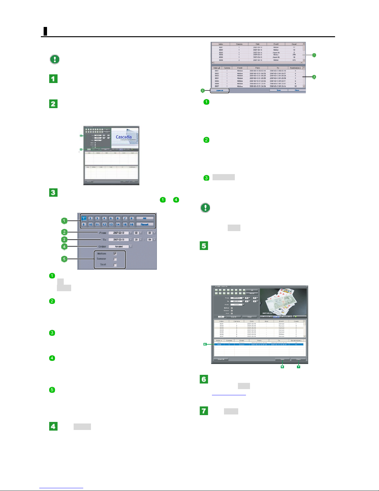
EVENT SEARCH
The Alarm Log list allows you to search and play back
recorded video.
Before starting an Event search, select the channel
whose video scenes you search for.
Click the [SEARCH] mode button.
The screen changes to the SEARCH screen, which contains
a still image of the video together with the Search panel.
In the [Search menu], click the [Event Search]
button.
The [Event Search] screen appears.
Enter search criteria.
To perform a Text search, you must specify 1 to 4 as
search criteria.
]
Total Count List
Lists the total counts of searched events by sorting in the
order of [Date], [Camera], and then [Event] columns.
You can select to display either the Daily or Hourly total
from the pull-down menu.
Details List
Lists the details of searched events.
By default, all searched logs are listed. To narrow down
the range of logs to be displayed, select the desired row in
the total-count list.
Show All
If you are viewing logs for a selected row, click this button
to display all the searched logs back again in the Details
List.
You can switch the sort order of the searched logs
between the ascending and descending orders by clicking
the header row of each column.
Click Clear to clear all the data in the Alarm Log list.
Camera number (1 to 16).
All: Selects all camera numbers.
Reset: Deselects all camera numbers.
Search start point (From)
In the calendar that pops up, click the day on which the
video scenes you want to search for were recorded and
then, from the pull-down menu, select the search duration.
Search end point (To)
In the same manner as you did in 2, set the date and time
at which you want to finish this search.
Display order of the search results in the Alarm Log
area (Order)
Dscend:Newer to older video.
Ascend: Older to newer video.
Type of the events to be searched for.
Motion:Searches for Motion recording events.
Sensor: Searches for Sensor recording events.
Text: Searches for Text recording events.
Click Search.
The digital video recorder searches recorded data that
matches the specified search criteria and shows them in
the Alarm Log list.
The Alarm Log list consists of the total-count and eventdetails list sections.
Select the recorded data you want to play back
in the Alarm Log list by double-clicking.
The video of the recorded data you selected appears.
To start playing back the video, click the desired playback
buttons. For how to play back the video, refer to the
explanation for the playback buttons on the Search panel.
In the details list, select the event you want to
save and click Save.
The [Copy] screen
searched video data.
Click Close.
The [Alarm Log Search] screen closes and you return to
the state before starting the Alarm Log search.
31
appears, allowing you to save the
English
Page 32
BACKUP SEARCH
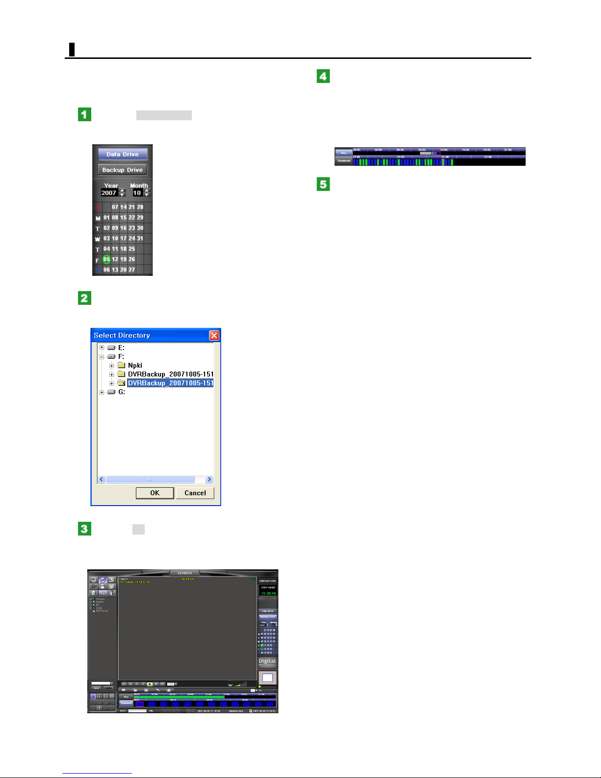
DVR supports the Data Search and Backup Search. can
playback the backup video on DVR.
Default search on the search mode is the [Data Search].
Click the Backup Drive.
Selecting the [Backup Drive] switches the search mode
from data search to backup search.
Select the backup drive and the folder.
You can select single-screen, quad-screen, 9-screen, or
16-screen layout.
In the Search panel, specify the point at which
you want to start play back by clicking the desired
map.
Use the upper time bars to specify the playback start point
in units of hours.
Use the lower time bars to specify the playback start point
in units of minutes.
Click the forward playback button.
Playback starts from the specified playback start point. To
perform fast-forward, pause, and other playback
operations,
use the corresponding playback buttons.
Click the OK.
Show the backup data on the viewing screen. The backup
data will be displayed according to the selected viewing
layout.
32
English
Page 33
SETTING COMPONENTS
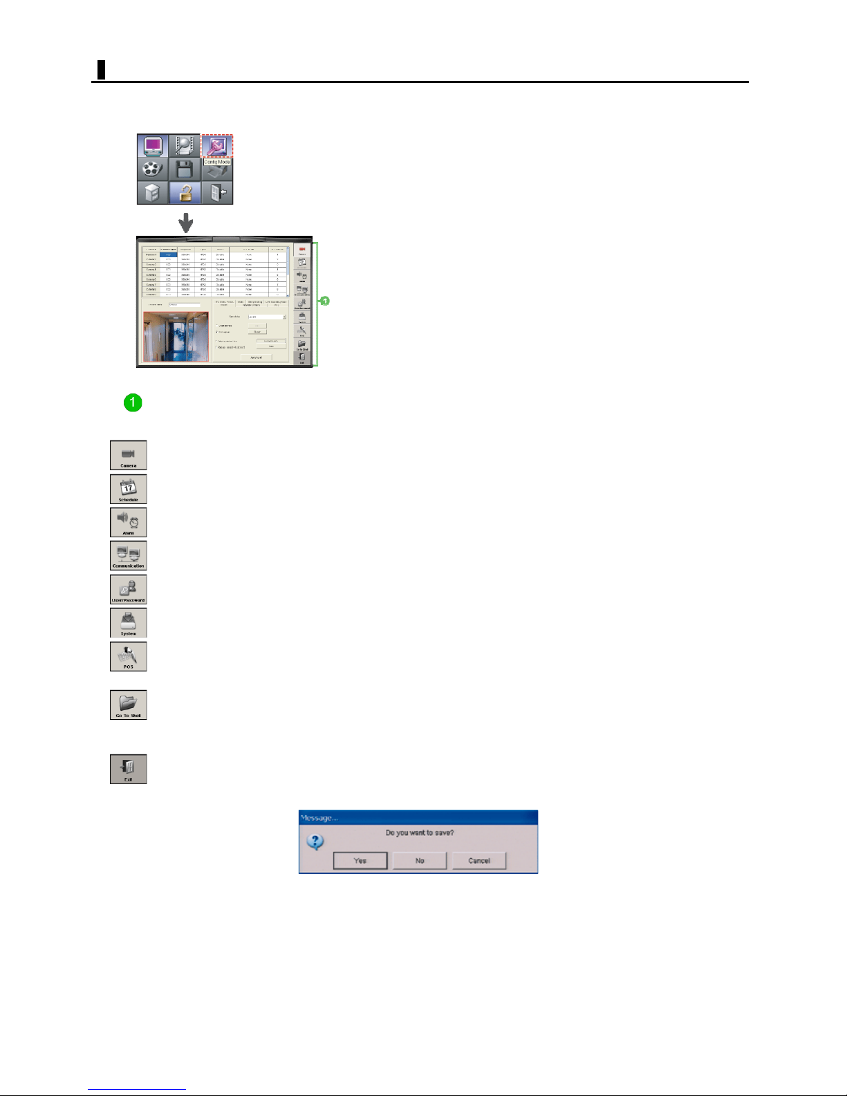
It is used to set the detailed settings of the digital video recorder.
Clicking the [CONFIG] mode button causes the CONFIGURATIONS screen to appear.
Use the setting buttons provided at the right end of the screen to access the desired settings.
Configuration buttons
Clicking each setting button displays the corresponding settings screen.
Camera Settings Allows you to set the operation conditions of each camera connected to the digital video
Schedule Settings Allows you to set the recording schedule.
Alarm Settings Allows you to configure the settings related to the alarm input/output.
Communication Settings
User/Password Settings
System Settings
Text Settings
Go to Shell
Exit
recorder.
Allows you to configure the communication conditions and other settings necessary to
tablish a network connection.
es
Allows you to register users who use this system and their operating authorities.
Only "Administrator" users can click this button.
Allows you to configure the basic system conditions, system behaviors when an event
occurs, backup conditions, and other settings.
Allows you to perform Text recording by connecting the digital video recorder to a POS or
ATM .
Allows you to exit the system and go to the Shell screen, where you can configure the system
environment.
Only "Administrator" users can click this button.
Allows you to return to the LIVE screen.
Clicking
this button opens a confirmation dialog box, asking you whether or not to save the
settings you have configured. Select Yes or No to proceed.
If you select Yes, besides the settings configured on the CONFIGURATION screen, the
screen layout, ETC menu, and [Server to Server] settings will be saved simultaneously.
33
English
Page 34
CAMERA SETTING
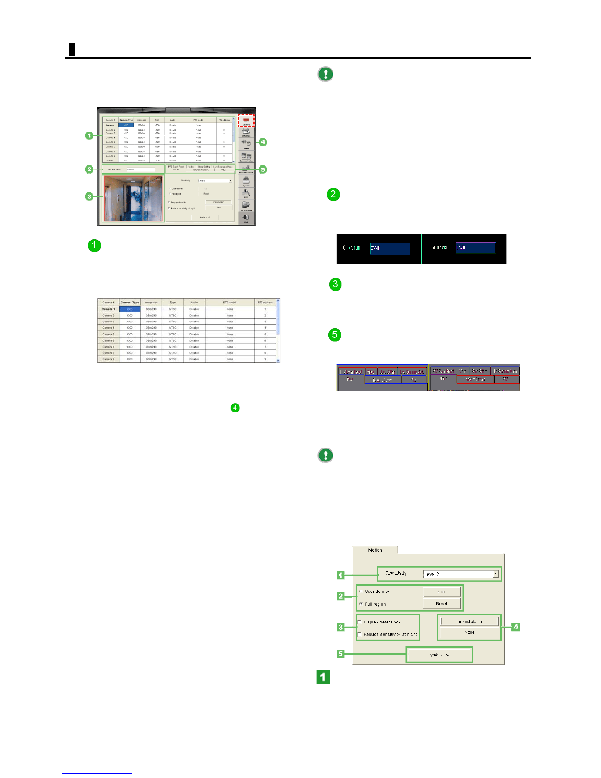
Click the [Camera] setting button to display the Camera
settings.
Here, you can set the operation conditions of each camera
connected to the digital video recorder.
Camera setting table
Clicking each header cell of the setting table invokes a
pull-down menu.
Configure the camera type, connection conditions, and
other settings for each camera.
If you set the camera type ([Camera]) to "Network"
Size: Shows each camera's size setting
automatically.
Quality: Honors each camera's quality setting,
which is not shown in the setting table, however.
Audio: Select the [Network Camera] tab, click Detail
Setup, and access [Network camera detail settings
configure the audio setting.
The video from network cameras is not output to
the MON1/MON2 (video output) terminals and the Zoom
panel.
Camera Title
If you want to change the camera title shown, type here a
new title with a length of 22 characters or less.
Default setting: CAM01 to CAM16
Preview area
Clicking a camera number in the Camera setting table
causes the video from the selected camera to appear in
the Preview area.
Detailed Setup Tabs
These seven index tabs are used to access detailed
condition settings.
] to
Camera #:
Show the camera number of the camera for which you
want to configure settings. The video from the camera
you selected appears in the Preview area .
Camera Type:
Set the camera type for each camera.
Selecting "Network" causes the line for that camera to
appear in a different color.
Setting options:
None (No camera connected)
CCD (Normal camera)
Network (Network camera)
Image Size:
Set the image size for the bundle of channels as follows:
MP 7016: CH1 to 4, CH5 to 8, CH9 to 12,or CH13 to 16.
MP 6016: CH1 to 8
MP 5016: CH1 to 16
Setting options:
PAL: F360x288, 720x288, and 720x576
NTSC: Setting options: 360x240, 720x240, and 720x480
Type:
Set the video signal type (NTSC, PAL)
Audio:
Turn ON/OFF audio recording for each camera.
Configuring the motion sensor (Motion)
Configure the motion sensor feature that senses any
motion in the target.
In the Preview area, portions where any motion is
sensed under the configured conditions will be indicated
by blue rectangles.
These rectangles are shown based on the sensing
sensitivity and sensing area settings currently stored in the
system.
If you have changed any of these sensing
conditions, click the [Exit] setting button to save the
settings you have configured.
PTZ Model:
Set the PTZ operation protocol for each camera.
PTZ Address:
Set the PTZ operation address for each camera (1 to 127).
In the [Sensitivity] setting, select the sensing
sensitivity from the pull-down menu.
The detecting sensitivity can be set in 9levels (Level 1~ 9).
Higher the sensitivity level, lower the sensing sensitivity.
34
English
Page 35
CAMERA SETTING
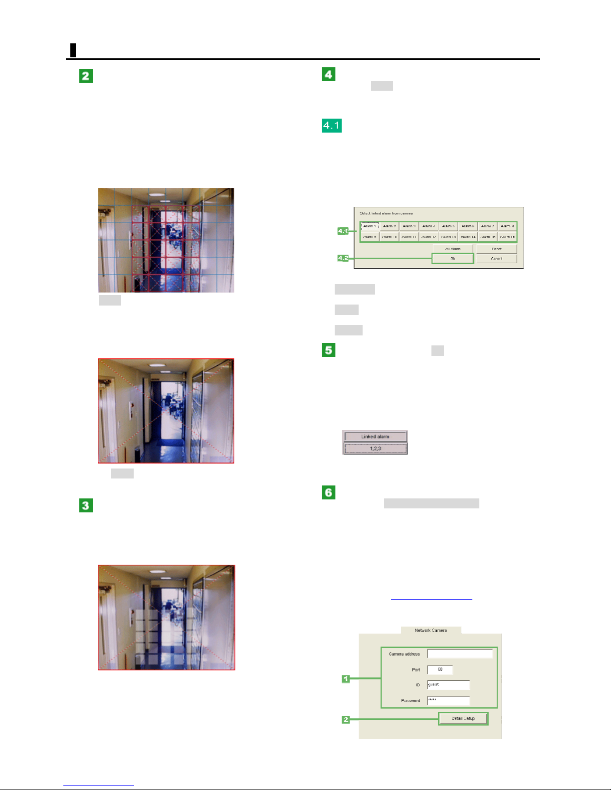
Using the radio buttons, specify whether to
define the sensing area by yourself.
When [User defined] is selected:
The [Add] button becomes selectable, allowing you to
define the sensing area as desired.
In the preview area, click in the grid cell where you want
to enable sensing.
Each time you click, the color of the selected grid cell
toggles between red and blue to indicate that sensing is
enable or disabled, respectively.
Click Reset to discard all sensing area settings.
When [Full region] is selected:
The whole screen is set as the sensing area.
The whole preview area is enclosed with a red border to
indicate that full-region sensing is enabled.
In the [Linked alarm] section, click the button
(labeled as None by default).
The [Select linked alarm from camera] setting dialog box
appears.
Click the Alarm OUT number of each terminal
that outputs an alarm signal when a motion is
sensed.
Clicking an Alarm OUT number turns On the alarm output
from the corresponding terminal. You can turn On the
alarm output for more than one terminal.
Click the terminal number again to turn Off the alarm
output.
<Other buttons>
All Alarm: Turns On the alarm output for all Alarm
OUT numbers.
Reset: Turns Off the alarm output for all Alarm OUT
numbers.
Cancel: Cancels all settings and closes the dialog box.
When finished, click OK.
The Motion setting dialog box closes. On the [Motion] tab,
the button in [Linked alarm] setting now shows the
settings you have configured ("None", Alarm OUT Nos. (1
to 16), or "All").
Clicking Reset switches the screen to the [User defined]
mode.
Select the display detect box, reduce
sensitivity at night.
When [Display detect box] is selected:
Show the motion detcting status in grey rectangle on the
preview screen.
When [Reduce sensitivity at night] is selected:
Reduce the motion detecting sensitivity at night. It helps
filtering camera noise when motion is detected.
<Display example when Alarm OUT Nos. 1, 2, and 3 are
turned ON>
In the [Linked alarm] setting, click the button again to
return to the setting dialog box.
To configure all cameras to have the same
settings, Click All camera config copy.
The system applies the settings configured on the
[Motion] tab to all cameras.
(The settings, however, are not applied to network
cameras.)
Configuring network cameras (Network Camera)
For each camera for which you set the camera type to
"Network" in the Camera setting table
setting), configure the settings necessary to establish a
network connection.
(in the [Camera]
35
English
Page 36
CAMERA SETTING
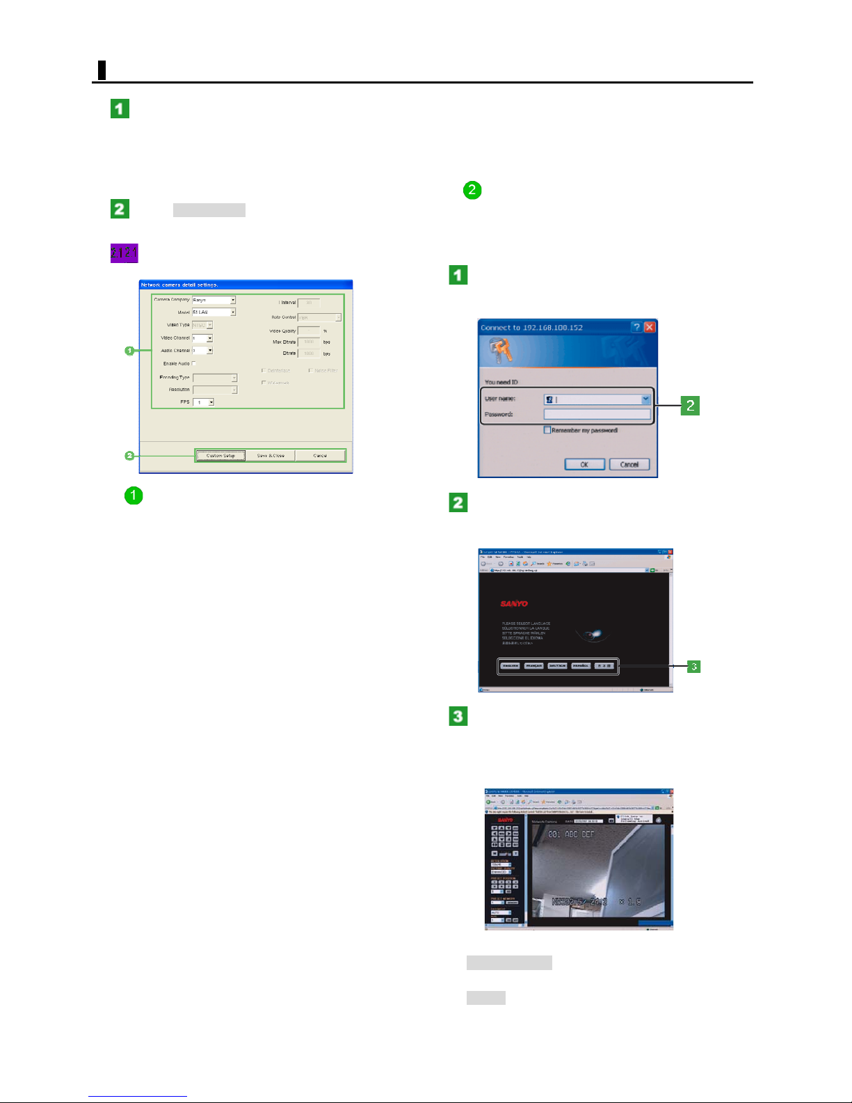
Specify the address and other information on
the camera.
"Camera Address" (IP address or Domain Name)
Port (Default setting: 80)
User ID (Default setting: guest)
Password (Default setting: guest)
Click Detail Setup.
The [Network camera detail settings] dialog box opens.
Configure the detailed settings of the
camera.
Noise Filter:
Select this check box to enable noise filtering.
Watermark:
this check box to enable water marking to prevent
Select
interpolation.
Custom Setup
You can set up your camera using the built-in Web
browser.
The below instruction is the example of sanyo's network
camera setting.
Click [Custom Setup].
The Web browser starts, presenting a dialog box for user
authentication.
Network camera detailed settings
The displayed items vary depending on the camera model.
Camera Company:
Select the manufacturer of the camera.
Model:
Select the model of the camera.
Video Type:
Select the video type (NTSC or PAL).
Video Channel:
Select the channel that transmits video signals.
Audio Channel:
Select the channel that transmits audio signals.
Audio:
Select this check box to enable audio recording.
Encoding Type:
The camera's Codec setting (MJPEG, MPEG1, MPEG2,
MSMPEG 4 V1, or DIVX) is shown.
Resolution:
The camera's resolution setting is shown.
FPS:
Select the frame rate.
Interval:
The camera's I frame interval setting is shown.
For example, if the [I Internal] is "30", one I frame will be
inserted every 30 P frames.
Rate Control:
The camera's recording method setting (CBR (Constant Bit
Rate) or VBR (Variable Bit Rate)) is shown.
Video Quality:
The video quality is not shown.
Max Bitrate:
The camera's maximum VBR (Variable Bit Rate) setting is
shown.
Bitrate:
The camera's maximum CBR (Constant Bit Rate) setting is
shown.
Deinterlace:
Select this check box to enable deinterlacing.
Type an "Administrator" user name and
password and click [OK].
e language selection screen appears.
Th
Click the button corresponding to the language
you want to use.
The camera setup screen appears.
For the setup procedure, refer to the instruction manual
that comes with your camera.
<Other buttons>
Save & Close: Saves the configured settings and
closes the dialog box.
Cancel: Cancels the configured settings and closes the
dialog box.
36
English
Page 37
CAMERA SETTING
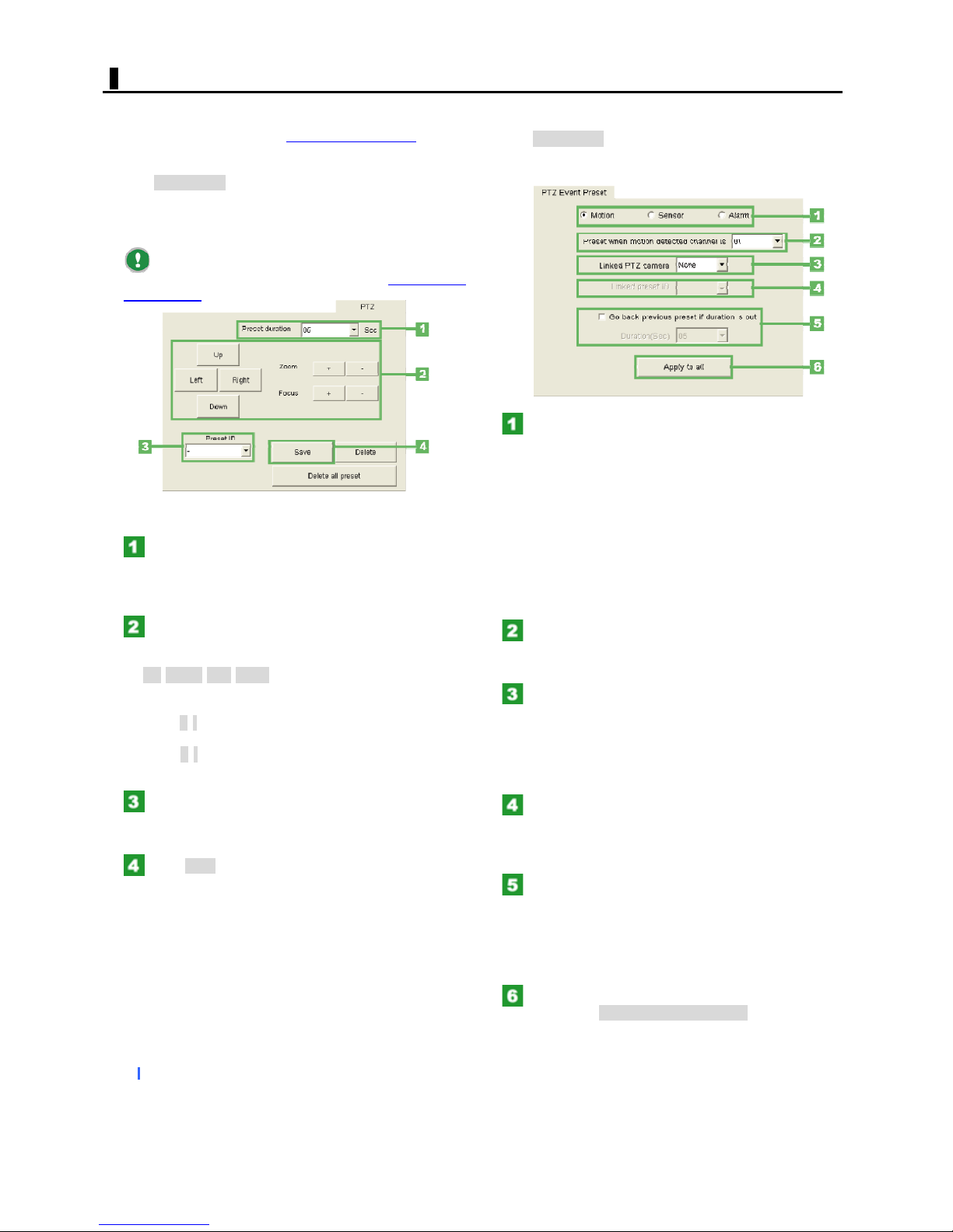
Configuring PTZ camera positions (PTZ Preset)
Setting a protocol in the Camera setting table (in the
[Protocol] column) allows you to configure the operation
settings of a PTZ camera.
Click PTZ Preset.
In the dialog box that appears, register camera states
such as the current orientation and zoom magnification as
preset positions. You can register up to 12 preset positions.
The registration and deletion of these preset
positions may also be performed from the PTZ Camera
Control panel.
Registering preset positions
In the [Preset duration] setting, select the
monitoring time (04 to 60 seconds) at the preset
position from the pull-down menu.
The set preset duration will be applied during a preset run.
Button to set PTZ camera options (PTZ Option)
Click PTZ Option.
You can orient the camera to a preset position, linked to
the occurrence of an event.
Using the following radio buttons, specify the
type of event to which you want to link a preset
position.
Setting options:
Motion:
Motion event that occurs when any motion is sensed in
the target by the motion sensor.
Sensor:
Sensor event that occurs when an external alarm signal is
input.
Alarm OUT:
Alarm OUT event that occurs when alarm output is made.
Set the orientation, zoom, and focus of the
camera you want to register using the following
buttons.
Up/Down/Left/Right:
Adjusts the orientation of the camera in the
up/down/left/right direction.
Zoom +/-:
Adjusts the zoom magnification.
Focus +/-:
Use these buttons to adjust the focus.
In the [Preset ID] setting, select a registration
number (1 to 12) for the preset position from the
pull-down menu.
Click Save.
The current position is registered as a preset position with
the selected preset number.
By following the same procedure (Steps 1 to 4), you can
register up to 12 preset positions.
Deleting preset positions
To delete preset positions one by one:
Select the preset number you want to delete in the [Preset
ID] setting and Click Delete. The registered preset position
has been deleted.
To delete all preset positions:
Click Delete all preset. All the preset positions currently
registered have been deleted.
Select the channel for which you want to link
the event type to a preset position from the pulldown menu.
Select the camera you want to orient to a
preset position, linked to the occurrence of an
event of the set type.
The pull-down menu lists each camera number for which a
protocol is set in the [Protocol column] in the Camera
setting table.
Select the preset position to which you want
to orient the camera.
The pull down menu shows the preset ID you registered
for the camera in Step 3.
To enable auto return feature, select the
check box and, in [Duration(Sec)] setting, select
the return duration.
When the selected return duration expires, the camera
automatically returns to the previous preset position.
Setting options: 05, 10, 20, 30, 40, 50, 60 Sec
To configure all cameras to have the same
settings, Click All camera config copy.
The system applies the settings configured on this screen
to all cameras.
37
English
Page 38
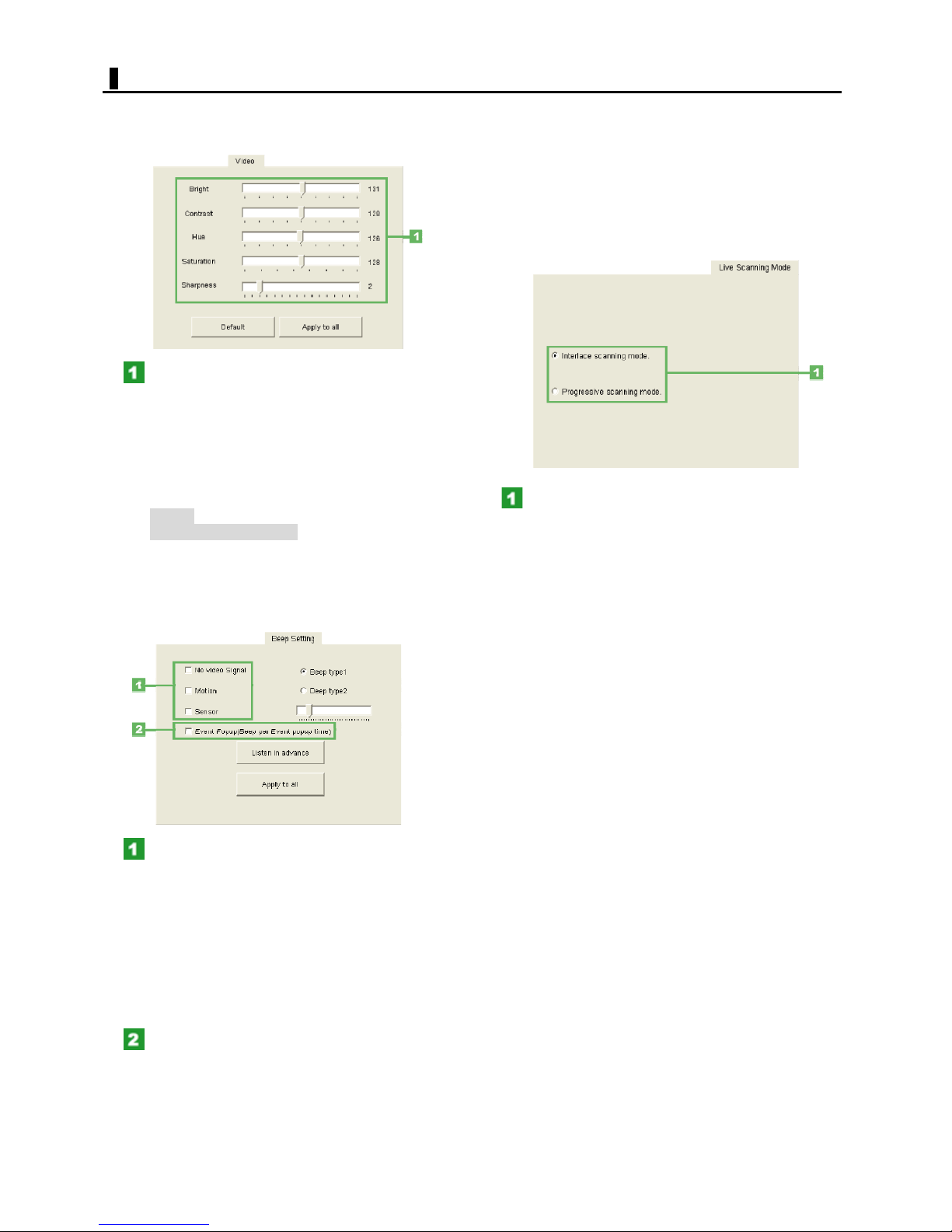
CAMERA SETTING
Configuring the video quality (Video Quality)
Configure the quality of the video displayed on the monitor.
Adjust the video quality using the slider bars.
Note that this adjustment is possible when the [Camera]
setting in the Camera setting table is set to "CCD".
Brightness: Brightness of the video
Contrast: Contrast of the video
Hue: Hue of the video
Saturation: Saturation of the video
<Other buttons>
Default: Resets the settings on the tab to the defaults.
All camera config copy: Applies the settings on the
tab to all cameras.
Configuring the alarm beep (Beep Setting)
Configure the alarm beep that will be output if an event
occurs.
<Other buttons>
Beep type: Select a beep sound to work with alarm..
Listen in advance: Listen the selected beep sound in
advance.
All camera config copy: Applies the settings on the
tab to all cameras.
Configuring the video quality (Video Quality)
Configure the quality of the video displayed on the monitor.
Using
the following radio buttons, select the
scanning mode of live video.
Interlace scanning mode:
Fast but does not support the panning view.
Progressive scanning mode:
More dense and supports the panning view.
Select the check box for the event type for
which you want to enable the alarm beep.
The alarm beep will sound if an event of the selected type
occurs. You can select more than one event type.
Setting options:
No Video Signal: Type of event that occurs when
the video signal is interrupted
Motion: Type of event that occurs when any motion
is sensed in the target by the motion sensor
Sensor: Type of event that occurs when an external
alarm signal is input
Select the Event Popup check box to enable
the Event Popup feature.
When the Event Popup feature is enabled, the system
displays relevant event video in the single-screen mode
whenever an event occurs and sounds an alarm beep.
38
English
Page 39
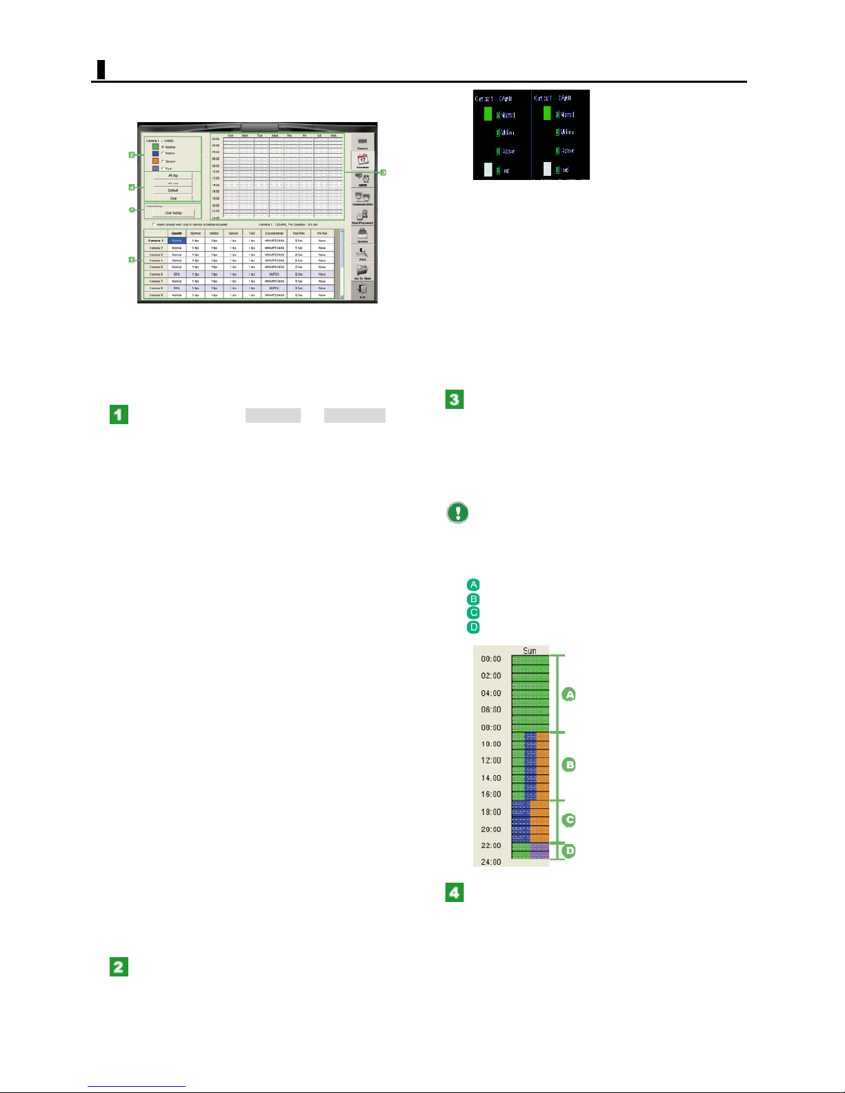
SCHEDULE SETTING
Click the [Schedule] setting button to display the recording
schedule settings.
Setting a recording schedule
You can configure a recording schedule in the following
steps:
Configuring a recording schedule allows you to
automatically record video as you planned.
Click the camera (Camera 1 to Camera 16) for
which you want to configure a recording schedule.
You can set the recording schedule values of the selected
camera.
Quality:
Set the camera quality for each camera.
Setting options: Basic, Normal, Enhanced, Fine, and Super
fine
Normal:
Set the recording rate used in Normal recording for each
camera.
The recording rates shown in the pull-down menu depend
on the [Size] setting. (This is also true for the recording
modes described below.)
Motion:
Set the recording rate used in Motion recording for each
camera.
Sensor:
Set the recording rate used in Alarm IN recording for each
camera.
Text:
Set the recording rate used in Text recording for each
camera.
Encode mode:
Set the the encoding format.(H/W MPEG4 or H/W
MPEG4(N))
Post Rec:
Set the duration of Motion, Sensor, and Text recordings for
each camera (1 Sec to 5 Min).
Pre Rec:
Set the operation conditions in Pre-alarm recording for
each camera
Setting options:
None (No Pre-alarm recording)
Short (Short Pre-alarm recording time)
Medium (Standard Pre-alarm recording time)
Long (Long Pre-alarm recording time)
Select the check box for the recording mode
you want to set.
Now, you can configure a recording schedule. You can
select more than one recording mode.
Normal:
Records video continuously during the scheduled time
period.
Motion:
Records video whenever a motion is sensed in the target
by the motion sensor.
Sensor:
Records video whenever an alarm signal is input from an
external sensor.
Text:
Records video whenever a keyword match is found in the
text, if connected to a text input device such as POS or
ATM.
In the Schedule setting area, drag on the time
bar for the desired day of the week to set a
recording schedule.
For each day (of the week), you can set the recording
time period in increments of 15 minutes.
As you drag, the time bars are filled with a color assigned
to the recording mode you selected in Step 2.
If you drag again over a time period in which you
already set a schedule, the time bar will be overwritten to
update the schedule.
<Example of setting a schedule on Sunday>
00:00 to 08:00: Normal recording
08:00 to 16:00: Normal/Motion/Alarm IN recording
16:00 to 22:00: Motion/Alarm IN recording
22:00 to 24:00: Normal/Text recording
Follow the same procedure (Steps 2 to 3) to
set a recording schedule for each day of the week.
The schedule you set in the lowermost [Holiday] area
applies to the holidays you defined in the next "Holiday
setting" section.
39
English
Page 40
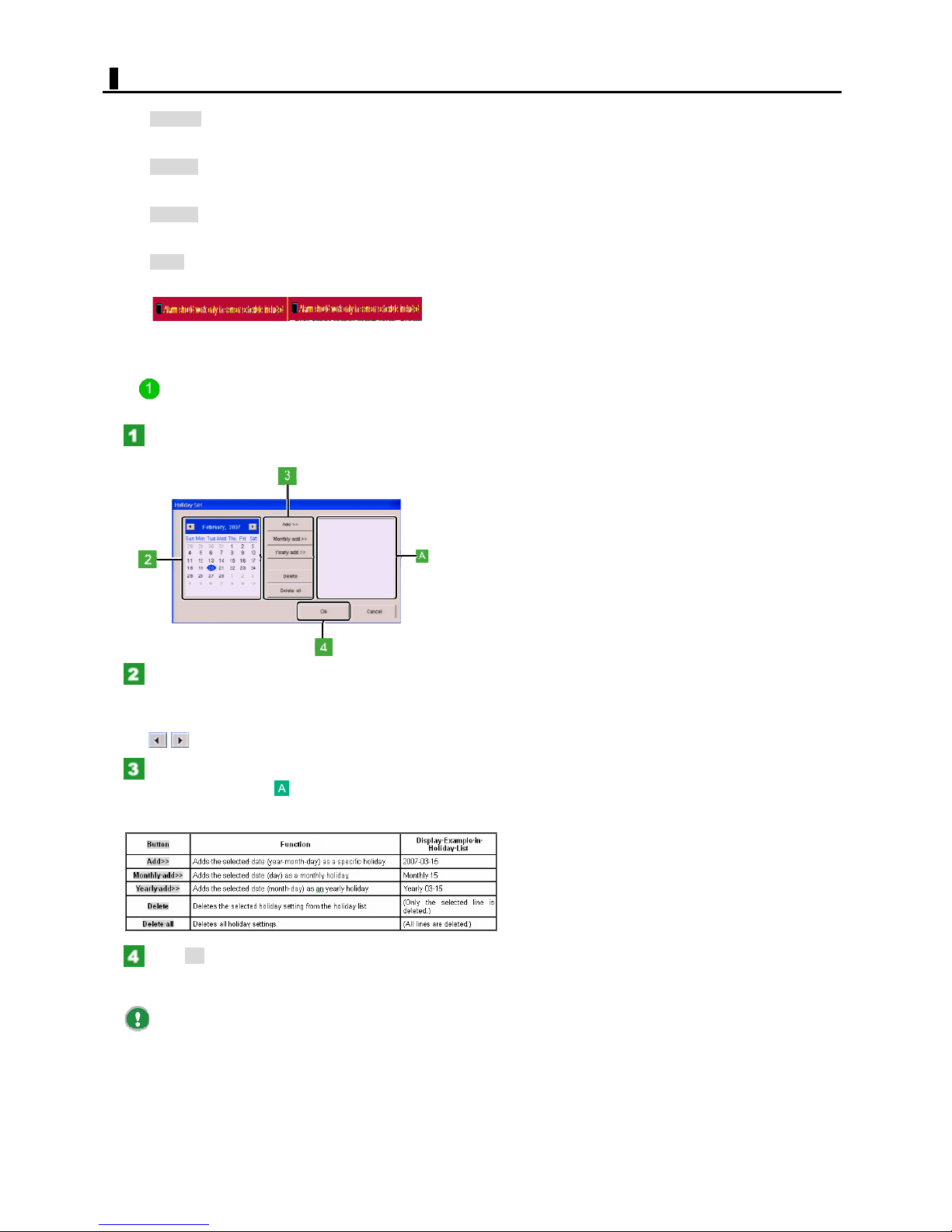
SCHEDULE SETTING
<Other buttons>
All days:
Applies the set recording schedule to all days of the week.
To cancel, click the button again.
All cam:
Applies the set recording schedule to all cameras.
To cancel, click the button again.
Default:
Sets Normal recording for all time periods in each day of
the week.
Clear:
Clears the set recording schedule.
Set the alarm to go off when only sensor schedule is set.
Setting holidays
You can define specific, monthly, or yearly holidays.
Click User holiday.
The [Holiday Set] screen appears.
On the calendar, select the date on which you
want to set a holiday by clicking.
The selected date is highlighted.
To display the calendar for the previous/next month, use
the button.
Use the following buttons to add the selected
date to the holiday list .
Use an appropriate button depending on whether you set
a specific, monthly, or yearly holiday.
Click OK.
The defined holiday settings have been saved. The dialog
box closes.
Clicking Cancel cancels the holiday settings and
closes the dialog box.
40
English
Page 41
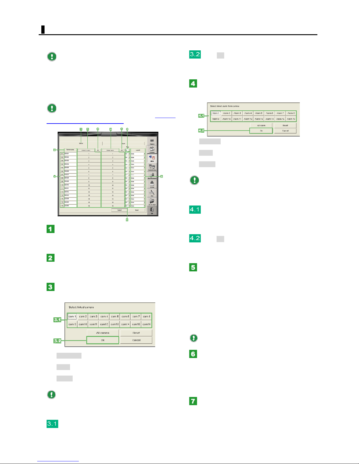
ALARM/SENSOR SETTING
Click the [Alarm] setting button to display the Alarm
settings.
This links the camera number to sensor. You can select
more than one camera number.
Each Sensor/Alarm OUT number A shown on this
screen represents the corresponding sensor/alarm output
terminal located on the rear panel of the digital video
recorder.
Configuring the alarm inputs
On this screen, configure the camera and alarm OUT
numbers linked to sensor.
To record video in conjunction with sensors, in
addition to this setting, you need to configure a recording
schedule (in the Schedule settings).
Click the [Sensor] tab.
The Sensor settings appears.
For each sensor number, follow the next and later setting
steps.
In the [Sensor name] field, type a name for the
alarm input.
To change the default name, type a new name with a
length of 22 characters or less.
Click the [Linked Camera] button.
The [Select linked camera] setting dialog box appears.
Click OK.
The dialog box closes. On the [Sensor] tab, the button
next to the [Linked Camera] button now shows the setting
("None", camera No., or "All").
Click the [Linked Alarm OUT] button.
The [Select linked alarm from camera] setting dialog box
appears.
All Alarm:
Selects all alarm OUT numbers.
Reset:
Deselects all alarm OUT numbers.
Cancel:
Cancels the settings and closes the dialog box.
To apply the same setting to all sensor numbers,
click the AllbuttonC next to the [Linked Alarm OUT] button.
Then, the common setting dialog box opens, where you
can apply common settings to all sensor numbers.
Click the alarm OUT number you want to link
to alarm input.
This links the camera number to alarm input. You can
select more than one camera number.
Click OK.
The dialog box closes. On the [Sensor] tab, the button
next to the [Linked Alarm OUT] button now shows the
setting ("None", alarm OUT No., or "All").
Under [Type], click the down-arrow button for
the desired alarm IN number and, from the pulldown menu, select the polarity of the alarm input
signal.
Setting options:
NO (Normal Open):
The terminal is normally open and a signal is output if
closed.
NC (Normal Close):
The terminal is normally closed and a signal is output if
opened.
All camera:
Selects all camera numbers.
Reset:
Deselects all camera numbers.
Cancel:
Cancels the settings and closes the dialog box.
To apply the same setting to all sensor numbers,
click the All button B next to the [Linked Camera] button.
Then, the common setting dialog box opens, where you
can apply common settings to all sensor numbers.
Click the camera number you want to link to
alarm input.
To apply the same setting to all sensor numbers,
under [Type], select "All" D from the pull-down menu.
To switch the camera layout on the monitor
screen in conjunction with alarm inputs, under
[Layout], click the down-arrow button for the
desired sensor number to open the pull-down
menu.
Then, select the desired layout name from the listed
preset names.
Follow the same procedure (Steps 2 to 10) to
configure settings for all sensor numbers.
41
English
Page 42
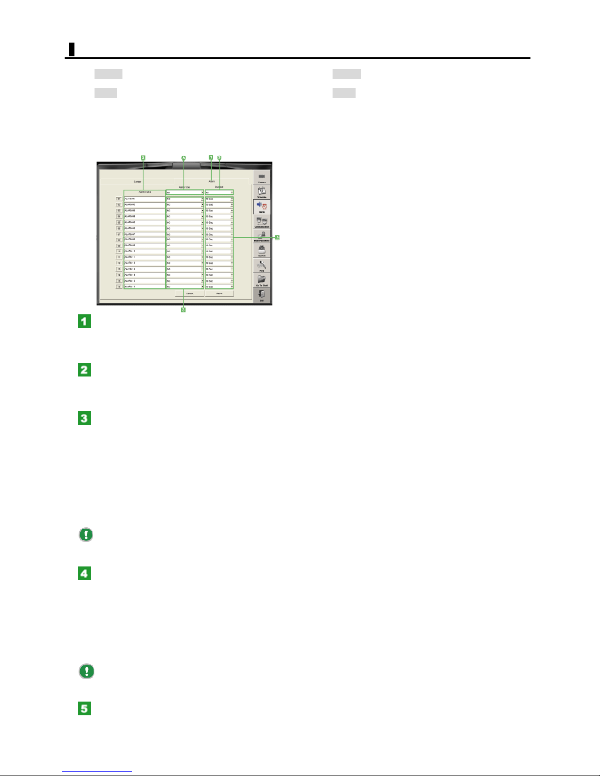
ALARM/SENSOR SETTING
<Other buttons>
Default: Resets the all settings on the tab to the
defaults.
Reset:Cancels all settings on the tab and restores the
previous conditions.
Configuring the alarm outputs
Configure the alarm output settings on the [Alarm OUT]
tab.
Click the [Alarm OUT] tab.
The alarm OUT settings appears.
For each alarm OUT number, follow the setting steps
below.
<Other buttons>
Default: Resets the all settings on the tab to the
defaults.
Reset: Cancels all settings on the tab and restores
the
previous conditions.
In the [Alarm OUT name] field, type a name for
the alarm output.
To change the default name, type a new name with a
length of 22 characters or less.
Under [Type], click the down-arrow button for
the desired alarm OUT number and, from the pulldown menu, select the polarity of the alarm output
signal.
Setting options:
NO (Normal Open):
The terminal is normally open and a signal is output if
closed.
NC (Normal Close):
The terminal is normally closed and a signal is output if
opened.
To apply the same setting to all alarm OUT
numbers, under [Type], select "All" A from the pull-down
menu.
Under [Duration], click the down-arrow button
for the desired alarm OUT number and, from the
pull-down menu, select the duration of the alarm
output signal.
Setting options:
1 TIME: Alarm signal is output once.
5 Sec to 10 Min: Specify the alarm output time as a
numeric value.
Continue: Alarm output continues until stopped.
To apply the same setting to all alarm OUT
numbers, under [Duration], select "All" B from the pulldown menu.
Follow the same procedure (Steps 2 to 4) to
configure settings for all alarm OUT numbers.
42
English
Page 43
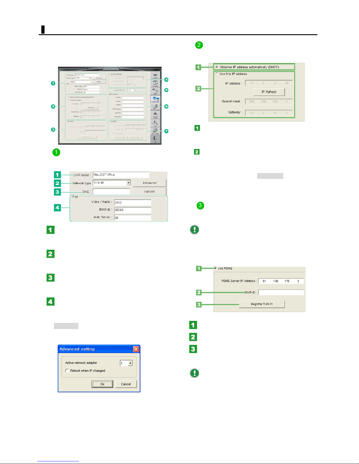
COMMUNICATION
Click the [Communication] setting button to display the
Communication settings.
Allows you to configure the communication conditions and
other settings necessary to establish a network connection.
Configuring the TCP/IP settings
Using the following radio buttons, select how you want to
set the TCP/IP address.
Obtain an IP address automatically (DHCP)
Select this to use DHCP to obtain an IP address
automatically.
Configuring the basic settings
Enter the basic information on this digital video recorder.
In the [DVR name] field, type the name of the
digital video recorder.
Provide a name of 22 characters or less.
In the [Network type] setting, check the network
protocol.
By default, this is set to "TCP/IP".
In the [DNS] field, type the domain name or IP
address of the DNS server.
Clicking Default sets the default values.
In the [Port] field, type the port number.
Provide a port number of 5 characters or less.
<Other buttons>
Advanced:
Select the network adapter ID when external modem or
multi network cards are used.
Use this IP address
Select this to specify an IP address manually. You need to
specify the following information.
IP address
To renew the IP address, Click IP Refresh.
Subnet mask
Gateway
Configuring the PDNS
To use PDNS service provided with DVR, perform the
following PDNS server setting.
By using the PDNS service, you can automatically
access and connect to your digital video recorder from the
remote connection S/W like client, CTMS by simply
entering the domain name registered with the PDNS server.
There is no need to enter the IP address of the digital
video recorder.
Select the [Use PDNS] check box.
In the [DVR ID] field, type the domain name.
Click [Register DVR ID].
A message dialog box appears, saying that the setting has
been completed.
[PDNS Server IP Address] is provided with DVR as
default. If you want to use your own PDNS server, input
your own PDNS server IP address.
43
English
Page 44
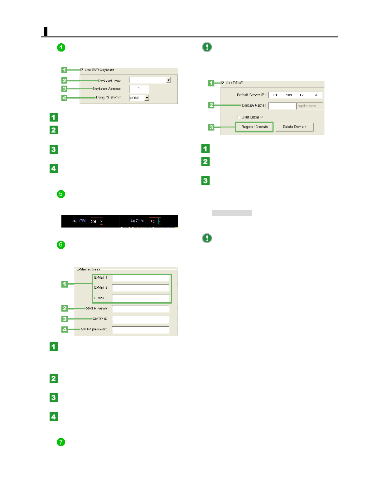
COMMUNICATION
Configuring the system controller
To connect a system controller to the digital video recorder,
you need to enter necessary information.
Select the [Use DVR Keyboard] check box.
In the [Keyboard Type], select the system
controller type from the pull-down menu.
In the [Keyboard Address] field, input the
address of keyboard address.
In the [Using COM Port] setting, select the COM
port connected to system controller.
Configuring the PTZ Port
To connect a PTZ camera to the digital video recorder, you
need to select the port of RS232-C.
By using the DDNS service, you can automatically
access and connect to your digital video recorder from
Internet Explorer by simply entering the domain name
registered with the DDNS server. There is no need to enter
the IP address of the digital video recorder.
Select the [Use DDNS] check box.
In the [Domain Name] field, type the domain
name.
Click [Register Domain].
A message dialog box appears, saying that the setting has
been completed.
<Other buttons>
Delete Domain: Delete the selected domain name
from DDNS Server.
Configuring the E-mail
To send the alarm-notification E-mail, follow the steps
below.
In each [E-Mail] field, type the address to
which you want to send an E-mail if an alarm
occurs.
You can enter up to three E-mail addresses.
In the [SMTP server] field, type the domain
name or IP address of the SMTP server.
In the [SMTP ID] field, type an authentication
ID as needed.
In the [SMTP PASSWORD] field, type an
authentication password as needed.
Normally, the [User Local IP] check box is not used.
Leave the check box deselected. Select [User Local IP]
check box when you connect to DVR using with remote
connection S/W in local network like LAN.
[DDNS Server IP Address] is provided with DVR as
default. If you want to use your own DDNS server, input
your own DDNS server IP address.
Configuring the DDNS
To use DDNS (Dynamic DNS) service, perform the
following DDNS server setting.
44
English
Page 45
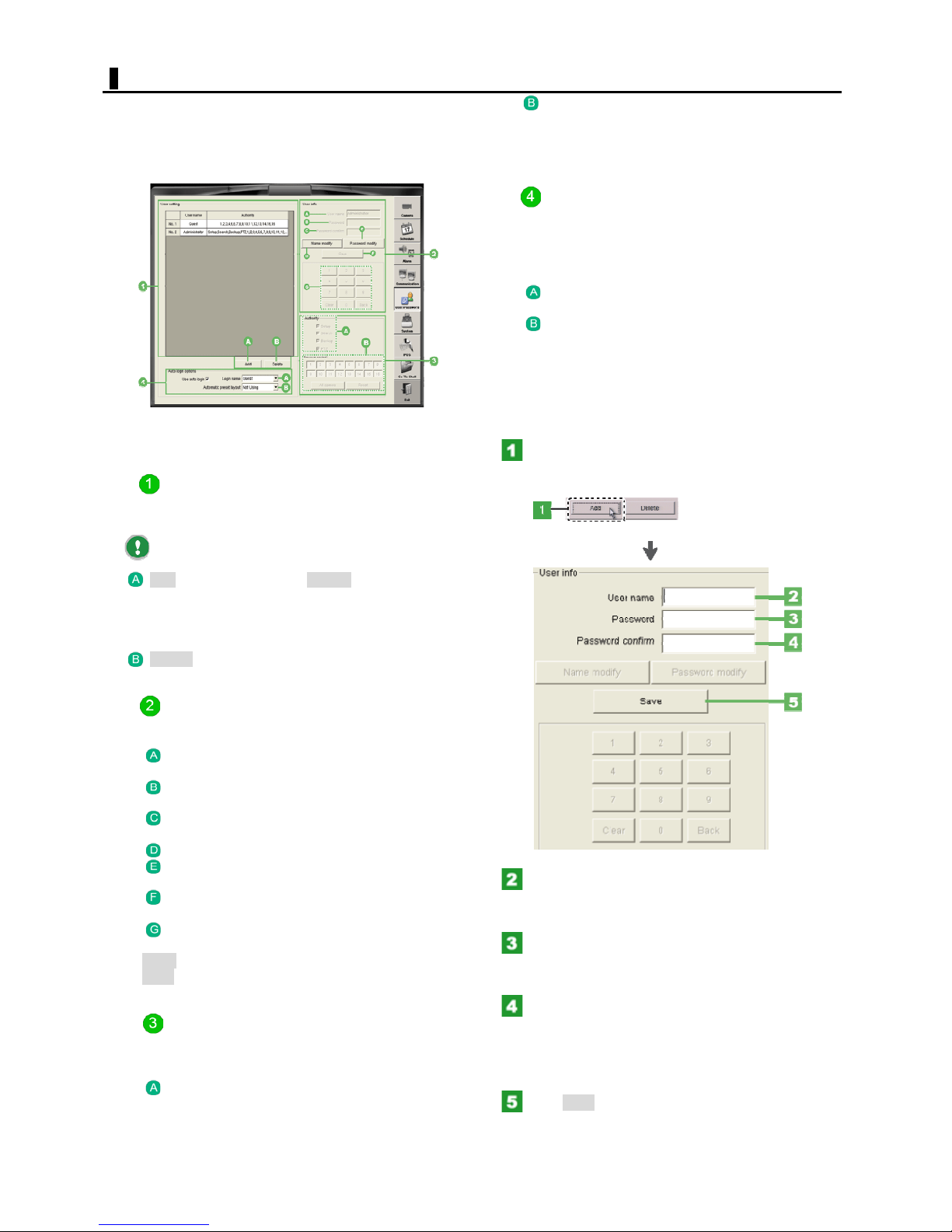
USER/PASSWORD
Click the [User/Password] setting button to display the
User/Password settings.
On this screen, register users who use this system and
their operating authorities.
Only "Administrator" users can perform this setting.
User/Password settings screen components and
their functions
User list (User Setting)
The name and operating authorities of each registered
user are listed.
Camera control
Specify the camera number of the camera for which you
want to grant the user the operating authority on the LIVE
screen.
Auto login setting (Auto login options)
Use the Auto Login feature to allow the user to
automatically log into the system when the system starts
up, without prompting for password entry.
To enable this feature, select the [Use auto login] check
box and configure the following settings.
User ID:
Select the login user name.
Automatic preset layout:
To allow the user to use preset camera layouts on the first
screen after login, select one of the preset names from
the pull-down menu
Registering a new user
Click Add.
Now, you can configure the settings in the [User info]
section.
By default, "Guest" and "Administrator" are listed.
Add: Adds a new user./Cancel: Cancels unsaved
settings.
Clicking the [Add] button changes the button label to
[Cancel].
Delete: Deletes the selected user.
User information input area (User Info)
Type the user name and password.
User Name: Type (or view) the name of the
user.
Password/New password: Type the
password for the user.
Password confirm: Type the password for
confirmation.
Name modify: You can modify the user name.
Password modify: Click this to switch the
[Password] box for password modification.
Save: Click this to save the user name and
password and register the user to the user list.
Numeric keypad: Use these buttons for
password entry.
Clear: Clears all characters in the input field.
Back: Clears the last character in the input field.
In the [User Name] field, type the name of the
user.
Provide a user name of 20 characters or less.
In the [Password] field, type the password for
the user using the numeric keypad.
Provide a user name of 20 characters or less.
Operating authority setting (Authority)
Set the operating authorities of the user you are
registering.
Authority
Select the check box for each operating authority you
want to grant to the user.
In the [Password confirm] field, type the
password for confirmation using the numeric
keypad.
For confirmation, re-enter the password you entered in
Step 3.
Click Save.
The user name and password have been registered for the
user. Now, in the user list, the user name and operating
authorities of the user are shown.
45
English
Page 46
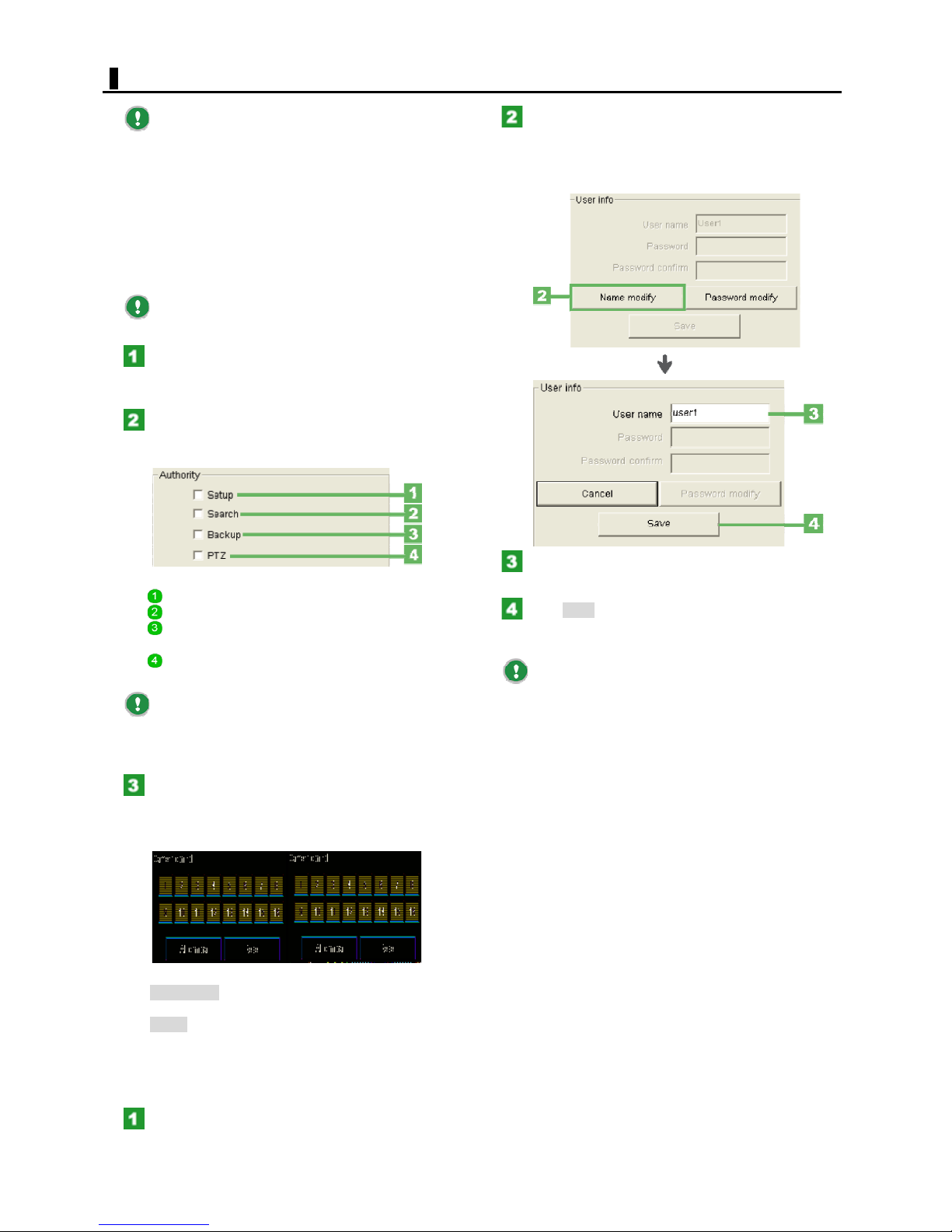
USER/PASSWORD
When you add a new user, the user is registered as
a monitoring user with the operating authorities for all
cameras (Camera controls 1 to 16 are selected). Change
the operation authorities as needed.
Configuring the operating authorities
By following the steps below, you can change the
operating authorities of registered users.
The changed operating authorities are shown real-time in
the user list.
You cannot change the operating authorities of
"Administrator".
In the user list (in the [User Setting] section),
click the user whose operating authorities you
want to change.
In the [Authority] section, select the check box
for each operating authority you want to grant the
user.
Setup: Operation on the SETTINGS screen
Search: Operation on the SEARCH screen
Backup: Operation on the BACKUP screen
manually
PTZ/Controller: Remote operation of a PTZ
camera
Only "Administrator" can have the operating
authority for the [User/Password] and [Go to Shell]
buttons. You cannot grant this operating authority to other
users.
In the [User Info] section, Click User ID modify.
In the [User ID] field, the name of the current user
appears and the label of the [User ID modify] button
changes to [Cancel].
In the [User Name] field, type a new name for
the user.
Click Save.
The user name has been changed. The new user name is
now listed in the user list.
You cannot change the default user name,
"Administrator".
In the [Camera control] section, use the
number buttons to specify the camera for which
you want to grant the user the operating authority
on the LIVE screen.
All camera:
Sets the selected operating authorities to all cameras.
Reset:
Resets the operating authorities set for all cameras.
Changing the user name
In the user list (in the [User Setting] section),
select the user whose name you want to change.
46
English
Page 47
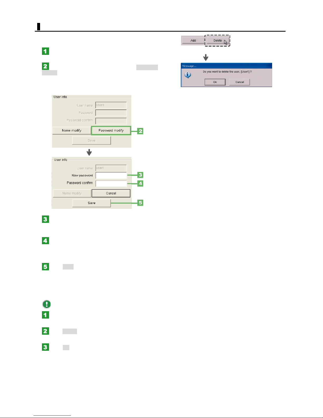
USER/PASSWORD
Changing the password
In the user list (in the [User Setting] section),
select the user whose name you want to change.
In the [User Info] section, Click Password
modify.
The [New password] and [Password confirm] fields are
enabled and the label of the [Password modify] button
changes to [Cancel].
In the [New password] field, type a new
password using the numeric keypad.
Enter a new password with a length of up to 20 characters.
In the [Password confirm] field, type the
password for confirmation using the numeric
keypad.
Re-enter the password you entered in Step 3.
Click Save.
The password has been changed.
Deleting a registered user
You cannot delete "Administrator" and "Guest".
In the user list, click the name of the user you
want to delete.
Click Delete.
The deletion confirmation dialog box opens.
Click OK.
The user has been deleted. The user is no longer listed in
the user list.
47
English
Page 48
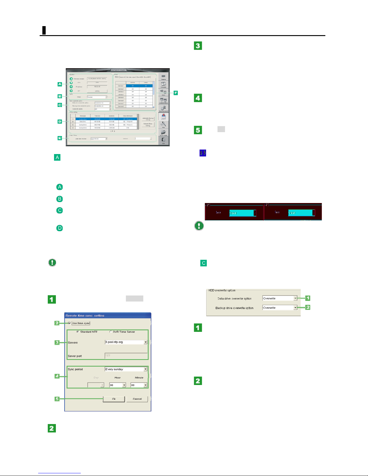
SYSTEM SETTING
Click the [System] setting button to display the System
settings.
Allows you to configure the basic system conditions,
system behaviors when an event occurs, backup
conditions, and other settings.
Using the radio buttons, select the addressing
method and enter address information.
When "Standard NTF" is selected
Type the domain name and port number ("123" by default)
of the server.
When "DVR Time Server" is selected
Type the IP address and port number ("36000" by default)
of the server.
In the [Sync Period] setting, select how often
you want to obtain the time information from the
NTP server and when to synchronize the time
information.
Click OK.
The NTP server has been registered. The dialog box
closes.
Configuring the basic system settings
(System)
These are the basic information on the digital video
recorder.
Version:
Show the S/W version of DVR.
CPU:
Show the CPU usage rate of DVR.
IP address:
The IP address of the digital video recorder you set in the
Communication settings is shown.
NTP:
To automatically adjust the time setting of the digital video
recorder by establishing a connection to an NTP server,
you need to configure the NTP server in the procedure
below.
To use an NTP server, you must have a connection
to the Internet.
Setting an NTP server
In the [NTP] setting, Click Setting.
The [NTP Setting] dialog box opens.
Configuring the UPS
The setting is required if you use an UPS (Uninterruptable
Power Supply).
In the [Model] setting, select "Standard" from the pulldown menu.
Setting Options:
None: UPS not used
Standard: UPS used
You may configure the UPS by clicking the Power
Management (UPS) button in the [System] section of the
[Configuration Setting] dialog box accessible from the
Shell screen.
Configuring the overwrite options (HDD
overwrite option)
You can specify how the digital video recorder behaves if
the hard disk becomes full during recording.
Select the [Use Time Sync] check box.
Now, you can enter information in the dialog box.
Setting the data drive overwrite method (Data
drive)
Setting options:
Overwrite ON:
Continues recording by overwriting data from the oldest
video.
Overwrite OFF:
Stops recording with a message.
Setting the backup drive overwrite method
(Backup drive)
Setting options:
Overwrite ON:
Continues recording by overwriting data from the oldest
video in the drive, if the backup drive becomes full.
Overwrite OFF:
Stops recording with a message, if the backup drive
becomes full.
48
English
Page 49
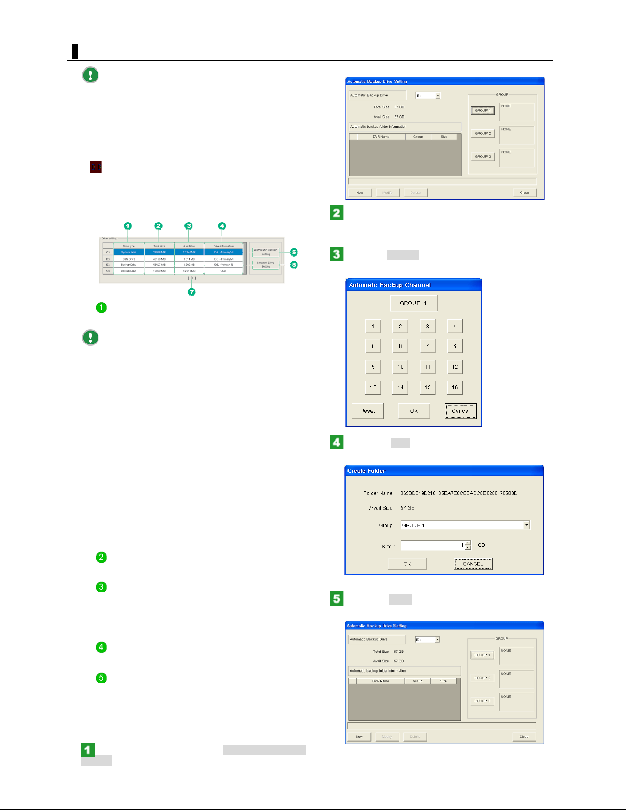
SYSTEM SETTING
The digital video recorder, when stopped in the
"Overwrite OFF" mode, will resume recording if you
change the setting to "Overwrite ON".
However, when recording in the "Overwrite ON"
mode, the digital video recorder will stop recording with a
warning message if you change the setting to "Overwrite
OFF", because the drive capacity is already full.
Confirming the drive settings (Drive setting)
In this section, the drive information recognized by the
operating system is shown.
If you have installed a removable hard disk in the digital
video recorder, configure the drive type and Auto Backup
settings.
The [Automatic Backup Drive Setting] dialog box opens.
Select the [Automatic Backup Drive].
Select the automatic backup drive from the pull-down
menu.
Click the Group1 to set the camera for
autobackup.
Shows the drive type recognized by the system.
Drive type:
By default, the system recognizes any removable
hard disk as "Backup Drive". However, you can change
the drive type to "Data Drive", "Backup Drive", or
"Automatic Backup Drive" from the pull-down menu.
You cannot set the drive type to "Data drive" if the
available disk space on the hard drive is 3 Gbytes or less.
Be sure to power OFF the digital video recorder
before installing or removing a removable hard disk.
If you have changed the drive type to "Automatic
Backup Drive", you need to specify the channel to be
automatically backed up in the [Automatic backup
channel] section.
The recorded data for the specified channel will be
backed up automatically in 64-Mbyte files.
You cannot perform recording and playback if you
set the drive type to other than "Data drive" for all drives.
Even if you have installed an additional hard disk,
you cannot continue recording if an error occurs on that
disk. Be sure to configure the transmission settings on the
[Error HDD] tab so that you can take prompt action in the
event of an error.
Total size:
Shows the total capacity of the drive.
Available:
Shows the available drive space.
This information changes only after you format the hard
disk. It will not be changed even if you change the drive
type.
Click the New to set the autobackup size for
the camera group.
Click the Close to finish the automatic backup
drive setting.
Shows reference information on the drive.
Drive Information:
Automatic backup Setting
If you have an changed the drive type to [Automatic
Backup Drive] in [Drive Type], [Automatic Backup Setup]
is enabled to specify the channel for automatic backup.
<Setting the automatic backup channel>
In the [Drive] setting, Click Automatic Backup
Setting.
49
English
Page 50
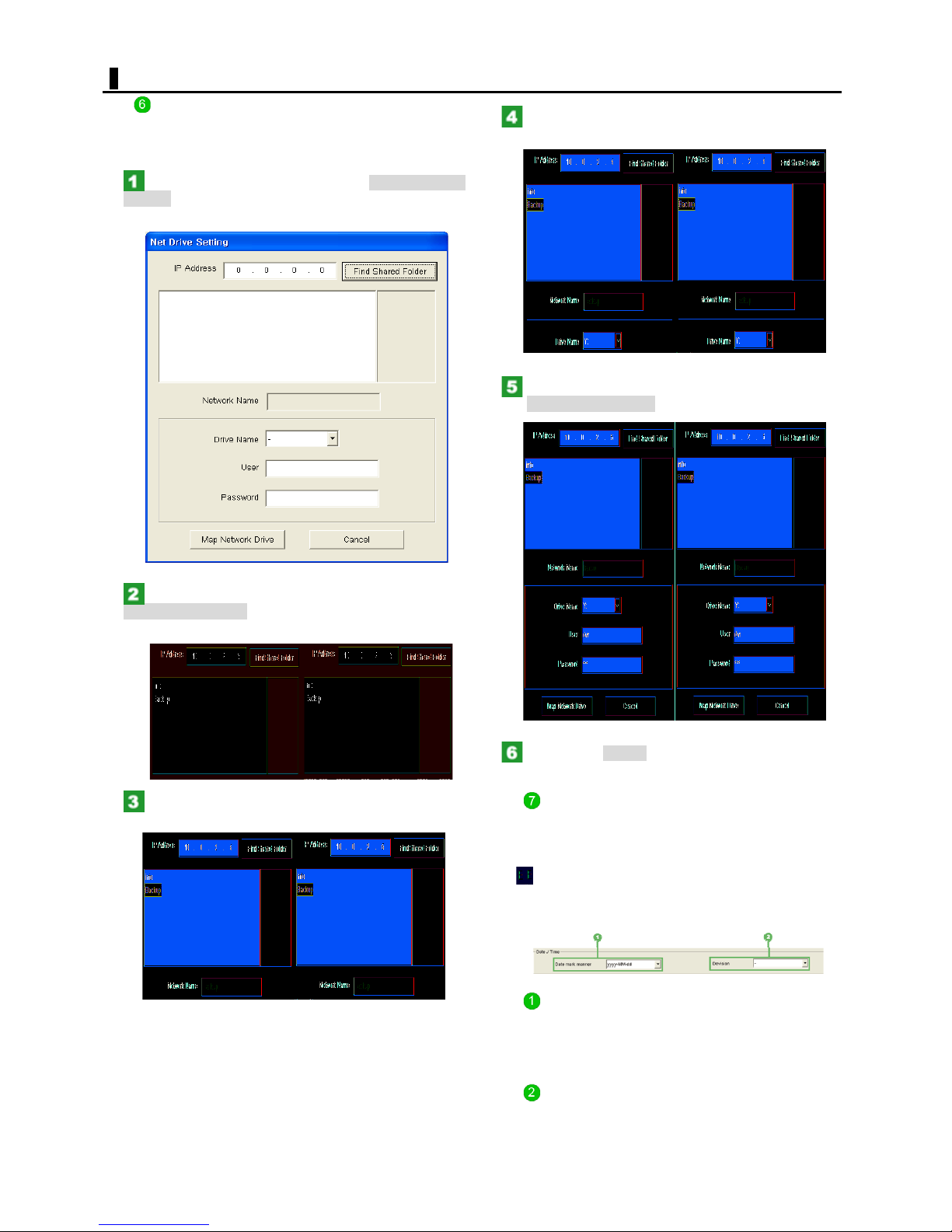
SYSTEM SETTING
Network Drive Setting
Sets the network drive setup for backup or autobackup.
<Setting the network drive>
In the [Drive] setting, Click the Network Drive
Setting.
The [Net Drive Setting] dialog box opens.
Select the network drive name for the
selected folder.
Input the user ID and password and then click
the Map Network Drive.
After inputting the IP address and Click the
Find Shared Folder.
The existing folder on the network drive will be displayed.
Select the folder to use the autobackup or
backup folder.
Click the Cancel to finish the network Drive
Setting.
Blinking drive letter
Shows a blinking letter, which indicates the drive used for
current recording.
Configuring the date display format
(Date/Time)
You can set the date display format and the separator
used for it.
Date mark manner
Select the format of the date shown on the digital video
recorder.
Setting options:
yyyy-MM-dd, MM-dd-yyyy, and dd-MM-yyyy
Select the separator used to separate the year, month,
and day of the date.
Setting options:
Hyphen (-), slash (/), and period (.)
50
Division
English
Page 51
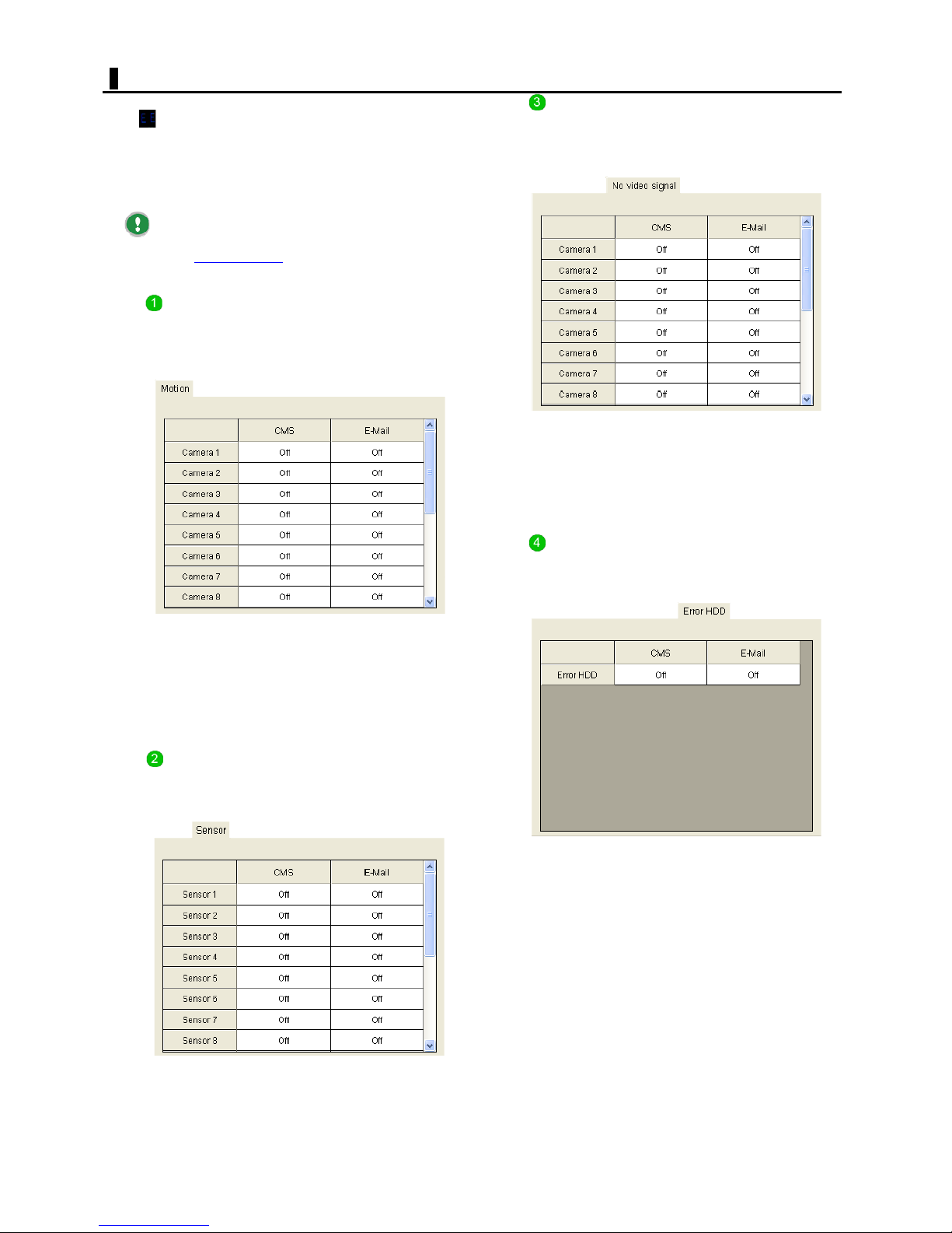
SYSTEM SETTING
Configuring the signal/E-mail transmission
at event occurrence (Event)
You can send a signal or an E-mail to networked
computers if an event occurs.
Click the tab for the desired event and turn On/Off the
signal/E-mail transmission for that event.
This E-mail transmits text information only.
You can specify the destination address of this Email in the [E-Mail address
settings.
Motion
This tab provides the transmission settings for the Motion
event that occurs when any motion is sensed in the target
by the motion sensor.
Turn On/Off the transmission for each camera number.
] field(s) in the Communication
This tab provides the transmission settings for the "No
No video signal
video signal" event that occurs when the video signal is
interrupted.
Turn On/Off the transmission for each camera number.
CMS:
On (Transmits video and text information to networked
computers.)/Off (No transmission)
E-Mail:
On (Transmits an E-mail to the specified E-mail
address.)/Off (No transmission)
CMS:
On (Transmits video and text information to networked
computers.)/Off (No transmission)
E-Mail:
On (Transmits an E-mail to the specified E-mail
address.)/Off (No transmission)
Sensor
This tab provides the transmission settings for the Alarm
IN event that occurs when alarm input is made externally.
Turn On/Off the transmission for each Alarm IN number.
Error HDD
This tab provides the transmission settings for the hard
disk error event that occurs when an error or power
interruption occurs in the hard disk.
CMS:
On (Transmits text information to networked
computers.)/Off (No transmission)
E-Mail:
On (Transmits an E-mail (text) to the specified E-mail
address.)/Off (No transmission)
CMS:
On (Transmits video and text information to networked
computers.)/Off (No transmission)
E-Mail:
On (Transmits an E-mail to the specified E-mail
address.)/Off (No transmission)
51
English
Page 52
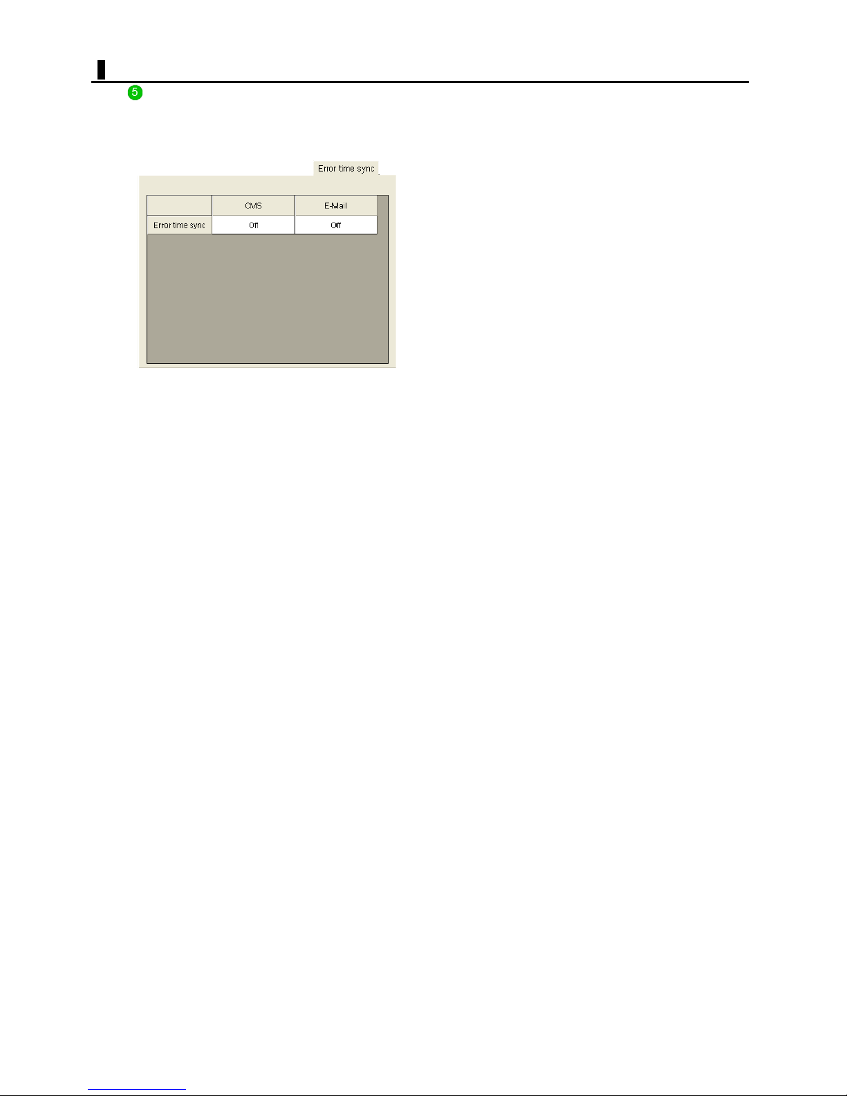
SYSTEM SETTING
Error NTP
This tab provides the transmission settings for the NTP
server error event that occurs when an error occurs in the
NTP server to which the digital video recorder is
connected.
CMS:
On (Transmits text information to networked
computers.)/Off (No transmission)
E-Mail:
On (Transmits an E-mail to the specified E-mail
address.)/Off (No transmission)
52
English
Page 53
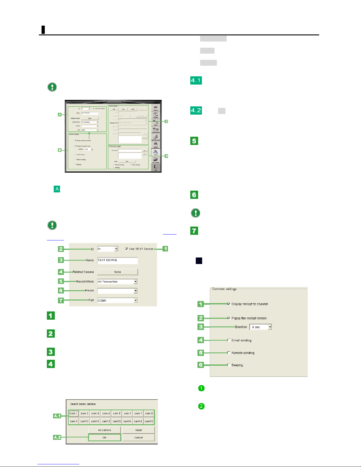
POS SETTING
Click the [Text] setting button to display the Text settings.
On this screen, you can configure settings used, when the
digital video recorder is connected to a text input device
such as a POS or ATM, to record text information from
receipts or payment vouchers together with monitoring
video, so that various alarm features can be used when a
specific keyword(s) is detected in the text.
To connect the digital video recorder to a POS, use
a serial cable via a serial distribution amplifier.
Configuring the basic settings of text input
devices (Device settings)
These are the settings for both the connected text input
device and the camera that works in conjunction with that
text input device.
Before you configure the following settings, you
need to preset the text input device (in the [Preset
settings] section C).
All camera:
Selects all camera numbers.
Reset:
Deselects all camera numbers.
Cancel:
Cancels the settings and closes the dialog box.
Click the camera number you want to link to
the text input device.
This links the camera number to alarm input. You can
select more than one camera number.
Click OK.
The dialog box closes. The button in the [Related Camera]
setting now shows the setting ("None," camera No., or
"All").
In the [Record Mode] setting, select the
recording mode of the digital video recorder.
Setting options:
All Transaction:
Records text information included in all receipts.
Event Trigger Text:
Records text information only if event text is detected in
receipts.
In the [Preset] setting, select the preset name
of the text input device from the pull-down menu.
The pull-down menu shows the preset name of
each text input device you set in [Preset settings].
In the [Port] setting, check the COM port
number.
By default, this is set to "COM1".
Select the [Use TEXT Device] check box.
Now, you can enter device settings.
Assign an ID number (01 to 16) to the text
input device by selecting from the pull-down menu.
Type a name for the text input device.
In the [Related Camera] setting, click the
button (labeled as "None", by default).
The [Select linked camera] setting dialog box appears.
Select the camera that works in conjunction with the text
input device during Text recording.
You can select more than one camera.
Configuring the system behaviors when
issuing a receipt (Common settings)
Specify the system behaviors when a receipt is issued by
selecting or deselecting the check box for each behavior.
Display receipt to channel
Select this check box to enable the on-screen display of
text information included in each receipt.
Popup the receipt screen
Select this check box to enable the on-screen display of
text information included each receipt in a single-screen
layout.
After selecting this check box, specify how long the text
information is displayed in the [Duration] setting.
53
English
Page 54
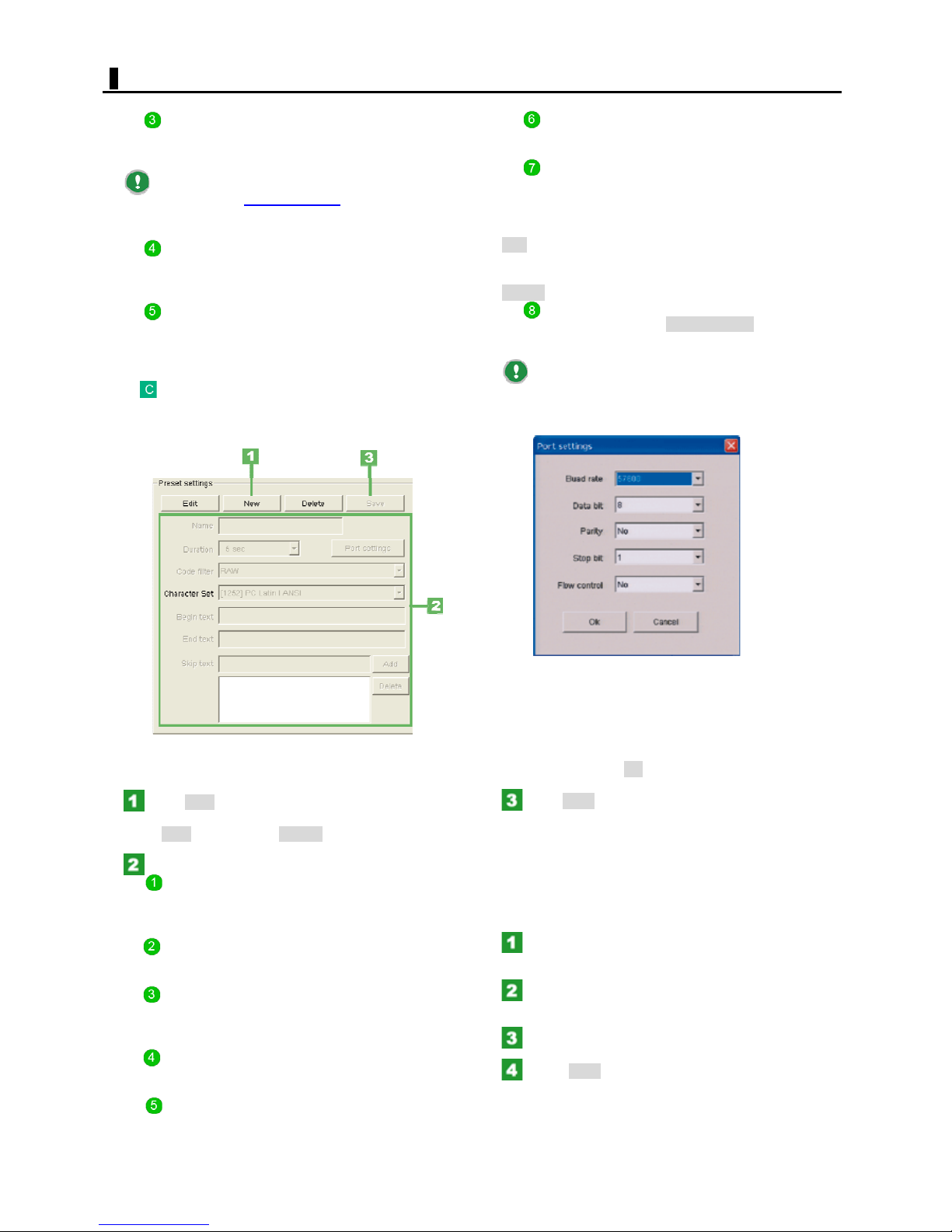
POS SETTING
Email sending
Select this check box to enable the transmission of text
information included in each receipt via E-mail.
You can specify the destination address(es) of this
E-mail in the [E-Mail address
Communication settings.
Remote sending
Select this check box to enable the transmission of text
information included in each receipt to networked personal
computers.
Beeping
Select this check box to enable the beeping of the alarm
buzzer when each receipt is issued.
Presetting a text input device (Preset
settings)
You can preset text input devices you want to connect to
the digital video recorder.
] field(s) in the
End text
The printing of a receipt ends when this text is detected.
You can specify a single text string only.
Skip text
The printing of a receipt is skipped when this text is
detected.
You can specify two or more text strings.
Type the desired text string in the upper box and Click
Add. Then, the text string is listed in order in the lower
box.
To delete a text string, select it in the lower box and Click
Delete.
Port settings
In the Text settings, Click Port settings and configure
the port settings in the following dialog box.
Configure the port to match the text input device's
current communication settings. If the settings are
inconsistent, text information will not be correctly
displayed.
Registering preset positions
Click New.
Now, you can enter device settings. Notice that the label
of the New button is now Cancel.
Configure each of the following settings.
Name
Type a preset name for the text input device.
The set preset name will be listed in the pull-down menu
of the [Preset] setting in Device settings.
Duration
Select the time period (3 to 60 seconds) before each
receipt is printed.
Code filter
Select the communication protocol used for transmission
from the text input device to the digital video recorder.
Character Set
Select the character code transmitted from the text input
device to the digital video recorder.
Begin text
The printing of a receipt begins when this text is detected.
You can specify a single text string only.
Baud rate
Data bit
Parity
Stop bit
Flow control
When finished, Click OK to close the dialog box.
Click Save.
The text input device has been preset. The preset name
will be listed in the pull-down menu of the [Preset] setting
in Device settings.
Modifying a registered preset (Text input
device)
In the Device settings, select the preset name
from the pull-down menu of the [Preset] setting.
Click Edit.
Now, you can enter device settings.
Modify the preset settings.
Click Save.
The preset device settings for the device have been
modified.
54
English
Page 55
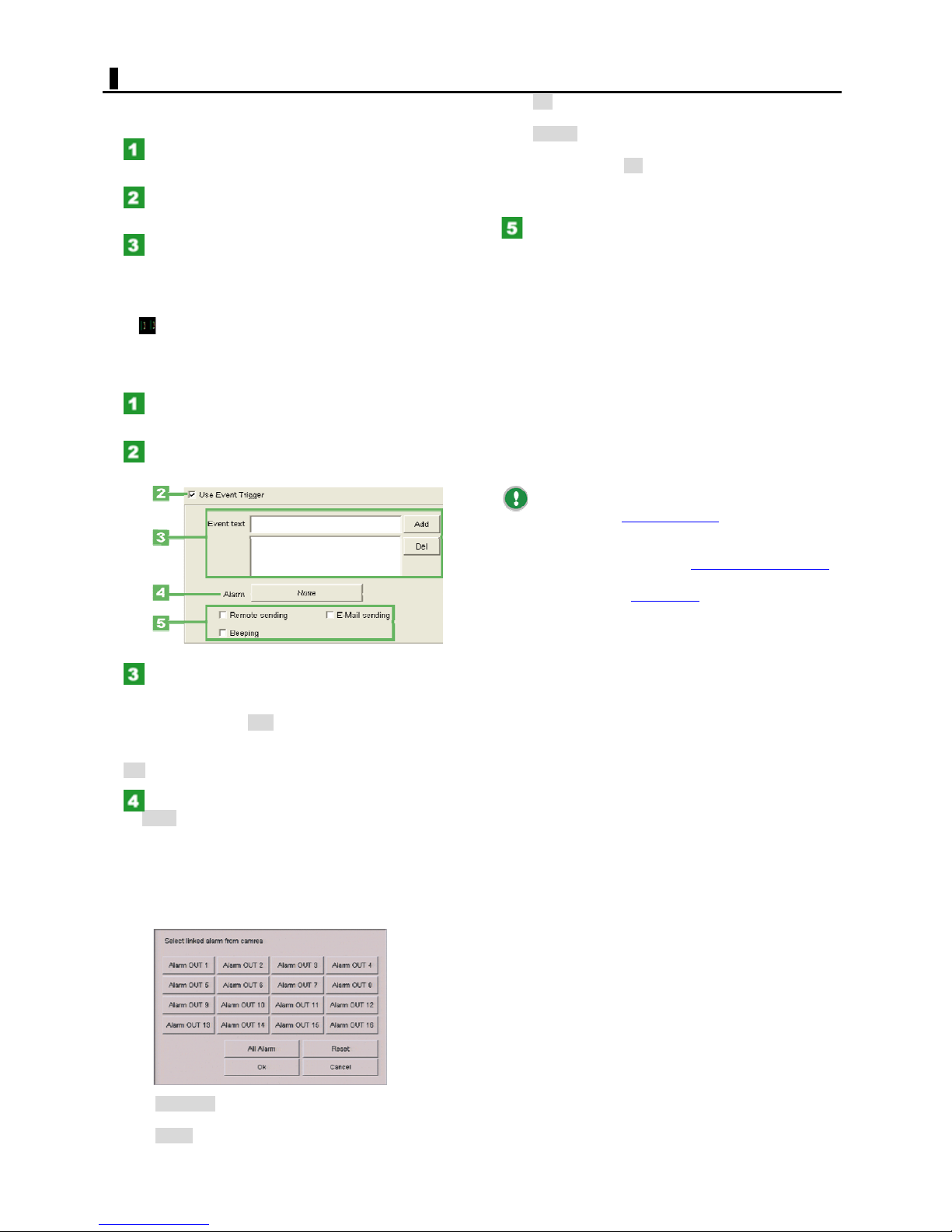
POS SETTING
Deleting a registered preset (Text input device)
In the Device settings, select the preset name
in the [Preset] setting.
Click Delete.
The deletion confirmation dialog box opens.
Click OK.
The preset name disappears from the pull-down menu of
the [Preset] setting in Device settings.
Configuring the event trigger text (Use Event
Trigger)
You can configure the alarm trigger so that an alarm event
is raised when a specific keyword(s) is detected in the text.
Select the [Use TEXT Device] check box.
The [Use Event Trigger] check box is now selectable.
Select the [Use Event Trigger] check box.
Now, you can enter device settings.
OK:
Saves the settings and closes the dialog box.
Cancel:
Cancels the settings and closes the dialog box.
When finished, Click OK.
The dialog box closes. The button in the [Alarm] setting
now shows the setting ("None," alarm OUT No., or "All").
Configure other linked operation
Configure other actions you want to trigger if event trigger
text is detected.
Select the check box for each action you want to trigger.
You can select more than one action.
Remote sending:
Select this check box to enable the transmission of text
information included in each receipt on which event text is
detected to networked personal computers.
Email sending:
Select this check box to enable the transmission of text
information included in each receipt on which event text is
detected via E-mail.
Beeping:
Select this check box to enable the beeping of the alarm
buzzer when event text is detected.
You can specify the destination address(es) of this
E-mail in the [E-Mail address
Communication settings.
To record monitoring video using event text as the
alarm trigger, you need to set a Text recording schedule
Schedule settings.
Performing a Tex t se arch
allows you to search for specific video and text by using
keywords from among the data recorded in Text recording.
] field(s) in the
in
on the SEARCH screen
In the [Event text] setting, type an event
trigger keyword in the upper box.
You can specify two or more keywords.
When finished, Click Add. Then, the text is listed in order
in the lower box.
To delete a keyword, select it in the lower box and Click
Del.
In the [Alarm] section, click the button (labeled
as None by default).
The [Select linked alarm from camera] setting dialog box
appears.
In this dialog box, select the alarm OUT number of the
terminal, from which you want to output an alarm signal
when the event trigger keyword(s) is detected.
You can select more than one alarm out.
All Alarm:
Selects all alarm OUT numbers.
Reset:
Deselects all alarm OUT numbers.
55
English
Page 56
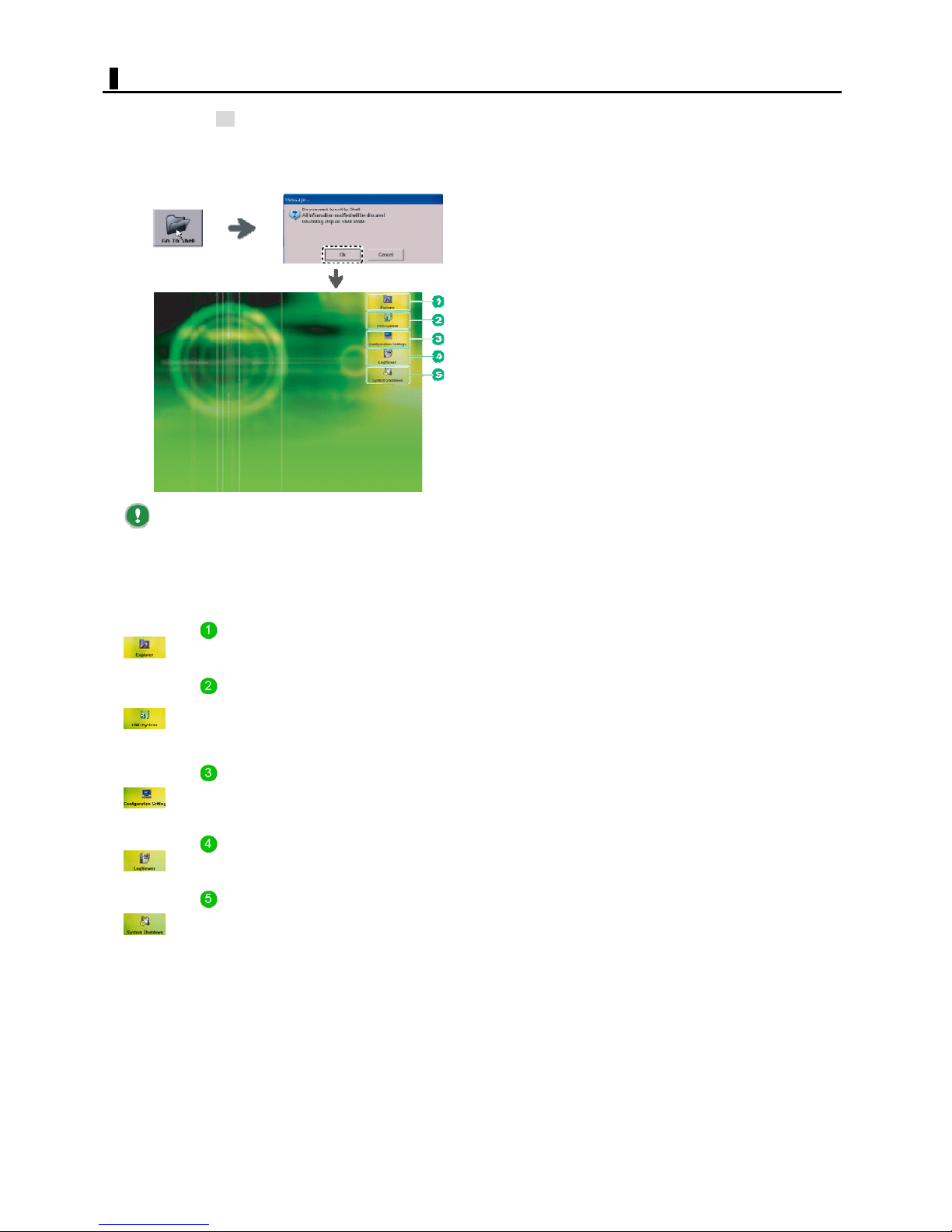
GO TO SHELL
Click the [Go To Shell] button on the SETTINGS screen
and then Click OK in the confirmation dialog box. Then,
the system's operation window closes and the Shell screen
(desktop) appears.
On the Shell screen, you select operations from five menu
icons.
Switching to the Shell screen discards all the
settings you configured on the SETTINGS screen.
Before clicking the [Go To Shell] button, once click
[Exit] to save the changes.
While the Shell screen is displayed, the digital video
recorder stops all recording behaviors.
Explorer
Allows you to perform standard Windows
operations.
DVR System
Starts the system in the operation mode and
displays the [Login] screen. Once you have
logged into the system, the LIVE screen
appears.
Configuration Setting
Displays the [Configuration Setting] screen,
where you can configure the system
environment.
LOG Viewer
Displays the [LOG Viewer] screen, where you
can check the log history of DVR system.
System Shutdown
Shuts down the system. Clicking this button
causes the Shell screen to close the digital
video recorder to power OFF automatically.
56
English
Page 57
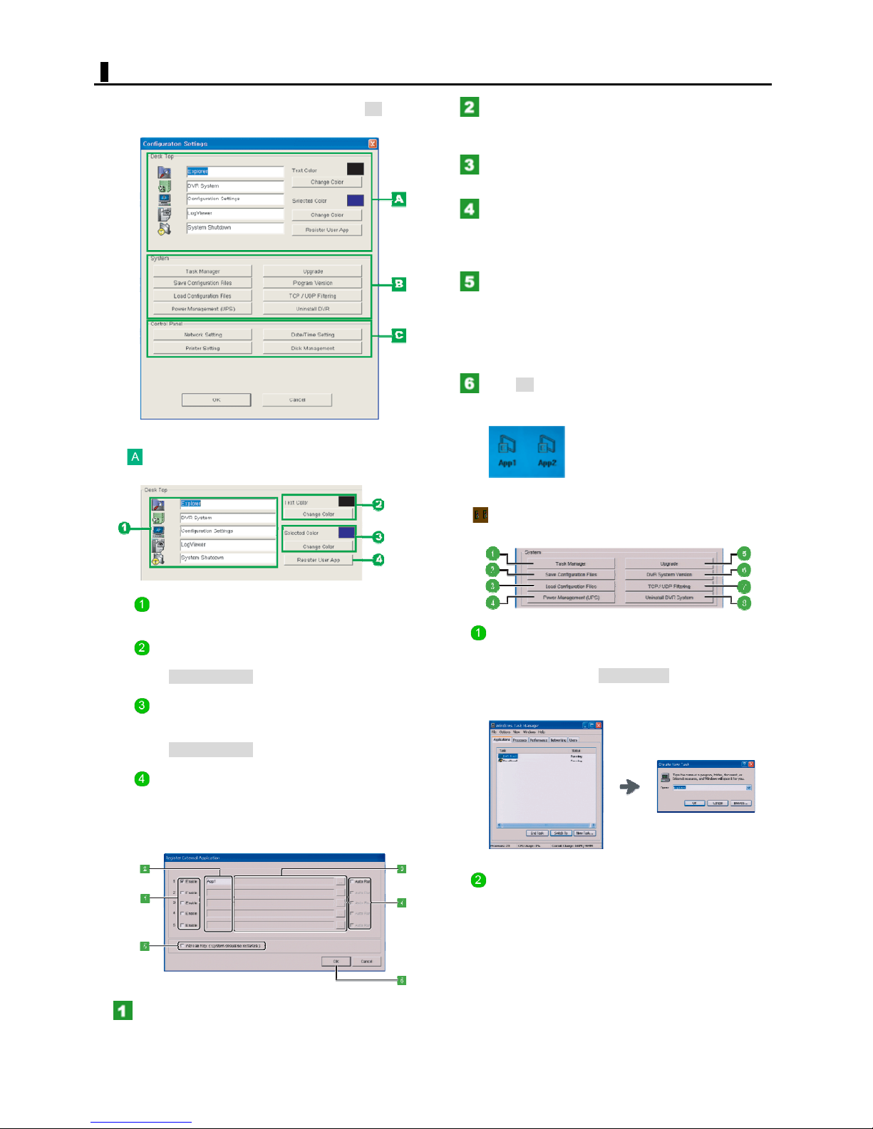
SHELL SETTING
In this dialog box, configure the system environment of
the digital video recorder. When finished, Click OK to close
the dialog box.
Configuring the desktop appearance (Desk
Top)
Type the name of the application you want to
register.
Default setting: App1 to App5
Click the button and select the storage location
of the application files.
Select the [Auto Run] check box to enable the optional
Auto Run feature.
Selecting the check box causes the application to start
automatically when the system starts up.
Select the [Alt+Tab key] check box to enable
"Alt+Tab" key combination.
Selecting the check box enables the "Alt+Tab" key
combination, which allows you to switch to the desired
application that is running from the system's operation
screen.
Click OK.
The icon for each application you registered appears at
the bottom of the screen.
Icon labels
To change the default label of each icon, type a new label
in the text box.
Text Color
The currently set text color of the icons is shown.
Click the Change Color. Then, the [Color] dialog box
opens, allowing you to change the text color.
Selected Color
The currently set text color of the icons when selected is
shown.
Click the Change Color. Then, the [Color] dialog box
opens, allowing you to change the text color.
Register User App
You can register up to five user applications you want to
use with this digital video recorder.
Click the button and register the desired applications in
the [Register External Application] window.
Configuring the basic system settings
(System)
Button to create new tasks (Task Manager)
Clicking this button displays the [Windows Task Manager]
window.
To start a new task, Click New Task... and, in the [Create
New Task] dialog box, type the name of the task you want
to create.
Button to save the system configuration
(Save Configuration Files)
Click the button and, in the [Save Configuration] dialog
box, select the folder into which you want to save the
system configuration.
The settings you configured in this dialog box are stored
as configuration files.
Select the [Enable] check box.
This enables the registration of a user application.
57
English
Page 58
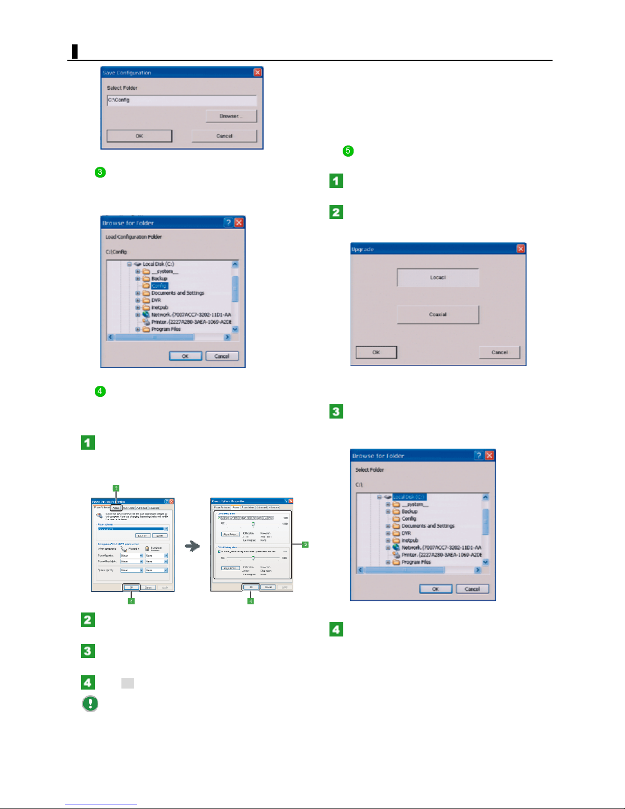
SHELL SETTING
Button to load the stored configuration files
(Load Configuration Files)
Click the button and, in the [Browse for Folder] dialog box,
select the configuration file you want to load.
2) Saves the data currently in memory to the hard
disk.
3) Shuts down the digital video recorder if the
battery runs out.
The history of these operations is saved as
operation logs.
Button to update the system program
(Upgrade)
Click Upgrade.
The [Upgrade] dialog box opens.
Select the button for the type of program you
want to update and Click OK.
The [Browse for Folder] dialog box opens.
Button to configure the UPS (Power
Management (UPS))
You can configure the UPS in the [Power Options
Properties] dialog box.
Click Power Management (UPS).
The [Power Options Properties] dialog box opens.
When the digital video recorder is connected to a UPS, the
dialog box shows the [Alarm] tab.
Click the [Alarm] tab.
The settings on the [Alarm] tab appear.
Configure the [Low battery alarm] and [Critical
battery alarm] settings.
Setting options:
Local:
Select the folder where the program files you
want to update are stored and Click OK.
The files to be updated appear in the [Upgrade] dialog
box.
Select the check box for each file you want to
update in the file list and Click OK.
The selected files are updated.
Click OK to save the settings.
Connecting an UPS to the digital video recorder
causes the system to perform the operations in the event
of a power failure.
1) Switches the power supply to the connected
UPS and beeps if the [Low battery alarm] or
[Critical battery alarm] value is reached.
58
English
Page 59
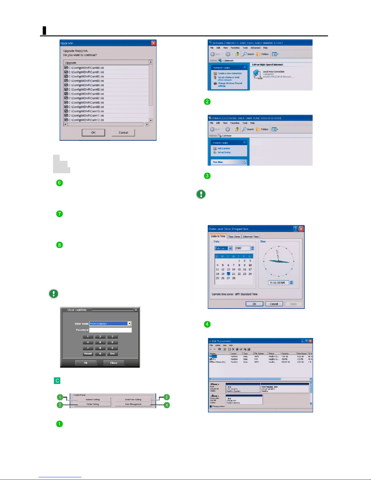
SHELL SETTING
<Other buttons>
All: Selects all check boxes.
Reset: Deselect all check boxes.
Cancel: Cancels the settings and closes the dialog box.
Button to show the system version (DVR
System Version)
Click this button to view the program version and the
model name of the digital video recorder.
Button to configure the filters (TCP/UDP
Filtering)
Click this button to configure the network connection
filters.
Button to configure the printer tasks
(Printer Setting)
Button to configure the date and time
settings (Date/Time Setting)
If this is the first time you powered ON the digital
video recorder, you need to switch to the Shell screen
from the SETTINGS screen and click this button to
configure the date and time settings.
Button to uninstall the system programs
(Uninstall DVR System)
Click this button to uninstall the system programs installed
in the digital video recorder.
To uninstall the system programs, you need to enter a
valid "Administrator" password in the [User Confirm]
window.
Only "Administrator" users can uninstall the system
programs.
Displaying the standard Windows control
panel (Control Panel)
Button to manage the disks (Disk
Management)
Button to configure the network tasks
(Network Setting)
59
English
Page 60
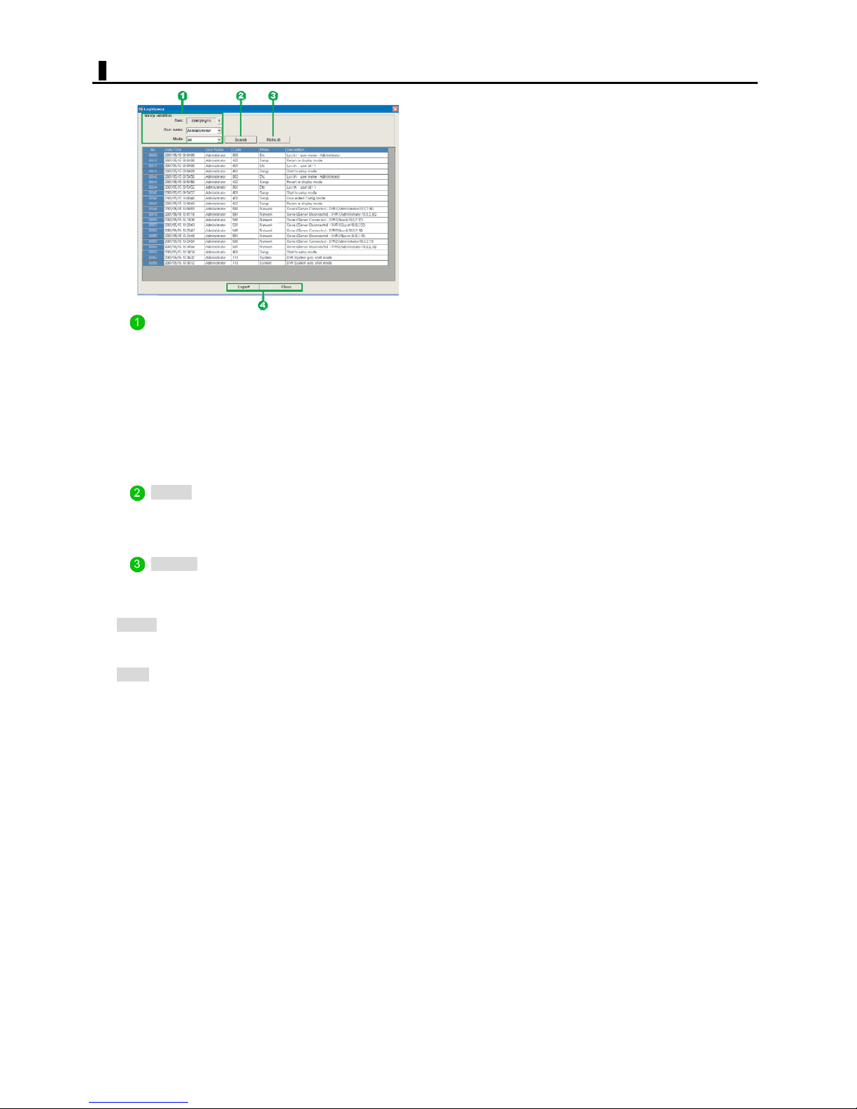
LOG VIEWER
Query condition
Allows you to set the query conditions to search for the
logs.
Date: Click the Calendar button and specify the year,
month, and day of the operations you want to
query for.
User ID: Select the user name in the pull-down menu.
Mode: Select the operation mode in the pull-down
menu.
Search
Starts a query search. The searched logs will be listed in
chronological order, from older to newer operations.
Refresh
Refreshes the screen information.
< Other buttons>
Export: Saves the logs displayed on the screen.
Click the button and, in the [Save As] dialog
box, set the saving conditions.
Close: Closes the [Log Viewer] screen.
60
English
Page 61
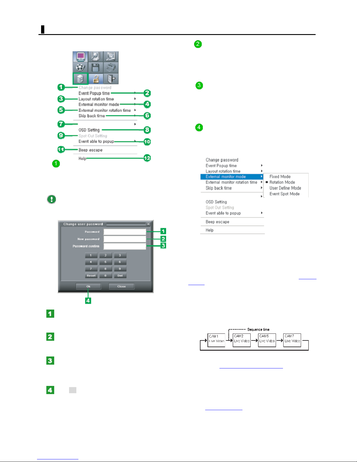
ETC
Clicking the [ETC] mode button causes the following pulldown menu to appear, presenting various options.
Event popup time
Provides options related to the Event Popup feature.
Set the time during which alarm video is displayed if an
alarm event occurs.
Options: 1 to 10, 12, 14, 16, 18, 20, 25, and 30 sec
Layout sequence time
Provides options related to the automatic screen switching
feature.
Set the interval at which the displayed video is switched.
Options: 1 to 10, 12, 14, 16, 18, 20, 25, and 30 sec
Server to Server
Change password
Allows the current login user to change his/her password.
Selecting this menu command displays the [Change user
password] screen, where you can change your password
in the following procedure.
If you are using the default user names, "Guest" or
"Administrator", you cannot use this menu command to
change your password.
External Monitor mode
Sets the display mode of the spot monitor connected to
the digital video recorder.
Configure the related settings depending on the display
mode.
Server to Server
Fixed Mode:
Fixes the channel from which you can monitor video to a
single channel.
<Related setting>
In the Camera Information panel, right-click one of
the channels and, in the context menu, select [External
Monitor] to turn On (a checkmark appears) the output to
the spot monitor.
By default, video from Camera 1 is displayed.
In the [Password] field, type your current
password.
To do so, use the numeric keypad.
In the [New password] field, type a new
password.
Enter a new password with a length of up to 20 characters.
In the [Password confirm] field, type the new
password again.
For confirmation, re-enter the new password you entered
in Step 2.
Click OK.
Your password has been changed and the [Change user
password] screen closes.
Rotation Mode:
Displays video from all channels (CH1 to CH16) in the
order of channel numbers by automatically switching the
screens.
<Related setting>
Select [External monitor rotation tim
menu to set the time until the displayed video is switched.
User Define Mode:
Allows you to configure automatic switching patterns by
setting the channel from which you monitor video, video
display sequence, video switching time, etc.
Select [Spot Out Setting
conditions.
61
] in this menu to set the display
e] 5 in the ETC
English
Page 62
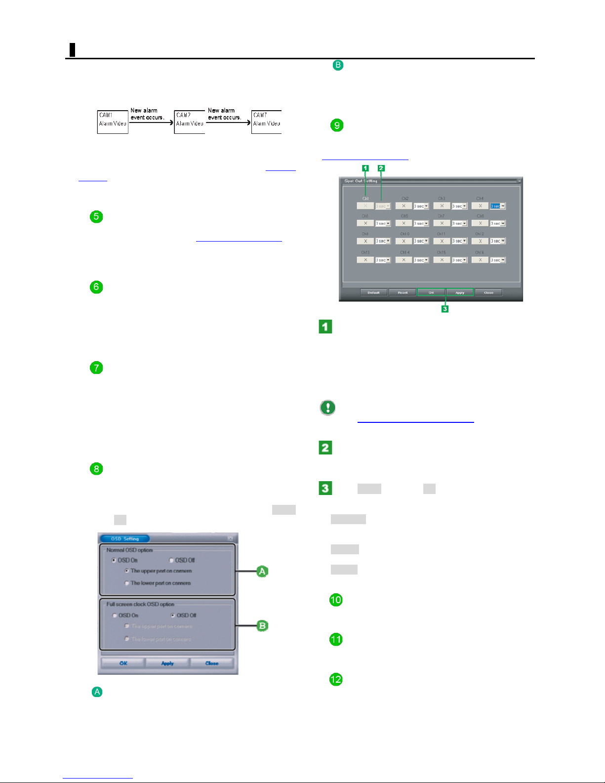
ETC
Event Spot Mode:
Displays alarm video if an alarm event occurs.
The alarm video will be retained until the next alarm event
occurs.
<Related setting>
In the Camera Information panel, right-click one of
the channels and, in the context menu, select [External
monitor] to turn On (a checkmark appears) the output to
the spot monitor. You can select more than one channel.
External monitor rotation time
Allows you to set the time until the displayed video is
switched, if you have set the [External Monitor mode
"Sequence Mode".
Options: 1 to 10, 12, 14, 16, 18, 20, 25, and 30 sec
Skip back time
In One Channel Search, the digital video recorder starts
playing back the video after skipping back for the set time
from the last recorded point.
Using this menu command, you can set the skip back time.
Options: 30/45 sec, 1 to 5 min, and 10 min
Server to Server
Register a remote DVR:
Allows you to register the DVR servers you want to
emulate from the digital video recorder.
Arrange all Server to Server window:
Allows you to switch the appearance of the cascading
screen display when the digital video recorder is
connected to more than one DVR server.
OSD Setting:
Displays the [OSD Setting] screen, where you can turn
On/Off the on-screen video information display as well as
the display position.
When finished configuring the OSD settings, click Apply
and then OK.
] to
Full screen clock OSD option
To display the clock information in the full-screen mode,
turn On the "OSD On" radio button and then select the
desired display position (upper/lower part).
Spot Out Setting
Displays the [Spot Out Setting] screen, where you can
configure automatic switching patterns if you have set the
[ External Monitor mode
Click the Channel (Ch) button.
This toggles the output mode of the selected channel to
the spot monitor between "Show" (the display sequence
number appears) and "Hide" ("X" appears).
Switching the Spot Out mode from "Show" to "Hide"
automatically adjusts the display sequence numbers for
other channels.
You cannot set the Spot out mode for channels for
which the [Camera] (camera type) setting
screen is configured to "None" or "LAN".
Using the pull-down menu next to the Ch
setting, set for each channel how long the video
output is made to the spot monitor.
Click Apply and then OK.
<Other buttons>
Default: Automatically sets the display sequence
numbers for all channels in an ascending order and the
output time to the spot monitor uniformly to "3 sec".
Reset: Sets the Spot Out mode to "Hide" for all
channels.
Close: Cancels the Spot Out setting and closes the
screen.
] to "User Define Mode".
on the SETTING
Normal OSD option
To display the video information in the normal display
mode, turn On the "OSD On" radio button and then select
the desired display position (upper/lower part).
Event able t
Popup the camera image when motion or sensor is trigger
ed..
Beep escape
Mutes the alarm beep that will be output if an event
occurs.
Help
Click this icon to display the online manual for the digital
video recorder.
62
o popup
English
Page 63
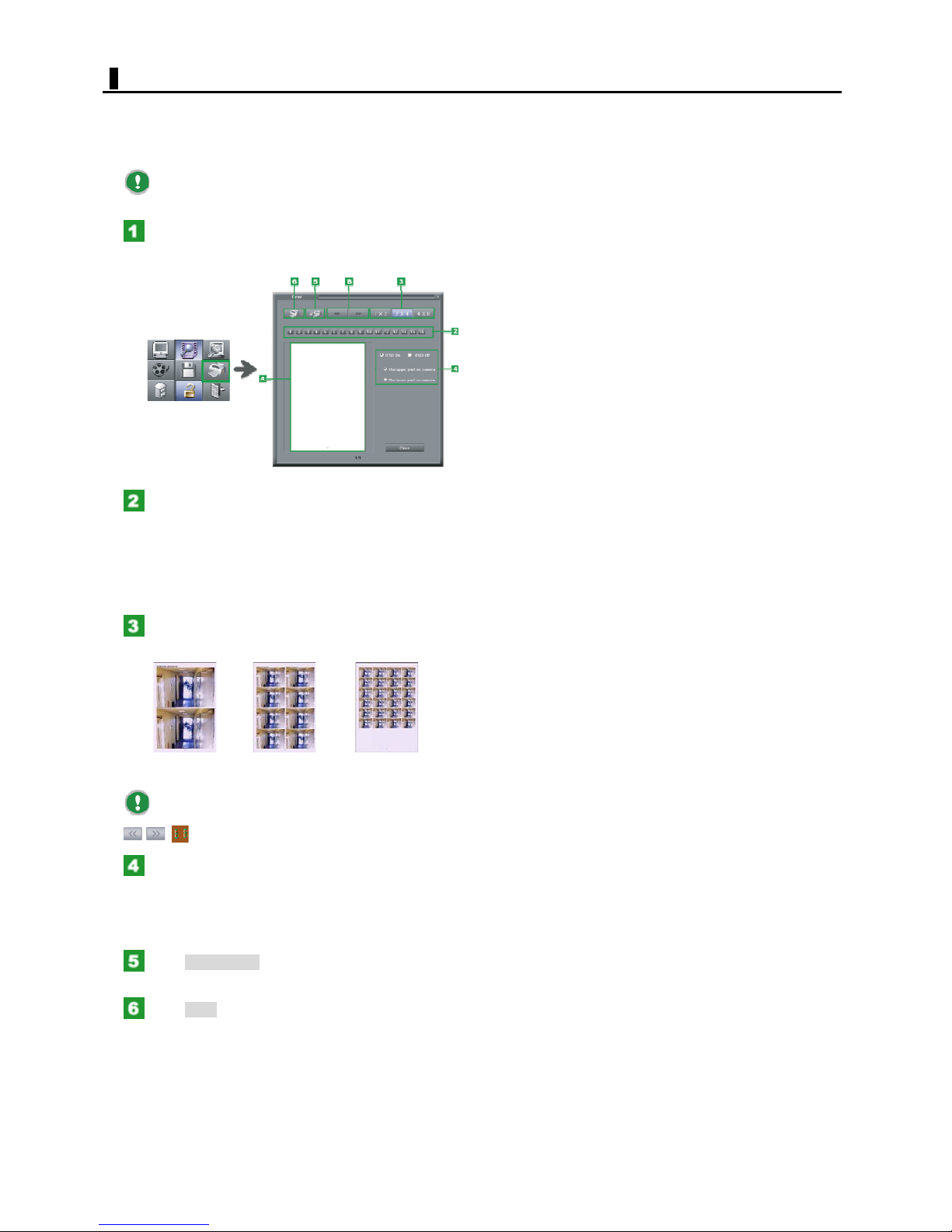
PRINTING
The SEARCH screen allows you to print and copy the video
images being played back.
You can print still images of the video you searched for
playback.
Before starting printing, you must install a printer
driver in the digital video recorder.
Click the [PRINT] mode button while the
searched video is being played back or suspended.
The [Print] screen appears.
Click the channel number for the video you
want to print.
You may select more than one channel. The video images
for the selected channel appear in order in the Preview
area A.
To clear the images in the Preview area, click the channel
number button again.
Click the Print Layout button corresponding to
the desired printing layout (horizontal x vertical).
1x2 2x4 4x8
If there are two or move preview pages, you can
switch to the previous or next page by clicking
.
Select the OSD On/OSD Off radio button to
show/hide the video information on each image.
If you select "OSD On", select the radio button
corresponding to the display position (upper/lower part) of
the video information.
Click Print Setup and perform print setup in the
[Print] dialog box.
Click Print.
The video images from the channel you specified are
printed using the specified layout.
63
English
Page 64
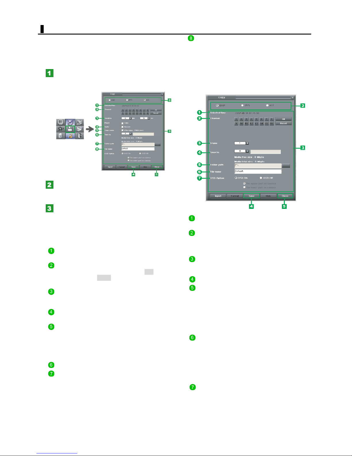
COPYING
You can copy the video being played back to a CD/DVD,
USB memory, removable hard disk, or other recording
media.
Select the copy-destination drive and then perform the
following operation.
Click the [COPY] mode button while the
searched video is being played back or suspended.
The [Copy] screen appears.
Select the radio button corresponding to the
format in which you want to save the video images.
Available formats: BMP, JPG and AVI
File Name: Type a file name if you want to name it by
yourself.
By default, the system sets the following
file name:
<CH number>_<recording date (8 digits)
and recording time (6 digits)>_<Serial
number (3 digits)>.<File extension>
When you selected "BMP" or "JPG"
Set the copying conditions.
The copying condition settings differ depending on the
saving format you selected.
When you selected "AVI" (for moving images)
Selected
Time:
Channel: Select the copy-source channel number.
Duration: In the [Duration] section, specify how
Audio: Select this check box to copy also the
Copy
Codec:
Save to: Select the copy-destination drive.
Folder
path:
Shows the recording date and time of
the video from which the copying starts.
To select all channels, click ALL.
Click Reset to deselect all of the selected
channels.
long you want to copy the video in
minutes and seconds.
audio signals.
To play back AVI files using a personal
computer, you need to install the
MPEG4.Codec (PMK4.exe).
Selecting this check box allows the system
to automatically copy the MPEG4.Codec
together with video data.
Click the button next to the [Folder path]
field and, in the [Select the folder] dialog
box, select the desired copy-destination
folder.
The selected folder path appears, together
with the available space and the total
capacity of the copy-destination drive.
Selected
Time:
Channel: Select the copy-source channel number.
Frame: In the [Duration] section, specify how
Save to: Select the copy-destination drive.
Folder
path:
File
Name:
OSD
Option:
Shows the recording date and time of
the video from which the copying starts.
To select all channels, click ALL.
Click Reset to deselect all of the selected
channels.
long you want to copy the video in the
number of frames (1 to 10).
Click the button next to the [Folder path]
field and, in the [Select the folder] dialog
box, select the desired copy-destination
folder.
The selected folder path appears,
together with the available space and the
total capacity of the copy-destination
drive.
Type a file name if you want to name it
by yourself.
By default, the system sets the following
file name:
<CH number>_<recording date (8
digits) and recording time (6
digits)>_<Serial number (3
digits)>.<File extension>
To copy also video information displayed
with each image, turn On the "OSD On"
radio button and then select the desired
display position (upper/lower part) of the
video information.
64
English
Page 65

COPYING
Click Save.
The system starts copying the specified portion of the
video.
Until the copying is finished, you cannot perform
any operation on the SEARCH and SETTINGS screens.
If the copy-destination medium becomes full during
coping, the system will cancel the copying process and
present a message dialog box.
The portion until the copying is cancelled is
effective.
Click Close.
The [Copy] screen closes.
Other buttons
Eject/Inject: Opens and closes the tray if the copy
destination is the E drive (CD-RW/DVD).
Format: Initializes the inserted recording medium if
the copy destination is the E drive (CD-RW
or DVD).
Clicking this button opens the [Format
Disk] dialog box. Confirm the initialization
settings and click Start.
Hide: Minimizes the [Copy] screen into an icon in
the status bar, while continuing the copying
process.
65
English
Page 66
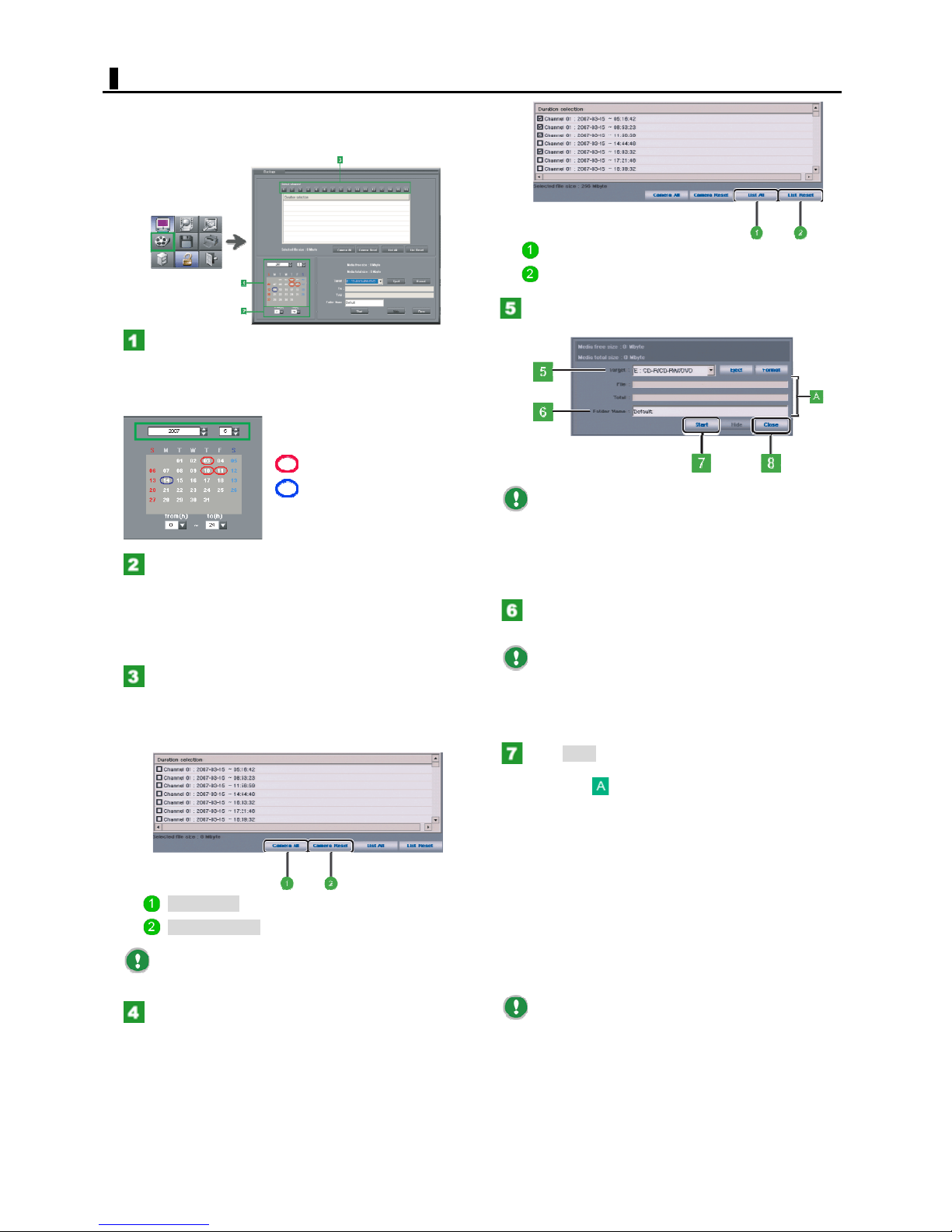
DATA BACKUP
You can back up the data recorded from the specified
channel in 64-Mbyte files.
On the LIVE screen, click the [DATA BACKUP] mode
button. The [DATA Backup] screen appears.
In the calendar, specify the day on which the
data you want to back up was recorded by clicking
a red circle.
Specifying the year and month changes the calendar
content accordingly.
: Day with recorded data
: Day currently selected.
In the [from (h)] and [to (h)] settings, specify
the duration of the recorded data you want to
backup.
Note that you can specify only the hour portion of the
recording time.
By default, this is set to "00" to "24" o'clock (all day).
Click the channel number for the data you want
to backup.
In the [Duration selection] list, the recording date and
time information on each channel appears for the selected
date.
List All: Selects all recorded data listed.
List Reset: Deselect all recorded data listed.
In the [Target] setting, select the backupdestina
the available space and the total capacity of the backup
medium are shown.
Confirm the total size of the files you selected does
not exceed the size of the available space in the backup
medium.
In the [Folder Name] field, type the desired file
name if you want to name it by yourself.
name:
<DVRBackup>_<Year-month-date of recording (8
digits)>_<Recording time (6 digits)>
Click Start.
The system starts a backup, showing its progress as a
progress gauge .
When the backup process is finished, a dialog box opens,
showing the backup has been finished.
tion drive.
In the [Media free size/ Media total size] section,
By default, the system sets the following folder
Camera All: Selects all channel numbers.
Camera Reset: Deselects all channel numbers.
Each recorded data listed represents a 64-Mbyte
file.
Select the check box for each recorded data
you want to back up.
The total file size of the recorded data (calculated by
multiplying 64 Mbytes by the number of the selected files)
is shown as [Selected file size] at the lower part of the
[Duration selection] screen.
When the backup destination is a CD/DVD
File: Indicates the writing status from the buffer to the
backup medium.
Total: Indicates the writing status to the buffer.
When the backup destination is a removable
disk
File: Indicates the progress of writing each file.
Total: Indicates the progress of writing all files, if there
are more than one file.
If the backup medium runs out of space, the
system will present a message dialog box.
During an auto backup, you cannot perform manual
backup from this screen until the backup of each file is
finished.
Until the backup is finished, you cannot perform
any operation on the SEARCH and SETTINGS screens.
66
English
Page 67
DATA BACKUP
Click Close.
The [Backup] screen closes.
Other buttons
Eject/Inject: Opens and closes the tray if the backup
destination is the E drive (CD-R/CDRW/DVD).
Format: Formats the backup medium if the backup
destination is the E drive (CD-R/CDRW/DVD).
Clicking this button opens the [Format
Disk] dialog box. Confirm the initialization
settings and click Start.
[Backup] icon turns to yellow in the status bar, while
continuing the backup process.
to
67
English
Page 68
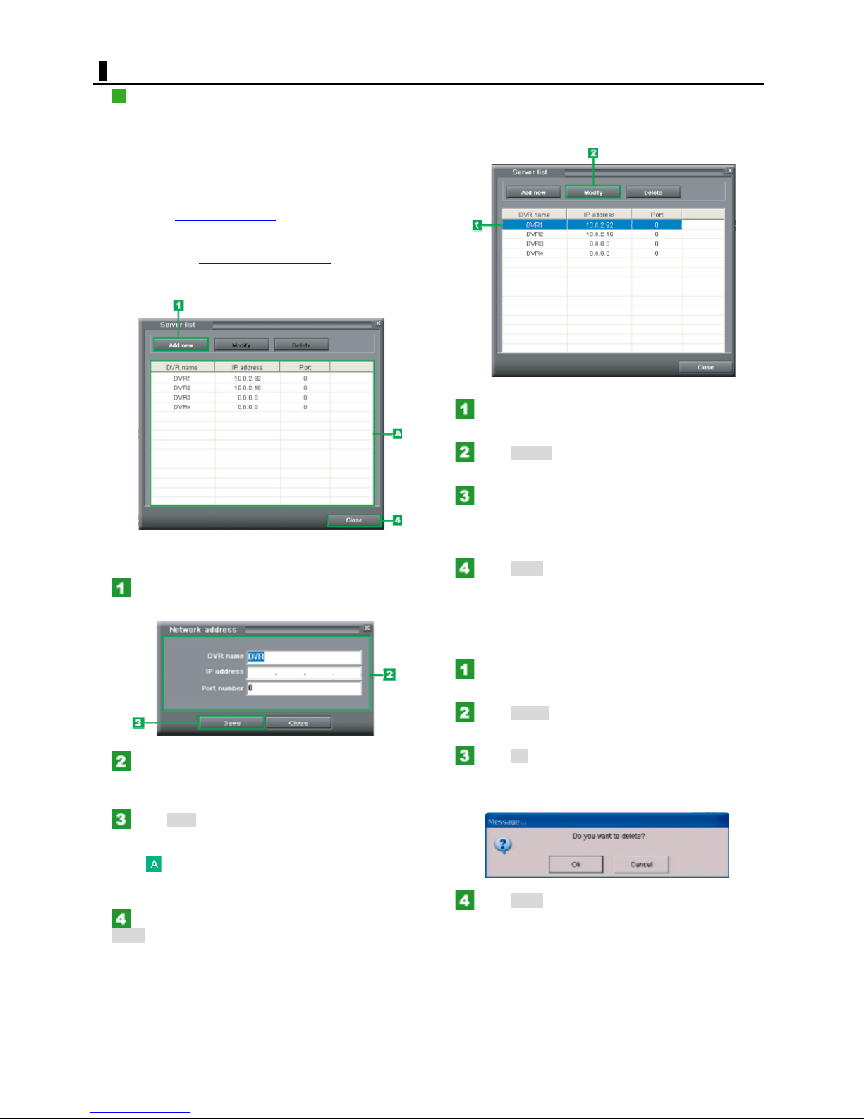
SERVER TO SERVER
REGISTERING A DVR SERVER
This digital video recorder offers the "Server to Server"
feature, allowing you to emulate up to four networked
DVR servers.
You can register DVR servers on the [Server List] screen.
The [Server List] screen can be displayed using either of
the following methods.
Modifying a registered DVR server setting
Click [Server to Server
select [Register a remote DVR].
In the context menu that appears by rightclicking the [Server to Server]
Camera Information panel, select [Register a
remote DVR].
The above shows an example screen after registering DVR
servers.
Click Add new.
The [Network address] dialog box opens.
] in the ETC menu, and
folder on the
In the server list, select the desired DVR server.
The selected line is now highlighted.
Click Modify.
The [Network address] dialog box opens.
Modify the desired registered setting and click
Save.
The [Network address] dialog box closes. The content of
the server list has been updated.
Click Close.
The [Server List] screen closes.
Enter network information (DVR name/IP
address/Port number) on the DVR server you want
to register.
Click Save.
The [Network address] dialog box closes and the
information on the registered DVR server appears in the
server .
To register the next and later DVR servers, repeat the
same steps (Steps 1 to 3).
When finished registering all DVR servers, click
Close.
The [Server List] screen closes and, on the Camera
Information panel, the names of the registered DVR
servers are listed in the tree list.
Deleting a registered DVR server
In the server list, select the desired DVR server.
The selected line is now highlighted.
Click Delete.
The deletion confirmation dialog box opens.
Click OK in the dialog box.
The selected DVR server disappears from the server list.
The name of the deleted DVR server disappears from the
tree list in the Camera Information panel.
Click Close.
The [Server List] screen closes.
68
English
Page 69
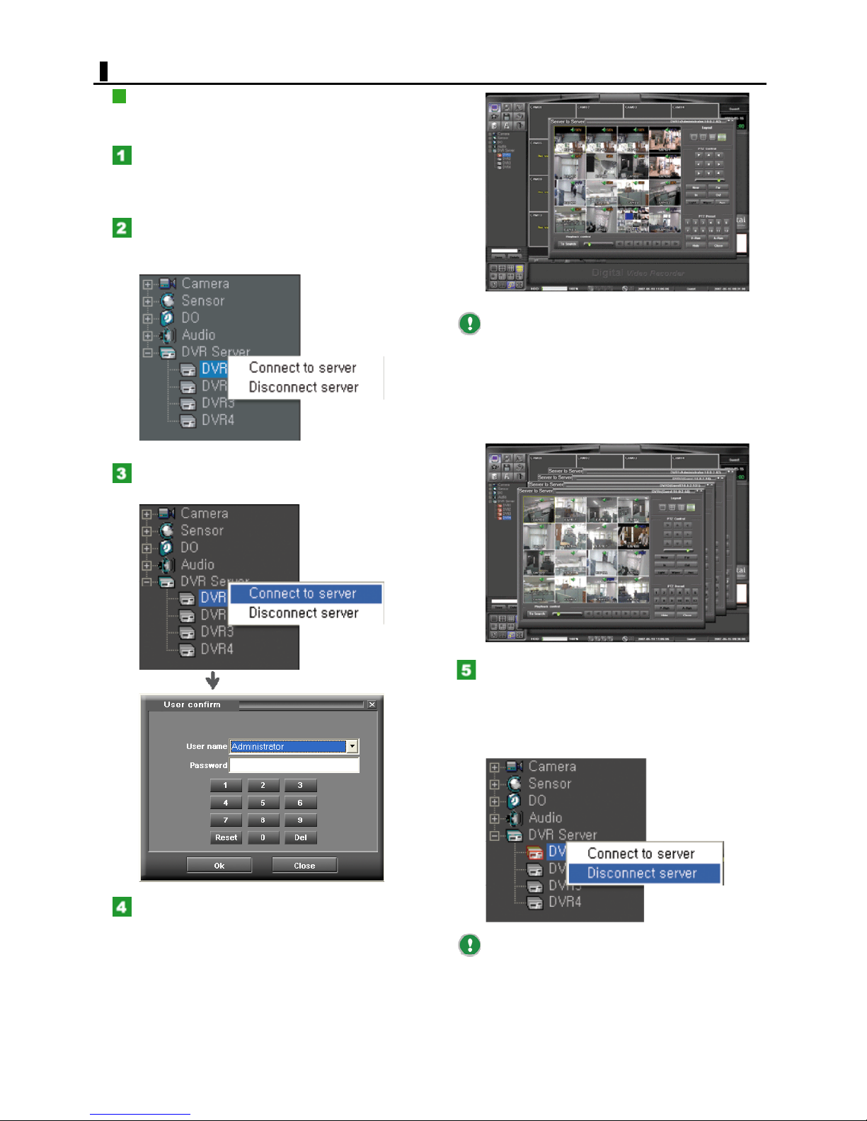
SERVER TO SERVER
CONNECTING TO A DVR
You can connect to DVR servers from the Camera
Information panel.
On the Camera Information panel, open the
"DVR Server" folder.
The currently registered DVR names appear below the
folder name.
Right-click the DVR server you want to connect
to.
The context menu appears.
Click [Connect to remote DVR].
The [Login] screen appears.
You can connect to up to four DVR servers
simultaneously by following the same procedure (Steps 2
to 4).
The [Server to Server] screens are in a cascading
display when two or more DVR servers are connected.
To switch the appearance of the cascading screen
display, click [DVR Server] in the ETC menu and then
select [Arrange all Server to Server window].
In the [User name] and [Password] fields,
select your user name and enter the password.
As soon as a connection to the DVR server is established,
the [Server to Server] screen appears.
On the Camera Information panel, the connected DVR
server is shown with a red border in the tree list.
To disconnect a DVR server
On
the Camera Information panel, select the DVR server
you want to disconnect in the tree list and, in the context
menu, select [Disconnect remote DVR].
The connection to the DVR server is disconnected and the
[Server to Server] screen closes.
To disconnect all the connected DVR servers
simultaneously, on the Camera Information panel, rightclick the "Server to Server" folder and, in the context
menu, select [Disconnect all remote DVR].
69
English
Page 70
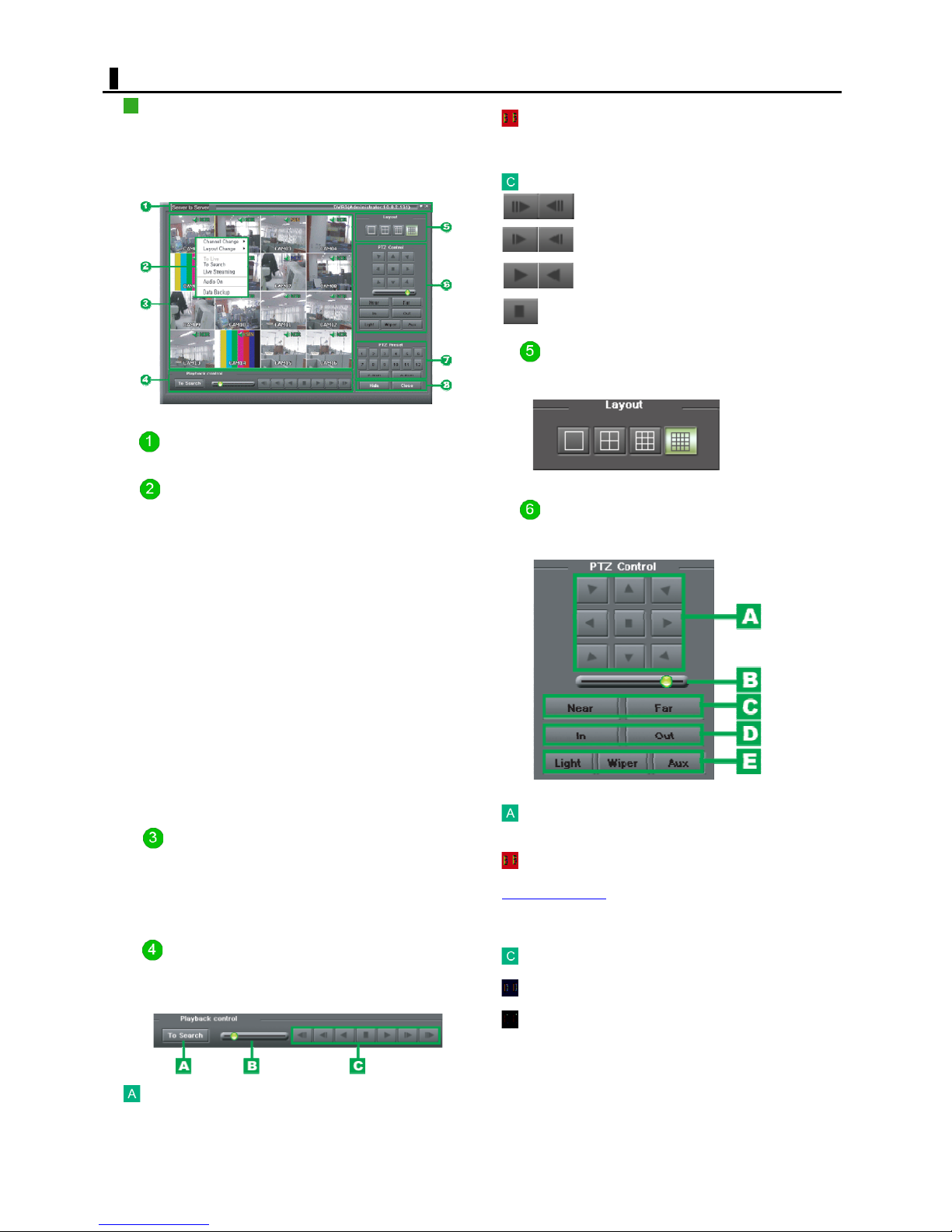
SERVER TO SERVER
COMPONENTS & FUNCTIONS
You can emulate other DVR servers on the network from a
DVR server.
If your target DVR server is connected to two or more
DVR servers and its screen is in a cascading display, bring
it to the front by clicking.
Title bar
Shows the DVR name, IP address, and user name.
Context menu
Right-clicking a video invokes the context menu, providing
the following menu commands.
Channel Change:
Selects the camera whose video you want to monitor on
the screen being selected.
Layout Change:
Switches among the four screen layouts (single-screen,
quad-screen, 9-screeen, and 16-screen).
To Live Mode:
Switches from the Search video to the Live video mode.
To Search Mode:
Switches from the Live video to the Search video mode.
Live Streaming:
Displays the live streaming video.
Audio On/Off:
Turns On/Off the audio output.
Data Backup:
Backs up the recording data to other recording media.
Perform data backup operation on the [Data Backup]
screen.
Video display area
Displays live or playback video. Each video is displayed
with information such as the camera title and the
recording mode.
In a multiple-screen layout, the screen you select by
clicking has a yellow border.
Playback speed indication
Shows the playback speed in six steps (0.5, 1.0, 2.0, 3.0,
4.0, and 5.0).
Playback buttons
: Go to the latest/oldest recorded data.
: Frame-forward/rewind
: Forward/reverse playback
Provides 2-step speed adjustment
: Stop
Layout
You can select the single-screen, quad-screen, 9-screen,
or 16-screen layout.
PTZ Control
In a single-screen layout, you can remotely operate a PTZ
camera.
Use this control to adjust the orientation of the
camera.
Use this slider bar to set how fast you can move
around on the image during panning/tilting or
screen shooting
The speed increases as you move the slider bar to the
right.
.
Playback control
The Playback control panel is used to play back the
searched video. To play back video, you need to select a
single channel.
To Search
Switches to the Search mode.
Use these buttons to adjust the focus.
Use these buttons to zoom in/out the video.
Use this button to adjust light/wiper/aux.
70
English
Page 71
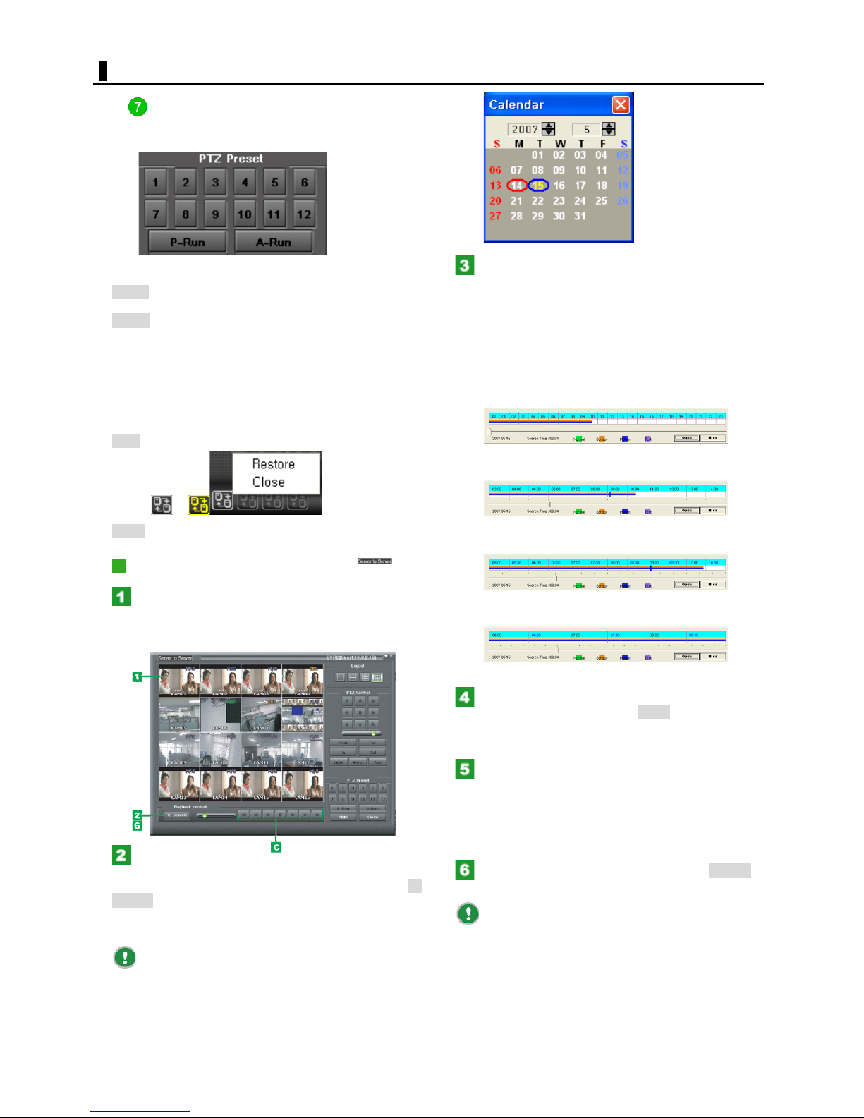
SERVER TO SERVER
PTZ Preset
Use the PTZ preset buttons to run the camera with
registered preset settings.
P-Run
A-Run Runs an auto panning pattern.
Other buttons
Hide
Sets the camera orientation to a registered
preset position.
Minimizes the [Server to Server] screen into an icon
in the status bar.
Minimizing the screen causes the color of the icon
to be changed from white to yellow.
Right-clicking these icons invokes the context menu
that shows the "Restore" and "Close" commands.
In the Calendar window, select the day on
which the video you want to play back was
recorded.
The time bars for the selected day appear.
Clicking the blue hour indication area sequentially changes
the time scale display as shown below.
You can scroll the time scale display forward and
backward by operating the slider bar.
24-hour display (1 hour ~ 24 graduations)
12-hour display (1 hour ~ 12 graduations)
to
Close Exits the emulation mode with the screen closed.
PLAYING BACK VIDEO
Click the video from the channel you want to
play back.
The screen selected by clicking is shown with an yellow
border.
On the [Playback Control] panel, click To
Search.
The Calendar window appears.
The label of the [To Search] button changes to [To Live].
You may also display the calendar by right-clicking
on the screen and, in the context menu, selecting [To
Search Mode].
6-hour display (30 minutes ~ 12 graduations)
3-hour display (30 minutes ~ 6 graduations)
Click the desired time bar to determine the
playback start point and, click Open.
The time bars disappear and the still image of the
specified start point appears.
Click the forward playback button on the
[Playback Control] panel.
The digital video recorder starts playing back the video
from the specified playback point.
To perform fast-forward, pause, and other playback
operations, use the corresponding playback buttons.
On the [Playback Control] panel, click To Live.
Now, the video display area shows again the live video.
You can also display the live video again by rightclicking the video and selecting [To Live Mode] in the
context menu.
If you select another channel to switch the
playback video during playback, the channel from which
you are playing back video currently will be switched
automatically to the live video.
71
English
Page 72
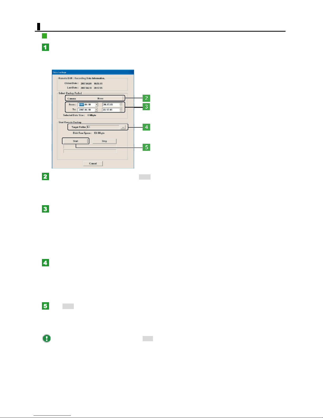
SERVER TO SERVER
BACKING UP DATA
Right-click the video from the channel you
want to back up and, in the context menu, select
[Data Backup].
The [Data backup] screen appears.
Click the [Camera] button (shown as None by
default) and specify the camera number for the
data you want to back up.
The [Camera] button now shows the selected camera
number.
In the [From] and [To] fields, specify the
recording date/time range of the data you want to
back up.
Set the recording date/time range to between the [Oldest
Data] and [Last Data] values shown in [Remote DVR:
Recording Data Information].
Setting a date/time range causes the digital video recorder
to display automatically the size of the recorded data to be
backed up.
In the [Target Folder] setting, select the
backup-destination folder.
The system now shows the space available in the backupdestination folder.
Confirm the total size of the files you selected does not
exceed the size of the available space in the backup
medium.
Click Start.
The system starts a backup, showing its progress as a
progress gauge.
When the backup process is finished, a dialog box opens,
showing the backup has been finished.
To cancel the backup process halfway, click Stop.
72
English
 Loading...