


DIGITAL VIDEO RECORDER
PLE Series
Server
Operation Manual
Please read these instructions and save this manual for future use
www.cascadiadvrt.com / (888) 421-0050
1

SAFETY INSTRUCTIONS
CAUTION:
TO REDUCE THE RISK OF ELECTRIC SHOCK,
DO NOT REMOVE COVER (OR BACK).
NO USER-SERVICEABLE PARTS INSIDE.
REFER SERVICING TO QUALIFIED SERVICE PERSONNEL.
THIS PRODUCT HAS MULTIPLE-RATED VOLTAGES.
ADJUST POWER INPUT SELECTOR SWITCH PROPERLY ON REAR OF UNIT BEFORE CONNECTING TO
THE POWER SUPPLY.
1) Read these instructions.
2) Keep these instructions.
3) Heed all warnings.
4) Follow all instructions.
5) Do not use this apparatus near water.
6) Clean only with dry cloth.
7) Do not block any ventilation openings. Install in accordance with the manufacturer's instructions.
8) Do not use near any heat sources such as radiators, heat registers, stoves, or other apparatus (including
amplifiers) that produce heat.
9) Do not defeat the safety purpose of the polarized or grounding-type plug. A polarized plug has two blades
with one wider than the other. A grounding-type plug has two blades and a third grounding prong. The wide
blade or the third prong are
provided for your safety. If the provided plug does not fit into your outlet, consult an electrician for
replacement of the obsolete outlet.
10) Protect the power cord from being walked on or pinched particularly at plugs, convenience receptacles
and the points where they exit from the apparatus.
11) Only use attachments/accessories specified by the manufacturer.
12) Use only with the cart, stand, tripod, bracket, or table specified by the manufacturer, or sold with the
apparatus.
13) Unplug this apparatus during lightning storms or when unused for long periods of time.
14) Refer all servicing to qualified service personnel. Servicing is required when the apparatus has been
damaged in any way, such as power-supply cord or plug is damaged, liquid has been spilled or objects fallen
into the apparatus, the apparatus has been exposed to rain or moisture, does not operat e normally, or has
been dropped.
NOTE: This equipment has been tested and found to comply with the limits for a Class A digital device, pursuant
to part 15 of the FCC rules These limits are designed to provide reasonable protection against harmful
interference when the equipment is operated in a commercial environment This equipment generates, uses, and
can radiate radio frequency energy and, if not installed and used in accordance with the instruction manual, may
cause harmful interference to radio communications Operation of this equipment in a residential area is likely to
cause harmful interference in which case the user will be required to correct the interference at his own expense
IMPORTANT The only way to disconnect power completely is to unplug the power cord
Make sure at least one end of the power cord is within easy reach so that you can unplug the computer when
you need to
CAUTION: DANGER OF EXPLOSION IF BATTERY IS INCORRECTLY REPLACED REPLACE ONLY WITH THE SAME
OR EQUIVALENT TYPE RECOMMENDED BY THE MANUFACTURER DISCARD USED BATTERIES ACCORDING TO
THE MANUFACTURER’S INSTRUCTIONS
WARNING:
To prevent fire or electric shock hazard, do not expose this appliance to rain or moisture. The apparatus shall
not be exposed to dripping or splashing and that no objects filled with liquids, such as vases, shall be placed
on the apparatus.
www.cascadiadvrt.com / (888) 421-0050
2

Table of Contents
51. LAYOUT ㅡㅡㅡㅡㅡㅡㅡㅡㅡㅡㅡㅡㅡㅡㅡㅡㅡㅡㅡㅡㅡㅡㅡㅡㅡㅡㅡㅡㅡㅡ
6FRONT VIEW ㅡㅡㅡㅡㅡㅡㅡㅡㅡㅡㅡㅡㅡㅡㅡㅡㅡㅡㅡㅡㅡㅡㅡㅡㅡ
7REAR VIEWㅡㅡㅡㅡㅡㅡㅡㅡㅡㅡㅡㅡㅡㅡㅡㅡㅡㅡㅡㅡㅡㅡㅡㅡ
82. DISPLAY ㅡㅡㅡㅡㅡㅡㅡㅡㅡㅡㅡㅡㅡㅡㅡㅡㅡㅡㅡㅡㅡㅡㅡㅡㅡㅡㅡㅡㅡ
9ALARM ㅡㅡㅡㅡㅡㅡㅡㅡㅡㅡㅡㅡㅡㅡㅡㅡㅡㅡㅡㅡㅡㅡㅡㅡ
9BACKUP ㅡㅡㅡㅡㅡㅡㅡㅡㅡㅡㅡㅡㅡㅡㅡㅡㅡㅡㅡㅡㅡㅡㅡㅡㅡㅡㅡㅡㅡ
9CASCADE ㅡㅡㅡㅡㅡㅡㅡㅡㅡㅡㅡㅡㅡㅡㅡㅡㅡㅡㅡㅡㅡㅡㅡ
9MAINTENANCE ㅡㅡㅡㅡㅡㅡㅡㅡㅡㅡㅡㅡㅡㅡㅡㅡㅡㅡㅡㅡㅡㅡㅡㅡㅡ
9SMART ㅡㅡㅡㅡㅡㅡㅡㅡㅡㅡㅡㅡㅡㅡㅡㅡㅡㅡㅡㅡㅡㅡㅡㅡㅡ
103. SETUP ㅡㅡㅡㅡㅡㅡㅡㅡㅡㅡㅡㅡㅡㅡㅡㅡㅡㅡㅡㅡㅡㅡㅡㅡㅡㅡㅡㅡㅡ
11RECORD ㅡㅡㅡㅡㅡㅡㅡㅡㅡㅡㅡㅡㅡㅡㅡㅡㅡㅡㅡㅡㅡㅡㅡㅡ
12EVENT ㅡㅡㅡㅡㅡㅡㅡㅡㅡㅡㅡㅡㅡㅡㅡㅡㅡㅡㅡㅡㅡㅡㅡㅡㅡㅡㅡㅡㅡ
13NETWORK ㅡㅡㅡㅡㅡㅡㅡㅡㅡㅡㅡㅡㅡㅡㅡㅡㅡㅡㅡㅡㅡㅡㅡ
14USER ㅡㅡㅡㅡㅡㅡㅡㅡㅡㅡㅡㅡㅡㅡㅡㅡㅡㅡㅡㅡㅡㅡㅡㅡㅡ
14CAMERA ㅡㅡㅡㅡㅡㅡㅡㅡㅡㅡㅡㅡㅡㅡㅡㅡㅡㅡㅡㅡㅡㅡㅡㅡㅡㅡ
15MAINTENANCE ㅡㅡㅡㅡㅡㅡㅡㅡㅡㅡㅡㅡㅡㅡㅡㅡㅡㅡㅡㅡㅡㅡㅡㅡㅡㅡㅡㅡ
16STORAGE ㅡㅡㅡㅡㅡㅡㅡㅡㅡㅡㅡㅡㅡㅡㅡㅡㅡㅡㅡㅡㅡㅡㅡ
17CASCADE ㅡㅡㅡㅡㅡㅡㅡㅡㅡㅡㅡㅡㅡㅡㅡㅡㅡㅡㅡㅡㅡㅡㅡㅡㅡ
184. QUICK USE 1 ㅡㅡㅡㅡㅡㅡㅡㅡㅡㅡㅡㅡㅡㅡㅡㅡㅡㅡㅡㅡㅡㅡㅡㅡㅡㅡㅡㅡㅡ
19GETTING STARTED ㅡㅡㅡㅡㅡㅡㅡㅡㅡㅡㅡㅡㅡㅡㅡㅡㅡㅡㅡㅡㅡㅡㅡㅡ
20TIME & DATE ADJUSTMENT ㅡㅡㅡㅡㅡㅡㅡㅡㅡㅡㅡㅡㅡㅡㅡㅡㅡㅡㅡㅡㅡㅡ
21DVR & REMOCON SETUP ㅡㅡㅡㅡㅡㅡㅡㅡㅡㅡㅡㅡㅡㅡㅡㅡㅡㅡㅡㅡㅡㅡㅡ
22HOW TO UPGRADE ㅡㅡㅡㅡㅡㅡㅡㅡㅡㅡㅡㅡㅡㅡㅡㅡㅡㅡㅡㅡㅡㅡㅡㅡㅡ
235. QUICK USE 2 ㅡㅡㅡㅡㅡㅡㅡㅡㅡㅡㅡㅡㅡㅡㅡㅡㅡㅡㅡㅡㅡㅡㅡㅡㅡㅡㅡㅡ
24FORCE RECORDING ㅡㅡㅡㅡㅡㅡㅡㅡㅡㅡㅡㅡㅡㅡㅡㅡㅡㅡㅡㅡㅡㅡㅡㅡ
25SCHEDULE RECORDING ㅡㅡㅡㅡㅡㅡㅡㅡㅡㅡㅡㅡㅡㅡㅡㅡㅡㅡㅡㅡㅡㅡㅡ
266. QUICK USE 3 ㅡㅡㅡㅡㅡㅡㅡㅡㅡㅡㅡㅡㅡㅡㅡㅡㅡㅡㅡㅡㅡㅡㅡㅡㅡㅡㅡㅡㅡ
27QUICK PLAYBACK ㅡㅡㅡㅡㅡㅡㅡㅡㅡㅡㅡㅡㅡㅡㅡㅡㅡㅡㅡㅡㅡㅡㅡㅡ
28NORMAL PLAYBACK ㅡㅡㅡㅡㅡㅡㅡㅡㅡㅡㅡㅡㅡㅡㅡㅡㅡㅡㅡㅡㅡㅡㅡㅡㅡ
www.cascadiadvrt.com / (888) 421-0050
29EVENT PLAYBACK ㅡㅡㅡㅡㅡㅡㅡㅡㅡㅡㅡㅡㅡㅡㅡㅡㅡㅡㅡㅡㅡㅡㅡㅡㅡㅡ
3

Table of Contents
307. QUICK USE 4 ㅡㅡㅡㅡㅡㅡㅡㅡㅡㅡㅡㅡㅡㅡㅡㅡㅡㅡㅡㅡㅡㅡㅡㅡㅡㅡㅡㅡㅡ
31STILL IAMGE SAVE ㅡㅡㅡㅡㅡㅡㅡㅡㅡㅡㅡㅡㅡㅡㅡㅡㅡㅡㅡㅡㅡㅡㅡㅡ
32BACKUP ㅡㅡㅡㅡㅡㅡㅡㅡㅡㅡㅡㅡㅡㅡㅡㅡㅡㅡㅡㅡㅡㅡㅡㅡ
338. QUICK USE 5 ㅡㅡㅡㅡㅡㅡㅡㅡㅡㅡㅡㅡㅡㅡㅡㅡㅡㅡㅡㅡㅡㅡㅡㅡㅡㅡㅡㅡㅡ
34IP SETTING ㅡㅡㅡㅡㅡㅡㅡㅡㅡㅡㅡㅡㅡㅡㅡㅡㅡㅡㅡㅡㅡㅡㅡㅡ
35DDNS SETTING/WEB VIEWER CONNECTING ㅡㅡㅡㅡㅡㅡㅡㅡㅡㅡㅡㅡㅡ
36E-MAIL SETTING & NOTIFICATOIN ㅡㅡㅡㅡㅡㅡㅡㅡㅡㅡㅡㅡㅡㅡㅡㅡㅡ
37USER P/W SETTING ㅡㅡㅡㅡㅡㅡㅡㅡㅡㅡㅡㅡㅡㅡㅡㅡㅡㅡㅡㅡㅡㅡㅡㅡ
389. QUICK USE 6 ㅡㅡㅡㅡㅡㅡㅡㅡㅡㅡㅡㅡㅡㅡㅡㅡㅡㅡㅡㅡㅡㅡㅡㅡㅡㅡㅡㅡㅡ
39PRESET & EVENT TRACKING ㅡㅡㅡㅡㅡㅡㅡㅡㅡㅡㅡㅡㅡㅡㅡㅡㅡㅡㅡㅡ
40MOTION, SENSOR & ALARM SETTING ㅡㅡㅡㅡㅡㅡㅡㅡㅡㅡㅡㅡㅡㅡㅡㅡ
41CONNECTING SENSOR ㅡㅡㅡㅡㅡㅡㅡㅡㅡㅡㅡㅡㅡㅡㅡㅡㅡㅡㅡㅡㅡㅡㅡ
42CONNECTING ALARM ㅡㅡㅡㅡㅡㅡㅡㅡㅡㅡㅡㅡㅡㅡㅡㅡㅡㅡㅡㅡㅡㅡㅡㅡ
43CONNECTING PTZ ㅡㅡㅡㅡㅡㅡㅡㅡㅡㅡㅡㅡㅡㅡㅡㅡㅡㅡㅡㅡㅡㅡㅡㅡ
44CONNECTING EXTERNAL STORAGE ㅡㅡㅡㅡㅡㅡㅡㅡㅡㅡㅡㅡㅡㅡㅡㅡㅡ
45INSTALLATION EXAMPLE 1 ㅡㅡㅡㅡㅡㅡㅡㅡㅡㅡㅡㅡㅡㅡㅡㅡㅡㅡㅡㅡㅡ
46INSTALLATION EXAMPLE 2 ㅡㅡㅡㅡㅡㅡㅡㅡㅡㅡㅡㅡㅡㅡㅡㅡㅡㅡㅡㅡㅡ
4710. CLIENT ㅡㅡㅡㅡㅡㅡㅡㅡㅡㅡㅡㅡㅡㅡㅡㅡㅡㅡㅡㅡㅡㅡㅡㅡㅡㅡㅡㅡㅡ
48INSTALLATION & CONONNECTION ㅡㅡㅡㅡㅡㅡㅡㅡㅡㅡㅡㅡㅡㅡㅡㅡㅡㅡ
5011. CLIENT ㅡㅡㅡㅡㅡㅡㅡㅡㅡㅡㅡㅡㅡㅡㅡㅡㅡㅡㅡㅡㅡㅡㅡㅡㅡㅡㅡㅡㅡ
51SINGLE SEARCH ㅡㅡㅡㅡㅡㅡㅡㅡㅡㅡㅡㅡㅡㅡㅡㅡㅡㅡㅡㅡㅡㅡㅡㅡㅡㅡ
52PTZ CONTROLㅡㅡㅡㅡㅡㅡㅡㅡㅡㅡㅡㅡㅡㅡㅡㅡㅡㅡㅡㅡㅡㅡㅡㅡㅡㅡ
52LIVE JPG, BMP, AVI SAVE ㅡㅡㅡㅡㅡㅡㅡㅡㅡㅡㅡㅡㅡㅡㅡㅡㅡㅡㅡㅡㅡㅡ
53CMS P/W SETTING ㅡㅡㅡㅡㅡㅡㅡㅡㅡㅡㅡㅡㅡㅡㅡㅡㅡㅡㅡㅡㅡㅡㅡㅡㅡ
54CONFIG FILE SAVE/LOAD ㅡㅡㅡㅡㅡㅡㅡㅡㅡㅡㅡㅡㅡㅡㅡㅡㅡㅡㅡㅡㅡㅡ
www.cascadiadvrt.com / (888) 421-0050
4
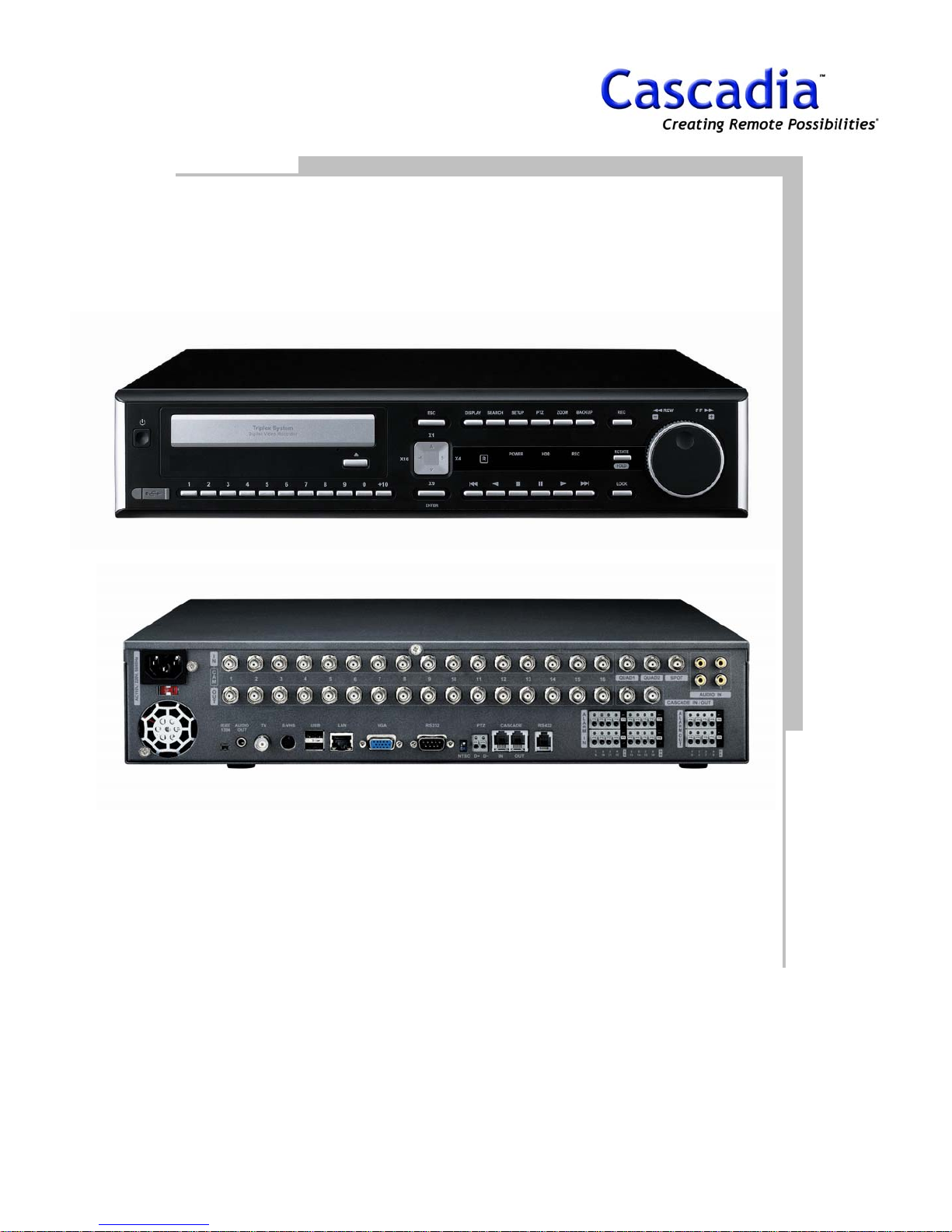
1. LAYOUT
FRONT VIEW
www.cascadiadvrt.com / (888) 421-0050
REAR VIEW
5
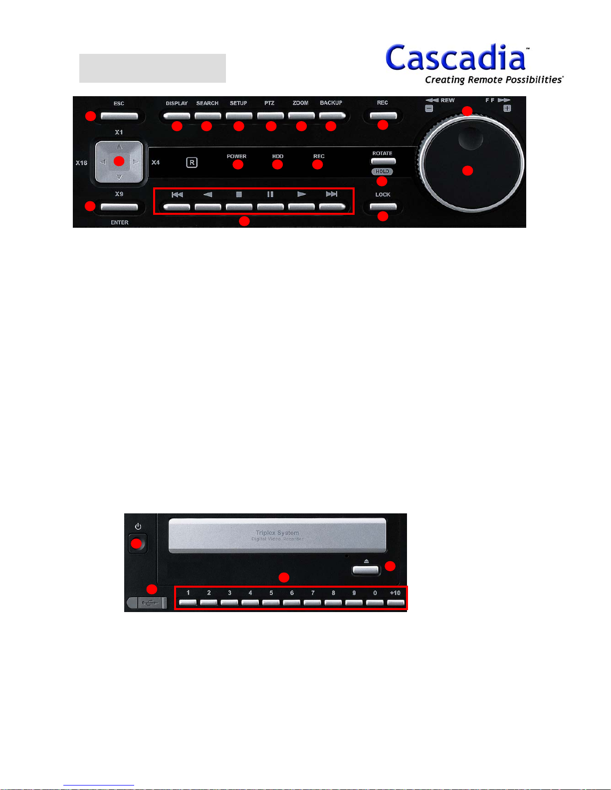
FRONT VIEW
15
13
14
1 2 3 4 5 6
16 17 18
10
1. Display Button
Shows the Display menu.
2. Search Button
Go to the Search menu.
3. Setup Button
Go to the Setup menu.
4. PTZ Button
Pan / tilt a selected camera.
5. Zoom Button
Zoom In/Out at 1CH Layout mode.
6. Backup Button
Go to the Backup menu.
7. REC Button
Record all cameras manually for emergency.
8. Rotate / Hold Button
Rotates the Live Camera Display.
Hold the search speed with Jog & Shuttle.
9. Lock Button
Locks the DVR.
10. Playback Button
Play, Pause, Reverse, Stop, End, Start.
12
7
11
8
9
11. Jog Dial
Play recorded images frame by frame when this
dial is rotated.
12. Shuttle Ring
Play fast when this dial is rotated.
13. Direction / Camera Layout Button
Move the cursor on the menu and shows camera
Layout.
UP: 1CH Layout,
Right: 4CH Layout
Down: 9CH Layout
Left: 16CH Layout
14. Enter Button
Determine the setting values.
15. ESC Button
Go back to the previous status.
16. Power LED
Light up when power is on.
17. HDD LED
Light up when built-in HDD is working.
18. REC LED
Light up when Manual recording is on.
19
20
19. Power Button
20. USB Port
Plug USB memory stick Upgrade
Software or Save Data. (USB 2.0)
www.cascadiadvrt.com / (888) 421-0050
22
21
21. Camera Button
Choose a camera you want to see.
22. CD/DVD Eject Button
6
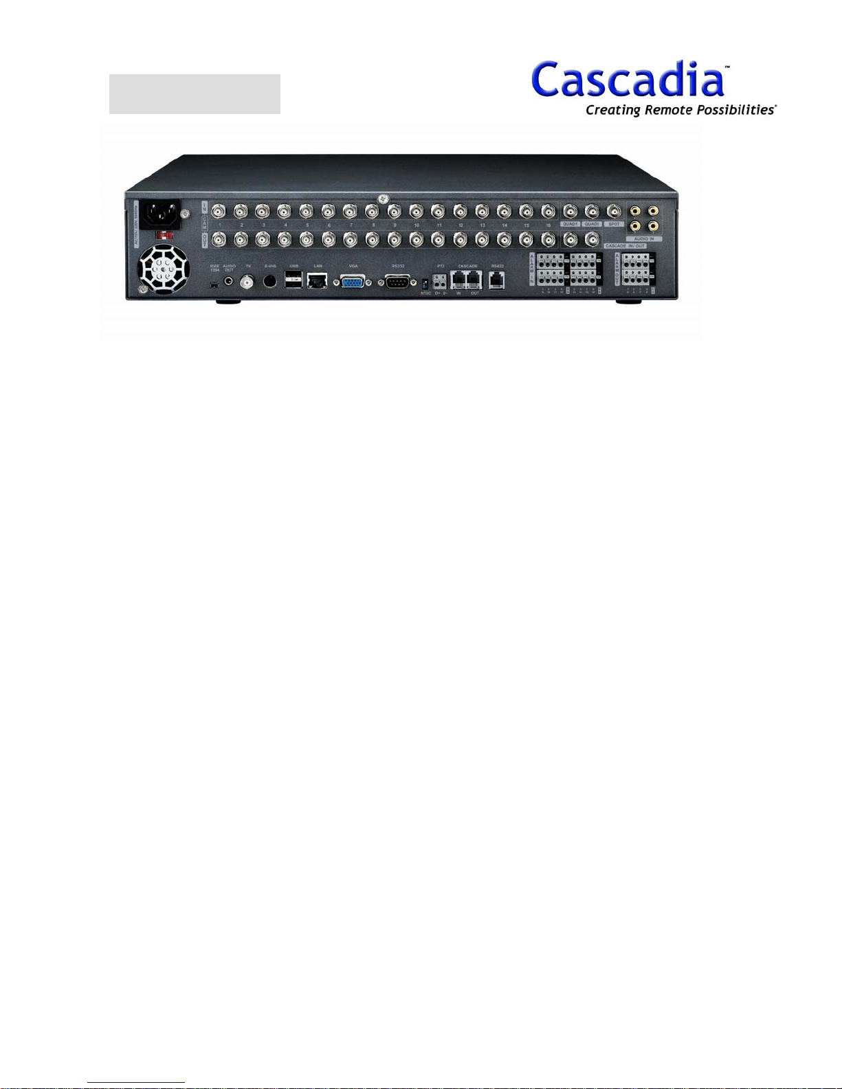
REAR VIEW
1. Camera Input Connectors
Connect cameras to these BNC connectors.
2. Camera Output Connectors (Loop Out)
These BNC connectors supply video signals looped
through the video input connectors.
3. Quad1
Show quad out (Fixed, Rotation) and a slave DVR
on an analogue monitor.
4. Quad2
Show quad out on analogue monitor.
(Fixed, Rotation)
5. Spot
Rotate a camera on an analogue monitor in order.
6. Cascade In/Out (BNC)
Connect with the CASCADE IN/OUT connector of
another DVR for image transmission when using
two or more units of DVR.
7. Audio Input Connectors (AUDIO IN 1 - 4)
Input audio signal supplied from an external
device such as a microphone amplifier.
8. IEEE1394
Connect to an external device like CD/DVD RW.
9. Audio Output Connector (AUDIO OUT)
Connect a speak for audio out.
13. USB (1.1)
Connect USB memory stick for Upgrade.
14. LAN (10/100BASE-T)
Connect this unit to a network compatible with
10BASET or 100BASE-Tx.
15. VGA
Connect a VGA monitor with this connector.
16. RS232 (SERIAL)
Connect a external device that supports this DSub 9-pin connector when controlling this unit.
17. PAL/NTSC
Chooses a PAL/NTSC video signal.
18. PTZ
Connect RS485 compatible combination
cameras with these port.
19. Cascade In/Out (RJ-11)
Connect with the cascade Out connector of
another DVR for command signal when using
two or more units of DVR.
20. RS422
Connect to Keypad.
21. ALARM IN
Connect an external device such as a sensor or
a door switch.
10. TV
Connect a monitor to BNC connector.
12. S-VHS
Connect a monitor to S-VHS connector.
www.cascadiadvrt.com / (888) 421-0050
22. ALARM OUT
Connect a control switch when controlling this
unit using an external device, or when
controlling an alarm device such as a buzzer or
a lamp.
7
2. DISPLAY
ALARM
BACKUP
CASCADE
MAINTENANCE
SMART
www.cascadiadvrt.com / (888) 421-0050
8
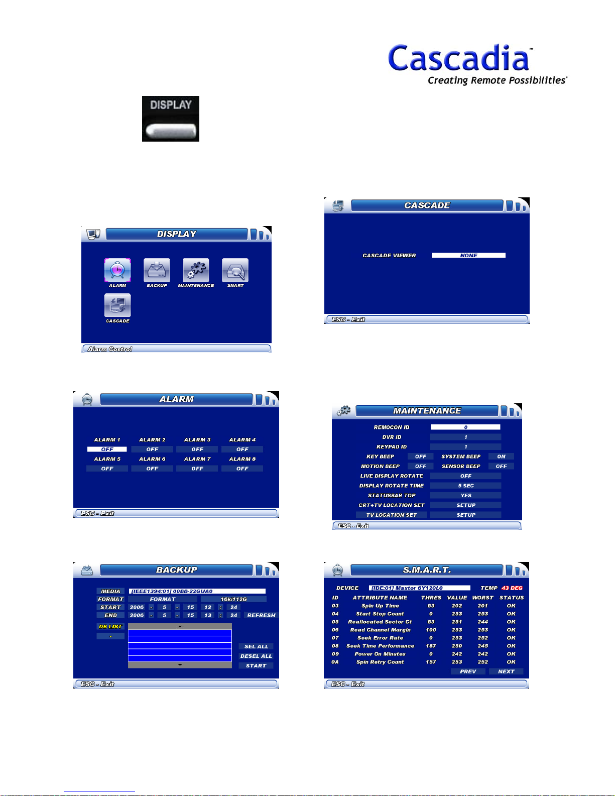
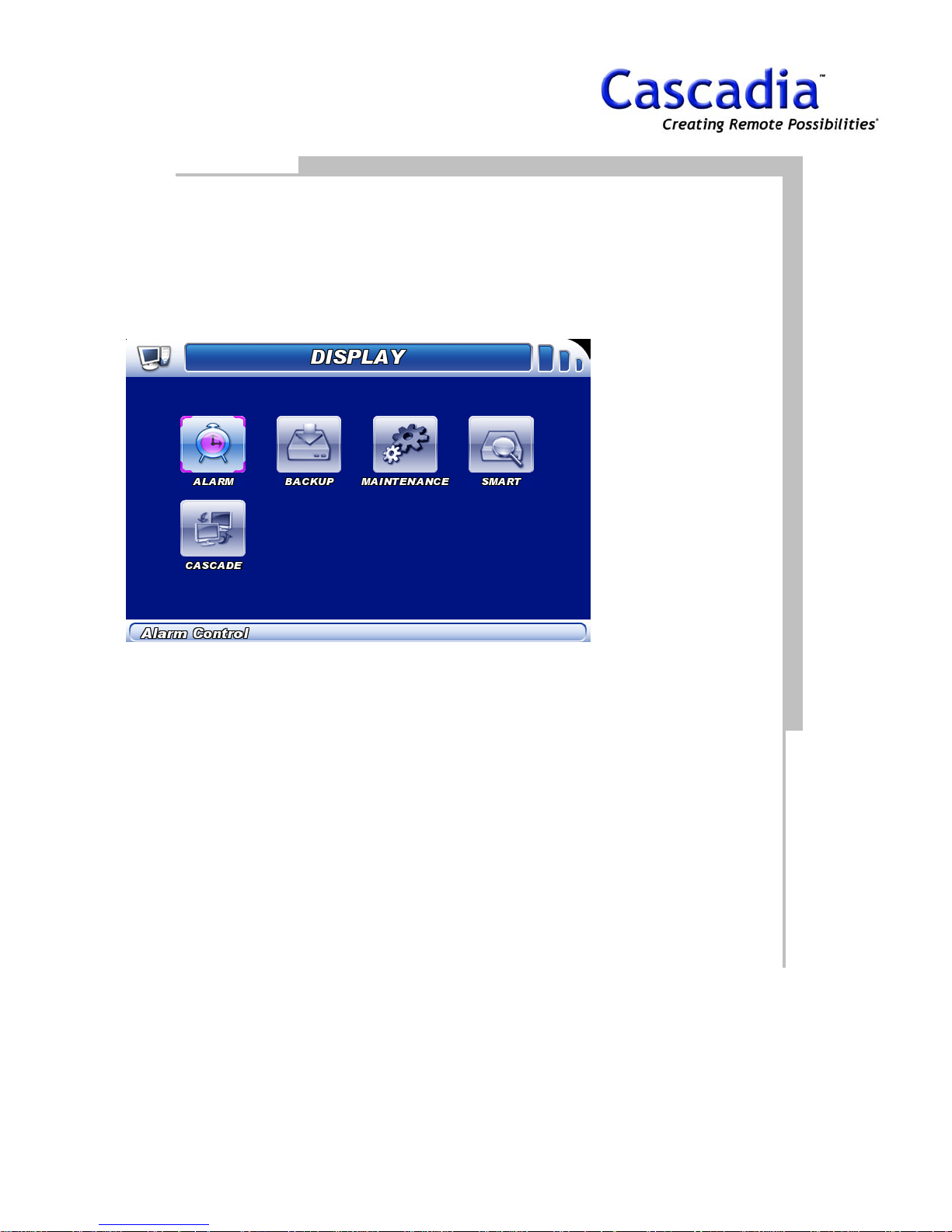
DISPLAY MENU
1. Press “DISPLAY”.
The SETUP MENU will be displayed. Move the
curser to highlight the “ALARM”, “BACKUP”,
MAINTENANCE”, “SMART” or “CASCADE”
Icon and press the “Enter” button to show the
appropriate information.
2. DISPLAY / ALARM
Turn On/Off alarm.
4. DISPLAY / CASCADE
Select the slave DVR that will show up on
Master DVR.
5. DISPLAY / MAINTENANCE
DVR ID = Set ID to communicate with Keyboard.
Keypad ID = Set ID to communicate with DVR.
Status Bar Top = Show the information bar
upward.
3. DISPLAY / BACKUP
Backup the recorded data with CD/DVD RW.
www.cascadiadvrt.com / (888) 421-0050
6. DISPLAY / SMART
Show HDD status. (Only information)
9

3. SETUP
RECORD
EVENT
NETWORK
USER
CAMERA
MAINTENANCE
STORAGE
CASCADE
www.cascadiadvrt.com / (888) 421-0050
10
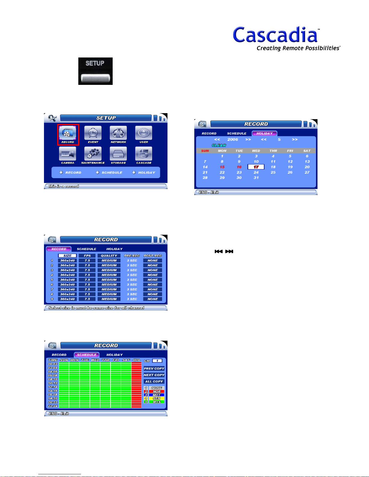
SETUP - RECORD MENU
1. Press “SETUP”.
The SETUP MENU will be displayed.
2. SETUP / RECORD / RECORD
Size = Resolution, Fps – Recording speed
Quality = Recording Quality
Pre & Post Rec = Pre & Post Recording time
4. SETUP / RECORD / HOLIDAY
Select a date to designate a holiday.
NOTE:
Item selection: Move the cursor using the
arrow buttons.
Change the setting: Press “Enter” button.
Selecting a submenu: Select a submenu
using buttons and press “Enter”
button.
3. SETUP / RECORD / SCHEDULE
Set recording schedule for each camera.
www.cascadiadvrt.com / (888) 421-0050
NOTE:
Default P/W is “1111111”.
11

SETUP - EVENT MENU
1. Press “SETUP”.
The SETUP MENU will be displayed.
2. SETUP / EVENT / MOTION
Region = Motion set area
Sensitivity = Motion sensitivity
4. SETUP / EVENT / ALARM
Duration = Set alarm duration time.
5. SETUP / EVENT / ALARM
SCHEDULE
Set alarm schedule for each alarm.
NOTE:
Alarm goes off when alarm schedule is set.
3. SETUP / EVENT / SENSOR
Type = Normal Close, Normal Open
Preset = Link sensor with Preset function of
Camera
www.cascadiadvrt.com / (888) 421-0050
NOTE:
Item selection: Move the cursor using the
arrow buttons.
Change the setting: Press “Enter” button.
Selecting a submenu: Select a submenu
using the buttons and press “Enter”
button.
NOTE:
Default P/W is “1111111”.
12
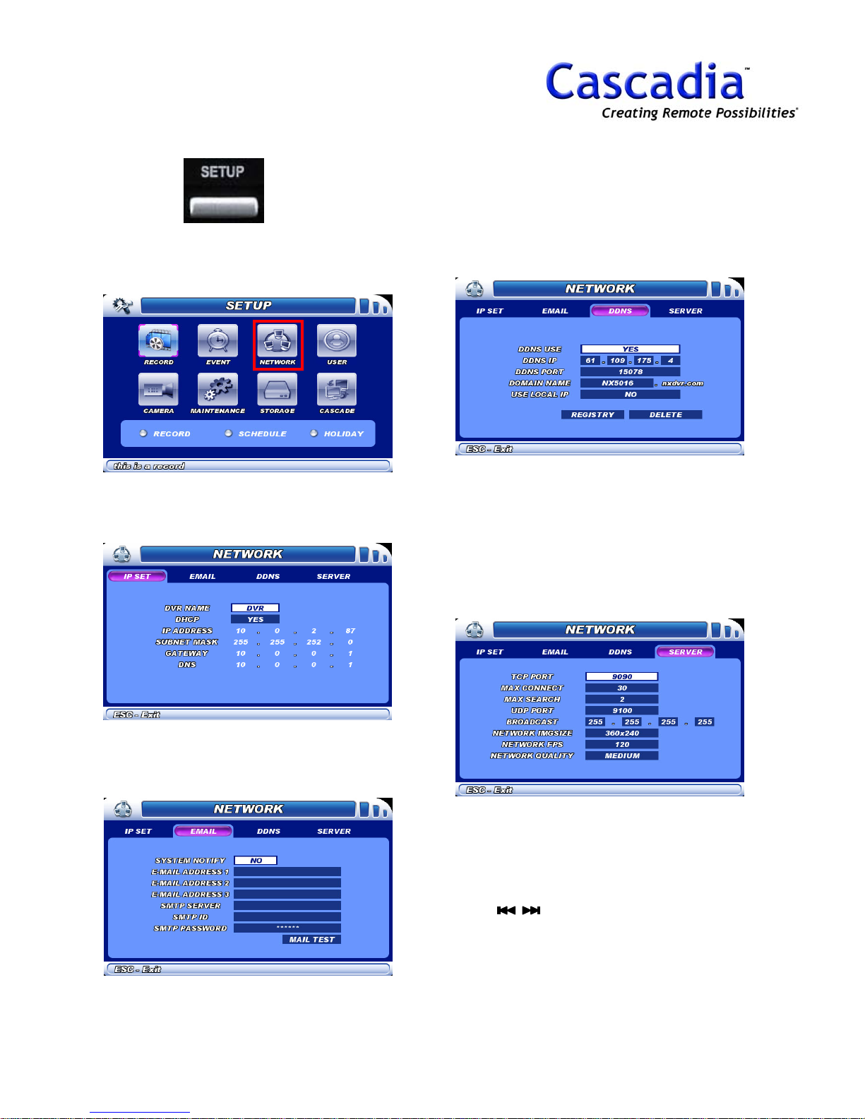
SETUP / NETWORK MENU
1. Press “SETUP”.
The SETUP MENU will be displayed.
2. SETUP / NETWORK / IP SET
DVR Name = Show DVR name in network S/W.
4. SETUP / NETWORK / DDNS
DDNS Use = Support Dynamic IP.
Domain Name = Type ID to use Dynamic IP.
Use Local IP = Connect DVR in same local
network like LAN for DDNS.
Registry = Register the DDNS information.
5. SETUP / NETWORK / SERVER
Max. Connect = Number of Live Connected Users
Max. Search = Number of Live Connected Users
Network IMG Size = Resolution for network
transmission.
Network Fps = Network transmission speed.
Network Quality = Image quality for network
transmission.
3. SETUP / NETWORK / EMAIL
System Notify = Send email when DVR has
problem.
www.cascadiadvrt.com / (888) 421-0050
NOTE:
Item selection: Move the cursor using the
arrow buttons.
Change the setting: Press “Enter” button.
Selecting a submenu: Select a submenu
using buttons and press “Enter” button.
NOTE:
Default P/W is “1111111”.
13
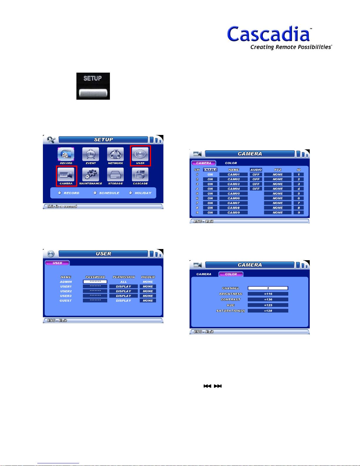
SETUP / USER & CAMERA
MENU
1. Press “SETUP”.
The SETUP MENU will be displayed.
2. SETUP / USER
Permission = Give user access permission.
Hidden = Show/Hide camera.
3. SETUP / CAMERA / CAMERA
Enable = Camera On/Off.
PTZ = Camera Protocol.
ID = Camera PTZ ID.
4. SETUP / CAMERA / COLOR
Channel = Camera No.
www.cascadiadvrt.com / (888) 421-0050
NOTE:
Item selection: Move the cursor using the
arrow buttons.
Change the setting: Press “Enter” button.
Selecting a submenu: Select a submenu
using buttons and press “Enter” button.
NOTE:
Default P/W is “1111111”.
14
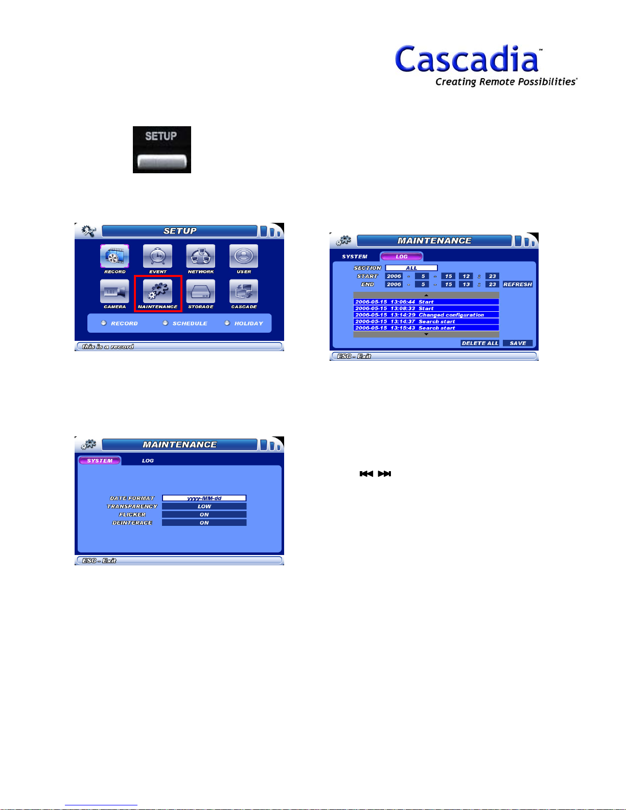
SETUP / MAINTENANCE
MENU
1. Press “SETUP”.
The SETUP MENU will be displayed.
2. SETUP / MAINTENANCE / SYSTEM
Transparency = Transparency of Menu Window.
Flicker = Flicker filter for TV Out.
Deinterlace = Anti aliasing Filter.
3. SETUP / MAINTENANCE / LOG
Show DVR working status.
NOTE:
Item selection: Move the cursor using the
arrow buttons.
Change the setting: Press “Enter” button.
Selecting a submenu: Select a submenu
using buttons and press “Enter” button.
NOTE:
Default P/W is “1111111”.
www.cascadiadvrt.com / (888) 421-0050
15
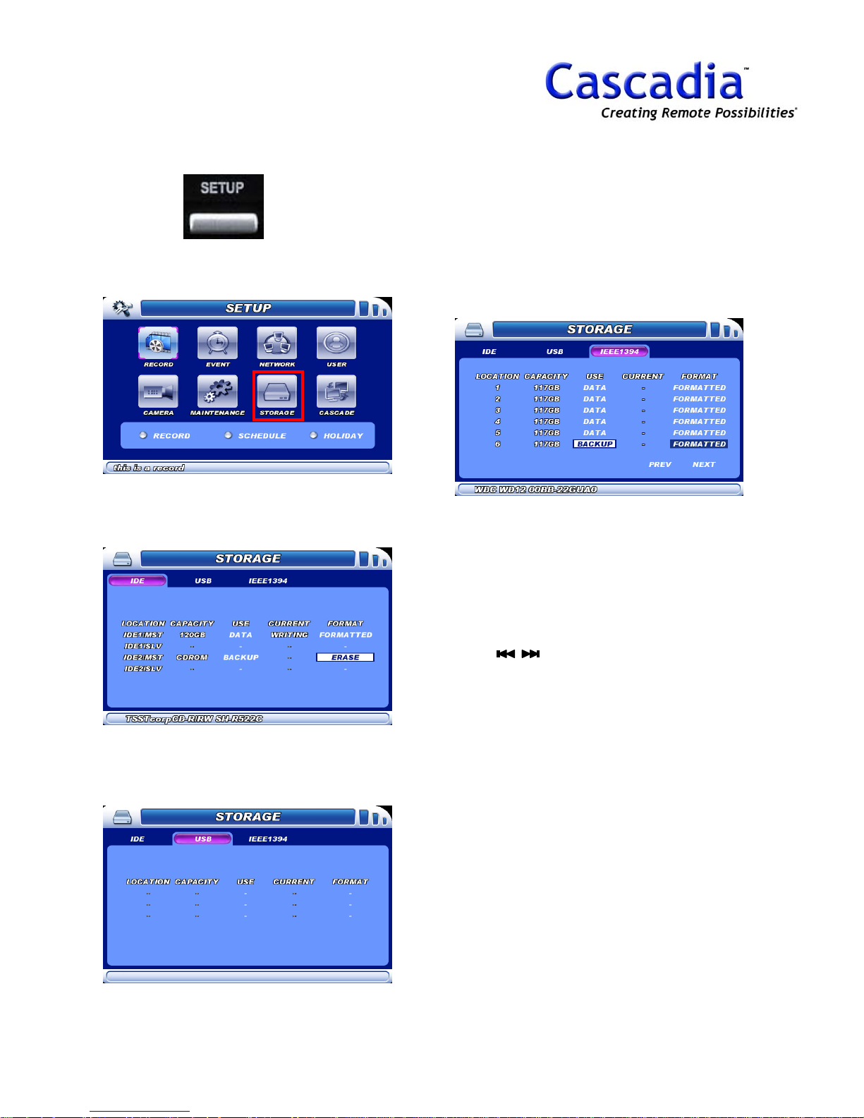
SETUP / STORAGE MENU
1. Press “SETUP”.
The SETUP MENU will be displayed.
2. SETUP / STORAGE / IDE
Show IDE device information.
Format = Format media on backup use.
4. SETUP / STORAGE / IEEE1394
Show IEEE1394 device information.
Format = Format media on backup use.
NOTE:
Item selection: Move the cursor using the
arrow buttons.
Change the setting: Press “Enter” button.
Selecting a submenu: Select a submenu
using buttons and press “Enter” button.
3. SETUP / STORAGE / USB
Show USB device information.
Format = Format media on backup use.
www.cascadiadvrt.com / (888) 421-0050
NOTE:
Default P/W is “1111111”.
16
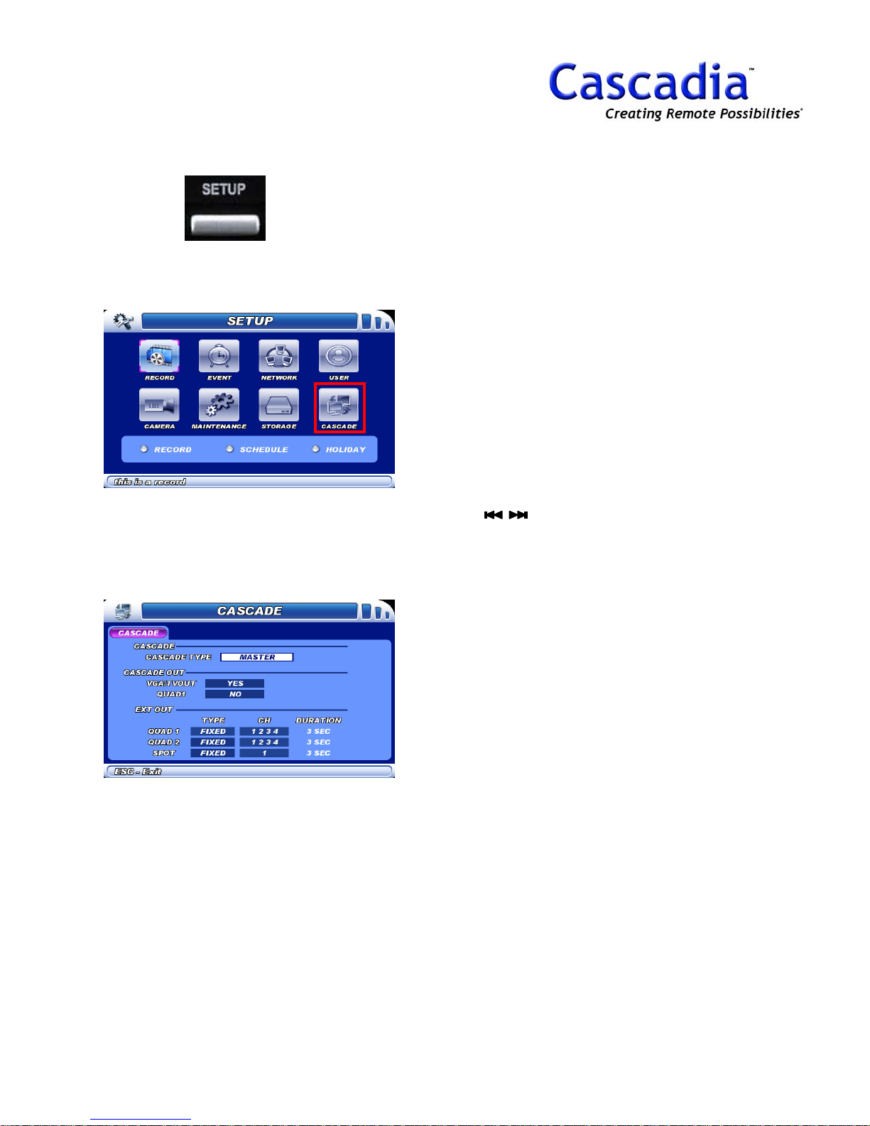
SETUP - CASCADE MENU
1. Press the SETUP button.
The SETUP MENU will be displayed.
2. SETUP / CASCADE / CASCADE
Cascade Type = Set DVR as Master or Slave.
VGA/TV Out = Show slave DVR to VGA/TV out.
Quad1 = Show slave DVR to Quad1 out.
NOTE:
Item selection: Move the cursor using the
arrow buttons.
Change the setting: Press “Enter” button.
Selecting a submenu: Select a submenu
using buttons and press “Enter” button.
NOTE:
Default P/W is “1111111”.
www.cascadiadvrt.com / (888) 421-0050
17

4. QUICK USE
1
GETTING STARTED
TIME & DATE ADJUSTMENT
DVR & REMOCON ID SETUP
HOW TO UPGRADE
www.cascadiadvrt.com / (888) 421-0050
18

GETTING STARTED
1. Insert the “Power Plug” to an outlet
2. Turn the power button “ON”.
Boot up Window will be displayed like the below.
NOTE:
Boot up window will only be displayed when on
Factory default
3. Select “Language”, “GMT”,
“Date/Time”.
4. Format the HDD.
NOTE:
Standard: Max. 4 HDDs will be available inside.
CD/DVD (Option): Max. 2 HDDs will be available inside
5. Go to Live mode.
Show the “Loading……” and go to Live mode.
.
www.cascadiadvrt.com / (888) 421-0050
19

TIME&DATE
ADJUSTMENT
It is recommended to check the clock before
installation and put the clock right if it shows
the wrong time.
1. Press “SETUP”.
The SETUP MENU will be displayed on the
monitor.
4. Move the cursor to “Date & Time”.
Change the GMT and then time & date.
5. Press “OK” button.
Press “OK” button to save the changed time.
6. Press “ESC” button to go back to
LIVE mode.
DVR will restart and the below warning window
will show up.
2. Press “Setup” button again and
No.1,2,3 and P/W window will show
up.
Input the P/W and A/S MENU will be displayed
on the monitor.
www.cascadiadvrt.com / (888) 421-0050
7. Press “OK” button.
Press “OK” to adopt the changed time and
Backup window will show up.
NOTE:
The above warning message is to confirm the
changed time.
Select “OK” to confirm the time.
Select “Cancel” to ignore the changed time.
8. Press “ESC” button to exit without
Backup.
Press “ESC” button to exit without Backup
when Backup window shows up.
And then the Live image will be displayed and
the Selected time & date will be applied on the
information bar.
20

DVR & REMOTE
CONTROLLER ID SETUP
ID Setting of DVR
Set remote controller ID as described below.
1. Press “DISPLAY”.
The DISPLAY MENU will be displayed.
ID Setting of Remote Controller
Set remote controller ID as described below.
1. Face controller to IR receiver of
DVR.
2. Holding the “ID” button of the
remote controller
Power LED will twinkle.
3. Press No. of controller ID you set
on DVR.
.
2. Go to DISPLAY / MAINTENANCE
Select a Remocon ID No.
3. Press “ESC” button to save and exit.
4. Press “Enter” button.
Power LED will stop twinkle.
NOTE:
When “Remocon ID” of DVR matches the
remote controller ID, the LED on the front of
the POWER stops twinkling.
www.cascadiadvrt.com / (888) 421-0050
21

HOW TO UPGRADE
Please perform the following instructions.
1. Press “SETUP”.
The SETUP MENU will be displayed on the
monitor.
3. Plug in USB memory stick with
UPGRADE file to DVR.
4. Go to “UPGRADE”.
Upgrade window will show up.
5. Press “Upgrade” button.
DVR will restart and go to live mode.
NOTE:
If DVR hangs at the screen of “LOADING…” for
10 minutes after upgrade, please contact your
local distributor.
2. Press “Setup” button again and
No.1,2,3 and P/W window will be
show up.
Input the P/W and A/S MENU will be displayed
on the monitor.
www.cascadiadvrt.com / (888) 421-0050
22

5. QUICK USE
2
FORCE RECORDING
SCHEDULE RECORDING
www.cascadiadvrt.com / (888) 421-0050
23

MANUAL RECORDING
1. Start “Manual Recording”.
Press the “REC” button to start manual recording.
The indicator of REC will light and recording will start.
Images from all the connected cameras will be
recorded manually with the current recording rate.
NOTE:
When manual recording is performed, schedule
recording will not be performed until manual recording
stops.
2. Stop “Manual Recording”.
Press the “REC” button again to stop recording.
The indicator on the button will go off and recording
will stop.
Images from all the connected cameras will be
recorded with the scheduled recording rate as schedule.
www.cascadiadvrt.com / (888) 421-0050
24

SCHEDULE RECORDING
Do the followings to do schedule recording.
1. Press “SETUP”.
The SETUP MENU will be displayed on the
monitor.
NOTE:
Item selection: Move the cursor using the
arrow buttons.
Change the setting: Press “Enter” button.
Selecting a submenu: Select a submenu
using buttons and press “Enter” button.
3. Move to “SCHEDULE” and Press
“Enter” button.
The SCHEDULE MENU will be displayed.
How to set schedule
1.Choose CH (Camera)
2.Move the cursor on the time table
3.Press “No.” for Record like the following.
1 – None,
2 – NORMAL,
3 – MOTION,
4 – SENSOR,
5 – MOTION+SENSOR
4.Press “ESC” to change the CH (Camera)
2. Move the cursor to “RECORD” and
Press “Enter” button.
The RECORD MENU will be displayed on the
monitor.
SIZE = Resolution
FPS = Recording rate
Quality = Image Quality
PRE = Pre-Record
POST = Post - Record
www.cascadiadvrt.com / (888) 421-0050
4. Press “ESC” button again to “Save
& Exit”.
The Live image will be displayed and recording
status will be displayed as circle on the right
corner of each camera.
25

6. QUICK USE
3
QUICK PLAYBACK
NORMAL PLAYBCK
EVENT SEARCH
www.cascadiadvrt.com / (888) 421-0050
26

QUICK SEARCH
It is possible to play recorded image without stopping recording.
Playback image will be displayed on the monitor.
1. Press “Playback” button.
Go to search mode directly.
NOTE:
It shows same camera layout of Display mode.
To change the camera layout, press a direction
button for 1CH, 4CH, 9CH, 16CH.
1CH – UP button
4CH – RIGHT button
9CH – DOWN button
16CH – LEFT button
www.cascadiadvrt.com / (888) 421-0050
27

NORMAL SEARCH
There are two ways to go to search mode and
play it.
- one is Normal Search.
- the other is Event Search.
1. Press “SEARCH”.
The SEARCH menu will be displayed on the
monitor.
3. Move the cursor to Date and Press
“Enter” button.
Data map will be displayed for 24 hours.
NOTE:
Date with recorded data will be marked in
yellow.
4. Select the start time and Press
“Enter” button.
Playback image will be displayed.
2. Press the CALENDAR button.
The CALENDAR will be displayed on the
monitor.
NOTE:
It could take a few minutes to bring out the
recorded data according to HDD capacity.
www.cascadiadvrt.com / (888) 421-0050
NOTE:
How to move the time indicator.
Use the arrow buttons and jog dial.
How to change the screen layout.
Press Direction buttons of1-4-9-16 CH screen
.
layout
28

EVENT SEARCH
There are two ways to go to search mode and
play it.
- one is Quick Search.
- the other is Normal Search.
1. Press “SEARCH”.
The SEARCH menu will be displayed on the
monitor.
3. Select “Start” & “End” time.
4. Select “Recording Type” & “Cam
No.”.
2. Press the EVENT button.
The EVENT menu will be displayed on the
monitor.
NOTE:
EVENT search will help user to search recorded
data as recording type and cam no.
www.cascadiadvrt.com / (888) 421-0050
5. Select the list and Press “Enter”
button.
Playback image will be displayed. Playback
image will be displayed on the monitor
NOTE:
Please press “Lock” button to hide the backup
window while doing backup process.
29
.

7. QUICK USE
4
STILL IMAGE SAVE
BACKUP
www.cascadiadvrt.com / (888) 421-0050
30

STILL IMAGE
SAVE
PNG file save is only available at 1 CH screen
layout at search.
1. Plug in USB memory stick to DVR.
2. Press “SEARCH”.
The SEARCH menu will be displayed on the
monitor.
3. Press the CALENDAR button.
The CALENDAR will be displayed on the monitor.
5. Select 1CH screen layout.
The selected CH will be displayed on the
monitor.
6. Press “BACKUP” button.
Save the still image as PNG file format.
4. Go to Playback Mode of Search.
www.cascadiadvrt.com / (888) 421-0050
31

BACKUP
To copy recorded images to the CD-RW or DVD
disk, formatting (initializing) the disk is required in
advance.
1. Press “Backup”.
The BACKUP MENU will be displayed.
2. Move the cursor to Backup Media
and Press “Enter’ button.
Select Backup device like CD-RW, DVD.
NOTE:
For external Backup media, it supports
IEEE1394 not USB 2.0.
3. Move the cursor to “FORMAT” and
Press “Enter” button.
During formatting, the status window will be
displayed. The status window will be closed
automatically when completing formatting.
4. Set “Start” & “End” time and Press
“REFRESH” button.
DATA will be shown on the DB list.
5. Press “START” button
Show backup progressing window.
NOTE:
All data on the disk will be deleted if formatted
(initialized).
It is impossible to recover the deleted images
on CD/DVD media
.
www.cascadiadvrt.com / (888) 421-0050
32

8. QUICK USE
5
IP SETTING
DDNS SETTING/WEB VIEWER
CONNECTING
E-MAIL SETTING & NOTIFICATION
USER P/W SETTING
www.cascadiadvrt.com / (888) 421-0050
33

IP SETTING
1. Press “SETUP” .
The SETUP MENU will be displayed on the
monitor
2. Go to “NETWORK”.
The IP SETTING MENU will be displayed on the
monitor.
.
DHCP
Select YES or NO whether or not to use the
DHCP server. When obtaining IP addresses,
Subnet mask, and a Gateway address from the
DHCP server, set to YES.
If not, se to NO and enter those addresses
manually.
YES: Uses DHCP server. (LAN)
NO: Uses Static IP address.
NOTE:
Pleas ask your network manager when you are
not sure of DHCP or IP address.
NOTE:
Item selection: Move the cursor using the
arrow buttons.
Change the setting: Press “Enter” button.
Selecting a submenu: Select a submenu
using buttons and press “Enter” button.
NOTE:
Default P/W is “1111111”.
3. Set “DHCP” to “Yes” for LAN use or
Set “DHCP” to “No” for static IP use.
Type the network information.
www.cascadiadvrt.com / (888) 421-0050
34

DDNS & WEBVIEWER
CONNECTING
Perform the following basic network settings.
1. Press “SETUP”.
The SETUP MENU will be displayed on the monitor.
2. Go to “Network” / “DDNS”
The DDNS MENU will be displayed on the monitor.
DDNS IP
DDNS IP is the default Server IP for DDNS.
DDNS Port
Show the Port No. in DDNS.
Use Local IP
Set “Use Local IP” to “YES” when try to
connect DVR using DDNS in the same local
network like LAN.
How to register DDNS ID on DDNS server.
:8080
If the registered domain name is “home”,
please type like the below example.
Ex) http://home.pledvr.com:8080
NOTE:
DVR is using 9090, TCP Port and 9100, UDP
Port as default.
1. Enable “DDNS USE” to “YES”
2. Type the Domain name.
3. Press “REGISTRY” button to register the
domain name on DDNS Server.
How to use web viewer with Internet
Explorer.
1. Run “Internet Explorer”.
2. Type the registered domain name of DDNS.
Refer to the below example figure.
3. Select “User ID” and Input “P/W”.
4. Click “Connect” button.
www.cascadiadvrt.com / (888) 421-0050
35

E-MAIL SETTING &
NOTIFICATION
1. Press “SETUP”.
The SETUP MENU will be displayed.
2. Go to “Network” / “E-Mail”.
The E-Mail MENU will be displayed.
NOTE:
First the E-Mail setting should be done to send
System Warning and DVR Start.
NOTE:
Item selection: Move the cursor using the
arrow buttons.
Change the setting: Press “Enter” button.
Selecting a submenu: Select a submenu
using buttons and press “Enter” button.
NOTE:
Default P/W is “1111111”.
E-MAIL Address
Enter the e-mail address for transmission.
(System warning)
SMTP SERVER
Enter SMTP mail sever name.
SMTP ID
Enter the ID when SMTP sever requires.
SMTP Password
Enter the P/W when SMTP sever requires.
System Notify
Select ON or OFF whether or not to use the
system notification.
www.cascadiadvrt.com / (888) 421-0050
36

USER PASSWORD SETTING
Perform the following settings.
1. Press the SETUP button.
The SETUP MENU will be displayed on the
monitor.
NOTE:
Set USER Password, Permission and Hidden
camera.
Each user can select camera to be hidden on
live and search mode.
2. Go to “USER”.
The USER MENU will be displayed on the
monitor.
3. Set P/W, Permission, Hidden
camera per user.
NOTE:
Default P/W is “1111111”.
www.cascadiadvrt.com / (888) 421-0050
37

9. QUICK USE
6
PRESET & SENSOR TRACKING
MOTION, SENSOR & ALARM
SETTING
CONNECTING SENSOR
CONNECTING ALARM
CONNECTIONG PTZ
ADDING EXTERNAL STORAGE
www.cascadiadvrt.com / (888) 421-0050
38

PRESET SETTING & SENSOR
TRACKING
1. Press the “SETUP” & “CAMERA”.
The CAMERA MENU will be displayed and choose a
camera protocol.
2. Go back to Live Mode and choose a
camera for PTZ.
Set
Save the camera movement as Preset.
Move
Move the selected Preset No.
Clear
Delete the selected Preset No.
Tour Start
Start all Preset No. in order with the Duration
time.
6. Select “Preset No.” and Press “SET”
button.
Save the camera movement as the selected Preset
No.
NOTE:
Max. Preset No. will be up to No.12.
8. Go to SETUP / EVENT / SENSOR.
The SENSOR MENU will be displayed.
3. Press PTZ button.
The PTZ MENU will be displayed.
4. Press “Pan/Tilt” and the following
menu will be displayed.
Move, Zoom, Focus, Iris, Auto Pan, Light,
Speed, OSD Menu
5. Press “Setup” and move the camera
with the direction button.
Press “ESC” button to exit the Pan/Tilt mode.
9. Move the cursor to “Preset” and
Enable to “YES”.
Select preset No. for each camera.
10. Select camera and Preset No.
NOTE:
Sensor Tracking is only available on SENSOR.
www.cascadiadvrt.com / (888) 421-0050
39

MOTION, SENSOR &
ALARM SETTING
1. Press “SETUP”.
The SETUP MENU will be displayed.
2. Go to EVENT / MOTION
Set a motion detecting area.
5. Move the cursor to “ALARM” and
Press “Enter” button.
The ALARM SELECTION will be displayed and
select Alarm for the sensor of Camera.
6. Go to EVENT / ALARM
Select a alarm type. (N/C, N/O)
7. Move the cursor to “DURATION”
and select duration time.
Select alarm type (N/C, N/O) and select alarm
duration time.
3. Move the cursor to “ALARM” and
select Alarm No.
The ALARM SELECTION will be displayed and
select Alarm No. for the Motion of Camera.
4. Go to EVENT / SENSOR
Select a sensor type. (N/C, N/O)
8. Go to EVENT / A.SCHEDULE
ALARM MENU will be displayed.
9. Set the Schedule for each Alarm.
Select alarm schedule for each alarm.
NOTE:
Press “ESC” button to select other alarm No.
after setting alarm schedule.
Make sure that alarm schedule is set for alarm.
www.cascadiadvrt.com / (888) 421-0050
40

CONNECTING SENSOR
How to Insert/remove wires
For inserting into or removing wires from the
TERMINAL BLOCK, push the lever as shown in
the figure.
1. Press “SETUP”.
The SETUP MENU will be displayed.
2. Go to EVENT / SENSOR
The SENSOR MENU will be displayed.
Specification
Input Circuits No. : 16 TTL level compatible
input
Input Type : N/C, N/O
Sensor : Dry contact sensor
Connection : Connect the stripped wires to
the terminal block.
Valid Input Pulse Duration : MIN. 500ms.
Output Currents : Typical DC6mA.
The sensor input has the specifications and
normal operating conditions as described below.
How to connect Sensor Input
For connection of sensor inputs S1 ~ S16, see
the figure below. The figure below is an
example of dry contact sensor connection.
2. Move the cursor to “TYPE” and
Select “N/C or N/O”.
NOTE:
Wiring Terminating Wires
The wires for the TERMINAL BLOCK are
terminated as described below. Strip the outer
covering to the defined length (8~10mm).
Suitable wires are AWG 20 ~ 26.
www.cascadiadvrt.com / (888) 421-0050
41
+-
SENSOR
Exterior
Power

CONNECTING ALARM
(RELAY OUT)
1. Press the SETUP button.
The SETUP MENU will be displayed.
2. Go to EVENT / ALARM
The ALARM MENU will be displayed.
The alarm output has the specifications and
normal operating conditions as described
below.
Specification
Output Circuits No. : Automatic output of
4(8) relays.
Output Method : Dry contact
Connection : Connect the stripped wires to
the terminal block.
DC : 24V DC, 1.25A, 30W
125V DC, 0.24A, 30W
AC : 125V AC, 0.5A, 62.5VA
250V AC, 0.25A, 62.5VA
For connection of R1 ~ R4(8) outputs, see the
figure below. The figure below is an example
for connecting the warning lamp.
3. Move the cursor to “TYPE” and
Select “N/C” OR “N/O”.
NOTE:
Wiring Terminating Wires
The wires for the TERMINAL BLOCK are
terminated as described below. Strip the outer
covering to the defined length (8~10mm).
Suitable wires are AWG 20 ~ 26.
www.cascadiadvrt.com / (888) 421-0050
Exterior Power
ALARM
42

CONNECTING PTZ
1. PTZ Connection with DVR.
Please refer to the below figure.
PTZ
D+ D-
PAN/TILT (1)
R
R
X
X
-
+
PAN/TILT (3)
R
R
X
X
-
+
T
X
+
T
X
+
T
X
-
T
X
-
PAN/TILT (2)
R
R
X
X
-
+
PAN/TILT (4)
R
R
X
X
-
+
T
X
+
T
X
+
T
X
-
T
X
-
www.cascadiadvrt.com / (888) 421-0050
43

EXTERNAL STORAGE
CONNECTING
1. Connecting EHD1500 to DVR
Tera1500A is connected to the IEEE1394 port
on the DVR. Please set up as follows.
IEEE1394 Port of DVR
There are two IEEE1394 ports at the rear of
EHD1500. One is for connection to DVR (Port
IN), the other for expansion (Port Out).
Rear View of EHD1500
EHD1500 HDD Capacity
6HDDs(500GB*6) – 3TB
NOTE:
Power ON and OFF DVR and thenEHD1500 like
the below order.
Power ON: EHD1500 to DVR.
Power OFF: DVR to EHD1500.
Connect the EHD1500 Port IN to the IEEE1394
port of DVR, using an IEEE1394 cable as above.
Cable
Connection with EHD1500
www.cascadiadvrt.com / (888) 421-0050
44
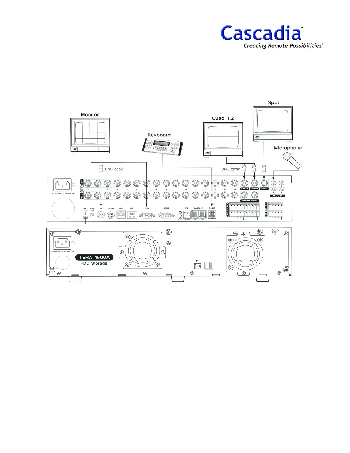
INSTALLATION EXAMPLE 1
INSTALLATION EXAMPLE 1
The below is the basic installation with Tera1500A and Keyboard.
www.cascadiadvrt.com / (888) 421-0050
45

INSTALLATION EXAMPLE 2
INSTALLATION EXAMPLE 2
The below is advanced installation with 5 DVRs and Keyboard.
www.cascadiadvrt.com / (888) 421-0050
46

10. CLIENT
INSTALLATION
CONNECTION
www.cascadiadvrt.com / (888) 421-0050
47

CLIENT INSTALLATION /
CONNECTION
1. Client S/W Installation.
Remote surveillance, search, setup are
available through network connection.
2. Installation Minimum Requirement.
- Celeron 1.0GHz or above
- 256MB Memory
- 24Bit true color or above
- 10/100 LAN Card
- O/S (Windows 2000, XP)
3. Program Installation.
After setting the system minimum requirement,
insert the program CD and run “CMS Setup” file
to install client program.
4. Run “CMS” program.
“CMS” icon will appear on the window screen
when the installation is finished.
5. Client Surveillance.
CMS surveillance mode will be displayed.
6. DVR Registration on Client S/W.
1- Click “System Menu” button.
2- Click “CMS Configuration” button.
-System Menu
- CMS Configuration
3- Select “User ID” and input “P/W”.
Default P/W is “0”.
4- CMS CONFIG SETUP will show up.
5. CMS Log In.
Select “User ID” and input default P/W, “0”.
www.cascadiadvrt.com / (888) 421-0050
5- Click “ADD SERVER” button.
48

CLIENT INSTALLATION /
CONNECTION
6- “REGISTER DVR” menu will show up.
7. Input “Site Name”, “IP Address”,
“User ID” and “P/W”.
11. Right-Mouse Click the DVR and select
“CONNECT” for client connection.
12. Drag and Drop the DVR to Viewing
window.
NOTE:
“Service Denied” message means that all
possible connections are used now.
8. Click “SAVE” button.
9. Go back to Surveillance mode.
10. Show a registered DVR list.
www.cascadiadvrt.com / (888) 421-0050
49

11. CLIENT
SINGLE SEARCH
PTZ CONTROL
LIVE JPG, BMP, AVI SAVE
CMS P/W SETTING
CONFIG FILE SAVE/LOAD
www.cascadiadvrt.com / (888) 421-0050
50

SINGLE SEARCH
1. Select one channel.
Select one channel at viewing window. (Green)
2. Click “Single Search” or
Right-Mouse click on the camera.
The window below will pop up and select
“Single Search”.
4. AVI Save
Click “AVI” button.
AVI Backup window will appear.
5. JPG, BMP Save
Click “CAPTURE” button.
3. Select “Date & Time” and playback.
The below window will pop up and select
“Single Search”.
IMAGE Backup window will appear.
NOTE:
“Service Denied” message means that all
possible connections are used now for search.
So please disconnect the other channel and try
“Single Search” again.
www.cascadiadvrt.com / (888) 421-0050
51

SINGLE LIVE/PTZ
CONTROL
1. Single Live / PTZ CONTROL.
Select one channel on the viewing window.
2. Click “Single Live” or
Right-Mouse click on the camera.
The below window will pop up and select
“Single Live”.
4. AVI Save for Live Image.
Click “AVI” button.
AVI Backup window will appear.
5. JPG, BMP Save for Live Image.
Click “CAPTURE” button.
3. PTZ Control.
PTZ control is available.
IMAGE Backup window will appear.
NOTE:
DVR allows to connect Max.30CH for Client
Connection.
“Service Denied” message means that all
possible connections are used now.
www.cascadiadvrt.com / (888) 421-0050
52

SETTING CMS PASSWORD
1. Setting CMS Password.
1- Click “System Menu” button.
2- Click “CMS Configuration” button.
-System Menu
- CMS Configuration
NOTE:
Administrator = Surveillance, Search, Setup.
Power = Surveillance, Search
Guest = Surveillance
4- Select “User” and Input password.
Default P/W is “0”.
3- Click “Setting Password button.
www.cascadiadvrt.com / (888) 421-0050
53

CONFIG FILE IMPORT /
EXPORT
1. Configuration file Import/Export.
1- Click “System Menu” button.
2- Click “CMS Configuration” button.
-System Menu
- CMS Configuration
3- Click “Import Config” or “Export Config”
button.
4- Windows Explorer will appear
5- Save or Load the configuration file of CMS.
www.cascadiadvrt.com / (888) 421-0050
54

SPECIFICATION
* Data subject to change without notice.
www.cascadiadvrt.com / (888) 421-0050
55

WARRANTY
MODEL
SERIAL NO.
DATE OF PURCHASE
WARRANTY PERIOD
ONE YEAR FROM DATE OF PURCHASE
PLACE OF PURCHASE
1. The following warranty service applies to all factory defects that occur during normal use of this
equipment.
1) Within One Year of Purchase: Free Repair.
2. Warranty services are provided in accordance to the cause of damage as described below
Service
Cause of Damage
Factory defect during normal use
User misuse, misapplication or accidents
Unauthorized alterations and repair service
Unavoidable situations such as fire and earthquake
Within Warranty
Period
Free Repair
Repair Service
Charge Apply
After Warranty
Period
Repair Service
Charge Apply
User abuse or tempering
Natural wear of minor parts
3. For any product related service, contact the office.
Keep this certification in a safe place with the manual.
www.cascadiadvrt.com / (888) 421-0050
56

DIGITAL VIDEO RECORDER
PLE Series
Server
Operation Manual
www.cascadiadvrt.com / (888) 421-0050
57
 Loading...