

Vacuum Ovens TVO-2 TVO-5
Installation and Operation Manual

Pictured on front cover, left to right: TVO-2, TVO-5
Manufacturing Warranty
For warranty information outside the USA please visit:
www.cascadetek.com/resource/limited-international-warranty-policy-cascade-tek-solution-llc
For warranty information inside the USA please visit:
www.cascadetek.com/resource/limited-usa-warranty-policy-–-cascade-tek-solutions-llc
2 | Page

Vacuum Ovens 110 – 120 Voltage
Part Number (Manual): 4861795
Revision: April 16, 2018
Sheldon Part ID Numbers:
TVO-2 TVO-5
CTV222 CTV522
Cascade TEK is a brand of Sheldon Manufacturing, INC.
Safety Certifications
These units are CUE listed by TÜV SÜD as vacuum ovens for professional, industrial or educational
use where the preparation or testing of materials is done at an ambient air pressure range of 22.14 –
31.3 inHg (75 – 106 kPa), and no flammable, volatile or combustible materials are being heated.
These units have been tested to the following requirements:
CAN/CSA C22.2 No. 61010-1:2012
CAN/CSA C22.2 No. 61010-2-010/R:2009
UL 61010-1:2012
UL 61010A-2-010:2002
EN 61010-1:2010
EN 61010-2-010:2003
3 | Page

TABLE OF CONTENTS
INTRODUCTION ......................................................................................................................................................... 7
Read this Manual .................................................................................................................................................................... 7
Safety Considerations and Requirements ...................................................................................................................... 7
Contacting Assistance .......................................................................................................................................................... 8
Engineering Improvements.................................................................................................................................................. 8
Vacuum Supply Required .................................................................................................................................................... 9
Gaskets ................................................................................................................................................................................... 10
RECEIVING YOUR OVEN .........................................................................................................................................11
Inspect the Shipment ............................................................................................................................................................ 11
Orientation Photos ............................................................................................................................................................... 12
Record the Data Plate Information.................................................................................................................................. 15
INSTALLATION ......................................................................................................................................................... 17
Installation Procedure Checklist ....................................................................................................................................... 17
Required Ambient Conditions ........................................................................................................................................... 18
Required Clearances ........................................................................................................................................................... 18
Power Source Requirements ............................................................................................................................................ 19
Lifting and Handling ............................................................................................................................................................ 19
Leveling .................................................................................................................................................................................. 20
Install the Oven .................................................................................................................................................................... 20
Installation Cleaning ........................................................................................................................................................... 20
Shelving Installation............................................................................................................................................................. 21
Connect to the Vacuum Supply ...................................................................................................................................... 23
GRAPHIC SYMBOLS ............................................................................................................................................... 25
CONTROL OVERVIEW ............................................................................................................................................ 27
OPERATION.............................................................................................................................................................. 29
Operating Precautions ....................................................................................................................................................... 29
Theory of Operation ........................................................................................................................................................... 30
Put the Oven into Operation ............................................................................................................................................ 32
Set the High Temperature Limit ...................................................................................................................................... 34
Evacuating and Backfilling the Oven Chamber ......................................................................................................... 35
Setting the Constant Temperature Setpoint ............................................................................................................... 36
Heating Profiles ................................................................................................................................................................... 36
High Temperature Limit Activated .................................................................................................................................. 37
Change Unit of Measurement ......................................................................................................................................... 38
Vacuum Gauge Operations ............................................................................................................................................. 39
Maximum Obtainable Vacuum ........................................................................................................................................ 40
Pressure Units Conversion Chart .................................................................................................................................... 40
Data Ports ............................................................................................................................................................................... 41
OPERATOR MAINTENANCE .................................................................................................................................. 43
Cleaning ................................................................................................................................................................................. 43
Maintaining Atmospheric Integrity ................................................................................................................................. 44
Electrical Components ....................................................................................................................................................... 44
Storage ................................................................................................................................................................................... 44
Diagnostic Questionnaire — Heating Issues ............................................................................................................... 45
Diagnostic Questionnaire — Vacuum leak issues ..................................................................................................... 50
UNIT SPECIFICATIONS .......................................................................................................................................... 57
Weight ......................................................................................................................................................................................57
Dimensions .............................................................................................................................................................................57
Capacity ..................................................................................................................................................................................57
Shelf Capacity by Weight ...................................................................................................................................................57
Vacuum .................................................................................................................................................................................. 58
Temperature ......................................................................................................................................................................... 58
4 | Page

Power ...................................................................................................................................................................................... 58
REPLACEMENT PARTS LIST.................................................................................................................................. 59
Replacement Gaskets ........................................................................................................................................................ 60
5 | Page

TABLE OF CONTENTS
6 | Page

INTRODUCTION
Thank you for purchasing a Cascade TEK oven. We know you have many choices in today’s
competitive marketplace when it comes to constant temperature equipment. We appreciate you
choosing ours. We stand behind our products and will be here if you need us.
READ THIS MANUAL
Failure to follow the guidelines and instructions in this operation manual may create a protection
impairment by disabling or interfering with the unit safety features. This can result in injury or death.
Before using the unit, read the manual in its entirety to understand how to install, operate, and
maintain the unit in a safe manner. Keep this manual available for use by all operators. Ensure all
operators are given appropriate training before the unit begins service.
SAFETY CONSIDERATIONS AND REQUIREMENTS
Follow basic safety precautions, including all national laws, regulations, and local ordinances in your
area regarding the use of this unit. If you have any questions about local requirements, please
contact the appropriate agencies.
SOPs
Because of the range of potential applications this unit can be used for, the operator or their
supervisors must draw up a site-specific standard operating procedure (SOP) covering each
application and associated safety guidelines. This SOP must be written and available to all operators
in a language they understand.
Intended Applications and Locations
TVO vacuum ovens are engineered for constant temperature drying, curing, and baking applications
under vacuum in professional, industrial, and educational environments. The ovens are not intended
for use at hazardous or household locations.
Power
Your unit and its recommended accessories are designed and tested to meet strict safety
requirements.
• The unit is designed to connect to a power source using the specific power cord type shipped
with the unit.
• Always plug the unit power cord into a protective earth grounded electrical outlet conforming to
national and local electrical codes. If the unit is not grounded properly, parts such as knobs and
controls can conduct electricity and cause serious injury.
• Do not bend the power cord excessively, step on it, or place heavy objects on it.
• A damaged cord can be a shock or fire hazard. Never use a power cord if it is damaged or
altered in any way.
• Use only approved accessories. Do not modify system components. Any alterations or
modifications to your unit not explicitly authorized by the manufacturer can be dangerous and
will void your warranty.
7 | Page

INTRODUCTION
CONTACTING ASSISTANCE
Phone hours for Technical Support are 6 am – 4:30 pm Pacific Coast Time (west coast of the United
States, UTC -8), Monday – Friday. Please have the following information ready when calling or
emailing Technical Support: the model number, serial number, part number, and part ID (see page
15).
EMAIL: support@cascadetek.com
PHONE: 888-835-9250
FAX: (503) 640-1366
Cascade TEK Solutions LLC
300 N 26
P.O. Box 625 Bldg B
Cornelius, OR 97113
th
Avenue
ENGINEERING IMPROVEMENTS
Sheldon Manufacturing continually improves all of its products. As a result, engineering changes and
improvements are made from time to time. Therefore, some changes, modifications, and
improvements may not be covered in this manual. If your unit’s operating characteristics or
appearance differs from those described in this manual, please contact your Cascade TEK dealer or
customer service representative for assistance.
8 | Page

Building
Vacuum Pump
INTRODUCTION
VACUUM SUPPLY REQUIRED
The oven does not come with a vacuum pump. A pump must be separately purchased for
the oven.
Use of an oil trap plumbed on the vacuum line between the oven and the pump is strongly
recommended. The trap protects the pump from any oils outgassed during your baking
procedure. This extends the life of the pump. All maintenance and instructional information
should be obtained from the pump manufacturer if not shipped with the pump. Use of
clamps to secure vacuum tubing is also recommended.
Consult a vacuum pump specialist to determine the pump type best suited to your baking
application. The correct selection of a vacuum pump is critical for evacuating the chamber to
the level required for your vacuum baking applications in a timely manner. The nature of the
sample or product being heated should drive the selection of the pump, including the types
of chemicals outgassed during the baking process. Common pump types include Chemical
Duty PTFE Dry, Standard Duty Dry, Compact Direct-Drive, and specialty pumps for Corrosive
gases. Selection of an application-specific pump can improve the overall oven performance
and minimize pump maintenance costs.
Vacuum Supply
For the chamber to seal, the vacuum pump must be able to evacuate at least 1 cubic foot per minute
(cfm) for each cubic foot of oven chamber volume (CuFt).
Model Chamber Capacity Min. Pump Capacity CFM Min. Pump Capacity LPM
TVO-2 1.67 CuFt 2 cfm 57 Liters per Minute
TVO-5 4.50 CuFt 5 cfm 142 Liters per Minute
Cascade TEK recommends evacuating the oven to 500 torr as part of the first step in a baking recipe
to verify the oven is sealed. This helps safeguard the oven and pump.
9 | Page

INTRODUCTION
GASKETS
Gaskets are non-warranty, high-wear consumable items subject to compression forces, heat, and
outgassed byproducts. Heavy usage rates may necessitate frequent replacements. The manufacturer
strongly recommends keeping a spare gasket on hand during operation.
Each oven comes with a replaceable silicone gasket installed on the chamber liner. This gasket seals
against the chamber door to maintain the vacuum integrity of the chamber. The gasket must be
replaced periodically and is rated to 230°C. It is vulnerable to acids and solvents. The manufacturer
also offers for sale Viton®, fluorosilicone, and Buna-N gaskets. See page 60 for information on gasket
type suitability for baking applications.
These ovens do not require vacuum grease.
10 | Page

RECEIVING YOUR OVEN
INSPECT THE SHIPMENT
• When a unit leaves the factory, safe delivery becomes the responsibility of the carrier.
• Damage sustained during transit is not covered by the manufacturing defect warranty.
• Save the shipping carton until you are certain that the unit and its accessories function properly.
When you receive your unit, inspect it for concealed loss or damage to its interior and exterior. If you
find any damage to the unit, follow the carrier’s procedure for claiming damage or loss.
1. Carefully inspect the shipping carton for damage.
2. Report any damage to the carrier service that delivered the unit.
3. If the carton is not damaged, open the carton and remove the contents.
4. Inspect the unit for signs of damage. See the orientation depiction on the next page as a
reference.
5. The unit should come with an Installation and Operation Manual and a profile programming
guide.
6. Verify the correct number of accessories has been included.
7. Carefully check all packaging for accessories before discarding.
Included Accessories:
TVO-2 Tall Shelves Short Bottom Shelf Power Cord Leveling Feet
2 1 1 4
TVO-5 Shelves Shelf Clips Power Cord Leveling Feet
3 12 1 4
11 | Page

Figure
Back of Unit: Vacuum Port, Vent
Main Control Panel
Vacuum Control Panel and Display
Access Port
Chamber Door
Chamber
Oven Chamber
Shelf Standard Rail
Temperature
RECEIVING YOUR OVEN
ORIENTATION PHOTOS
1: TVO-5
(KF-25 Fitting)
Gasket Seal
Sensor Probe
Port, Data Ports (See page 14)
12 | Page

Figure
Short Shelf
Tall Shelf
Access Port
Tall Shelf
Chamber Door
Back of Unit: Vacuum Port, Vent
Chamber
Main Control Panel
Vacuum Control
RECEIVING YOUR OVEN
Port, Data Ports
(Bottom)
2: TVO-2
Gasket Seal
Panel and Display
(KF-25 Fitting)
13 | Page
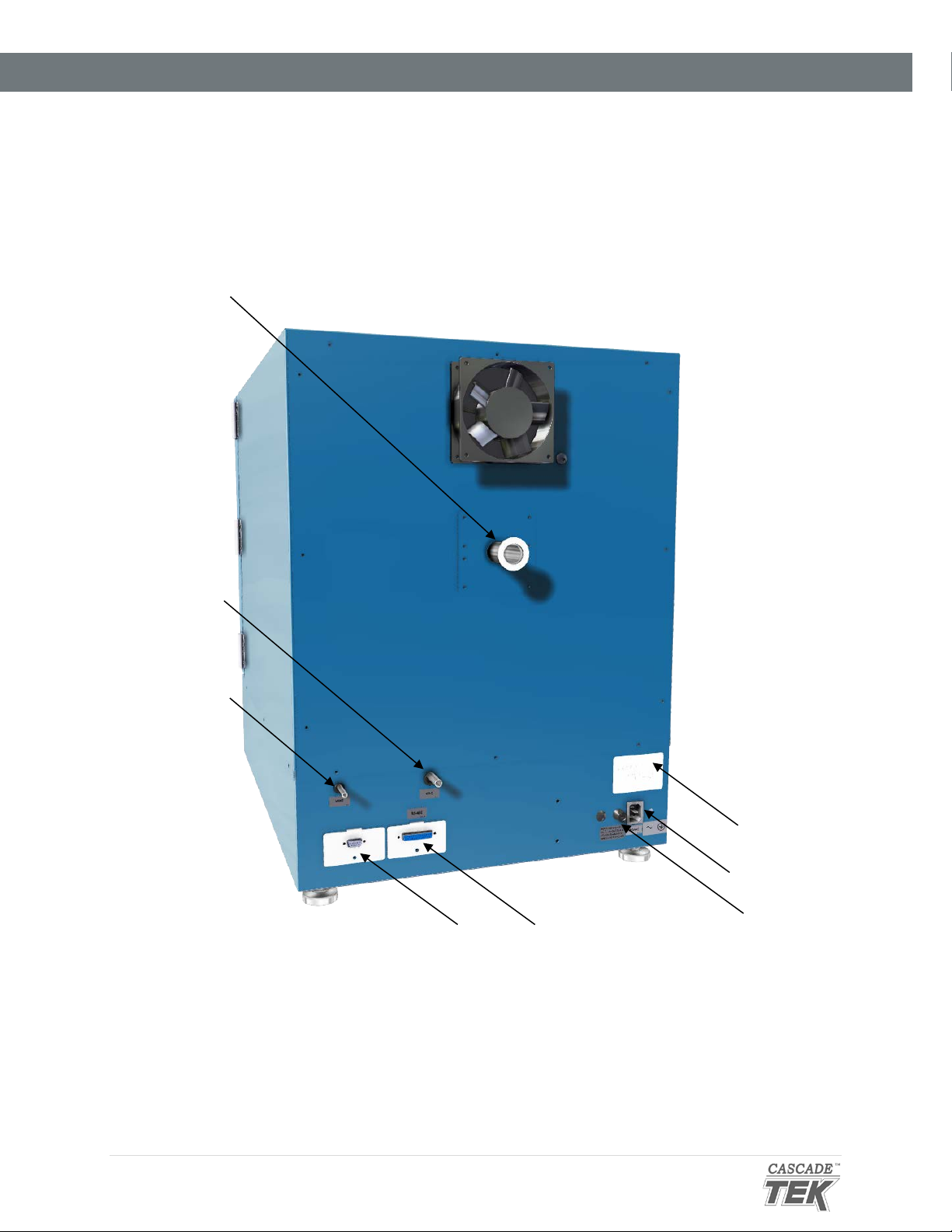
KF-25 Vacuum Port (Includes Blank and Clamp, not pictured here)
Vacuum Port, 3/8
Chamber Vent
RS485 Data Port - 25 Pin
Power Cord
Fuse Holder
9-Pin Voltage Output Port
Data Plate
RECEIVING YOUR OVEN
Back of Ovens
inch (9.52 mm)
Inlet Port ¼
inch (6.35 mm)
Inlet
14 | Page

RECEIVING YOUR OVEN
RECORD THE DATA PLATE INFORMATION
The data plate contains the unit model number, serial number, part number, and part ID. Tech
Support will need this information during any support call. Record it below for future reference.
• The data plate is located on the back of the oven above the power inlet.
MODEL NO:
SERIAL NO:
PART NO:
PART ID:
15 | Page

RECEIVING YOUR OVEN
16 | Page

INSTALLATION
INSTALLATION PROCEDURE CHECKLIST
For installing the oven in a new workspace location.
Pre-Installation
Verify that a vacuum supply source suitable for your application is available
and can be connected to the oven, page
• See page 23 for the oven gas and vacuum port locations.
Check that the required ambient conditions for the unit are met, page 18.
Check that the spacing clearance requirements are met, page 18.
9.
• Unit dimensions may be found on page 57.
Check that a suitable electrical outlet and power supply is present, page 19.
Install the oven in a suitable workspace location
Review the lifting and handling instructions, page 19.
Install the unit leveling feet, page 20.
Install the oven in its workspace location, page 20.
Set up the oven for use
Clean the oven shelving. Clean the chamber if needed, page 20.
Install the shelving in the oven chamber, page 21.
Connect the oven to its vacuum supply source along with any optional backfill gas
supply, page
23.
17 | Page

6” (152 mm)
KF-25 Port
6” (152 mm)
Door Swing
12” (305 mm)
12” (305 mm)
12” (305 mm)
6” (152 mm)
TVO-2: 20.5” (521 mm)
INSTALLATION
REQUIRED AMBIENT CONDITIONS
This oven is built for use indoors at room temperatures between 15°C and 40°C (59°F and 104°F), at no
greater than 80% Relative Humidity (at 25°C / 77°F). Operating outside these conditions may adversely
affect the oven temperature performance.
When selecting a location to install the unit, consider all environmental conditions that can adversely
impact its temperature performance. These include:
• Proximity to other ovens, autoclaves, and any device that produces significant radiant heat
• Heating and cooling vents or other sources of fast-moving air currents
• High-traffic areas
• Direct sunlight
REQUIRED CLEARANCES
These clearances are required to provide air flows for ventilation and cooling.
Fan
TVO-5: 27.0” (686 mm)
6 inches (152 mm) of clearance is required on the sides.
12 inches (305 mm) of headspace clearance is required between the top of the unit and any
overhead partitions.
Do not place objects on top of the oven.
A KF-25 vacuum port is located on the back of the oven for introducing vacuum-rated thermocouple
feedthroughs into the chamber or connecting to an external vacuum supply source. Leave sufficient
clearance for operators to safely access this port.
18 | Page

Standard 15-
INSTALLATION
POWER SOURCE REQUIREMENTS
When selecting a location for the unit, verify each of the following requirements is satisfied.
Power Source: The wall power outlet must meet the power requirements listed on the unit data
plate.
Model AC Voltage Amperage Frequency
TVO-2
TVO-5
• Wall power sources must be protective earth grounded and single phase.
• Wall power sources must conform to all national and local electrical codes.
• Supplied voltage must not vary more than 10% from the data plate rating. Damage to the unit
may result if the supplied voltage varies more than 10%.
• The recommended wall circuit breakers for these units are 15 amps.
110 – 120 10.0 50/60 Hz
110 – 120 13.0 50/60 Hz
amp NEMA
5-15 power
outlet.
• Use a separate circuit to prevent loss of product due to overloading or circuit failure. The circuit
must match or exceed the amperage requirement listed on the unit data plate.
Power Cord: The unit must be positioned so that all operators can quickly unplug the oven in the
event of an emergency.
• The unit comes provided with a 125 volt, 15 amp, 9ft 5 in (2.86m) NEMA 5-15P power cord.
Fuses: These units each ship with a 16 amp 250V 5x20mm fuse installed in a fuse holder
immediately adjacent to the power cord inlet.
• The fuse must be installed and intact for the unit to operate.
• Always find and fix the cause of a blown fuse prior to putting the unit back into operation.
LIFTING AND HANDLING
The oven is heavy. Use appropriate lifting devices that are sufficiently rated for these loads. Follow
these guidelines when lifting the oven:
• Lift the oven only from its bottom surface.
• Doors, handles, and knobs are not adequate for lifting or stabilization.
• Restrain the oven completely while lifting or transporting so it cannot tip.
• Remove all removable parts, such as shelves and trays, and lock doors in the closed position
during transfers to prevent shifting and damage.
19 | Page

INSTALLATION
LEVELING
The unit must be level and stable for safe operation.
Install the 4 leveling feet in the 4 corner holes in the bottom of the oven.
Note: To prevent damage when moving the unit, turn all 4 leveling feet so that the leg of each foot
sits inside the unit.
INSTALL THE OVEN
Install the unit in a workspace location that meets the criteria discussed in the previous entries of the
Installation section.
• Do not connect the oven to its power source at this time.
INSTALLATION CLEANING
The manufacturer recommends cleaning the shelving and oven chamber prior to installation of the
shelving in the chamber. The unit was cleaned at the factory but may have been exposed to
contaminants during shipping. Remove all wrappings and coverings from shelving prior to cleaning
and installation. Do not clean with deionized water.
See the Cleaning topic in the Operator Maintenance section (see page 43) for more information on
how to clean the oven chamber and shelving.
20 | Page

INSTALLATION
SHELVING INSTALLATION
Heating in a vacuum environment takes place primarily through conduction. Heat is transported from
oven elements inside the chamber walls or floor to the shelves. Install the shelves as described
below to ensure proper heat conduction and temperature measurement.
Never place samples or product on the oven chamber floor. The floor runs hotter than the shelf
temperatures. All oven heating specifications are for shelving temperatures only.
TVO-2
1. Carefully slide the short shelf into position on the chamber floor, sliding the clip on the bottom
of the shelf onto the oven temperature probe.
Temperature Probe Shelf Clip
Bottom of Short Shelf
• The oven probe extends from the back wall near the floor of the chamber.
• The short shelf must be on the bottom of the shelf-stack to ensure the oven
meets its temperature uniformity specifications.
2. Place the 2 tall shelves on top of the short shelf.
Continued on next page
21 | Page

Rocking Motion
Probe
Shelf
Install 4 Shelf Clips
Place the Shelf
INSTALLATION
Shelving Installation Continued
TVO-5 Shelving
To ensure accurate temperature measurement, one shelf bottom must be in close proximity to the
oven temperature probe. This probe extends out from the chamber back wall. Do not place the
shelf in direct contact with the probe.
1. Install the shelf clips in the slots of the shelf standard mounting rails located on the sides of
the chamber interior, 4 clips per shelf.
a. Squeeze each clip, insert the top tab first, and then the bottom tab using a
rocking motion.
2. Set the shelves on the clips.
a. Verify the shelves are level.
22 | Page

KF-25 Vacuum Port
Vacuum Line Connected
to the 3/8
Port
1. Vacuum Supply: Connect
Optional: Connect a clean
INSTALLATION
CONNECT TO THE VACUUM SUPPLY
Use clamps to secure tubing to the Vacuum and Vent Ports.
to the 3/8 inch (9.52mm)
Vacuum Port.
gas supply to the Vent
Port (Backfill Inlet). The
maximum allowed gas
pressure is 15 psi.
Vacuum and Gas Backfill Connections
Oven Chamber Ports – Left to Right
• Vent Port (Backfill Inlet) – 1/4 Inch (6.35 mm) OD
o External atmosphere backfills the oven chamber through this port when the Vent
Valve control on the front control panel is opened.
o A clean or inert gas supply source may be connected to this port. The maximum
allowed delivery pressure at the port is 15 psi.
• Vacuum Port – 3/8 Inch (9.52 mm) OD
o Chamber atmosphere is evacuated through this port. Connect the vacuum source to
the oven here.
o This port is opened and closed by the Vacuum Valve control on the front control
panel.
-inch Vacuum
• KF-25 Vacuum Port
o Comes with a clamp and blank.
o Used for introducing thermocouple probes through a vacuum rated feedthrough.
o A vacuum supply can be connected to the KF-25 port for increased efficiency in
vacuuming down the chamber. However, the Vacuum Valve control on the front
control panel will not affect the level of vacuum and must be set to closed to prevent
atmosphere from entering the chamber through the 3/8-inch Vacuum Port.
23 | Page

INSTALLATION
24 | Page

GRAPHIC SYMBOLS
The oven is provided with multiple graphic symbols on its interior and exterior surfaces. The symbols
identify hazards and the functions of the adjustable components, as well as important notes in the
operation manual.
Symbol Definition
Consult the operation manual
Consulter le manuel d'utilisation
Over Temperature Limit system
Thermostat température limite contrôle haute
AC Power
Repère le courant alternatif
I/ON O/OFF
I indique que l'interrupteur est en position marche.
O indique que le commutateur est en position d'arrêt.
Potential shock hazard
Risque de choc électrique
Recycle the unit. Do not dispose of in a landfill.
Recycler l'unité. Ne jetez pas dans une décharge
Protective earth ground
Terre électrique
Caution hot surface
Attention surface chaude
25 | Page

GRAPHIC SYMBOLS
26 | Page

Top Line (Red): Present chamber shelving
CONTROL OVERVIEW
Control Panels
Power Switch
The switch illuminates when in the ON ( I ) position.
Temperature Controller - Display on Homepage
temperature
Middle Line (Green): The constant
temperature setpoint
Bottom Line: Flashing “2” indicates active
heating
While on the homepage, the Up and Down arrow buttons adjust the constant temperature setpoint.
Pressing and holding both buttons navigates from the homepage to menu pages. On the menu
pages, the buttons adjust calibration offsets and heating profile variables.
When starting on the homepage, the green Advance button navigates forward through parameter
option pages including Event 1 (vacuum on or off) and units of measurement (Celsius or Fahrenheit).
The button also advances forward in menus and parameter lists when programming heating profiles.
The gray Reset button returns the display to the previous page or menu. Pushing the Reset button
repeatedly returns the display to the homepage.
The EZ1 button launches heating Profile 1. Pushing EZ1 again while running aborts Profile 1.
The EZ2 button launches heating Profile 2 (Step 11). Pushing EZ2 again while running aborts Profile 2.
27 | Page

Closed
Open
CONTROL OVERVIEW
Vacuum Gauge
As set at the factory, this gauge shows the chamber vacuum level relative to sea level
atmospheric pressure in inches of mercury (inHg). The display range is 0 to -29.9inHg. Zero
is the room atmosphere pressure at sea level and -29.9inHg a near-perfect vacuum. See
page 39 for how to display other units of measurement or zero the gauge to your local
altitude.
Vacuum Valve Control
This valve adjusts the level of vacuum draw applied to the oven chamber through
the vacuum port on the back of the oven.
• When open, this valve allows the connected vacuum supply to evacuate the oven
chamber.
• In the closed position, the valve cuts off the vacuum draw.
Vent Valve Control – Backfill Inlet
This valve controls the chamber inlet Vent Port on the back of the oven.
• In the open position, the oven chamber is open to external atmosphere through
the vent intake port on the back of the oven.
• Optional: An inert or clean backfilling gas supply connected to the Vent Port will
flow gas from the pressurized supply to the oven chamber when the Vent Valve is
open.
• When the valve control is in the closed position, the chamber is cut off from
external atmosphere and any gas supply.
o The vent must be closed before applying vacuum to the chamber.
Failure to do so may result in damage to your vacuum pump.
28 | Page

OPERATION
Safe operation of the oven is dependent on the actions and behavior of the oven operators.
Operating personnel must read and understand the Operating Precautions in this section prior to
operating the oven. The operators must follow these instructions to prevent injuries and to
safeguard their health, environment, and the materials being treated in the oven, as well as to
prevent damage to the oven. Failure to adhere to the Operating Precautions, deliberately or through
error, is a hazardous behavior on the part of the operator.
Le fonctionnement sûr du four dépend des actions et du comportement des opérateurs du four. Le
personnel d'exploitation doit lire et comprendre les consignes de sécurité et les précautions
d'utilisation de cette section avant d'utiliser le four. Les opérateurs doivent suivre ces instructions
pour prévenir les blessures et protéger leur santé, leur environnement et les matériaux traités dans
le four, ainsi que pour éviter d'endommager le four. Le non-respect des consignes de sécurité et des
précautions d'utilisation, délibérément ou par erreur, est un comportement dangereux de la part de
l'opérateur.
OPERATING PRECAUTIONS
• Do not use this oven in unsafe improper applications that produce flammable or combustible
gases, vapors, liquids, or fuel-air mixtures in quantities that can become potentially explosive.
• Outgassed byproducts may be hazardous to or noxious for operating personnel. Vacuum
pump exhaust should be vented to a location outside the workspace in a safe manner in
accordance with all applicable laws, ordinances, and regulations. Do not operate the oven in
an unsafe area with noxious fumes.
• Do not use this oven for applications heating hazardous fibers or dust. These items can
become airborne and come into contact with hot surfaces.
• Individual ovens are not rated to be explosion proof. Follow all building certification
requirements and laws for Class I, II, or III locations as defined by the US National Electric
Code.
• The bottom surface of the chamber should not be used as a work surface. It runs hotter than
the shelf temperatures. Never place samples or product on the oven chamber floor.
• Do not place sealed or filled containers in the oven. These may burst open when the
chamber is under vacuum.
• Do not place alcohol or mercury thermometers in the oven. With improper use, they can
rupture.
• Do not move the oven until it has finished cooling.
Warning Hot Surfaces: These areas are marked with Hot Surface labels. Proper protective equipment
should be employed to minimize the risk of burns.
Avertissement Surface Chaude: Ces zones sont marquées avec des étiquettes de surface chaude. Un
équipement de protection approprié devrait être utilisé pour minimiser le risque de brûlures.
29 | Page

OPERATION
THEORY OF OPERATION
Vacuum
Vacuum is supplied by an external vacuum supply (a pump or building system) connected to the
vacuum port on the back of the oven. Vacuum levels obtained in the oven chamber are dependent
on pump type and performance, valve settings, and the nature of the application or process,
including the volume of materials outgassed.
The chamber atmospheric pressure is displayed on the Vacuum Gauge on the main control panel.
The chamber should be sealed and evacuated at the start of a vacuum baking application. The oven
is not built to operate with the chamber exposed to atmosphere. Running the oven with the door or
the vent open risks destroying the vacuum pump, damaging the integrity of the oven chamber, and
may oxidize chamber surfaces.
Vacuum pumps and door gaskets should be selected on the basis of application type or process.
Pumps vary in suitability and safety depending on the outgassed byproduct types and moisture level
produced in the oven chamber. Gasket types are both resistant to and vulnerable to different
chemicals.
Gas Backfill
A gas supply can be connected to the vent port (backfill inlet) located on the back of the oven.
Nitrogen or another inert gas are typically used to avoid particulate contamination or the oxidation of
product that has not cooled down. The maximum allowed backfill pressure is 15 psi of delivery at the
port inlet. The port valve is opened and closed using the Vent control on the front panel.
Heating Options
The oven can either heat to and run at a constant temperature setpoint or execute a programmable
multistep heating profile with ramp up, heat soak, and ramp down intervals.
Heating in a Vacuum
In conventional ovens, powered elements transfer heat into the chamber air. The heated air then
circulates by natural convection or blower fan action, and surrounds the product on the shelves,
gradually bringing it to temperature. In a vacuum oven, heat transport takes place primarily by
conduction. The oven heating elements are located inside the chamber walls or floor, which in turn
transfer heat to the shelves. Each shelf then transports heat to the products or samples resting on it.
Direct radiant heating through infrared emission in a vacuum environment provides poor
temperature uniformity compared to conductive heating.
30 | Page

OPERATION
Heating Control
The oven temperature controller stores an operator-selected constant temperature setpoint. When
powered, the oven heats the chamber shelves to the setpoint. The controller board is wired to a
solid-state temperature probe located in the chamber on the rear wall. When the controller detects
that the shelf temperature has dropped below the temperature setpoint, it pulses power to the
heating elements.
The controller employs proportional-integral-derivative analytical feedback-loop functions when
measuring and controlling the shelving temperature. PID-controlled heating pulse intensities and
lengths are proportional to the difference between the measured shelf temperature and the current
setpoint. The frequency of pulses is derived from the rate of change in that difference. The integral
function slows the rate of pulses when the temperature nears the setpoint to avoid overshooting.
TVO ovens rely on natural heat radiation for cooling. The oven can achieve a low-end operating
temperature of the ambient room temperature plus the oven waste heat.
High Limit Control System
The temperature controller contains a heating cutoff system with independent circuitry connected to a
redundant solid-state temperature sensor probe inside the oven chamber. This high limit system depowers
the oven heating elements whenever the chamber shelving temperature exceeds the current limit setting.
This safeguards the oven in the event of a failure of the main temperature control circuitry or main
temperature sensor probe.
The high limit is set by the operator to a minimum of 10˚C above the highest temperature of the application
process the oven is currently being used for. Failure to set the high limit control system voids the oven
manufacturing defect warranty in the event of an overtemperature event.
31 | Page

3 Verify the Door and Valves are Closed
4 Turn on the Oven
VENT
OPERATION
PUT THE OVEN INTO OPERATION
Verify all of the required procedures in the Installation section have been carried out. Then perform
the following steps and procedures to prepare the oven for use in a new location.
Attach the Power Cord
1
2
Attach the power cord that came with the unit to the power inlet
receptacle on the back of the oven.
Plug the power cord into the workspace electrical supply.
5 Set the High Limit Temperature
Verify the oven chamber door is closed and latched, and
that the vent intake valve and vacuum valve are in the
closed position (turned all the way clockwise).
This safeguards your vacuum pump from exposure to
streaming atmosphere.
Place the oven Power Switch in the ON ( I ) position.
• The controller display will illuminate and default to its
homepage.
• The vacuum display will illuminate.
Set the Temperature High Limit to at least 10°C above the
highest intended temperature of your application, page 34.
6 Plug in the Vacuum Pump
32 | Page
Plug the vacuum pump power cord into a wall power source.
Continued next page

OPERATION
Continued from the previous page
Verify Vacuum Integrity
7
10 Minutes Minimum
Set the Operating Temperature
8
Place the Chamber Under Vacuum for a minimum of 10
minutes to verify the integrity of the vacuum supply system.
See page 35.
• Set the constant temperature setpoint. See
page 36.
Or
• Program multistep heating recipe profiles.
See page 36.
The oven is now ready for use
33 | Page
OPERATION
SET THE HIGH TEMPERATURE LIMIT
Note: Test the high limit system once per year for functionality.
The high temperature limit is set by the operator at least 10°C above the highest temperature the
oven will run at during your baking application.
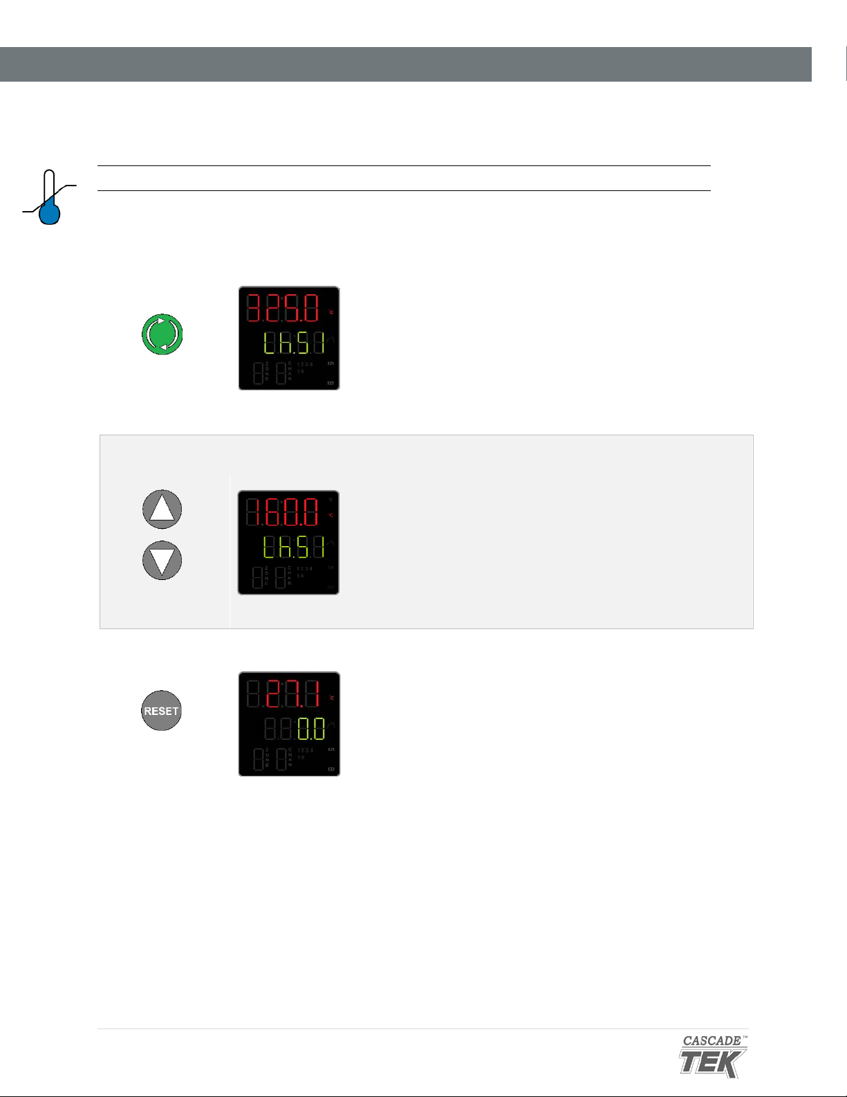
1. Advance to the Limit High Setpoint, starting on the homepage
Push Advance
Multiple Times
• Push the Advance button repeatedly until “Lh.S1”
(Limit High Setpoint) shows in the green midlevel display line.
2. Adjust the high limit to at least 10°C above the highest temperature of your application
Adjust
• The oven will automatically save and apply the
new High Limit setting after you have stopped
adjusting.
Note: If you are just checking the current high
temperature limit setting, push the Reset button to
exit the Limit High Setpoint menu and return to the
homepage without saving any changes.
3. Return to the homepage
Push Reset
•
Returned to homepage
End of Procedure
34 | Page

Evacuate the Oven Chamber
1. Verify the Vacuum and Vent Valve controls are in the closed position
3. Open the oven Vacuum Valve
Holding at Vacuum
Backfilling the Oven Chamber
4. Close the Vacuum Valve
• The pump may remain on.
VACUUM
VENT
VACUUM
OPERATION
EVACUATING AND BACKFILLING THE OVEN CHAMBER
Put the oven chamber under vacuum and hold for at least 10 minutes when first putting the oven into
operation in a new location to verify the integrity of the vacuum supply system. The oven chamber must
be drawn down to at least -3inHg (-76mmHg or -10kPa) in order to seal.
• This protects your vacuum pump from exposure to streaming
atmosphere.
2. Turn on your vacuum pump
Turn the Vacuum Valve control back to the closed position (clockwise) to
Turn the control all the way counter clockwise
• The Vacuum Gauge on the front panel should show
the chamber pressure decreasing.
• The achievable vacuum level is dependent on
altitude above sea level as well as the vacuum
supply efficiency and the volume of outgassed
byproducts. See page 40.
Continue evacuating the chamber throughout the baking application
to vent outgassed byproducts.
protect the vacuum pump from extended exposure to streaming
atmosphere.
5. Slowly open the Vent Valve
The chamber pressure gauge will count upward to zero.
End of procedure
35 | Page

2.
OPERATION
SETTING THE CONSTANT TEMPERATURE SETPOINT
1. Adjust the constant temperature setpoint on the homepage
Adjust
Release the arrow buttons after adjusting the setpoint
• There may be a brief pause as the oven controller
calculates the optimum power usage to achieve the
setpoint starting from the current oven chamber
temperature.
• A small illuminated 2 near the bottom of the display
indicates the temperature controller is calling for
heat.
Oven Heating
• Stay 10°C below the high limit
setpoint.
Note: Holding down an arrow
button will cause the
temperature to advance in
increments of ten (10).
HEATING PROFILES
Please see the profiles guide included with this oven for how to program automated heating recipes. The
guide provides illustrated explanations for all major profile functions and programming steps.
Pushing EZ1 launches heating Profile 1. Pushing EZ1 again while running aborts Profile 1.
Pushing EZ2 launches heating Profile 2 (Step 11). Pushing EZ2 again while running aborts Profile 2.
36 | Page

Alternating Alert Screens
OPERATION
HIGH TEMPERATURE LIMIT ACTIVATED
The High Limit system cuts off heating in the oven whenever the chamber temperature meets or
exceeds the Limit setting. Heating remains disabled until the oven operator clears the Limit cutoff.
Indicators
When heating is cut off, the oven display flashes two alternating alert screens.
Additionally, an illuminated “4” on the bottom display level specifies that the oven
should be routing electricity away from the heating elements.
Activation of the Limit cutoff is accompanied by a click sound.
Possible Causes of High Limit Activation
• The oven temperature is set above or near the High Limit cutoff setting. The
High Limit should be set at least 10°C above the highest intended
temperature of your heating application.
• A heat source in the oven chamber is pushing the oven temperature above
the limit setting.
• Significant outgassing in the chamber may be interfering with the measured
temperature.
• Attempting to heat a significant mass of product or samples may trigger a
temperature overshoot and subsequent Limit cutoff.
• The oven temperature controller circuitry or sensor probe have failed.
If you suspect an ignition event in the oven chamber or a hardware failure wait for the oven to
cool to room temperature before opening chamber door. Contact Technical Support for
assistance.
Clearing the High Limit Heating Cutoff
• Clearing the cutoff restores power to the oven heating elements.
Attention Screen
Heating Off
• The oven chamber temperature must be below the High Limit cutoff setting before
clearing the cutoff.
• Always verify it is safe to resume heating before clearing the High Limit cutoff.
1. Push the Reset button.
• The alert screens will flash 2 additional times before the oven controller clears the
cutoff, ending it.
37 | Page

x7
⁰C ⁰F
OPERATION
CHANGE UNIT OF MEASUREMENT
The controller can display temperatures in either Celsius or Fahrenheit.
1. From the homepage, advance to the “C_F1” unit of measurement
option.
a. Push the green Advance button 7 times.
2. Change the unit of measurement.
a. Use the Arrow button to change the parameter on the top
display line. “C” is Celsius and “F” is Fahrenheit.
3. After changing the Unit parameter, return to the homepage.
a. Push the Reset button.
38 | Page

Inches of Mercury
Kilopascals
Both
OPERATION
VACUUM GAUGE OPERATIONS
Change the Unit of Measurement
1. Place the vacuum gauge in its adjustment mode.
a. Press and hold the “M” button for approximately 3 seconds
• The display will begin to blink and show a unit of measurement
2. Use the arrow keys to scroll between units.
3. Exit the adjustment mode.
a. Press and hold the “M” button for approximately 3 seconds
• The display will cease blinking and show the current chamber
pressure.
Units of Measurement – Display Characters
kPa Kgf/cm2 bar psi mmHg inHg mmH2O
Zeroing the Gauge
As set at the factory, the vacuum gauge shows a reading of 0 inches of mercury (inHg) when the
chamber is at ambient (room) pressure. The display was set at near sea level.
If the gauge does not show 0 inHg when the chamber is at room atmospheric pressure, perform the
following steps.
1. With the chamber door open, press and hold both the Up and Down
arrow buttons.
2. Release the buttons when the display shows 0.0.
See page 58 for the zero equivalent for units of measurement other than inHg.
39 | Page

OPERATION
MAXIMUM OBTAINABLE VACUUM
The maximum obtainable vacuum is determined by the altitude of the oven workspace or laboratory
environment. The atmosphere is less dense at higher altitudes than at sea level. While a vacuum
pump will evacuate the same percentage of atmosphere from the oven chamber, less overall
pressure is expelled because of the reduced density.
Altitude
(Feet)
Sea Level Sea Level 14.70 psi -29.9 inHg
1000ft 305m 14.16 psi -28.9 inHg
2000ft 610m 13.66 psi -27.8 inHg
3000ft 914m 13.16 psi -26.8 inHg
4000ft 1219m 12.68 psi -25.8 inHg
5000ft 1524m 12.22 psi -24.9 inHg
6000ft 1829m 11.77 psi -24.0 inHg
7000ft 2134m 11.33 psi -23.1 inHg
8000ft 2438m 10.91 psi -22.2 inHg
9000ft 2743m 10.50 psi -21.4 inHg
10,000ft 3048m 10.10 psi -20.6 inHg
*In gauge pressure
Altitude
(Meters)
Atmospheric
Pressure
PRESSURE UNITS CONVERSION CHART
Maximum
Vacuum Level
Attainable
InHg kPa Kgf/cm2 bar psi mmHG mmH2O
1 inHg
1 kPa
1 Kgf/cm2
1 bar
1 psi
1 mmHG
1 mmH2O
40 | Page
1 3.3863 0.0345 0.3386 0.4911 25.400 345.32
0.2953 1 0.0102 0.01 0.1450 7.5006 101.97
28.9590 98.0665 1 0.9806 14.2233 735.55 10000.27
29.5300 100 1.0197 1 14.5037 750.06 10197.44
2.0360 6.8947 0.0703 0.0689 1 51.7150 703.09
0.0394 1.3332 0.0014 0.0013 0.0193 1 13.5954
0.0028 0.0098 0.0001 0.0001 0.0014 0.0029 1

OPERATION
DATA PORTS
25-Pin Port
The RS485 data port, located on the back of the oven, connects to the oven temperature controller.
The port is primarily intended for updating the controller software but can be used for data logging
and graphical profile programming. Accessing the controller with a computer requires a 25-pin
RS485-to-USB converter cable and driver software.
Applications and Utility Software
• National Instrument LabView and Watlow SpecView — Temperature monitoring and data
logging in graphical user interface environments.
• Watlow’s EZ Zone™ Configurator — Programming heating profiles in a drop-down menu
environment. Configurator can also be used to copy and save the controller configuration
file, which includes the currently programmed heating profiles.
o Configurator is available for free on the Watlow website.
9-Pin Port
This port connects with accessories ordered from the oven manufacturer, including data loggers.
41 | Page

OPERATION
42 | Page

OPERATOR MAINTENANCE
Warning: Disconnect the unit from its power supply prior to maintenance or cleaning of this unit.
Avertissement: Avant d'effectuer toute maintenance ou entretien de cet appareil, débrancher le cordon
secteur de la source d'alimentation.
CLEANING
If a hazardous material or substance has spilled in the unit, immediately initiate your site Hazardous
Material Spill Containment protocol. Contact your local Site Safety Officer and follow instructions per
the site policy and procedures.
• Do not use spray on cleaners or disinfectants. These can leak through openings and coat
electrical components.
• Do not use cleaners or disinfectants that contain solvents capable of harming paint coatings
or stainless steel surfaces. Do not use chlorine-based bleaches or abrasives, these will
damage the chamber liner.
• Consult with the manufacturer or their agent if you have any doubts about the compatibility
of decontamination or cleaning agents with the parts of the equipment or with material
contained in it.
Warning: Exercise caution if cleaning the unit with alcohol or flammable cleaners. Always allow the
unit to cool down to room temperature prior to cleaning and make sure all cleaning agents have
evaporated or otherwise been completely removed prior to putting the unit back into service.
Avertissement: Soyez prudent lorsque vous nettoyez l'appareil avec de l'alcool ou des produits de
nettoyage inflammables. Laissez toujours refroidir l'appareil à la température ambiante avant le
nettoyage et assurez-vous que tous les produits de nettoyage se sont évaporés ou ont été
complètement enlevés avant de remettre l'appareil en service.
Oven Chamber Cleaning Guidelines
1. Remove any removable chamber accessory items such as shelving if present.
2. Use 99% isopropyl alcohol to clean chamber surfaces and shelving. Apply using lint-free
wipes.
3. Take special care when cleaning around temperature sensor probes. Do not clean the probes.
4. Clean all removable accessories and components.
5. Verify the cleaning alcohol has evaporated completely from all chamber surfaces and
accessories prior to reconnecting the unit to its power source.
43 | Page

OPERATOR MAINTENANCE
MAINTAINING ATMOSPHERIC INTEGRITY
Periodically, inspect the door latch, trim, catch, and gasket for signs of deterioration. Failure to
maintain the integrity of the door system shortens the lifespan of the unit.
The gasket should be replaced if it is dry, cracked, or otherwise showing a loss of elasticity.
ELECTRICAL COMPONENTS
Electrical components do not require maintenance. If the oven fails to operate as specified, please
contact your distributor or Technical Support for assistance.
STORAGE
To prepare the unit for storage, remove all shelves, dry the chamber completely, and disconnect the
power supply. Be certain that the door is positively locked in the closed position.
44 | Page

1 2 3
4
OPERATOR MAINTENANCE
DIAGNOSTIC QUESTIONNAIRE — HEATING ISSUES
If the unit is experiencing heating issues, use this questionnaire to gather information on the unit prior to
contacting Technical Support. Gathering and sharing this information aids Tech Support in making timely
and accurate remote diagnosis. Additionally, data logger files as well as pictures and videos of the unit in
its failure mode are valuable diagnostic resources that can be shared with Tech Support.
Required: A copy of the unit Installation and Operation manual is required to carry out this procedure.
Overview
You will be performing the following tasks to gather onsite data:
Reading the Unit Performance
Specifications on page 46 and consulting
the operation manual for answers.
Recording your observations in the SDRAP Answers Log on page 49.
Observing the unit in operation using the
SDRAP diagnostic questions on page 48.
Sharing the gathered
information with Tech Support!
Unit Model Information
Find the unit data plate (see page 14) and the record the information on it below. This information is critical
for accurate diagnoses as displays, gauges, valves, and port types vary based on unit model and
customization options.
MODEL NO:
SERIAL NO:
PART NO:
PART ID:
45 | Page

OPERATOR MAINTENANCE
Note: Does the car actually have gas in the tank? Have you physically verified the computer is
plugged in? Yes, we are going ask some very basic questions. Please bear with us.
Methodical verifications and the elimination of potential causes of failure are often the
quickest means of getting a unit back into operation.
Unit Performance Specifications
Verify the following items to ensure a fault in the unit is preventing it from achieving its specified
performance levels.
Standard Ventilation Spacing Requirements
Verify there is sufficient spacing around the oven for ventilation or cooling. Insufficient spacing can
adversely impact temperature performance.
• A minimum of 6 inches (152 mm) clearance is required between the sides of the oven and any
walls or partitions.
• A minimum of 12 inches (305 mm) is required between the top of the oven and overhead cover.
• A minimum of 12 inches (305 mm) is required between the back of the oven and any partitions or
objects.
Operating Temperature Range of the Unit
Verify that your constant temperature setpoint or the setpoints of your heating profile all fall within
the operating range of the oven.
• See the Temperature Range specifications for the oven on page 58.
46 | Page

OPERATOR MAINTENANCE
Optional: Obtain a temperature reference device. A calibrated digital thermometer with a vacuumrated thermocouple feedthrough. The device must be accurate to at least 0.1°C.
Diagnostic Setup
1. The unit must be connected to a power source that meets the requirements in the Installation chapter
(page 19) and turned on.
2. Optional: secure the reference temperature device sensor probe at the center of the bottom shelf, with
the probe head in direct contact with the shelf surface.
3. The oven chamber must be sealed and be under vacuum. See the Place the Chamber Under Vacuum
entry on page 35.
4. The unit must have adequate time to come up to temperature and stabilize. Failure to wait will result
in an inaccurate diagnosis.
• Allow 120 minutes for the unit to achieve 150°C or 175 minutes to achieve 220°C. The
unit cannot come up to temperature and stabilize faster than these rates.
• Start the Diagnostic Data Procedure when the allotted time has passed, even if the
unit fails to achieve the setpoint temperature.
47 | Page

Chamber Temperature in Red
Setpoint
“2” indicates the
Alternating alert screens flash when the high limit heating cutoff is active.
OPERATOR MAINTENANCE
SDRAP Diagnostic Questions
Record the answers in the log on page 49.
Setpoint?
What is the current temperature setpoint?
in Green
Display?
What chamber temperature is presently showing on the temperature display?
Reference?
Optional: What temperature is the reference device presently showing for the chamber
temperature?
Ambient?
What is the room temperature? For best results, measure the temperature in the same section of
the room where the unit is located. Do not place your thermometer on the unit.
Pilot Lights?
1) Is the heating active indicator on the control panel flashing or otherwise illuminating, Y/N?
2) Is the High Limit cutoff active or has it activated recently, Y/N?
48 | Page
controller is calling for
power to the element

OPERATOR MAINTENANCE
SDRAP Answer Log
Record answers to the SDRAP questions in this log. These document the unit behavior.
SDRAP Record SDRAP Answers and Any Notes Here
Setpoint, present setting:
Display, present Temperature
reading:
Reference device, present
reading:
Ambient, present
temperature:
Heating Indicator:
Pilot Lights, illuminating Y/N?
High Limit Activated:
Other valuable diagnostic resources to share:
• Datalogger data
• Pictures and video of the unit in failure mode
• How long has the temperature issue been occurring?
Share!
Share the SDRAP and Unit Specifications data with Technical Support. This data is crucial for offsite
personnel making accurate remote diagnoses and is used to help ensure technical support can
resolve the issue.
Facilities Technicians
SDRAP and Unit Specifications data are also useful to any institutional repair technicians at your
facility who may be responsible for servicing of out-of-warranty units.
This page may be copied for institutional use
End Diagnostic Data Procedure
49 | Page

1 2 3
4
OPERATOR MAINTENANCE
DIAGNOSTIC QUESTIONNAIRE — VACUUM LEAK ISSUES
If the unit is experiencing heating issues, use this questionnaire to gather information on the unit prior to
contacting Technical Support. Gathering and sharing this information aids Tech Support in making timely
and accurate remote diagnosis. Additionally, data logger files as well as pictures and videos of the unit in
its failure mode are valuable diagnostic resources that can be shared with Tech Support.
Required: A copy of the unit Installation and Operation manual is required to carry out this procedure.
Overview
You will be performing the following tasks to gather onsite data:
Reading the Unit and Vacuum Performance
Specifications on page 51 and consulting the
operation manual for answers.
Recording your observations in the SDRAP Data Log on page 55.
Observing the unit in operation using the
SDRAP diagnostic questions on page 53.
Sharing the gathered
information with Tech Support!
Unit Model Information
Find the unit data plate (see page 14) and the record the information on it below. This information is critical
for accurate diagnoses as displays, gauges, valves, and port types vary based on unit model and
customization options.
MODEL NO:
SERIAL NO:
PART NO:
PART ID:
50 | Page

OPERATOR MAINTENANCE
Note: Does the car actually have gas in the tank? Have you physically verified the computer is
plugged in? Yes, we are going ask some very basic questions. Please bear with us.
Methodical verifications and the elimination of potential causes of failure are often the
quickest means of getting a unit back into operation.
Unit Performance Specifications
Verify the following items to ensure a fault in the unit is preventing it from achieving its specified
performance levels.
• Is the chamber being evacuated for the full duration of your baking application?
o Any outgassing from samples or products will raise the chamber pressure if the vacuum
valve is closed or the vacuum pump is turned off.
• The chamber must be evacuated to a minimum of -3 inHg (684 torr) to maintain a seal.
o The door will not seal completely at pressures higher than this.
o The vacuum pump must be rated to a minimum flow capacity of 1 cubic foot per minute (cfm)
per cubic foot of the chamber volume. Example: a 2 cubic-foot chamber should be
connected to a pump that can evacuate at least 2 cubic-feet per minute.
• Is the vacuum pump type suitable for your application or process?
o The vacuum pump must be resistant to byproducts outgassed during the baking process
with a sufficient evacuation rate to achieve your vacuum target.
• Is the gasket type suitable for the application?
o Each gasket type is resistant and vulnerable to different outgassed byproducts. A gasket
that is vulnerable to byproducts from your applications may fail after only a short period of
use.
o See page 60 of the operation manual to verify that the installed gasket is suitable for your
application.
Vacuum Specifications
Vacuum ovens cannot obtain perfect seals. The following specifications are the best performance
that can be expected of the oven in maintaining a vacuum environment.
• The baseline leak rate of the oven is less than 1 mTorr per 30 minutes at ambient temperature
when the oven chamber is empty.
• The lowest rated chamber pressure is less than 20 mTorr at 150°C.
51 | Page

OPERATOR MAINTENANCE
Diagnostic Setup
1. Check the primary chamber gasket for damage. This is the gasket mounted either on the chamber
liner or the door that seals the oven chamber when the door is closed.
Look for:
• Cuts or nicks on the gasket caused by removing shelves or samples
from the chamber.
• Cracking, brittleness, or loss of elasticity.
• Discoloration of the gasket.
• Nicks or other damage on the surface the gasket seals against.
2. The unit must be connected to a power source that meets the requirements in the Installation chapter
(page 19) and turned on.
3. Do not heat the oven. The oven must remain at ambient temperature for this procedure.
4. The oven chamber must be empty, sealed, and under full achievable vacuum levels. See the
Evacuating the Oven Chamber entry on page 35.
Vacuum Gauge
52 | Page

AND
OPERATOR MAINTENANCE
Diagnostic Questions
Pump On and Running?
Yes or no?
Vent Valve Closed?
The vent (backfill inlet port) must be closed before applying vacuum to the chamber. Failure to do so
may result in damage to your vacuum pump.
Vacuum Valve Open?
The vacuum valve must be open to allow a connected vacuum supply to evacuate the oven
chamber.
Vacuum Valve
Display Reading?
Record the chamber pressure level showing on the Vacuum Gauge display.
Reminder: Make sure to record the correct unit of measurement for the chamber pressure. See
the Vacuum Gauge Operations topic on page 39 to verify the current unit of measurement.
53 | Page

OPERATOR MAINTENANCE
Leak Verification, Y/N?
Verify that the oven is leaking and not experiencing outgassing from residual contamination.
1. If the oven is hot, allow it to cool to room temperature.
2. Evacuate the chamber to the lowest achievable pressure.
3. Write down the pressure displayed on the Vacuum Gauge as a positive number.
4. Isolate the chamber by closing the vacuum valve.
5. Monitor the vacuum gauge for 1 hour. If the pressure on the gauge increases, this may indicate a
significant leak.
6. Monitor the gauge for another hour.
• If the pressure level stabilizes, the initial rise in pressure may be caused by residual
material in the chamber outgassing, increasing the pressure.
• If the pressure level continues to increase, record the pressure displayed on the Vacuum
Gauge at the end of the second hour. Include these findings in the Diagnostic Data Log.
54 | Page
OPERATOR MAINTENANCE
Vacuum Leak Diagnostic Data Log
Record the diagnostic question answers in this log. These questions document the unit behavior.
Diagnostic Questions Record Answers and Any Notes Here
Pump On and Running, Y/N?
Vent Valve Closed, Y/N?
Vacuum Valve Open, Y/N?
Display Reading, Vacuum
Gauge:
Verified the Oven is Leaking,
Y/N?
Other valuable diagnostic resources:
• Datalogger files
• Pictures and video of the unit in failure mode
• How long has the vacuum issue been occurring?
Share!
Share the Vacuum Diagnostic Data Log and Unit Specifications data with Technical Support. This data is
crucial for offsite personnel making accurate remote diagnoses and is used to help ensure technical
support can resolve the issue.
Facilities Technicians
The Vacuum Diagnostic Data Log and Unit Specifications data are also useful to any institutional
repair technicians at your facility who may be responsible for servicing out-of-warranty units.
This page may be copied for institutional use
55 | Page

OPERATOR MAINTENANCE
56 | Page

UNIT SPECIFICATIONS
This oven is a 110 – 120 volt unit. Please refer to the oven data plate for individual electrical
specifications.
Technical data specified applies to units with standard equipment at an ambient temperature of 25°C
and at nominal voltage. The temperatures specified are determined in accordance to factory
standard following DIN 12880 respecting the recommended wall clearances of 10% of the height,
width, and depth of the inner chamber. All indications are average values, typical for units produced
in the series. We reserve the right to alter technical specifications at all times.
WEIGHT
Model Unit Weight
TVO-2 179.0 lb / 81.2 kg
TVO-5 360.0 lb / 163.3 kg
DIMENSIONS
Inches
Model Exterior W × D × H Interior W × D × H
TVO-2 20.5 x 29.5 x 26.3 12.0 x 20.0 x 12.0
TVO-5 26.5 x 34.5 x 32.3 18.0 x 24.0 x 18.0
Millimeters
Model Exterior W × D × H Interior W × D × H
TVO-2 521 x 750 x 667 304 x 508 x 304
TVO-5 673 x 876 x 819 457 x 610 x 457
CAPACITY
Model Cubic Feet Liters
TVO-2 1.67 47.2
TVO-5 4.50 127.4
SHELF CAPACITY BY WEIGHT
Model Per Shelf Maximum Total Load Max. No. Shelves
TVO-2
TVO-5 35.0 lb / 15.8 kg* 105.0 lb / 47.6 kg** 6 Shelves
*35.0 lb / 15.8 kg with weight evenly distributed across the shelf.
**105.0 lb / 47.6 kg total load
35.0 lb / 15.8 kg* 105.0 lb / 47.6 kg** 3 Shelves
in the chamber. Exceeding this limit risks damaging the chamber liner.
57 | Page

UNIT SPECIFICATIONS
VACUUM
All Ovens
Operational Vacuum Range
inHg mmHg kPa bar
-3.0 to -29.9 -76 to -760 -10 to -101
Vacuum Display Range
inHg mmHg kPa bar
0.0 to -29.9 37.5 to -757 5 to -101 0.05 to -1.013
Lowest Rated Chamber Pressure
24 mTorr at 150°C
-0.1016 to -1.0125
Leak Rate
Less than 1 mTorr per 30 minutes @ ambient temperature
TEMPERATURE
Range, Stability, and Uniformity
Model Range Stability Uniformity
TVO-2
TVO-5
Time to Temperature: From an ambient temperature of +20°C.
Model Heat Up to 80°C Heat Up to 150°C Heat Up to 220°C
TVO-2 70 Minutes
TVO-5 70 Minutes 120 Minutes
The maximum temperature is dependent on the type of door gasket installed. The oven comes with
a silicone gasket installed that is rated to 230°C. See page 60 for the temperature ranges of other
gasket types.
Ambient +20° to 220°C ± 0.2°C @ 150°C
Ambient +20° to 220°C ± 0.25°C @ 150°C
120 Minutes
±6% of Setpoint
±6% of Setpoint
175 Minutes
175 Minutes
POWER
Model AC Voltage Amperage Frequency
TVO-2
TVO-5 110 – 120 13.0 50/60 Hz
58 | Page
110 – 120 10.0 50/60 Hz

REPLACEMENT PARTS LIST
See the next page for gaskets
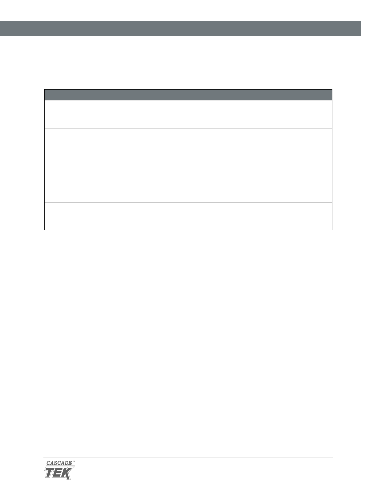
Description Parts Number Description Parts Number
Adjustable Leveling
Feet
Fuse, T16A 250V
5x20mm
Power Cord 125 volt,
15Amp, 9ft 5 in
(2.86m) NEMA 5-15P
Shelf Tall, TVO-2
2700506
3300513
1800510
5680567
Shelf Short, TVO-2
Shelf Clip, Individual (1),
TVO-5
Shelf, TVO-5
9751226
1250510
5680563
59 | Page

REPLACEMENT PARTS LIST
REPLACEMENT GASKETS
Available Gasket Types Part Number
Silicone, black or red, (comes with oven), rated to 230°C
Applications: General and high temperature
Resistant to: Moderate or oxidizing chemicals, ozone, and
concentrated sodium hydroxide
Attacked by: Many solvents, oils, concentrated acids, and
diluted sodium hydroxide
Buna-N rated to 105°C
Applications: Solvent
Resistant to: Many hydrocarbons, fats, oils, greases, and
hydraulic fluids.
Attacked by: Ozone (except PVC blends), ketones, esters,
aldehydes, chlorinated, and nitro hydrocarbons.
TVO-2: 3450707
TVO-5: 3450719
TVO-2: 3450708
TVO-5: 3450724
Fluorosilicone rated to 175°C
Applications: Acidic
Resistant to: Moderate or oxidizing chemicals, ozone,
aromatic chlorinated solvents, and bases.
Attacked by: Brake fluids, hydrazine, and ketones.
Viton® rated to 205°C
Applications: Acidic
Resistant to: All aliphatic, aromatic and halogenated
hydrocarbons, acids, and animal and vegetable oils.
Attacked by: Ketones, low molecular weight esters, and
compounds containing nitro.
Gasket Dimensions
TVO-2 – 12 x 12 Inches (305 x 304 mm)
TVO-5 – 18 x 18 Inches (457 x 457 mm)
Ordering Parts and Consumables
Parts may be ordered from Cascade TEK by calling 1-888-371-4096. Please have the model number and
serial number of the unit ready, as Tech Support will need this information to match your oven with its
correct part.
TVO-2: 3450611
TVO-5: 3450612
TVO-2: 3450670
TVO-5: 3450671
60 | Page

REPLACEMENT PARTS LIST
61 | Page

Cascade TEK Solutions LLC
P.O. Box 625 Bldg B
Cornelius, Oregon 97113
USA
support@cascadetek.com
cascadetek.com
1-888-835-9250
 Loading...