


This guide describes the visual inspection process for used Pyramid Probe cores. A Pyramid Probe core is considered
Quick Reference Guide
Pyramid Probes: Used Core Inspection
“Used” once it has touched down on a wafer. Visual inspection should be performed first visually, and then with a
microscope. The recommended procedure employs two microscopes:
This guide describes the visual inspection process for new Pyramid Probe cores. Inspection should be performed first
visually, and then with a microscope. The recommended procedure employs two microscopes:
Low-magnification microscope
(with a large working space)
• Commonly used for PCB inspection and
soldering stations
• Used for inspecting the entire probe, core
window, components and membrane wing
• Magnification range should be approximately
7x to 90x
High-magnification microscopes
• Used for inspecting the probe face, probe tips
and beams
• Recommended microscope objectives include
5x, 20x, and 50x
When saving photos, be sure to include the serial number in the file name.
Use the Pyramid Probes Certificate of Conformance to verify the following:
• The serial number on the core frame matches the Pyramid Probes Certificate of Conformance.
• The product name on the Pyramid Probes Certificate of Conformance matches the product to be tested.
Step 1: Edge Sense Inspection
Pyramid Probes used on manual probe stations have an edge sense type mechanical switch installed. This step applies
only to manual probe stations.
Pyramid Probes used on manual probe stations have an edge sense-type mechanical switch installed. The edge sense
needle contacts a glass pad on the spring in some Pyramid Probes. When installed on larger frame cores, the edge sense
needle contacts the core spring directly. This step applies only to manual probe stations.
Inspection Area Criteria
Edge Sense
(if glass pad is
installed)
Are there cracks in the glass pad?
Contact local support for instructions.
Is the glass pad securely in place?
Contact local support for instructions.
Is the needle touching the glass pad, and roughly centered?
Contact local support for instructions.
PN 153-691-2 www.cascademicrotech.comI Pyramid Probes: Used Core Inspection• 1

Step 2: Low Magnification Microscope Inspection
Tes t er S i d e
Wafer Side
Pyramid Probes: Used Core Inspection
Inspection Area Criteria
Membrane
Plungers
Are there any tears noted anywhere on the membrane?
A membrane tear is defined as a torn membrane caused by mishandling or equipment malfunction. Tears on a
new core that have been repaired by the factory are acceptable, as long as the repaired patch does not exceed
1000μm.
Tears resulting in signal damage to a critical trace cannot be repaired.
Cores with tears that do not include critical traces should be returned for repair to prevent propagation.
A torn trace can be waived by Engineering if it is not critical to the test program.
Has the membrane come off the alignment pin?
WARNING: Do not install in a box or board until repaired.
Contact local support for instructions.
Is there any damage to the membrane?
Escalate to a higher magnification inspection to determine if there is a failure.
Is the probe face clean of any debris?
Follow the procedure in Pyramid Probe Core Off-line Cleaning With Brush to clean the face after incoming
inspection is complete.
Are there any cracks noted in the plunger beams from the tester side?
If cracks are noted, contact local support for instructions.
Are there any cracks in the plunger beams from the wafer side?
Skip this step if the core is installed in a PCB.
If cracks are noted, contact local support for instructions.
PN 153-691-2 www.cascademicrotech.comI Pyramid Probes: Used Core Inspection• 2
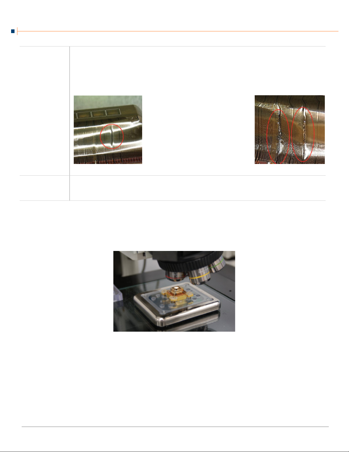
Components
Low-magnification photo of wing
on VLSR core. Burnt trace
verifies test failure for open. It has
been damaged by high current.
Low-magnification photo of wing.
These two traces would fail
electrical test as open circuits. They
were damaged by high current.
Pyramid Probes: Used Core Inspection
Is there any damage to installed components?
Small scratches from the assembly process are acceptable.
Cracked solder joints, cold solder joints or lifted component pads are unacceptable at any time in the core’s life
Damaged components can be waived by Engineering if the electrical signal is not affected.
Note any damage that indicates incorrect handling during installation of the core and provide feedback to
engineeering.
Traces
Is there any high current damage to traces?
The pass/fail criteria is the test program.
Provide feedback to Engineering to check program for current protection on this signal.
Step 3: High Magnification Microscope Inspection
Inspect Core Using the 5x Objective
1. Place the core on a high-magnification fixture with the probe tips up.
PN 153-691-2 www.cascademicrotech.comI Pyramid Probes: Used Core Inspection• 3

2. Inspect the core using the 5x objective.
Adhesion loss appears near the corner of the membrane.
This is acceptable because there is no large bulge.
Pyramid Probes: Used Core Inspection
Inspection Area Criteria
Probe Face
Membrane
Are there any scratches on the probe face?
Note any scratches on the probe face.
Are any particle hits visible on the membrane?
An indentation in the membrane surface is not a failure. Use the criteria for damage to traces to determine
pass/fail.
Are there any particles embedded in the membrane?
The following criteria describe unacceptable embedded particles:
• Large or deeply embedded particles that cause shorts between traces or layers
• Large embedded particles that cause open traces
• Tall, embedded particles that contact the wafer (maximum particle height is difficult to define; there are
many variables, such as probe tip height, overtravel, membrane design, surface flatness, etc.)
Is there any repeatable diagonal indentation in the membrane?
This is caused by a particle on the cleaning
media.
Follow the pattern of indentations to verify
that a probe tip is not damaged.
Use the pass/fail criteria for scratches to
evaluate the indentations.
Are there any tears in the membrane at the corners of the probe face?
Tears on the probe face cannot be repaired.
Are there any tears along the edges of the wings?
• Fail if a signal is damaged electrically.
• Return for repair to prevent propagation of tears that do not include a signal trace.
Is there any adhesion loss noted on the probe face between the membrane and plunger
stack?
Adhesion loss causing the membrane to
bulge is unacceptable. Focus on the
membrane surface to verify the bulge is not
taller than the probe tips.
PN 153-691-2 www.cascademicrotech.comI Pyramid Probes: Used Core Inspection• 4

3. Inspect the core using the 20x objective.
Anomaly examples
Cracks originating from beam Cracks parallel to trace
Pyramid Probes: Used Core Inspection
Inspection Area Criteria
Tips
Do all tips appear uniform in size and shape?
On a used core, missing, tilted or crushed tips can be waived by Engineering if they are a redundant contact
like ground or power, or if they still have electrical continuity.
Is there any high current damage to the signal trace evident around the probe tip?
The pass/fail criteria is the test program.
Provide feedback to Engineering to check
program for current protection on this
signal.
Electrical Traces
Surface Layer
Cracks
Are any anomalies present that affect the electrical trace metal?
An anomaly is something different,
abnormal, peculiar or not easily classified.
Anomalies greater than 50% of an electrical
trace width are acceptable on used cores if
the core passes electrical test.
Anomalies affecting the ground grid are
acceptable.
Are there any cracks in the electrical traces?
Cracks greater than 50% are acceptable on used cores if the core passes electrical test.
Cracks affecting the ground grid are acceptable.
To troubleshoot an electrical open, inspect the trace:
• First, inspect the immediate areas of component connections.
• Inspect the probe tip.
• Inspect the entire length of the trace.
Cracks may be present in the surface layer of the polyimide.
• Cracks originating from the beam are
acceptable
• Cracks parallel to an electrical trace,
but not within 20 µm of the beam are
acceptable.
PN 153-691-2 www.cascademicrotech.comI Pyramid Probes: Used Core Inspection• 5

Middle Layer
Acceptable
Not acceptable. Membrane is
cracked and has some separation.
Acceptable
Cross section with internal
encapsulated particle
Acceptable
Pyramid Probes: Used Core Inspection
Polyimide
Are there any cracks in the Middle Layer Polyimide that do not come to the surface?
This type of crack is acceptable unless it is
causing other damage to the membrane,
such as separation between the layers or
cracks through the entire membrane.
Stress Cracks
Membrane
Surface
Are there any cracks in the surface layer of the membrane where it bends at the edge of the
face?
These cracks are not in the metal. They
are in the polyimide.
Change the focus of the microscope to
confirm the cracks are in the polyimide.
If cracks also appear in the electrical
traces, refer to the appropriate criteria in
Electrical Traces on page 5.
Were any particles created or formed below the membrane (poly2) surface during the
thinfilm fabrication process?
Internal encapsulated particles are acceptable as long as they pass all other specifications.
Polyimide may appear rough and discolored around the beams, component attachment pads, or any other
plated metal area forming part of the membrane surface:
• On the probe face, this is acceptable up to 200µm radius around the beams or other plated metal area
forming part of the membrane surface.
• On the wings and the interface area, this is acceptable in all areas.
PN 153-691-2 www.cascademicrotech.comI Pyramid Probes: Used Core Inspection• 6

Beams
Pyramid Probes: Used Core Inspection
Are there any cracked beams?
Cracked beams can be waived by Engineering if they are a
redundant contact such as ground or power, or if they still have
electrical continuity.
Is beam slope greater than 10μm?
The probe tip is near the end of its life. Contact Engineering.
See the Pyramid Probe Core User Guide for more details on measuring beam slope.
Is there beam slope throughout all beams?
Beam slope throughout may indicate one of the following:
• Too much overtravel
•End of life
Is the beam slope isolated?
Isolated beam slope can indicate one of the following:
• Particle hit
• Mishandling
• Stepping off wafer
4. Inspect the core using the 50x objective. The primary goal at this magnification is to inspect the surface of the probe tip.
Inspection Area Criteria
Probe Tips
Is there any organic buildup or fibers on tips?
Fibers are not acceptable on used probe tips.
Used cores will have small amounts of organic contamination from probing or cleaning that might not be
completely removed by off-line cleaning.
To remove contamination, see the procedure in Pyramid Probe Cores Off-line Cleaning With Brush.
Is there any metal present on the probe tips?
Metallic buildup on the tips is acceptable if the core passes electrical test.
If there is aluminum or solder contamination covering more than 25% of the probe tip surface, provide
feedback to Engineering to evaluate the online cleaning parameters and the cleaning film.
Are the probe tips textured?
Probe tips for gold pads do not need texture, but can have a textured tip surface.
Probe tips for probing all other metals, must have texture on 25% of the tip surface.
Do the probe tips meet height and diameter dimensions?
For used cores, the criteria for tip height is to pass functional test.
For used cores, the criteria for tip diameter is device-specific to the passivation opening.
Do adjacent probe tips have a height difference greater than 2μm?
A height difference greater than 2μm on a used core is acceptable if electrical contact is made at production
overtravel.
PN 153-691-2 www.cascademicrotech.comI Pyramid Probes: Used Core Inspection• 7
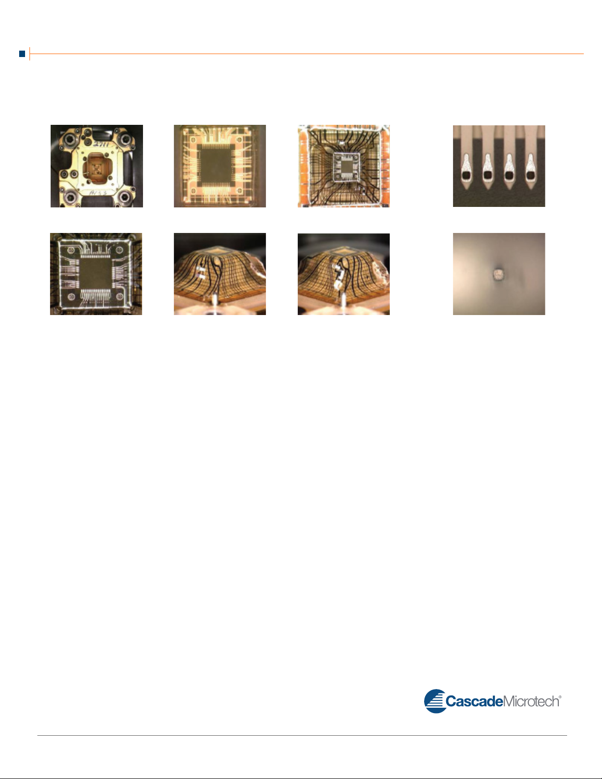
Example Images
© Copyright 2011 Cascade Microtech, Inc.
All rights reserved. Cascade Microtech is
a registered trademark of Cascade Microtech, Inc. All other trademarks are the
property of their respective owners.
Data subject to change without notice.
Pyramid Probes: Used Core Inspection
Entire Probe Core Window Entire Membrane Beams @ 50x
Probe Face Wing North and East Wing South and West Probe Tips@ 50x
Low Magnification Scope High Magnification Scope
Cascade Microtech, Inc.
Corporate Headquar
toll free: +1-800-550-3279
phone: +1-503-601-1000
email: cmi_sales@cmicro.com
ters
PN 153-691-2 www.cascademicrotech.comI Pyramid Probes: Used Core Inspection• 8
Germany
phone: +49-89-9090195-0
email: cmg_sales@ cmicro.com
Japan
phone: +81- 3-5615-5150
email: cmj_sales@ cmicro.com
China
phone: +86-21-3330-3188
email: cmc_sales@ cmicro.com
eSingapor
phone:
+65-6873-7482
email: cms_sales@ cmicro.com
Tai wa n
phone: +886-3-5722810
email: cmt_sales@cmicro.com
 Loading...