


www.casals.com
CV072018-1
CTRL-MAX
2
USER MANUAL AND SETUP INSTRUCTIONS

2
CV072018-1
INDEX
MAIN WINDOW DISPLAY
MANAGEMENT OF FAN SPEED, FLOW OR CONSTANT PRESSURE
BOOSTER FUNCTION
AIR POST-TREATMENT MANAGEMENT
PREHEATING MANAGEMENT
SELECTION MENÚ
STATUS MENÚ: OPERATING STATUS
PROGRAM MENÚ: MANAGEMENT OF THE WEEKLY SCHEDULE
DEFAULT/ PROG. PREDEF.
TIMETABLE
ADJUSTMENT OF SPEED LEVELS
CLOCK MENÚ: CLOCK SETTINGS
ALARMS MENÚ VISUALIZATION OF THE STATUS OF THE ALARMS
INSTALLER MENÚ: CONFIGURATION OF THE INSTALLATION PARAMETERS
WINTER/ SUMMER TEMPERATURE
MODBUS COMMUNICATION
BOARDS
INSTALLATION
WIRING CONTROL PANEL
CONTROL CHARACTERISTICS
WARRANTY CONDITIONS
DIMENSIONS
MOUNTING
p. 3
p. 4
p. 5
p. 5
p. 6
p. 6
p. 7
p. 9
p. 10
p. 11
p. 12
p. 13
p. 13
p. 16
p. 17
p. 24
p. 26
p. 27
p. 31
p. 31
p. 31
p. 31
p. 32
p. 33
3
CV072018-1
VISUALIZATION MAIN SCREEN
The touch screen control panel has been designed to manage units of Mechanically Controlled Ventilation with Heat Recovery (VMC-RC) in
a simple and intuitive way. The user manages the control by means of the icons of the graphic screen making a slight pressure on them; The
direction buttons, which appear after the pressure in a modifiable parameter, allow the user to interact with the unit by going through menu
items and modifying values. Pressing the OK button confirms the modifications or selections made. The color change (green) of an icon after
a press indicates that the parameter represented by that icon can be changed. When an element of the submenus is highlighted, it appears in
background color on a blue background, pressing OK the title changes to green and modifications can be made with the direction buttons.
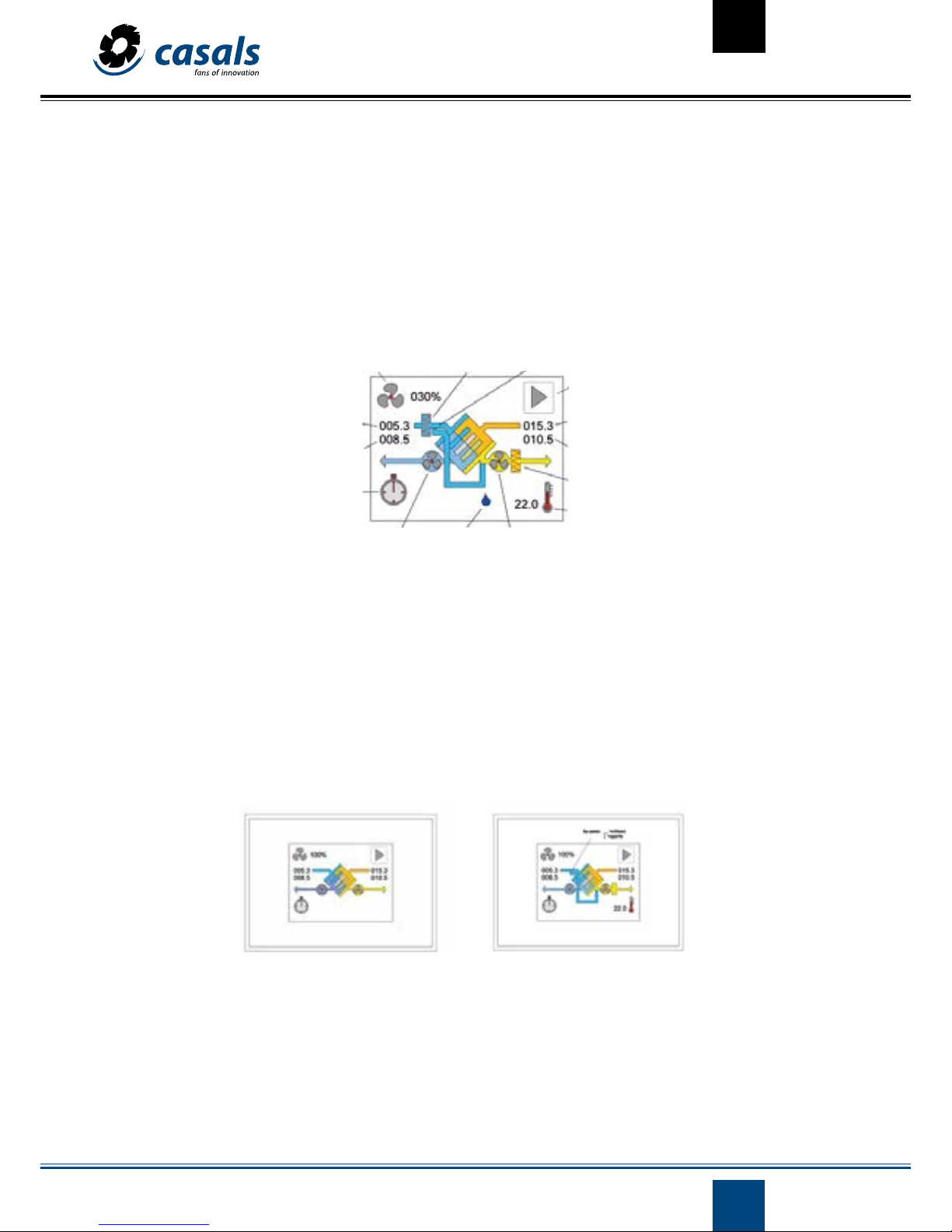
The main window is a detailed graphic representation of the state of the machine from which all available functions can be activated. To change the window and access the other menus, you have to press the icon to change the menu window. From the other windows you can return
to the previous one by selecting the mentioned icon and pressing OK. To save energy the control is placed in standby mode (paid screen) after
a minute of inactivity, pressing at any point on the screen is automatically reactivated. In the presence of alarms, on the other hand, the screen
lights up for half a second approximately every ten.
Unit without bypass Unit with bypass
*= Modifiable parameter
Exhaust fan
External air temperature
* Fan speed sign Preheating sign (CTRL-MAX
2
)
* Change screen sign
Temperature return air
Temperature air in
Post-heating sign
* Adjustment point temperature
By-pass sign
Expelled air temperature
* Timer
Humidity sign Supply fan
4
CV072018-1
MANAGEMENT OF FAN SPEED, FLOW OR CONSTANT PRESSURE
To modify this parameter, the icon at the top right of the synoptic table must be selected by clicking on it (it will turn green and the direction
buttons will appear). Then press the icon of the address button up to increase or down direction to decrease the value located next to it; Once
the desired one is located, press the OK button to confirm the selection. At first it is possible to turn off the machine directly by pressing the
central button, it disappears automatically by pressing the direction buttons. The variation can be expressed as a percentage for variable speed machines, with a simple 1-2-3 for machines with 3 speeds, in flow (m³ \ h) for machines with constant flow or pressure (Pa) for machines with
constant expression (equipped with the corresponding supplementary kit, see page 29). For these last two models, once the desired value has
been selected, the speed of the fans will automatically vary to keep the flow or the set pressure constant. For machines with a sensor mounted
different from the cop / cav kit, but always with constant pressure or flow rate, enter the percentage value of the pressure or flow scale of the
unit. The regulation it will be carried out in the same way. This also applies to the settings of the weekly programming menu (Program). In
addition to the scale value, the timer element will appear and, if selected, will start the default weekly time program (see Program menu). If an
air quality, relative humidity sensor is present in the unit or if the analog input (0-10V) is activated, we will also have the automatic selection
that allows the automatic regulation of the fan speed in function of CO2, Humidity measured or by an external signal.
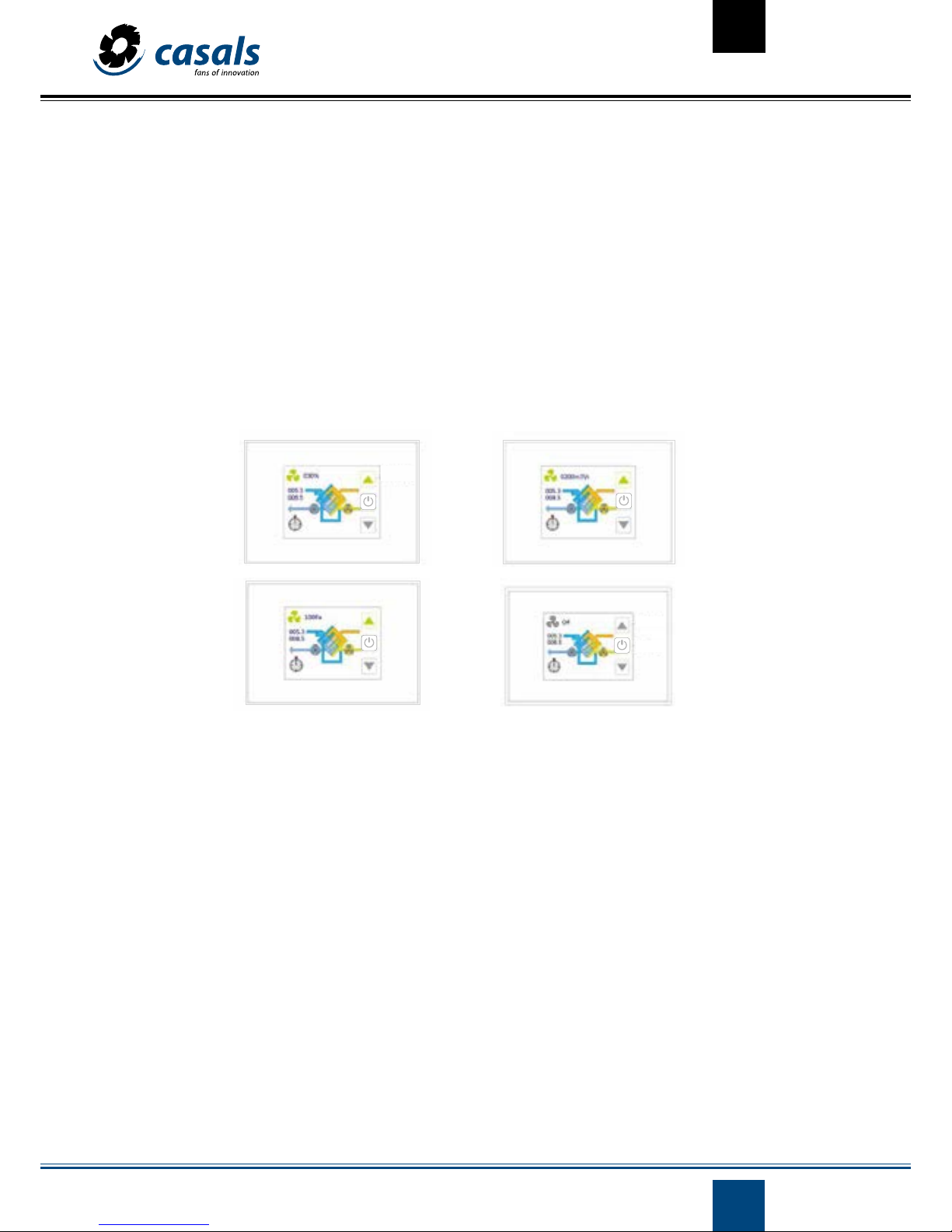
In detail the possible selections are:
- off: with this selection, the fans are stopped. Be careful because in any case the unit is electrically powered; this value is obtained by descending below the minimum adjustable speed.
-xxx%: if the unit has modulating fans it is possible to adjust a percentage value of the speed, flow rate or full-scale pressure (for units not
equipped with the corresponding kit but always in a cop / cav version with a different sensor), starting from a minimum (factory adjusted) to
100% with steps of 5% (1% on request).
-1, 2 or 3: if the unit is equipped with 3-speed fans, it is possible to select one of the available ones: speed 1, speed 2 or speed 3.
-watch: with this selection the speed of the fans is controlled according to what is established by the weekly chronoprogram (see Program
menu), this indication is obtained by selecting a value higher than the maximum speed (100% or 3).
- auto: this mode is available only if a sensor (CO2, CO2-COV, relative humidity HR) or an external signal (0-10V) is present. It is obtained by
selecting a value higher than clock.
- xxx m³ \ h: if the unit is a constant flow (CAV) version with a kit, the desired value can be set in m3 \ h of flow. The fans will be regulated automatically to keep it constant depending on the changes in the load.
Speed fan controller (%)
Airflow control
Pressure control
Direction buttons
Direction buttons
on/off
5
CV072018-1
BOOSTER FUNCTION
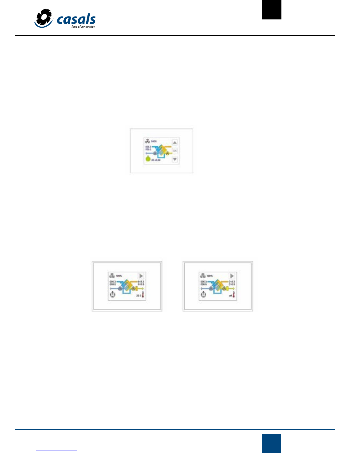
By selecting the icon on the lower left you access the booster function. Through this you can select a time interval (from a minimum of 1 minute to a maximum of 4 hours) in which to operate the unit at maximum power. The booster function is a priority with respect to other modes
of fan speed management.
After the selection a digital chronometer (hours.minutos.seconds) predetermined to a value of 10 minutes can be modified with the direction
buttons on the right of the screen: up to increase the booster time and down to decrease this time. Pressing the OK button starts the function:
the remaining time for the end of the process is shown on the screen.
When the value 00.00.00 is reached, the fans are controlled again in the previous way. If it is desired to stop the process, it is sufficient to repeat
the adjustment operations of the booster by selecting a time of 0 minutes and pressing OK.
MANAGEMENT OF AIR POSTGRADING
The control is capable of managing an air after-treatment system with both water coil and electrical resistance.
The first is regulated by the control of a 3-point solenoid valve 230V or 24AC-DC \ 0-10V, while the resistance through the corresponding relay.
If after-treatment management is established, the main screen is modified: an icon - thermometer with a temperature value appears in the
lower right corner. On its side and on the flow of the driving air, a picture of post-heating / cooling appears.
Selecting the icon in the bottom right corner establishes the desired temperature set point (TS) inside: the user can increase the value of TS
with the direction arrow up or, on the contrary, decrease it with the Direction arrow below. Once the desired value has been reached, the selection is confirmed by pressing the OK button. With the central button, which appears at first, the post-treatment can be switched off directly.
TS can assume values between 05.0 ° C and 30.0 ° C with steps of 0.1 ° C; if the user selects a TS value lower than 05.0 ° C, the control considers
the post-heating deactivated and the display appears next to the corresponding icon on the screen. It is possible to combine electric afterheating for winter and water cooling in summer, or under the same conditions, control two separate cold-hot coil (cold only with 0-10V valve).
TS becomes the reference for heating or cooling depending on whether or not these are enabled in the corresponding station of the installer
menu (exclusive to each other) and depending on the one selected in the parameter menu. The post-heating status is shown in the main
window: It is also possible to manage a dehumidification system made by the two separate coil (hot-cold) or by a cold coils with an electrical
resistance underneath.
Active post-heating
Postheating off
6
CV072018-1
PREHEATING MANAGEMENT
In addition to the post-heating, the CTRL-MAX2 control is able to manage an electric preheating system (operated by a PWM signal or on-off)
to prevent the formation of ice inside the heat exchanger. The control automatically activates the anti-frost procedure when the temperature
measured by the expulsion probe (Tx) drops below the value of 3 °C. Here the heater is powered at the minimum power. If the temperature Tx
continues to decrease and falls below 1 °C, the feed of the preheater is progressively increased until it reaches 100%. When Tx returns above
3 °C the procedure is interrupted. The temperature values 3C° and 1C° are set at the factory and can be modified on request. The preheating
status is shown in the main window.
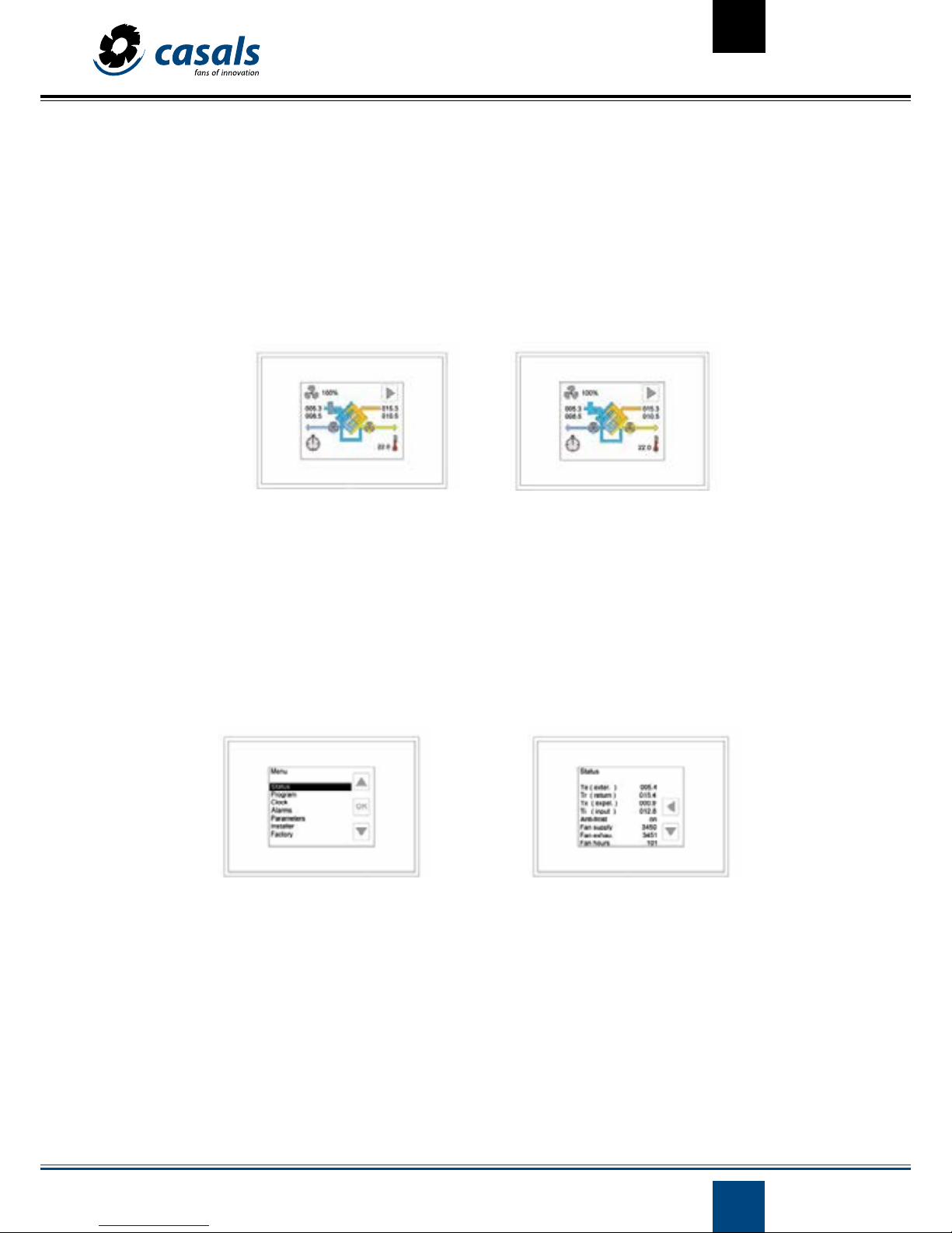
MENU SELECTION
From the main window you access the menu window by touching the corresponding icon (window change icon). You have to scroll with the
up arrow key and then press OK on the desired item. When selecting, you access the diverse detailed information about the installation. When
the last menu item is reached, the arrow below disappears.
On the other hand, when you go beyond the first one, the window change icon appears with the arrow to the left. To return to the previous
menu, click on the latter.
In the menu window you can access the following functions:
- Status
- Program
- Clock
- Alarms
- Installer
- Factory (protected by password, accessible only by factory).
From the Menu window, you access the main window by pressing the up arrow button until the window change icon appears and pressing OK.
Menu selection window
Active post-heating
Postheating off
Central window change icon
7
CV072018-1
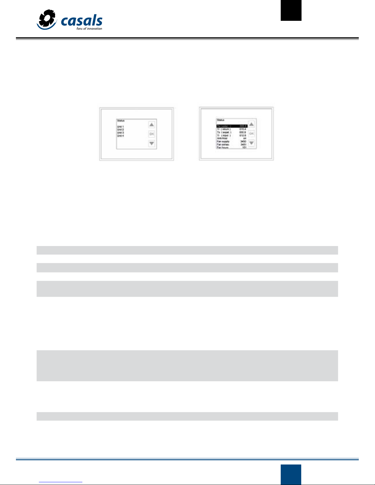
STATUS MENU: OPERATING STATUS
If the remote control panel is used to manage several units (master-slave mode), a screen with the list of available machines (max 4) will appear
in the menu:
To view the status of an individual unit, select it (move with the arrows and confirm the selection with OK). If the control is configured to manage an individual unit, when accessing this menu, the status of the unit is displayed directly, displaying the values taken by the parameters
that characterize it; using the direction buttons (up-down) it is possible to scroll through all of them. The pressure, flow parameters refer to
machines with cop / cav kit (see instructions):
Te (exter.) Renewal air temperature in °C
Tr (return) Return air temperature in °C
Tx
(expelled)
Expelled air temperature in °C
Ti (input) Air temperature introduced in °C
Tw(water) It is active if the after-heating is present by means of a water coil, it indicates the temperature of the water flowing
out of the coil, it is expressed in ° C
Wat.nofrost It is active when the after-heating is established by a water coil and indicates whether the anti-freeze / no-frost
mode is in progress.
The no-frost function relative to the coil is activated when the temperature measured by the Tw probe falls below
3 ° C and then deactivates when it returns above 5 ° C (3 + 2). When a temperature below 3 ° is detected, the control
valve (hot water) is completely opened in order to prevent the formation of ice inside the elements. If Tw falls below
1C ° the fans stop and at the same time an alarm is signaled (see ALARMS menu). The two temperature values of 3
° C and 1 ° C can be changed (menu FACTORY -factory-).
Anti-frost Antifrost function (antifreeze) exchanger. It is activated when the temperature measured by the Tx probe falls be-
low 1 ° C and then deactivated when it returns above 3 ° C.
The purpose is to avoid the formation of ice inside the exchanger.
It can be managed by a preheating resistor, by unbalancing the air flow rates or by regulating the by-pass.
Fan supply Admission fan speed, this value is expressed in:
- Revolutions per minute (RPM) if fans with tachometer signal are installed.
- Percentage if variable speed fans are installed without tachometer signal (Off with fan off).
- Off, 1, 2 or 3 for three-speed fans.
Fans. remote Only Evo-d. If on, it indicates the independent regulation of the drive fan from Modbus.
Flow supply Only for units of constant flow with control over two flows. Value in m³ \ h of flow of the driving fan.
Display menu statusSelection of unit to control configuration menu status
8
CV072018-1
Dp Supply Only for units of constant pressure with control over two flows. Pressure value in pascals below the driving fan.
Fan exhau. Exhaust fan speed, see vent. Entr.
FanE
. Remote
Only Evo-d. If on, it indicates the independent regulation of the return fan from Modbus.
FlowExhau
.
Only for units of constant flow with control over two flows or with flow sensors. Value in m³ \ h of the return flow.
DpExhau Only for units of constant pressure with control over the two flows. Pressure value in pascals above the return fan.
Flow Only for units of constant flow with control over a flow. Value in m3 \ h of flow of the fan of impulsion.
Dp Only for units of constant pressure with control over a flow. Pressure value in pascals below the driving fan.
Fan hours Hours of operation of the unit.
Bypass It is active if the bypass is configured:
- On open bypass.
- Off bypass closed.
- Bypass Mod Modulation (if set from the factory menu).
Heating/Cooling/On\
Off
It is active if air or water after-treatment is configured:
- Heat On \ Off active afterheating \ inactive.
- Refriger. On \ Off after cooling active inactive.
CO
2
/VOC ppm It is active if a CO2 or VOC / VOC probe is present: it indicates the concentration of CO2 or CO2 / VOC in parts per
million (ppm) measured by the air quality probe, it can take values between 0 and 2000.
Humidity % It is active if a relative humidity probe is present: it indicates the relative humidity value in percentage measured by
the probe, it can take values between 0 and 100.
Auto est .% It is active if the automatic operation of the fans is configured by an external 0-10V signal. Indicates the percentage
value of the external signal (10V corresponds to 100%).
Remote It is active if a digital input (DI) is configured as remote (parameter adjustable in the factory):
- On if DI closed (the fans operate at the speed set on the remote panel).
- Off if DI open (fans stopped).
Boost It is active if a digital input (DI) is configured as a booster (parameter adjustable in the factory):
- end DI open and a time exceeding Boost min. since the last impulse, therefore inactive booster (fans at the speed
established by the control).
- Max. the time has not yet elapsed Boost min. (1 -> 240 minutes) since the DI has received the impulse, active
booster (fans at maximum speed).
PIR It is active if a digital input (DI) is configured as PIR (parameter adjustable in the factory).
- min Open DI (fans at minimum speed).
- max. DI closed (fans at maximum speed) and the minimum PIR time has not yet elapsed.
(1 -> 240 minutes) fixed in the installer menu.
- off DI closed (fans at the speed set by the user in the control) and has
after the time PIR min. from the moment of closing the DI entry.
Summer It is active if a remote digital input (factory default) is set as summer / summer.
- Yes / yes DI open, the summer station is established.
- No DI closed, the winter season is established.
Humidity I t is active if a remote digital input (factory default) is set as humidity / humidity.
- Yes / yes DI open, the humidity threshold of the humidistat has been exceeded.
- No DI closed, the humidity threshold of the humidistat has not been exceeded
Fire It is active if a remote digital input (factory) is configured as fire / fire.
- Yes / yes DI open (exhaust fan at maximum speed and blower fan off).
- No DI closed (fans at the speed set by the control).
PFanSupply It is active if the fan alarm is set to 2Press (factory default).
- off open alarm contact, drive fan stopped or broken
- on closed alarm contact, running fan in operation.
PFanExhau It is active if the fan alarm is set to 2Press (factory default).
- off contact of open alarm, return fan stopped or faulty
- on closed alarm contact, return fan in operation.
Recircul.Req. Off/On It is active if it is set to Recircul. one of the digital inputs (at the factory, when recirculation gates are installed).
- open contact off, standard recirculation management.
- on closed contact, maximum active recirculation.
9
CV072018-1
Dehumidif.On/Off It is active if the control is configured to manage the dehumidification system
- on dehumidification enabled
- off dehumidification disabled.
DWat. NoFrost Off\On It is active if the control is configured to manage the dehumidification system Air temperature after the cold coil
in ° C.
It is active if after treatment is established by water coil. Indicates whether anti-freeze / - nofrost mode measured
by on-off thermostat (directed at 1 ° C and connected to a digital input) is in progress. In this case, the control valve
opens completely and both fans stop. At the same moment an alarm appears in the corresponding menu.
Td(Dehum.) It is active if the control is configured to manage the dehumidification system Air temperature after the cold coil
in ° C.
The digital inputs / outputs can be programmed from the factory menu by asking the manufacturer for passwords and instructions on the
available functions.
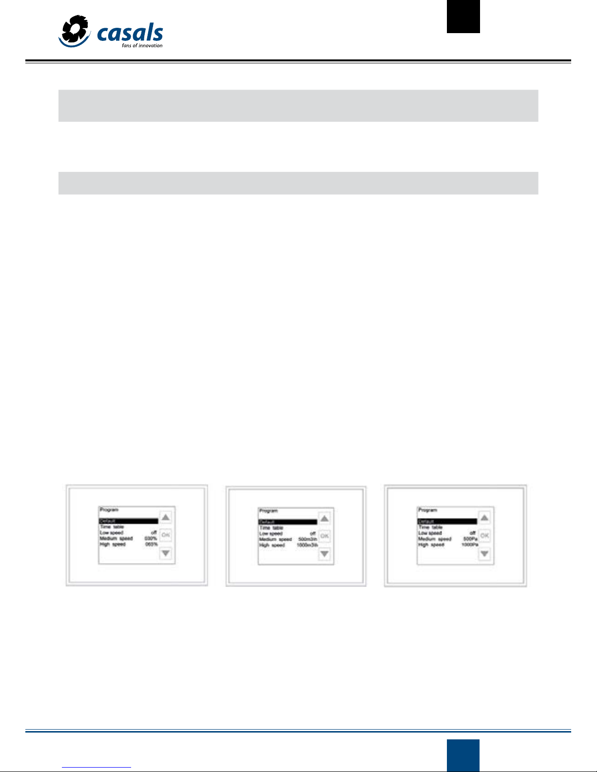
PROGRAM MENU: WEEKLY PROGRAMMING MANAGEMENT
This menu allows to manage the speed of the fans (in three levels) that are expressed in percentage for machines of variable speed, in pascals
for machines of constant pressure and in m3 / h for machines of constant flow. It is also possible to enable / inhibit air after-treatment (if present) in a different way for each day of the week.
Everything can be adjusted for different time slots (from 1 to 8 definable by the user with a resolution of 30 minutes). To access the programming management functions, select Program with the direction buttons pointing to it and press OK.
Program menu display with fan speed Program menu display with air low Program menu display with pressure
10
CV072018-1
DEFAULT
By selecting this menu item and pressing the OK button, the parameters for the management of the unit are automatically assigned the
preset values:
Program valid from Monday to Friday:
Program valid from Saturday to Sunday:
TIME TABLE
Time table Speed fans/ air flow/ pressure Air after-treatment condition: (ON enabled, OFF inhibited)
C1 00:00 -> 06:29 medium OFF
C2 06:30 -> 07:59 medium ON
C3 08:00 -> 11:29 low ON
C4 11:30 -> 12:59 High ON
C5 13:00 -> 17:59 low ON
C6 18:00 -> 21:59 high ON
C7 22:00 -> 00:00 medium OFF
C8 not used - -
TIME TABLE
Time table Speed fans/ air flow/ pressure Air after-treatment condition: (ON enabled, OFF inhibited)
C1 00:00 -> 07:29 medium OFF
C2 07:30 -> 07:59 medium ON
C3 08:00 -> 11:29 medium ON
C4 11:30 -> 12:59 high ON
C5 13:00 -> 17:59 medium ON
C6 18:00 -> 21:59 high ON
C7 22:00 -> 00:00 medium OFF
C8 not used - -
SPEED LEVELS
Low: Medium sp. OFF
Medium sp.: 030% if the unit is equipped with adjustable speed fans; 1 if the unit is equipped with three-
speed fans; auto if the unit has a CO2 sensor, relative humidity or if it is managed by an external
0-10V signal.
0200m s\h if the unit is of constant flow with cop \ cav kit. This value also depends on the factory
menu settings based on the performance of the unit.
010Pa if the unit is constant pressure with cop \ cav kit. This value also depends on the factory
menu settings based on the performance of the unit.
High speed: 065% if the unit is equipped with adjustable speed fans; 2 if the unit is equipped with three-
speed fans; auto if the unit has a CO2 sensor, relative humidity or if it is managed by an external
0-10V signal.
20000m s\h if the unit is of constant flow with kit cop\ cav. This value also depends on the factory menu settings based on the performance of the unit.

11
CV072018-1
TIMETABLE
By selecting this menu item and pressing the OK button you access the summary display of each day of the week, divided into 24 hours.
To change the settings of each day, simply select it, in the summary display screen, and press the OK button; At this moment the detail screen
of the selected day will be shown, in which the list of the eight possible time slots (C1-C8) appears, the day of the week in which it is being
operated is shown in the upper left part of the screen.
By selecting a time slot and pressing the OK button you can modify its content, in the time zone modification screen, in addition to the indication of the day in which you are operating (top left), the graphic summary of the programming valid for the whole day. The parameters that
can be modified are:
- Change / Change X: selecting this line and pressing OK you can change the time zone in which you are operating without returning to the
previous page: using the arrows, you can scroll through the different time zones (1-8), once the desired just press OK.
- Time / Hour hh.mm: selecting this line and pressing OK adjusts the start time of the current time slot: using the arrows increases (arrow up)
or decreases (arrow down) the schedule in 30 minute sections; Once you have located the desired value, press OK. This parameter can take a
value between the beginning of the previous time slot and the start of the next time slot.
- Fan speed / Speed. vent xxx: selecting this line and pressing OK adjusts the fan speed (or pressure / full-scale flow rate for machines without
cop / cav kit). The flow for units with constant flow or pressure for constant pressure units with kit cop / cav required for the current time slot:
using the arrows the three low, medium and high possible values are selected; located the desired value, press OK. These values correspond to
what is established according to the following section (Adjustment of speed levels).
- Post-heating / Poscalent. on / off: the parameter is visible only if the control is configured to manage an air after-treatment device; By selecting this line and pressing OK, it is possible to enable (on) or inhibit (off) the air after-treatment device. Using the arrows, the two possible
values, on and off, are selected. Once the desired value is found, press OK. When the timer mode is selected, it is visible on the screen if the ON
/ OFF timeout is enabled.
summary display
detail of one day a week
Modifiable parameters in the selected time slot
Selection of the time slot to be modified

12
CV072018-1
After carrying out the personalization of a day of the week according to your own needs (for example, Monday), you can copy the programming made on another day without having to repeat the whole procedure described above. In the summary display window of time slots,
select the day in which you want to copy the previously made programming (for example, Tuesday) and press OK. At this point the detail window of the time slots of the selected day is displayed. Using the down arrow, go through all the time slots until you reach the line Copy day (it
will appear after the last time slot C8): point to this line and press the OK button.
After accessing the Copy day page (indication visible in the upper left part of the screen), it is possible to select the day from which you want
to copy the programming. Once the election is selected (Monday in our example), press the OK button to confirm the copy and automatically
go to the simplified display of the slots (in our case we will have copied the programming on Monday in the day of Tuesday). This operation
can be repeated for other days of the week.
ADJUSTING SPEED LEVELS
To modify the default values for the three levels (low, medium and high) used for the weekly programming, it is necessary to access the main
page of the Program menu, with the arrows indicate the level to be modified (for example Low speed) and press the OK button. Using the
arrows you can go through the different possible values and, once you have located the desired value, confirm the selection by pressing the
OK button. The possible values for these three parameters are:
- off: stopped fans, accessed by keeping the down arrow pressed for a few seconds (off is below the minimum adjustable speed value).
- xxx%: for units with variable speed fans (or pressure / flow for machines without cop / cav kit) you can select a percentage value between
the minimum (set at the factory) and 100%.
- 1, 2 or 3: for units with three-speed fans you can choose between speeds 1, 2 or 3.
- auto: for units equipped with air quality probe, relative humidity or guided by an external 0-10V signal, the fan speed will be automatically
managed by one of these devices. It is accessed by holding the arrow up for a few seconds (auto is above the maximum adjustable speed
value).
- xxx m³ \ h: if the unit is in the constant flow version with the cav mounted kit, the desired value can be set in m³ / h of flow.
- xxx Pa: if the unit is in constant pressure version with the cop kit mounted, the desired value can be set in pressure pascals.
Disabled heating Post-heating enabled
Copy day function selection
Copy day: selection of the day to copy

13
CV072018-1
CLOCK MENU: CLOCK SETUP
This menu allows adjusting the day of the week and the current schedule for a correct management of the weekly schedule
ALARMS MENU: VISUALIZATION OF THE STATE OF ALARMS
If the control detects an anomaly, the latter is indicated in the main screen of the control with the intermittent display of a specific icon and
a red message at the top of the screen (Call service or Dirty Filters). If the alarm is detected when the screen is in standby mode, the screen
flashes intermittently (every 10 seconds approx.). Alarms in the pressure sensors are only available for machines with cav / cop kit.
Configuration of the day
Select the day / day line and press the OK button, the current day set will turn green; Scroll with the direction buttons to locate the desired day.
Press the OK button to confirm the selection, the day will change from green to blue.
Setting the time
Select the hours / hour line and press the OK button, the current time set will turn green; Scroll with the direction buttons to locate the desired
time. Press the OK button to confirm the selection, the time will change from green to blue.
Setting the minutes
Select the minutes line and press the OK button, Minutes will turn green; Scroll with the direction buttons to locate the desired minutes. Press
the OK button to confirm the selection, the word minutes will change from green to blue.
If the twinkle of an alarm is in progress, you can directly access the corresponding menu by touching the screen; otherwise, select Alarms on
the menu selection page and press OK. If the control is subjected to several units (master / slave mode), the unit to be monitored must be
selected (see Status menu); otherwise, the detail page of the alarms is accessed directly.
Alarm menu
twinkle of an alarm: outdoor air temperature probe

14
CV072018-1
ALARM LIST
Parameter Val State
Configuration
ok
The configuration is correct.
ko
The configuration of the digital inputs or hardware is incorrect. Check the ext.
Inputs in the factory menu. (eg if the same function is configured for several
inputs) or Hardware (Hw evo-compact-> el.water).
Communication ok The communication between the cards in the machine and the remote control
panel works correctly.
ko Problem in the communication between the cards and the remote panel:
1) check the electrical connections between the electronic board and the remote panel (see electrical diagram).
2) If the problem persists, check electrical connections between the two cards
(see electrical diagram).
3) If the problem persists, check the position of the dip switch on both cards.
For a unit: X540 only 1 = on; X531 only 2 = ON; X541 all off.
4) If the problem persists, replace the electronic card.
5) Check that the parameter Hw (factory menu) is correctly configured for the
unit in use.
Outdoor air temperature sensor works correctly.
Te (external)
ok Problem in the outdoor air temperature sensor:
ko 1) check the electrical connections of the temperature probe (see electrical diagrams).
2) If the problem persists, replace the temperature probe.
3) If the problem persists, replace the electronic card.
Tr (return)
ok Return air temperature sensor works correctly.
ko Problem in the return air temperature sensor:
1) check the electrical connections of the temperature probe (see electrical diagrams).
2) If the problem persists, replace the temperature probe.
3) If the problem persists, replace the electronic card.
Tx (expelled)
ok Expelled air temperature sensor works correctly.
ko Problem in the expelled air temperature sensor:
1) check the electrical connections of the temperature probe (see electrical diagrams).
2) If the problem persists, replace the temperature probe.
3) If the problem persists, replace the electronic card.
Ti (input)
ok Introduced air temperature sensor works correctly.
ko Problem in the air temperature sensor introduced
1) check the electrical connections of the temperature probe (see electrical diagrams).
2) If the problem persists, replace the temperature probe.
3) If the problem persists, replace the electronic card.
It is present only if the air after-treatment management is configured with
water coil (Factory menu).
Tw (water)
ok Temperature sensor in the water coil works correctly.
ko Problem in the air temperature sensor entered:
1) check the electrical connections of the temperature probe (see electrical diagrams).
2) If the problem persists, replace the temperature probe.
3) If the problem persists, replace the electronic card.

15
CV072018-1
Tw (water low)
ok It is present only if the air after-treatment management is configured with wa-
ter coil (Factory menu).
The temperature of the water leaving the coil is higher than a safety threshold;
there is no risk of freezing the water in the coil.
ko Risk of freezing the liquid in the water coil.
It is present only if the filter status alarm is configured with differential pressure
switch or depending on the hours of operation of the machine (Factory menu).
Filters
ok Clean filters.
ko It is only present if the fan status alarm is configured with differential pressure
switches, with tachometer signal from the fans or with DO of the fans (Factory
menu).
Fans/
ok Fans OK.
ko Possible failure in a fan. It is only present if the automatic speed management of
the fans with CO2 or CO2 sensor is configured -VOC2 (Installer menu).
CO
2
VOC
ok Probe OK.
ko Possible failure of the probe or the connection.
It is only present if the automatic speed management of the fans with relative
humidity sensor (Installer menu) is configured.
RH senso
ok Probe OK.
ko Possible failure of the probe or the connection.
It is only present if the fan speed management is configured with analog 0-10V
external signal (Installer menu).
Ext.signal
ok External signal source works correctly.
ko External signal not present (voltage at terminals equal to 0V):
1) check the electrical connections of the external source (see electrical diagrams).
2) if the problem persists, check the presence of the external signal (tester) with
values higher than 0V.
3) If the problem persists, replace the electronic card. It is only present if the
machine is in a constant flow version with control over the two flows.
FlowSupply
ok The pres sensor of drive works correctly.
ko Possible anomaly in the pres sensor of drive.
FlowExhaust
ok It is only present if the machine is in a constant flow version with control over
the two flows.
ko The pres sensor return function works correctly Possible anomaly in the pres.
sensor return.
Flow
ok It is present only if the machine is in a constant flow version with control over
a flow.
ko The pressure sensor works correctly Possible anomaly in the pressure sensor.
DpSupply
ok It is present only if the machine is in a constant pressure version with control
over the two flows.
ko The pres. sensor of impulsion works correctly Possible anomaly in the pres. sen-
sor of drive.
DpExhaust
ok It is only present if the machine is in a constant flow version with control over
the two flows.
ko The pres. sensor return function works correctly Possible anomaly in the pres.
sensor return.
Dp
ok It is present only if the machine is in a constant pressure version with control
over a flow.
ko The pressure sensor works correctly . Possible anomaly in the pressure sensor.

16
CV072018-1
Autominutes
ok It is only present if the automatic speed management of the fans with CO or
CO-VOC sensor (Installer menu) is configured or there is an excess of CO2 in the
environment. The sensor works correctly.
ko Possible anomaly in the sensor.
Antifrost
ok It is activated if the unit fails to exit the antifreeze mode of the exchanger within
2 minutes. The unit works correctly.
ko Two minutes have elapsed since the entry in antifreeze mode and the ejection
temperature has not risen again above 3C °. For speed management, the control stops the drive fan and adjusts the return fan to the maximum speed. For
resistance management, it stops both the impulsion fan and the resistance, the
return flow goes to the speed set in the control panel. For by-pass management, it stops the flow fan and leaves the by-pass in the current position.
Bypass off:
The bypass will remain closed regardless of the internal and external temperatures.
Bypass on:
The bypass will remain open regardless of the internal and external temperatures.
PARAM MENU: ADJUSTMENT OF USER PARAMETERS
The parameter menu is displayed only when the control detects that the conditions exist for which the current station should be selected. It
may be due to the winter / summer settings in the installer menu (see) or the presence of a cold water coil. If it is not displayed, the control
automatically proceeds to the management based on the outside temperature and return values. Modification of the values of the available
parameters is done by selecting the desired one and pressing the OK key; at this point the current value of the parameter turns green, to go
through the different possible values, use the arrows. If a dehumidification system is installed, the relative humidity threshold value can also
be adjusted in this menu.
Bypass configured in “All Season \ All SeasonM” mode and / or management of an element enabled for air after-treatment (Factory menu). For
the regulation, threshold values of the return temperature present in the installer menu are used (see Winter / Summer temperature) which
are compared with the effective values of outdoor temperature \ ambient. If the conditions for free-heating/ cooling persist, the by-pass is
adjusted accordingly according to the following diagram:
By-pass: summer
By-pass: winter
Open ( free heating)+ heating
Open ( free heating)
Open modulated (free cooling)
Open modulated (free cooling)+cooling
closed
closed

17
CV072018-1
Humidity (%)
This parameter is available only when a dehumidification system is planned. Represents the threshold value above which dehumidification is
enabled. The default value is 50%. Dehumidification can also be forced by a digital input.
INSTALLER MENU: CONFIGURATION OF INSTALLATION PARAMETERS
To access this menu, you need to enter a password (5678) to avoid inadvertent modification by non-expert users of parameters that could
compromise the correct operation of the installation.
To enter the password, press the down arrow so that the corresponding line is indicated, press the OK button and enter the first digit. Select
the desired value using the up / down arrows and press OK when you reach it.
Repeat the operation for the three remaining figures. If the password has been entered correctly, the installer menu is displayed; otherwise,
you return to the introduction page. To modify the parameters of this menu, select the desired one (scrolling with the up/ down arrows) and
press the OK button. The currently established value is shown in green, at this point it is possible to modify it using the arrows and pressing
OK to confirm the selection. The parameters related to the coefficients and flow/ pressure values are available only for machines with kit, the
display or not of such parameters is linked to the settings in the factory menu.
Bypass configured in universal mode (Factory menu), three values can be selected for the bypass parameter:
Automatic bypass:
A temperature range, comprised between TMIN and TMAX, is considered comfortable for the user; If the internal temperature (Tr) is within this
range, the bypass will remain closed. When Tr is out of this range (Tr> TMAX or Tr <TMIN) the control will open the bypass in case the external
temperature (Te) is within the comfort range (TMIN <Te <TMAX); otherwise, the bypass will remain closed.
Not defined or automatic
This parameter is available only when a dehumidification system is planned.
Through this you can enable (Yes) or inhibit (No) the dehumidification
system. It can be used, for example, in the winter season, if you do not want
to dehumidify.
digital input
insert password Installer menu

18
CV072018-1
PARAMETERS AVAILABLE IN THE INSTALLER MENU
Language
With this parameter you can select the language in which all the menus will be displayed (with the exception of the Factory menu, which will
always be displayed in English).
GB English display (default value)
FR Display in French
ES Display in Spanish
IT Display in italian
NL Display in Dutch
DE Display in German
HU Display in Hungarian
DK Display in Danish
PT Display in Portuguese
SI Display in Slovenian
Auto
With this parameter you can configure a device to regulate the fan speed automatically. For the connection of the device see the electrical
diagram.
ex signal The speed of the fans will be regulated by an external 0-10V analog signal (default value); if the external signal assumes a value equal
to 0V; the control will signal a problem of the external signal source. For units equipped with variable speed fans:
AutoMin% corresponds to the percentage of the input signal by which the fans must operate at the minimum speed.
AutoMax% corresponds to the percentage of the input signal by which the fans must operate at maximum speed.
For units equipped with three-speed fans:
SP. 1,2% = Automax% - AutoMin%+ AutoMin%
SP. 2,3% = 7 x (AutoMax% - AutoMin%) + AutoMin%
∆ = Automax% - AutoMin%
12
10
5
The values of SP.1.2% SP.2.3% and A depend on the values of the two parameters AutoMin% and AutoMax% according to the following:

19
CV072018-1
HR Sensor
The speed of the fans will be regulated by a relative humidity (RH) sensor with 0-10V output and linear characteristic between 0 and 100% RH
(0V correspond to 0% RH and 10V correspond to 100% RH); If the external signal from the HR sensor assumes a value equal to 0V, the control
will signal an alarm. See graphs of the signal parameter ext. In this case AutoMin% corresponds to the relative humidity value for which it is
considered optimal air quality, AutoMax% corresponds to the value of relative humidity for which the air quality is considered bad. A possible
dehumidification system can be managed by this sensor or, if for example this input is occupied by CO2, by another supplementary selected
in the factory menu.
CO
2
VOC
The speed of the fans will be regulated by a CO2 sensor (or CO2-VOC) with 0-10V output and linear characteristic between 0 and 2000 ppm
(0V correspond to 0 ppm and 10V correspond to 2000 ppm); if the external signal of the CO2 sensor takes a value equal to 0V the control will
signal an alarm. For units equipped with variable speed fans:
AutoMin ppm corresponds to the concentration of CO2 (CO2-VOC) for which air quality is considered optimal, AutoMax ppm corresponds to
the concentration of CO2 (CO2-VOC) for which air quality is considered poor.
For units equipped with three-speed fans:
SP. 1,2% = Automax ppm - AutoMin ppm + AutoMin ppm
SP. 2,3% = 7 x (AutoMax ppm - AutoMin ppm) + AutoMin ppm
∆ = Automax ppm - AutoMin ppm
12
10
5
The values of SP.1.2% SP.2.3% and A depend on the values of the two parameters AutoMin% and AutoMax% according to the following:
None (default value) is not provided for the use of any device for the automatic management of fan speed.

20
CV072018-1
AutoMax %
This parameter is available only if the auto parameter is set to ext. or HR sensor. It can take values between 1 and 100% (steps 1%) with the
limitation that AutoMin% <AutoMax%. For units equipped with variable speed fans:
If auto signal ext.
corresponds to the percentage value of the input signal by which the fans rotate at the maximum speed, above this value the fans remain
adjusted to the maximum speed. For example, the AutoMax value% 080 corresponds to an 8V input signal (80% of 10V).
If auto sensor HR
corresponds to the relative humidity value (in percentage) by which the fans rotate at the maximum speed, below this value the fans remain
adjusted to the maximum speed. For units equipped with three-speed fans, taking into account the second image of the external auto-signal
parameter, the values of SP.1.2% and SP.2.3% are set (nominal values in which the steps of the speed 1 to 2 and speed 2 to 3) you can obtain
the appropriate value to assign to the parameter:
AutoMin ppm
This parameter is available only if the auto parameter is set to CO2 VOC. It can take values between 0 ppm and 1980 ppm (steps of 20ppm) with
the limitation that AutoMin ppm <AutoMax ppm.
For units equipped with variable speed fans, corresponds to the concentration of CO2 (CO2-VOC), expressed in ppm, by which the fans turn at
the minimum speed; below this value the fans remain adjusted to the minimum speed. For units equipped with three-speed fans, taking into
account the second image of the auto CO2 VOC parameter, the values of SP.1.2% and SP.2.3% are set (nominal values in which the speed steps
are produced) 1 to 2 and speed 2 to 3) you can obtain the appropriate value to assign to the parameter:
AutoMax ppm
This parameter is available only if the auto parameter is set to CO2 VOC. It can take values between 20 ppm and 2000 ppm (steps of 20 ppm)
with the limitation that AutoMin ppm <AutoMax ppm For unit equipped with variable speed fans, corresponds to the concentration of CO
2 (CO2 -VOC), expressed in ppm , by which the fans rotate at maximum speed; above this value the fans remain adjusted to the maximum
speed. For unit equipped with three-speed fans, taking into account the second image of the auto CO2 VOC parameter, the values of SP.1.2%
and SP.2.3% are set (nominal values in which the speed steps occur 1 to 2 and speed 2 to 3) you can obtain the appropriate value to assign to
the parameter:
AutoMin% = 7 x SP.1,2% - 2 x SP.2,3%
5
AutoMax% = 8 x SP.2,3% - 3 x SP.1,2%
5
AutoMin ppm = 7 x SP.1,2% - 2 x SP. 2,3%
5
AutoMax ppm = 8 x SP. 2,3% - 3 x SP. 1,2%
5
AutoMin %
This parameter is available only if the auto parameter is set to ext. or HR sensor. It can take values between 0 and 99% (steps 1%) with the
limitation that AutoMin% <AutoMax% For units equipped with variable speed fans:
If auto signal ext.
corresponds to the percentage value of the input signal by which the fans rotate at the minimum speed, below this value the fans remain
adjusted to the minimum speed. For example, the AutoMin% 030 value corresponds to a 3V input signal (30% of 10V).
If auto sensor HR
corresponds to the relative humidity value (in percentage) by which the fans rotate at the minimum speed, below this value the fans remain
adjusted to the minimum speed. For units equipped with three-speed fans, taking into account the second image of the external auto-signal
parameter, the values of SP.1.2% and SP.2.3% are set (nominal values in which they occur).
the steps of speed 1 to 2 and speed 2 to 3) you can obtain the appropriate value to assign to the parameter:

21
CV072018-1
AutoMinutes
000 -> 240
This parameter is available only if the auto parameter is set to a value other than none. No (default value) there is no effect on the operation of
the system. It is a value expressed in minutes, it represents the interval of time elapsed since the signal of the external device for the auto mode
has reached, or exceeded, the value AutoMax% or Auto Max ppm, without descending below said value, above which indicates an anomaly in
the external device (CO2 probe, HR or external signal).
AutoOn %
000 ->100
This parameter is available only if the auto parameter is set to ext. or HR sensor and the digital output is set to auto cmp. Default value 050, is
expressed in%; for values of HR% measured by the relative humidity sensor (or for values of the external signal 0-10V in percentage) lower than
the set, the digital output changes state.
AutoOff%
000 ->100
This parameter is available only if the auto parameter is set to ext. or HR sensor and the digital output is set to auto cmp. Default value 050,
expressed in%; for values of HR% measured by the relative humidity sensor (or for values of the external signal 0-10V expressed in percentage)
higher than the adjusted one, the digital output returns to the normal state.
AutoOn ppm
0000 -> 2000
This parameter is available only if the auto parameter is set to CO2 VOC and the digital output is set to auto cmp. Default value 0500, expressed
in ppm; for ppm values measured by the CO2 probe lower than adjusted, the digital output changes state.
AutoOff ppm
0000 -> 2000
This parameter is only available if the auto parameter is set to CO2 VOC and the digital output is set to auto cmp. Default value 0500, expressed
in ppm; for ppm values measured by the CO2 probe above the adjusted one, the digital output returns to the normal state.
Bypass Tmin
12->18
This parameter is active only if the bypass management is set to Universal (Factory menu). Default value 15, expressed in degrees centigrade.
It is the minimum temperature value (Tmin) that the system will attend to bypass management in the case that Automatic Bypass is set in the
Parameters menu.
Bypass Tmax
20->30
This parameter is active only if the bypass management is set to Universal (Factory menu) .- Default value 22, in degrees centigrade. It is the
maximum temperature value (Tmax) that the system will attend to bypass management in case Parameter is set to Automatic bypass.
Hours filters
00000 -> 99999
This parameter is active when the jammed filters alarm is based on the hours of operation of the unit (Factory menu) Default value 02000,
in hours. Represents the number of hours of operation of the unit after which the dirty filter alarm will be triggered. To reset the alarm, the
installer must set the new limit at which the signaling of the alarm is desired (check current operating hours in the status menu, parameter
Vent hours):
Hours filters = Hours vent. + hours for new alarm
Regulation
Tr on-off
This parameter allows to modify, when there is air after treatment, the reference for the set point. Normally based on the return temperature
(on), changing the value to off becomes the intake temperature.

22
CV072018-1
Vel.max
055% ->100%
This parameter is available if the control is set to manage variable speed fans (Factory menu) Default value 100%, is the maximum speed of the
fans expressed as a percentage of the nominal value (reduction of the maximum speed). The maximum speed adjustable in the main window
will always be 100% even for Vel values. max. less than 100%, which changes is the minimum speed value adjustable by the end user:
VE = speed in percentage of the extraction fan with respect to the intake fan (see following parameter).
INT EXCESS= rounds to the next integer VMIN = minimum speed set in the Factory menu.
Step = discrete values of the adjustable speed values (5% adjustable to 1% by specific demand, Factory menu).
minimum speed = INT
EXCESS
VMIN x 100
x step
{
VMAX x step
VMAX = Vel.max x VE if VE ≤ 100
VMAX = Vel.max x 100 if VE ≥ 100
100
VE
(
(
Press. Max
This parameter is available only for constant pressure units t (Factory menu). 1000Pa.
DpEstr. =XXX%
DpIng
067%->150% .
This parameter is available only for constant pressure units with control over the two flows. Default value 100%, expresses, in percentage, the
desired ratio between the pressure of the extraction fan and the impulsion fan, allowing an imbalance between the pressures of the two flows
to be made.
Kp DpI
This parameter is only available for constant pressure units with control over the two flows (Factory menu). It is the value of the proportional
coefficient relative to the admission flow (default 0.40).
Tau DpI sec.
This parameter is only available for constant pressure units with control over the two flows (Factory menu). It is the integral time value relative
to the admission flow (default 0.30).
Kp Dp
This parameter is only available for constant pressure units with control over the two flows (Factory menu). It is the value of the proportional
coefficient relative to the return flow (default 0.40).
Tau Dp sec.
This parameter is only available for constant pressure units with control over the two flows (Factory menu). It is the integral time value relative
to the return flow (default 0.30).

23
CV072018-1
Caud.Extr.=XXX%
Caud.Ingr.
067%->150%
This parameter is available only for units adjusted to constant pressure with control over the two flows. Default value 100%, expresses, in
percentage, the desired ratio between the flow rate of the extraction fan and the supply fan, allowing an imbalance to be made between the
flow rates of the two flows.
Kp Port. In
This parameter is available only for constant flow units with control over the two flows (Factory menu). It is the value of the proportional coefficient relative to the admission flow (default 0.40).
Tau Caud. I sec
This parameter is available only for constant flow units with control over the two flows (Factory menu). It is the integral time value relative to
the admission flow (default 0.30).
Kp Caud. E s
This parameter is available only for constant flow units with control over the two flows (Factory menu). It is the value of the proportional coefficient relative to the return flow (default 0.40).
Tau Caud. E s
This parameter is available only for constant flow units with control over the two flows (Factory menu). It is the integral time value relative to
the return flow (default 0.30).
Kp Caudal
This parameter is only available for constant flow units with control over a flow (Factory menu). It is the value of the proportional coefficient
relative to the flow measured (default 0.40).
Tau Caud. s.
This parameter is only available for constant flow units with control over a flow (Factory menu). It is the integral time value relative to the
measured flow (default 0.30).
ImpostaZero Port
With this parameter, the pressure sensor can be reset. The operation must be carried out with the unit turned off; It is advisable to carry out it
periodically to correct possible reading errors.
Vent.estr.= XXX%
Vent.entrada
067%->150%
This parameter is available if the control is configured to manage variable speed fans. Default value 100%, expresses, in percentage, the desired
ratio between the speed of the extraction fan and the drive fan, allowing an imbalance between the two air flows to be made.

24
CV072018-1
WINTER TEMPERATURE / SUMMER TEMPERATURE
Through these parameters you can access the menus below to adjust the effective return temperature threshold values (Tr) for bypass or
base management for bypass management with air after-treatment. The summer / winter values coincide in order to have an optimal setting
for all seasons. In this way, if the post-cooling is not installed, the transition operation is also avoided by inhibiting the parameter menu (it is
shown only when necessary). The control automatically proceeds to inhibit inappropriate selections. With the function Temperat. Predef. the
default values are adjusted (if modified).
Ti (Entr.) Min
16->20INV.
16->24 EST.
This parameter is available in all cases (although air after-treatment is not foreseen). Default values 18 (winter) - 22 (summer), expressed in
degrees centigrade; it is the lower end of the interval in which the control maintains the temperature of the flow of driving air. If the bypass is
set at the factory as on-off below this value it will be closed, if it is modulating (only free cooling or free cooling) it will be regulated in it. It is
also used as a minimum reference for aftercare.
Ti (Entr.) Max
28->40
This parameter is available if the control is configured to manage an electric post-heating system or heating / cooling by modulating water.
Default value 30, is expressed in degrees centigrade; it is the upper end of the interval in which the control maintains the temperature of the
flow of driving air in heating or cooling mode.
DVenti 000%->100%
000 Pa
0000m3\h
0-1-2-3
Default value 0. Represents the value in percentage of fan speed to add to the set to obtain the desired increase during dehumidification. For
example, if the fan speed is 20% and this parameter is set to 30%, in
the moment when dehumidification is enabled, the speed goes to 50% (20 + 30). If the machine is configured to operate at constant pressure
or flow, this value is expressed in Pascals or in cubic meters per hour. The value to which to pass depends on the established full scale. For
3-speed units, it is expressed in a simple numerical form (0-1-2-3) corresponding to the subsequent increase in speed to be established.
Diagram regulation by-pass

25
CV072018-1
COMMUNICATION (ONLY CTRL-MAX2 IP TOUCH PANEL WITH MODBUS)
A version of the touch screen control that supports the Modbus TCP-IP protocol is available through an ethernet connector mounted directly
inside the panel or Modbus RTU via an RS485 additional interface card upon request. For wiring, see the section “Wiring the control panel”.
In this submenu, the installer menu, the communication parameters of the modbus protocol in use can be established.
Default
Restore factory settings.
Modbus
It allows to choose between the TCP-IP or RS485 protocol.
Address
It can be configured only for the RS485 protocol. Represents the address that you want to assign to the unit (default = 1).
Baud rate
It can be configured only for the RS485 protocol. It is the transmission speed that you want to assign to serial communication (default = 9600).
Stop bits
It can be configured only for the RS485 protocol. Represents the value of the stop bit that you want to assign to serial communication (default = 1).
Conn. to (s) 10sec
The read time of the modbus registers can be modified using this parameter. This value indicates the maximum time after which, if there is no
access to the accesses from the master device, the modifications made by modbus are restarted. It can be deactivated but for security reasons,
once the machine is turned off, the restart will be carried out as well.
IP0.IP1.IP2.IP3
Represents the IP address of the machine (default = 192.168.1.243 modifiable).
NM0.NM1.NM2.NM3
Represents the address of the subnet mask of the machine (default = 255.255.255.0 modifiable).
GW0.GW1.GW2.GW3
Represents the gateway address of the machine (default = 192.168.1.1 modifiable).
Reset
Each change is made effective by means of the reset or reset function, which prevents the machine from being switched on again.

26
CV072018-1
Specifications Modbus protocol
- MODBUS TCP-IP:
Transmission speed: 10/100 Mbit / s.
Automatic negotiation of transmission speed.
Auto -MDIX (automatic swap for crossed cables), disconnection after 10 sec without access to the registers (modifiable via MODBUS).
Maximum number of simultaneous connections: 8 Default address:
IP: 192.168.1.243 MASK: 255.255.255.0 LINK DOOR: 192.168.1.1
- MODBUS-RTU:
Transmission speed: 9600 bit / s.
1 stop bit, even parity, disconnection after 10 without access to the registers (modifiable via MODBUS) closing bridge of the rs485 card, to be
entered if the unit is the last device in the line.
Web server
Installed directly on the touch panel we have a web server that allows us to monitor the status of the machine and modify its parameters
through PC. Modifications made with web services are permanent and remain stored even if the unit is turned off. For the connection to the
web server to be correct, the first three fields of the IP address of the panel and that of the computer to which it is connected must match. For
example, if our address is 192.168.1.243, the address of the PC should be 192.168.1.xxx. To start the web server after connecting the network
machine, open your browser and type in the address bar: http \\ 192.168.1.243.
The main screen will appear as in the figure:
On the screen we find a reproduction of the typical touch panel screen, the differences are the variations that are made with the arrow buttons. You can increase or decrease the values of a unit by clicking on the button of an arrow; with the button of two arrows it can be increased
or decreased in several units. By means of the central button you can carry out the direct shutdown of the after-heating, fans and timer. The
modifications made are saved automatically after 5 seconds. The writing of the retention records via Modbus is disabled for 60 sec after each
modification made with the web server. To have a continuous update of the website, click on the “refresh on” button, it will go to “refresh
off” and the page will be updated every 5 sec. If the machine is equipped with a post-heating system we will also have the desired set point
temperature. Clicking on the Menu icon displays a list of available options, which are selected with the arrow keys. For the description of the
different menus, see the previous sections.
Parameters
Main screen web server
increase/decrease 1 unit
increase/decrease 10 units
Return temperature
Input temperature
Speed Buttons
Temperature
Expelled temperature
Timer

27
CV072018-1
Interaction table
The configuration parameters, set points, input signals, states and alarms are accessible as “retention registers” (word access 16 bits). BXX is the
XXth bit of a word (XX is a value of 00 to 15). R indicates that the word is only readable, R / W in turn indicates that the word is both readable
and writable. The R / W values are reset to the values set by the web server if the access time to the registers is exceeded or the unit is switched
off. The most significant bit is represented by the highest value, for example, between B00 and B15, the latter represents the most significant.
ADDRESS
WORD
ID
FORMAT R/W
DESCRIPTION VALUES AT IGNITION
OR TO DISCONNECT
CONFIGURATION
1 SW_PN_0 SW TYPE 0
R
MODEL SW
2 SW_PN_1 SW TYPE 1
R
MODEL SW
3 SW_PN_2 SW VER 0 (AAMM)
R
VERSION SW
4 SW_PN_3 SW VER 1 (DDPP)
R
VERSION SW
5 REMOTE_CONTROL
B00: R/W DEVICE_RESET (1=RESET)
BIT NOTICE RESET CARD:
BY DEFAULT = 1, IF IT IS ADJUSTED TO 0 AND AFTER IT IS IN 1 IT MEANS THAT THERE HAS BEEN A
RESET OF THE CARD.
B01: R TERMINAL_ACTIVE (1=ACTIVE)
TERMINAL CONNECTION.
B02: R TERM_RS485_ACTIVE (1=ACTIVE)
TERMINAL CONNECTION. RS485.
B04: R/W CONNECTION_LOST 1=LOST)
BIT NOTICE DISCONNECT: DEFAULT = 0, IF BELOW
IT IS IN 1 IT MEANS THAT THERE HAS BEEN A
DISCONNECT
B13: R/W CMD DEVICE RESET (1=RESET)
DEFAULT = 0; IF IT IS ADJUSTED TO 1 THE CARD
RESTS
B14: R/W WR_APP_CONF (1=WRITE PENDING)
BIT TO MEMORIZE THE CONFIGURATION IN NOVRAM (YES = 1)
B15: R/W WR_SP (1=WRITE PENDING)
BIT TO MEMORIZE IN NOVRAM THE ADJUSTMENT
POINTS (YES = 1)
20 PARAMETER_FLAGS
B00- 01: R/W SEASON
0: SEASON_ND
1: SEASON_WINTER
2: SEASON_SUMMER
B02- 03: R/W BYPASS
0: BYPASS_AUTO
1: BYPASS_OFF
2: BYPASS_ON
R/W
ADJUSTMENT BYPASS STATION (B00 B01)
0=NON DEF.\AUTO
1=WINTER W
2=SUMMER
UNIVERSAL(B02 B03)
0=NON DEF.\AUTO
1=OFF
2=ON
24 UNIT_1_MAX_FILT_
HOURS
0- 199 (500h) R/W THRESHOLD ALARM FILTERS HOURS UNIT 1
25 UNIT_2_MAX_FILT_
HOURS
0- 199 (500h) R/W THRESHOLD ALARM FILTERS HOURS UNIT 2
26 UNIT_3_MAX_FILT_
HOURS
0- 199 (500h) R/W THRESHOLD ALARM FILTERS HOURS UNIT 3
27
UNIT_4_MAX_FILT_
HOURS
0- 199 (500h) R/W THRESHOLD ALARM FILTERS HOURS UNIT 4

28
CV072018-1
CONTROLS
51 SPEED_SET_POINT
FOR VARIABLE SPEED VERSION: 0- 100 % ;
101=TIMER ; 102=AUTO. FOR THREE SPEED
VERSION:
1-2-3 ; 4=TIMER ; 5=AUTO
FOR CAV\COP UNITS : PASCAL-M3\H
TIMER(65534) AUTO(65535).
R/W
SPEED ADJUSTMENT POINT
FANS. FOR VAV UNIT:
0-100%; 101 = SCHEDULE PROGRAM;
102 = AUTO.
FOR 3 SPEED UNITS: 1-2-3 4 =
SCHEDULE PROGRAM;
5 = AUTO.
FOR CAV UNIT \ CP: PASCAL-M3 \ H
TIMER (65534)
52
TEMPERATURE_SET_
POINT
OFF(<=48) or 50- 300 (0,1 °C) R/W
TEMPERATURE ADJUSTMENT POINT
(ONLY IF THERE IS POSTPARTING OF AIR)
53 TIMER 0- 14400 (sec.) R/W
MAXIMUM SPEED TIMER FANS
54
SPEEDS REMOTE
CONTROL
B00- 06: REMOTE_SUPPLY_SPEED 0- 100%
B07: SUPPLY_SPEED_REMOTE_CONTROL
0: OFF
1: ON
B08- 14: REMOTE_ EXHAUST_SPEED 0- 100%
B15: EXHAUST_SPEED_REMOTE_CONTROL
0: OFF
1: ON
R/W
PARAMETERS TO UNLINK THE
SPEED OF CONTROL FANS AND CONTROLLED
THEM INDEPENDENTLY.
IT IS ENABLED BY MEANS OF
THE BITS 07 (IMPULSION) AND 15 (RETURN).
THROUGH 00-06 AND 08-14 ADJUST
THE SPEED OF EACH
55 RHUMIDITY_SET_
POINT
S0-100% R
HUMIDITY ADJUSTMENT POINT WHEN
THE FUNCTION OF DEHUMIDIFICATION
81
TEMP_E
(0,1 °C)
R
TEMP. EXTERNAL
82
TEMP_R
(0,1 °C)
R
TEMP. RETURN
83
TEMP_X
(0,1 °C)
R
TEMP. EXPELLED
84
TEMP_I
(0,1 °C)
R
TEMP. ADMISSION
85 TEMP_W
(0,1 °C)
R
TEMP. WATER BATTERY

29
CV072018-1
86 STATUS_FLAGS
DIGITAL INPUT:
R
ESTADO ENTRADA DIGITAL (1=ACTIVO):
B00: BYPASS BYPASS STATUS: 1 = OPEN; 0 = CLOSED
B01: SUPPLY_SPEED_REM_CONT_ACTIVE ENABLING CONTROL
INDEPENDENT IMPULSION FAN
ACTIVE
B02: EXHAUST_SPEED_REM_CONT_ ACTIVE ENABLING CONTROL
INDEPENDENT FAN RETURN
ACTIVE
B03: DEHUM_ON ACTIVE DEHUMIDIFICATION
B04: NOFROST_ACTIVE ANTIFREEZE STATE
B05: EXT_DI_HUMIDITY STATE DIGITAL ENTRY: HUMIDITY
B06: EXT_DI_PIR_MIN STATE DIGITAL ENTRY: PIR
B07: EXT_DI_REMOTE_OFF STATE DIGITAL ENTRY: REMOTE
B08: HEAT\COOL_1 STATE 1 POSCALENT / REFRIG.
B09: HEAT_2 STAGE 2 POSCALENT.
B10: TEMP_WATER_LOW ANTIFREEZE STATE WATER BATTERY
B11: EXT_DI_SUMMER STATE DIGITAL ENTRY: STATION
B12: EXT_DI_FIRE STATE DIGITAL ENTRY: FIRE
B13: EXT_DI_WATER_NOFROST ANTIFREEZE WATER BATTERY
B14: EXT_DO_AUTO_COMPARE DIGITAL OUT STATUS: AUTO COMPARE
87 SPEED_C_VALUE
IF FANS_FAIL_TACH (REG 7 –B08) IS SET TO
1 RPM, OTHERWISE %
R
SPEED FAN IN RETURNS OR PERCENTAGE (SEE
REGISTER 7- B08)
88 SPEED_D_VALUE
IF FANS_FAIL_TACH (REG 7 –B08) IS SET TO
1 RPM, OTHERWISE %
R
SPEED FAN RETURN RETURNS OR PERCENTAGE
(SEE REGISTER 7- B08)
89 AUTO_INPUT_VALUE % R
PERCENTAGE READING VALUE: PROBE
AIR QUALITY (=% 2000 PPM) HUMIDITY
EXTERNAL SIGN
90 ALARMS 1
B00: COMM_X540_FAIL
R
COMMUNICATION ERROR CARD X540.
B01: TE_FAIL FAULT LINE EXTERNAL PROBE.
B02: TR_FAIL FAULT LINE RETURN PROBE.
B03: TX_FAIL FAULT LINE EXPULSION PROBE.
B04: FILTERS_FAIL ALARM FILTERS STAMPED.
B05: FANS_FAIL FAN FAILURE.
B06: AUTO_FAIL FAILURE PROBE AIR / HUMIDITY.
B07: TI_FAIL FAULT LINE ADMISSION PROBE.
B08: COMM_X531_FAIL COMMUNICATION ERROR CARD X531.
B09: TW_FAIL ICE ALARM WATER BATTERY.
B10: TW_LOW ALARM TIME WAITING PROBE QUALITY
AIR / MOISTURE.
B11: AUTO_TO_FAIL COMMUNICATION ERROR CARD
X570 IMPULSION.
B12: COMM_X570_DPS_FAIL COMMUNICATION ERROR CARD X570
RETURN.
B13: COMM_X570_DPE_FAIL PRESSURE SENSOR FAILURE IMPULSION.
B14: DPSUPPLY_FAIL PRESSURE SENSOR FAILURE RETURN.

30
CV072018-1
91 DP _SUPPLY B15: DPEXHAUST_FAIL
FOR UNITS COP = VALUE OF
PRESSURE SIDE IMPULSION FAN
92
DP
_EXHAUST
(Pa)
FOR UNITS COP = VALUE OF
PRESSURE SIDE FAN RETURN
93 FLOW_SUPPLY (m3/h)
FOR CAV UNITS = FLOW VALUE FLOW VALUE.
IMPULSION
94 FLOW_EXHAUST (m3/h)
FOR CAV UNITS WITH DOUBLE PROBE = FLOW
VALUE SIDE VALUE. RETURN
95 FAN_HOURS_H (65536 h)
OPERATING TIME FANS (FAN_HOURS_H * 65536+
FAN_HOURS_L)
96 FAN_HOURS_L (h)
97 ALARMS 2
B00: CONFIGURATION_FAIL
B01: ANTI ICE_FAIL
CONFIGURATION ERROR ANTIFREEZE ALARM
98 PRE_HEAT (%)
PERCENTAGE MODULATING PRE-HEATING REGULATION.
99 POST_HEAT (%)
PERCENTAGE REGULATION POST-HEATING MODUL.
UNIT_2_DATA
101 TEMP_E
R
UNIT_4_DATA
141 TEMP_E
R
1001
1002
1003
TIME_TABLE_SPEED_0
TIME_TABLE_SPEED_1
TIME_TABLE_SPEED_2
IF CONFIG_FLAGS_1.MODULE_FLAG = 0 :
0-1-2-3) OR AUTO(5)
IF CONFIG_FLAGS_1.MODULE_FLAG = 1
and PRESS_FLOW_REG_PRESENT = 0 :
0-100% OR AUTO(102)
IF CONFIG_FLAGS_1.MODULE_FLAG = 1
AND PRESS_FLOW_REG_PRESENT = 1 :
0 - SPEED_RANGE OR
AUTO(65535)
RW
SELECTION OF SPEED A
ASSOCIATE TO THE TIME FRAME
1017
1024
MONDAY-CHANGE-0
/ 7
B00-10: TIME - MINUTES
B11-13: SPEED SELECTION :
000: TIME_TABLE_SPEED_0
001: TIME_TABLE_SPEED_1
002: TIME_TABLE_SPEED_2
B14-15: TEMPERATURE REG. ENABLE
00: OFF
01: ON
RW
ADJUST TIME IN MINUTES FROM
00.00 (EJ.:60=1.00)
SELECTION OF SPEEDS
TEMPERATURE SELECTION
1025
1032
TUESDAY-CHANGE-0
/ 7
RW AS THE PREVIOUS
1033
1040
WEDNESDAY-CHANGE-0 / 7
RW AS THE PREVIOUS
1041
1048
THURSDAY-CHANGE-0
/ 7
RW AS THE PREVIOUS
1049
1056
FRIDAY-CHANGE-0 / 7 RW AS THE PREVIOUS
1057
1064
SATURDAY-CHANGE-0
/ 7
RW AS THE PREVIOUS
1065
1072
SUNDAY-CHANGE-0
/ 7
RW AS THE PREVIOUS

31
CV072018-1
SERVICE DATA
8502 BAUD RATE
(100 bit/s) RW DEFAULT=96
8503
TIMEOUT
(sec.)
RW
TIME OF DISCONNECTION BY
DEFECT = 10 SEG.
65535 DISABLED THE CONNECTION IN
CASE OF ABSENCE OF READING
THE REGISTERS
8559
PASSWORD RW
INSTALLER: 5678 ENTER
FOR MODIFICATIONS MENU
INSTALLER
INSTALLATION
The installation must be carried out by specialized personnel. For optimal operation, the remote panel should be fixed to an internal wall at an
approximate height of 1.5 m from the ground, away from heat sources (radiators, stoves, etc.) and should not be exposed to sunlight direct It
should not be installed near doors that could damage the electronics when they closed.
WIRING CONTROL PANEL
Connect the power to the terminals indicated with 24V and G respecting the correct polarity. Connect the BUS to the terminal indicated with S.
The use of a shielded cable with sections of at least 0.3 mm is recommended. In case of communication errors, check the connections between
the remote panel and the electronic card. Always use a shielded at least 3x0.3mm cable for a possible RS485 card.
CONTROL FEATURES
Power supply: 9/30 VDC 250mW, working temperature between 0 and 50 ° C; storage temperature between -20 ° C and 70 ° C.
WARRANTY CONDITIONS
The warranty period of 2 years (24 months) begins with the receipt of the device, the date of receipt must be checked on the purchase invoice.
In the period covered by the warranty, the manufacturer repairs all defects arising from manufacturing errors or material defects free of charge.
At its discretion it will replace defective parts or entire appliances. Any other request for guarantee services is excluded. The manufacturer also
declines all responsibility for subsequent damages.
The material claimed as defective must be sent to the manufacturer through the distributor, accompanied by the detailed description of the
defect completed by the distributor. The customer is responsible for shipping the goods. The repair is sent by the manufacturer. In no case
does the manufacturer respond for defects caused by improper use not in accordance with the manual of use provided and by natural events
such as lightning, floods, earthquakes, fires, etc. It also declines any responsibility for repairs or modifications made to the devices by people
outside the manufacturing company.
Remote panel: rear view
Tcp-ip connection / additional card

32
CV072018-1
DIMENSIONS (mm)

33
CV072018-1
ASSEMBLY (mm)
Insert two supports to the right and left of the panel
Push the support upwards and the panel down
until the panel is completely fixed in the support
Place the panel on the stand
 Loading...