


www.casals.com
CV072018-1
CEPHIRUS-2
USER MANUAL AND INSTALLATION
2
CV072018-1
INDEX
SECURITY RULES AND MARKING CE
GENERAL RULES
MAINTENANCE
EQUIPMENT WARRANTY
CONDITIONS OF INSTALLATION
RESIDUAL RISKS
SIGNALS PLACED ON THE MACHINE
- Prohibition signs
- warning information signs
- identification signs
RECEPTION OF THE MERCHANDISE
DISPLACEMENT
STORAGE
PROLONGED STOP
START UP
ASSEMBLY AND DISASSEMBLY
ELIMINATION
WIRING DIAGRAMS
CONFIGURATIONS
CONDENSATE BOARD
ACCESSORIES - CUT SWITCH
ACCESSORIES - PRESSURE SWITCH
ACCESSORIES - CONSTANT AIR FLOW
ACCESSORIES - CO
2
CONTROL
ACCESSORIES - WATER COIL
ACCESSORIES - ELECTRICAL COIL
RESOLUTION OF PROBLEMS
DECLARATION OF CONFORMITY
p. 3
p. 3
p. 3
p. 4
p. 5
p. 5
p. 5
p. 6
p. 6
p. 6
p. 6
p. 6
p. 6
p. 6
p. 7
p. 8
p. 9
p. 9
p. 10
p. 10
p. 12
p. 14
p. 14
p. 16
p. 17

3
CV072018-1
CEPHIRUS-2
SECURITY AND MARKING STANDARDS “CE”
Our R & D department is concerned with achieving efficient products in compliance with the current “safety standards”. The rules and
recommendations set out below mainly reflect what is in effect in safety material and therefore are mainly based on compliance with the
general rules. Therefore, we strongly recommend all the people who manipulate the machine to follow the rules of accident prevention in
their place and in their country. Casals ventilation is exempt from any liability for any damage caused to people or property arising from
non-compliance with safety regulations, as well as any changes made to the product.
The CE marking and the relative declaration of conformity certify compliance with applicable Community standards. Products that are not
marked on the CE plate must be completed by the buyer who must then certify the entire plant, thus providing the certificate of conformity.
The machines meet the requirements of:
- Machinery Directive 2006/42 / CE.
- Low voltage directive 2014/35 / CE.
- With the Electromagnetic Compatibility Directive 2014/30 / CE.
- Ecodesign Directive 2009/125 / CE.
GENERAL RULES
Safety guards should not be removed if it is not due to absolute need for work; in which case appropriate measures must be taken that
must be taken immediately in the event of possible danger.
All maintenance work (ordinary and extraordinary) must be carried out with the machine stopped, electrical power, pneumatic etc ... disconnected. To avoid the danger of accidental insertion, stick on electrical panels, control units and control consoles
warning signs with the words “Warning: command excluded for maintenance in progress”. Before connecting the power cable to the terminal board verify that the line voltage is suitable for that shown on the machine’s plate, pay attention to the labels placed on the product; if
time goes by they should become illegible and they would have to be replaced.
The device must not be used by people (including children) whose physical, sensory or mental abilities are reduced, or with lack of experience or knowledge, unless they have been able to benefit, through the intermediation of a responsible person in their security, surveillance or instructions on the use of the device. Children should be checked to prevent them from playing with the device.
MAINTENANCE
The maintenance staff, in addition to having to observe the current legal provisions on accident prevention, must comply with the instructions shown below:
- Wear appropriate safety clothing.
- Use soundproof headphones when the noise exceeds the allowed limit.
- Verify the existence of an interlock that foresees the start-up of the machine by other people.
These heat recovery systems lack the maintenance periodically to perform correctly the function for which they were designed. The frequency with which maintenance is performed depends on the characteristics of the environment in which the device is inserted and the
number of hours of operation, so what is indicated below should be seen as guidance.
Fan
Operations to be carried out:
• Check if there are no foreign bodies inside the module.
• Check that all screws are tightened to avoid unwanted vibrations.
• General interior cleaning.
Maintenance interval: half-yearly
Filters
Operations to be carried out:
• Check if there are no foreign bodies inside the module.
• Check that all screws are tightened to avoid unwanted vibrations.
• Check if there are no cuts in the filter mat.
• Check the clogging status of the filters (clean or replace if necessary).
• General interior cleaning.
Maintenance frequency: monthly

4
CV072018-1
Heat recovery
Operations to be carried out:
• Check if there are no foreign bodies inside the module.
• Check that all screws are tightened to avoid unwanted vibrations.
• Check the condition and fixing and cleaning of the recovery element.
• General interior cleaning.
Maintenance interval: half-yearly
Water coil
Operations to be carried out:
• Check if there are no foreign bodies inside the module.
• Check that all screws are tightened to avoid unwanted vibrations.
• Check the connections to the battery.
• Check and clean (if necessary and with care not to cause damage) the fins of the batteries.
• If there are deformed fins, place them in the correct position with a suitable “comb”.
• General interior cleaning
Maintenance frequency: annual
EQUIPMENT WARRANTY
Casals Ventilation warrants this product against all manufacturing defects for a period of two (2) years from the date of purchase.
The service under warranty, will only be paid by presenting the purchase receipt, which shows that the machine is within the warranty
period. If, during the guarantee period, the product resulting from recognizing the problems of manufacturing defects, Casals ventilation
or its authorized technical services, shall, to the free repair on site or (according to the criteria of Casals ventilation) to replace the product
or make available to the customer for the replacement of defective components according to the following conditions. Casals ventilation
reserves the right, (at its own discretion) to replace the components of defective products or low-value products, both components or new
products, such as components or recycled products.
Warranty exclusions
• Pieces of natural wear.
• Parts subject to deterioration or breaking, for example belts, filters, fuses, etc.
• Failures caused by misuse, neglect, negligence, atmospheric discharges, floods, humidities, falls, crashes, accidents and transportation.
• Failures caused due to the use of equipment for purposes other than those foreseen.
Failures caused as a result of manipulation, change or repair of equipment by unauthorized persons or technical services or due to the use of
inappropriate parts or accessories.
Faults caused due to incorrect or illegal installation (voltage, water pressure or other), power anomalies, non-compliance with the instructions.
• Wear or aesthetic deterioration, resulting from the use, changes in tones, oxidation or corrosion of the device or its components.
• A possible repair does not result in the continuation of the warranty nor will it entitle any compensation.
The guarantee does not apply every time ...
• The type plate of the equipment is tampered with or tampered with.
• False data is provided.
• Do not accompany the equipment with the purchase document.
• The equipment is manipulated, changed or repaired by unauthorized persons or technical services.
• Verification / maintenance operations are not carried out or are carried out by unauthorized technicians.

5
CV072018-1
- PROHIBITION SIGNALS
- Do not repair or adjust during motion.
- DANGER AND INFORMATION SIGNALS
- Attention to the presence of electric current.
- Automatic start Danger.
- Attention to the instruction manual.
- Grounding the machine.
- PRODUCT MARKING
CONDITIONS OF INSTALLATION
The installation inside or outside buildings with an ambient temperature between -15 ° and + 50 ° C
It should be avoided:
- Areas near heat sources, steam, gas or flammable liquids and / or explosives, especially dusty areas, proximity to water sources such as
tanks, showers or swimming pools. Do not touch the appliance with wet or damp hands or feet. Do not leave the device exposed to atmospheric agents.
Must be:
- Use the device only for the use for which it has been expressly manufactured. The manufacturer is not liable for possible damages arising
from improper or incorrect uses.
- Consider an area where the air drive and the noise of the unit do not cause discomfort to neighbors.
- Consider a position that respects the minimum spaces (as indicated in this manual).
- Consider a position that does not obstruct steps or entries.
- The degree of protection of the unit is IP20.
In case of installation abroad:
- Place the unit in a place protected from atmospheric agents.
- Use the corresponding rain protection cover (if necessary together with the corresponding protection hoods with net). In this case, the
degree of protection becomes IP22.
RESIDUAL RISKS
The risk analysis of the products has been carried out according to the Machinery Directive (Annex I of Directive 2006/42 / EC). This manual
contains the information for all the exposed personnel in order to prevent possible damages to people and / or things due to residual risks.
SIGNALS PLACED ON THE MACHINE
Various signaling pictograms may be present on the machine, which must not be removed. This signals are divided into:

6
CV072018-1
RECEPTION OF THE MERCHANDISE
Each product is checked carefully before shipment. At the time of reception, check that the product has not been damaged during transport; otherwise, communicate the incident to the carrier. The carrier is responsible for possible
damages derived from transportation. The products are packed in pallets and fixed to it by strips and protective film, or in self-supporting
cardboard boxes, properly fixed to the pallet.
DISPLACEMENT
Before moving the product, make sure that the medium used has adequate capacity. For lifting, use forklifts, lifting the pallet. The maximum
hand lift is specified in the 89/391 / EEC standard and later. It is generally acceptable
a weight of 20 kg below the back but above ground level.
STORAGE
Store the unit in a sheltered place, without excessive humidity and not subject to strong temperature fluctuations, in order to avoid the
formation of condensation inside the unit. Storage is not recommended for a period longer than one year. If more than one year is stored, it
is necessary to check the free rotation of the bearings before installation (turn the turbine by hand).
PROLONGED STOP
In case of prolonged shutdown, with the unit connected to the ventilation system, close the suction / discharge ducts and periodically
check the absence of humidity inside the machine. In case of moisture formation, dry it immediately.
START UP
Before commissioning, it is advisable to carry out some checks (follow the safety instructions set out in the DISMOUNTING AND ASSEMBLY
section):
- Make sure that there is no condensation inside the unit, and if necessary dry it before putting the unit into operation.
- Check the status of the filters.
- Make sure that the interior of the product has no foreign bodies and that all the components are fixed in their seats.
- Manually test that the turbine does not rub against the suction mouth of the machine.
- Check that the inspection gate is closed.
ATTENTION:
If the mouths of a fan are not properly holed, a suitable protection net must be provided. Check the electrical ground connection. The
electrical connection must be made by qualified personnel.
DISASSEMBLY AND ASSEMBLY
Before starting any operation, make sure that the product is not in operation and can not be fed accidentally or accidentally, and that the
fans are stopped. The disassembly and the corresponding assembly are extraordinary maintenance operations and must be carried out by
qualified personnel.
ELIMINATION
In accordance with the Directive of the European Parliament 2012/19 / EU on waste electrical and electronic equipment (WEEE) “.
The crossed-out wheeled bin symbol on the appliance or on the packaging indicates that the product, at the end of its useful life, must be
disposed of separately from the other waste to allow proper treatment and recycling. The user must, therefore, deliver
free of charge the device, when it reaches the end of its useful life, to the corresponding local centers for selective collection of electrical
and electronic waste, or return it to the distributor according to the following modalities:
- For devices of very small size, or with an exterior side of no more than 25 cm, free delivery without obligation of purchase is foreseen in
the stores with an area of sale of electrical and electronic devices superior to 400 m2. For stores with inferior surfaces, this modality is optional.
- For appliances with dimensions greater than 25 cm, delivery is foreseen in all the points of sale in the 1-for-1 mode, that is, the delivery
to the distributor may only be made at the time of purchase of a new equivalent product, in reason of one to one. The adequate selective
collection for the subsequent delivery of the discarded device to recycling, treatment and compatible environmental elimination, helps to
avoid possible negative effects on the environment and health and favors the reuse and / or recycling of the materials that make up the
device . The illegal elimination of the product by the user supposes the application of the sanctions foreseen by the current legislation.

7
CV072018-1
WIRING DIAGRAMS
The ventilators are one of the vital components for the correct functioning of Casals ventilaión recovery units, so their correct connection
must be guaranteed in accordance with the following diagrams presented;
green/yellow
terra
green/yellow
terra
blue
neutral
blue
neutral
Phase
gray
gray
phase
TT
L N
N
N
C
L1
L1
black white red
CEPHIRUS-2 600
CEPHIRUS-2 1500/2100/3500/4800 CEPHIRUS-2 6400/7000
CEPHIRUS-2 900
L2
L3
L1
L2
L3
L1
black
red
white
gray
brown
blue
purple
protection
HIGH SPEED
LOW SPEED
8
CV072018-1
A
B
C
D
EF
GH
I
JKL
MN O
P
CEPHIRUS-2 & CEPHIRUS-2 EEC HORIZONTAL
Aire nuevo
Aire extraido
A
FV
AV BV CV
DV EV
B
GV
C
D
EF
GH
I
JKL
MN O
P
CEPHIRUS-2 & CEPHIRUS-2 EEC HORIZONTAL
CEPHIRUS-2 EEC VERTICAL
Aire nuevo
Aire extraido
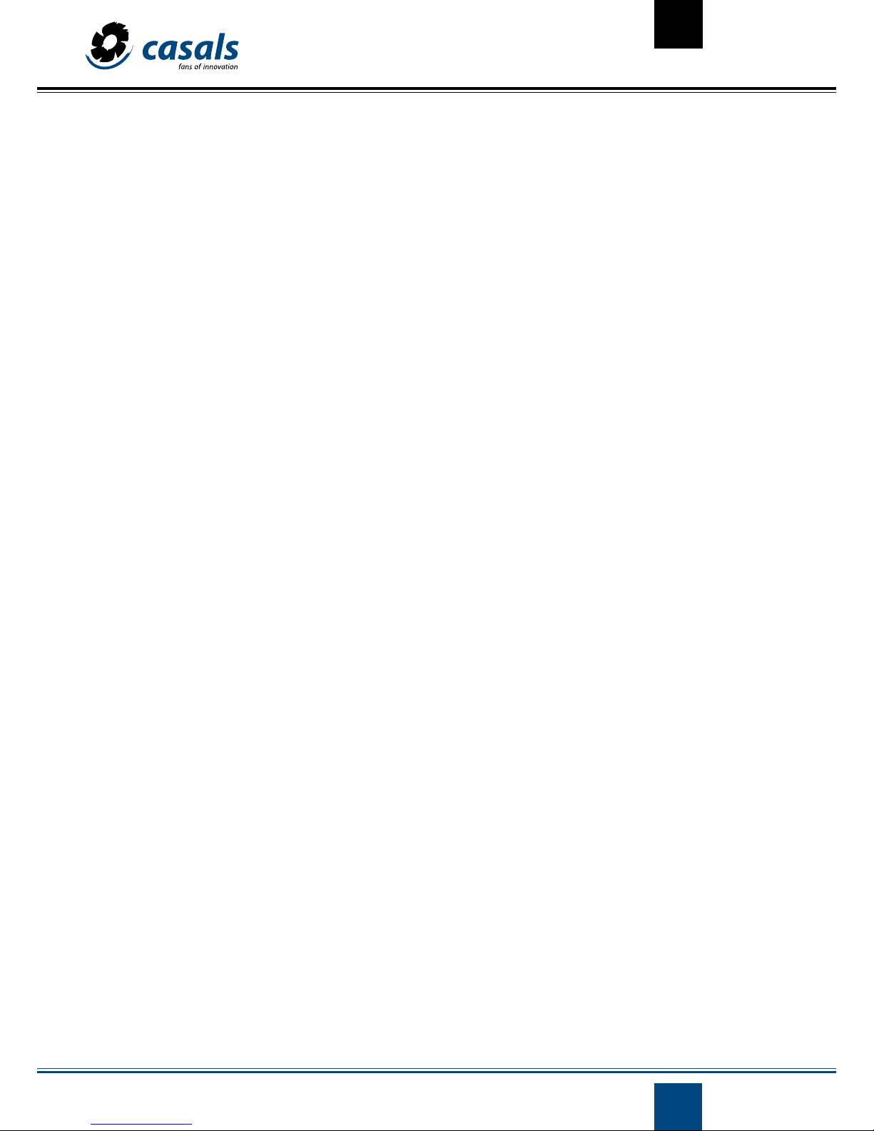
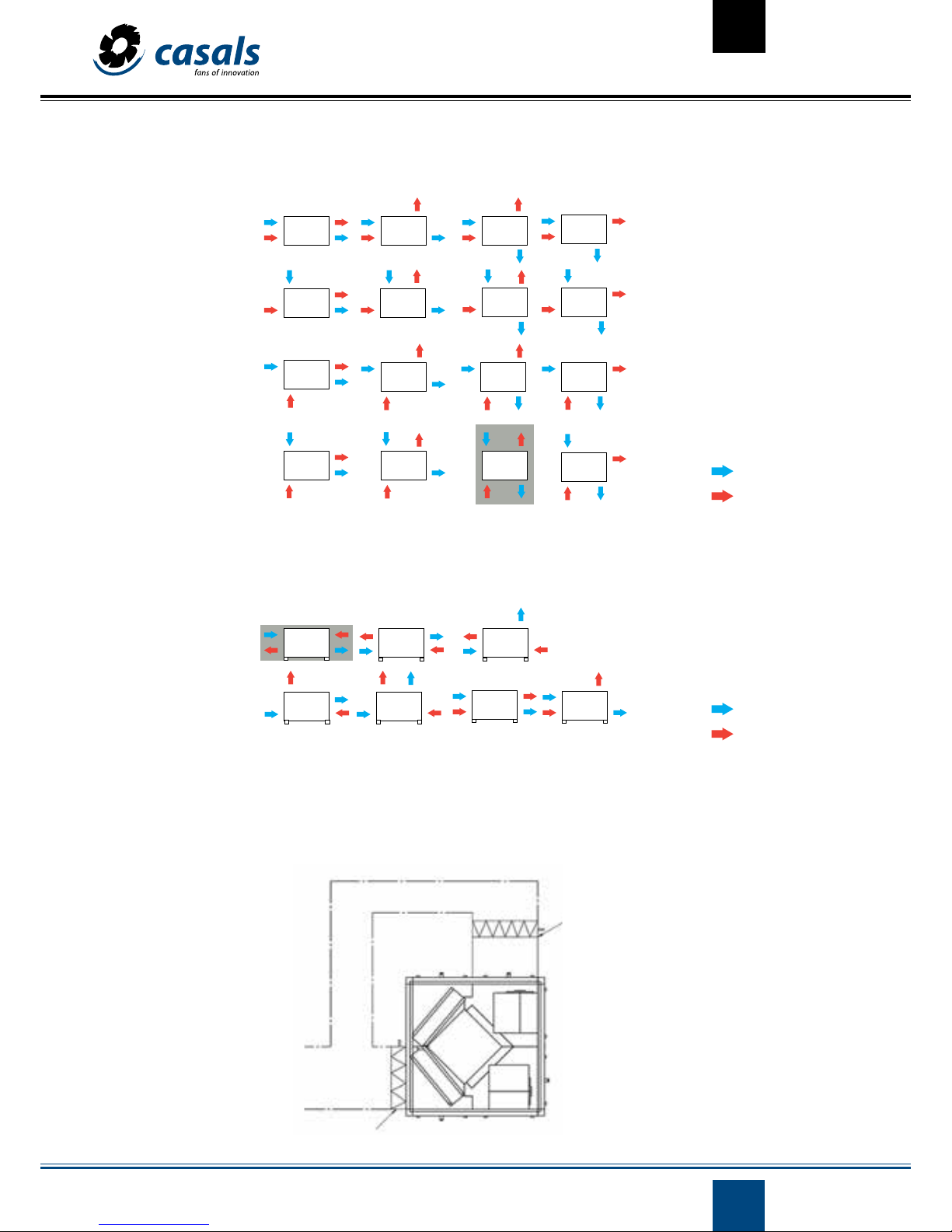
CONFIGURACIONES
Horizontal version with coil and Control
CEPHIRUS-2 & CEPHIRUS-2 EEC HORIZONTAL
Vertical version with control
(coil module mounted when purchased separately from the product catalogue, see for more information).
CEPHIRUS-2 & CEPHIRUS-2 EEC HORIZONTAL
Nota: Versiones presentadas con todos los accesorios. Para el esquema de otras versiones consulte el catálogo de productos.
Example unit for recovering heat connections in free cooling mode.
Fresh air
Exhausted air
CONDUCT
RETURN
EXPULSION
INSUFLATION
REGISTER
REGISTER

9
CV072018-1
234
1
13
U1
W2
400 V
U2 V2
V1 W1
5
642
L1 L2 L3
CONDENSATE BOARD
The drain pan aims to collect the condensate that may arise in the stove. Although the board is already mounted on the recovery unit, the
separate drain outlet is provided, it is required to be mounted at the installation site. For proper installation of the sewer pipe you should
follow the instructions in this image.
Note: It must be loaded with a suitable siphon configuration to ensure the correct flow of condensate and avoid odors
- single phase
- three phase
ACCESSORIES - CUTTING SWITCH
The installation of a cut-off switch is of major importance in order to safeguard those who perform safety / maintenance interventions in
ventilation equipment, and is obligatory to comply with the Machinery Directive 2006/42 / EC.
Casals ventilación recovery units can be supplied with mounted cutting switches. In the images shown below, the cut-out switch connection
diagram for single-phase and three-phase.
10
CV072018-1
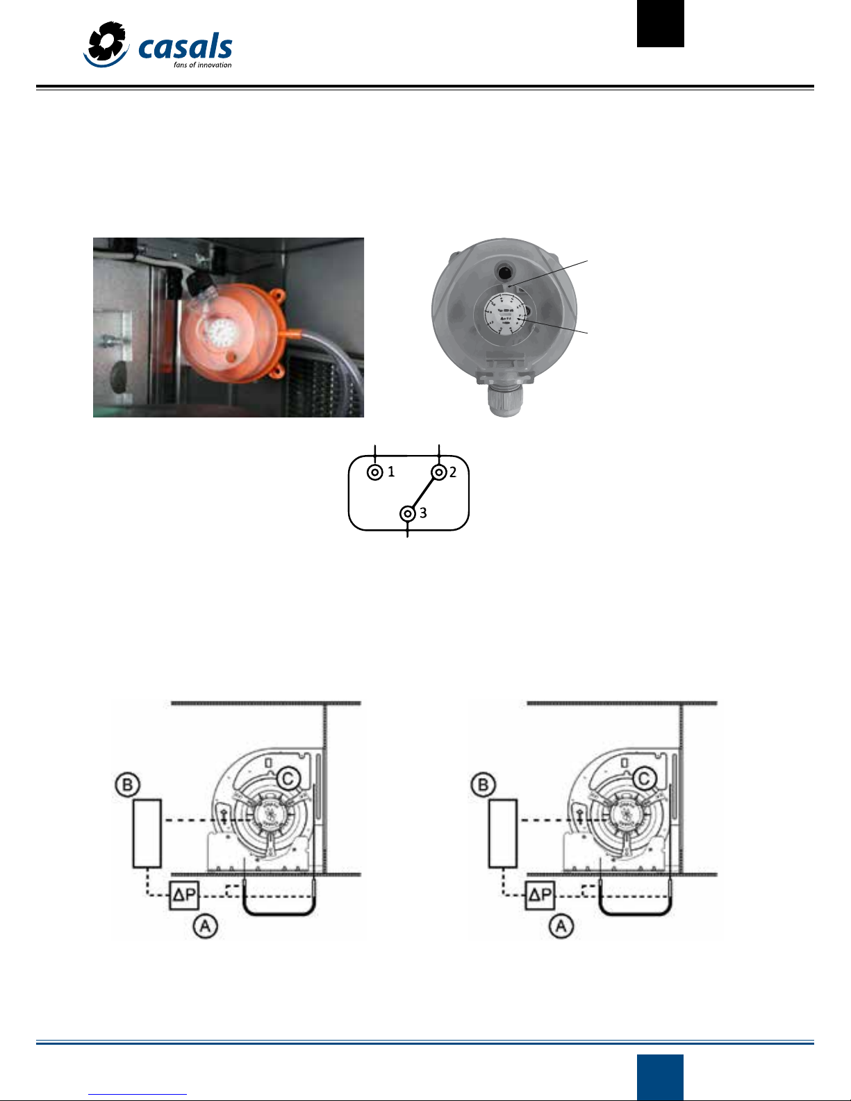
ACCESSORIES - PRESSOSTAT
The differential air pressure switch allows the differential pressure to be monitored between two different points. It is applied to the equipment to collect information about the condition of the filters and also the condition of the fans of the equipment.
The desired pressure differential is set directly on the pressure switch as shown with its electrical connections shown.
Differential regulator
of defined pressure
Regulator of
Pressure diferencial
ACCESSORIES - CONSTANT FLOW
The accessory allows the constant flow to be maintained constant regardless of the variation in pressure drop of the system.
The control of the flow rate is carried out using a relationship between the air flow that moves and the differential pressure as indicated in the images for single-phase fans and three-phase fans.
A - Differential of the pressure sensor.
B - Variator of tension.
C - Fan.
A - Differential of the pressure sensor.
B - Variator of frequency.
C - Fan.
Single phase - CEPHIRUS-2 600/900/1500/2100/3500/4600 Three phase - CEPHIRUS-2 6400/7000

11
CV072018-1
The system uses a differential pressure sensor and a frequency converter (three-phase fans) or a voltage inverter (single-phase fans). The
differential pressure sensor has different operating ranges, and the range of choice depending on the regulation to be performed.
Range of values of
the SPS differential sensor
ACCESSORIES - CONSTANT AIR FLOW
The adjustment of the constant current is made in the frequency converter (three-phase fans) or the voltage converter (single-phase fans)
being, in the case of the frequency converter, a percentage value of the operating range selected in the differential pressure sensor and in
the case of voltage inverter the value of the differential pressure to be maintained.
For variable frequency, the adjustment is made as follows:
access:
MENÚ [FUn-]
SUBMENÚ [PI]
CATEGORY [rPI]
The value of the intended regulation being here imposed.
For the adjustment voltage, variable is performed as follows:
- Press the “A / M” button continuously.
- In the set points menu, set the value of the desired setting (Pa).
12
CV072018-1
Feeding 230 VAC±10%-50Hz
Maximum sensor range (SR)* 0-10000 Pa
Adjustment points (SP mín/SP máx) 10-90% SR
Proportional range ** 5-75% SR
Rules
Low voltage directive 2014/35/EU
EMC directive 2014/30/EU
WEEE directive 2012/19/EU
RoHs directive 2011/65/EU
Simple milling:
Manual mode
Continuous milling:
Installation menu
Adjustment regulator
For the operation an initial adjustment must be made and a flow measurement must be maintained as a function of measurement, the adjustment
value is adjusted.
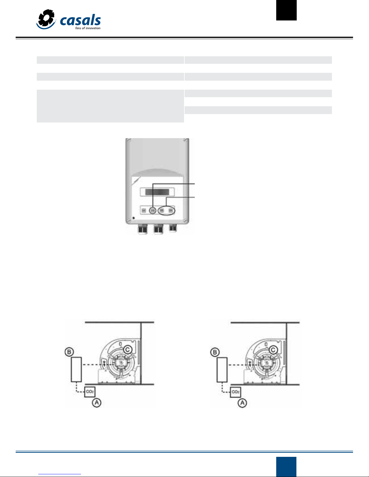
ACCESSORIES - CO
2
CONTROL
Its goal is to monitor the concentration of carbon dioxide in the air in real time and adjust the fan according to the measured value and
the desired concentration of carbon dioxide.
The system uses a carbon dioxide sensor and a frequency converter (three-phase fans) or a voltage inverter (single-phase fans).
A - CO2 sensor.
B - Variable voltage.
C - Fan.
A - CO
2
sensor.
B - Variator of frequency.
C - Fan.
Single phase - CEPHIRUS-2 EEC 600/900/1500/2100/3500/4600 Three phase - CEPHIRUS-2 EEC 6400/7000

13
CV072018-1
The regulation of the CO2 control is carried out in the frequency converter (three-phase fans) or the voltage converter (single-phase fans) being, in
the case of inverter frequency, a percentage value of the reading range of the sensor, and if the inverter of voltage the value of the desired concentration of carbon dioxide (ppm).
For variable frequency, the adjustment is made as follows:
MENÚ [FUn-]
SUBMENU [PI]
CATEGORY [rPI]
The value of the intended regulation being here imposed.
ACCESSORIES - CO2 CONTROL
For the voltage variators the regulation is carried out in the following way:
- Press the “A / M” button continuously.
- In the settings menu, set the value of the desired regulation (ppm).
Feeding 230 VAC±10%-50Hz
Maximum sensor range (SR)* 0-10000 Pa
Adjustment points (SP mín/SP máx) 10-90% SR
Proportional range ** 5-75% SR
Rules
Low voltage directive 2014/35/EU
EMC directive 2014/30/EU
WEEE directive 2012/19/EU
RoHs directive 2011/65/EU
Simple milling:
Manual mode
Continuous milling:
Installation menu
Adjustment regulator

14
CV072018-1
ACCESSORIES - WATER COIL
The heating water coil module uses the flow of hot water to heat the air flow. For correct operation and to avoid damage to the coil, attention
must be paid to the following warnings:
• The coil should only be used for heating.
• Check limits of water temperatures and water pressure.
• All hydraulic connections must be made in accordance with good art practices.
• A trap must be placed in the highest part of the hydraulic circuit.
• A filter must exist in the hydraulic installation.
ACCESSORIES - ELECTRICAL COIL
The electric coil module uses electric heating elements. They are three-phase power supply being presented below the respective connection
diagrams.
For correct operation and to avoid damage to the coil, attention must be paid to the following warnings:
• Make sure that the safety thermostat is installed correctly.
• All connections must be made in accordance with good art practices.
CEPHIRUS-2 600 - 3 kW
CEPHIRUS-2 900 - 12 kW
CEPHIRUS-2 2100 - 12 kW
TP
TP
TP

15
CV072018-1
CEPHIRUS-2 3500 – 18 kW
CEPHIRUS-2 4600/6400 -27 kW
CEPHIRUS-2 7000 - 36 kW
TP- Thermal protection (Safety thermostat)
TP
TP
TP

16
CV072018-1
Note:
Please note that heat recovery units are integrated into a general system. For this reason, failures may be caused by other components of
the system, the incorrect interaction between the unit and the system, or the environmental conditions other than the specificities for the
design of the unit.
Directives: Standard rules:
• Machinery Directive 2006/42 / CE
• EN 60335-1: 2010
• EN 60947-3: 2009
• Low voltage directive 2014/35 / UE
• EN 60947-5-1: 2004 + AC: 2005 + A1: 2009
• EN 13857: 2008
• EMC Directive 2014/30 / UE
• EN 12100-1: 2003
• EN 12100-2: 2003
• ECODESIGN 2009/125 / CE • EN 60204-1: 2006
PROBLEMS POSSIBLE CAUSE CHECK POSSIBLE SOLUTION
High consumption
engine
Different point of performance
of the predicted;
Excess flow;
Check the flow rate and pressure drop;
The fan speed;
Reduce the rotation speed;
Create a pressure drop in the installation;
Excess air flow
System for air distribution, pressure
drop in the overestimated installation;
Check the flow rate and pressure
drop;
The fan speed;
Reduce the rotation speed;
Create a pressure drop in the
installation;
Insufficient air
flow
Air distribution system, the pressure loss of the installation under
estimated;
Check the flow rate and pressure
drop;
The fan speed;
The increase in the speed of rotation
(according to the available power of
the motor and the maximum speed
of the fan);
Excessive noise
Flow too high, very high index, performance;
Pressure drop too high;
Check the flow rate and pressure
drop;
The decrease in the flow velocity;
Avoid unstable fan operation areas;
Damaged bearings, damaged metal
components;
The components in unbalanced
movement;
Bearings of state of the components;
Strange vibrations;
Replace bearings, damaged components;
Replacement of the fan;
The unit does
not work
Could not power source;
Power supply;
Circuit breaker;
Restore the power supply;
The reset of the circuit breaker;
The low efficiency
of the stove
The dirt of the inadequate recovery
element
The state of cleaning stove Clear stove
RESOLUTION OF PROBLEMS

17
CV072018-1
VENTILACIÓN INDUSTRIAL IND S.L.
Crta. Camprodon, s/n
17860 Sant Joan de les Abadesses (Girona)
GPS: N 42º 14’ 10’’, E 2º 17’ 40’’
Tel. (+34) 972720150
Fax (+34) 972721053
E-mail nacional: ventilacion@casals.tv
E-mail export: fans@casals.tv
www.casals.tv
Sr. David Samper
Dir. General
VENTILACIÓN INDUSTRIAL IND S.L.
Crta. Camprodon, s/n
17860 Sant Joan de les Abadesses (Girona)
GPS: N 42º 14’ 10’’, E 2º 17’ 40’’
Tel. (+34) 972720150
Fax (+34) 972721053
E-mail nacional: ventilacion@casals.tv
E-mail export: fans@casals.tv
www.casals.tv
Sr. David Samper
Dir. General
Sant Joan de les Abadesses 02/07/2018
DECLARATION OF CONFORMITY
We hereby declare, under our only responsibility, that the CASALS brand products described in this manual comply with the directives 2014/35/EU (Low Voltage),2006/42/EC (Machinery), 2014/30/EU (Electromagnetic compatibility), 2009/125/EC* (Ecodesign) and
with all the standards mentioned in this instruction manual.
*The compliance of this Directive only affects to ErP marked compliant models.
 Loading...