

Casall 91022 User Manual
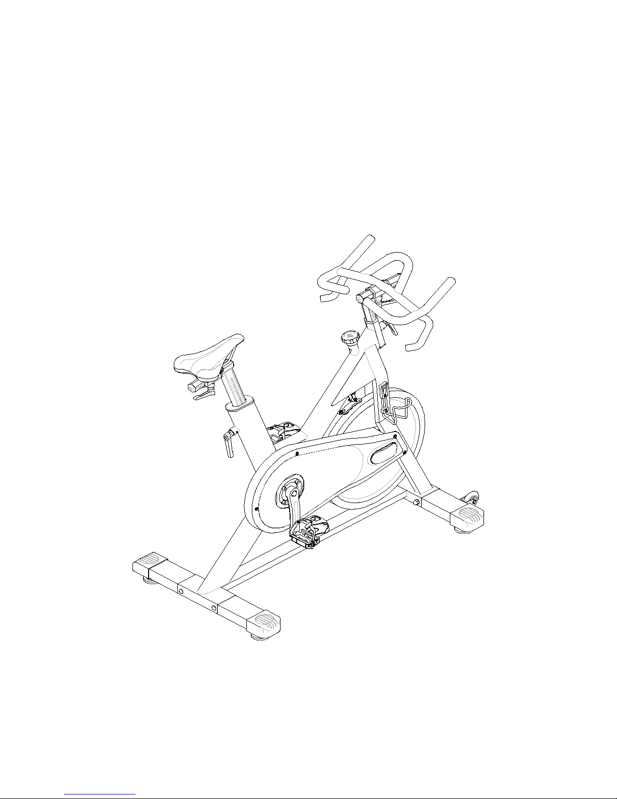
INDOOR BIKE
91022
MANUAL

91022 INSTRUCTIONS FOR USE
1) The model 91022 is designed to be used as light commercial use or
home use. It has a fixed wheel driven flywheel and should be used
under professional supervision. or asking your supplier before using.
2) Installation – it is important that the 91022 is correctly assembled and we recommend
that installation and assembly be carried out by suitably qualified personnel.
3) Handlebar and seat adjustment. It is important that the handlebar and seat are
set at the correct height for your body. Ask your instructor for assistance.
Adjusting the handlebar height - Make sure it is securely tightened and that there
is no lateral or vertical movement of the handlebar. Undo the Quick Release knob
which is located in front of head tube. Slide the handlebar/stem up or down to the
required height and then retighten.
The handlebar/stem position can also be adjusted forwards or backwards. Undo
the Quick Release lever located on below the slider. Slide the handlebar/stem
assembly forwards or backwards until you reach the required position. Then
securely re-tighten the Quick Release lever.
Adjusting the seat height – refer to above mention.
NOTE: there is a safety line engraved on the seat post. On no account
should the seat post ever be raised above this line.
4) Pedals and toestraps – your feet should be securely positioned in the toe clips
during the exercise. Put your foot as far forward as you can into the toe-clip and then pull the strap tight.
5) Resistance system- 91022 indoor bike is with durable belt direct drive transmission system,
to adjust the exercising resistance on the completed indoor bike, undo the simply loosen or tighten
using adjustment knob. Press down the brake lever for stopping the wheel.
6) The 91022 should operate on a level surface with no lateral movement.
There are height adjuster pads located on either side underneath the rear foot.
Turn these pads clockwise or anti-clockwise until the bike is totally stable on the ground.
7) Maintenance – like any other mechanical cycling device, the 91022 should be
regularly maintained. Ask your supplier for a detailed maintenance programme.
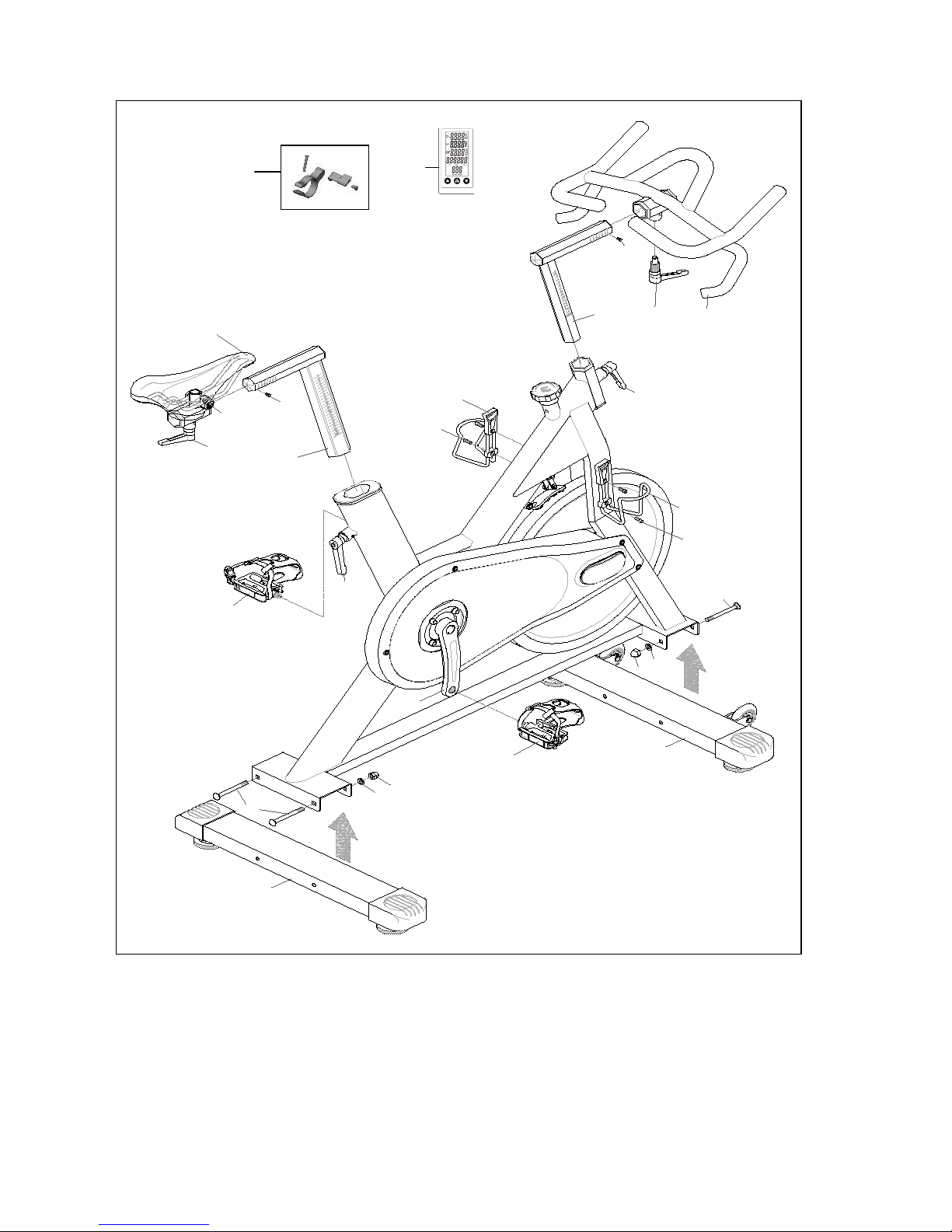
91022 Assembly Diagrams
81
82
1 7
1 8
1 2
2 0
1 5
7 L
3
2
1 8
2 0
1 4
9
1 0
7 0 R
7 R
5
4
1 8
5
1 8
1 1
9
1 0
3
4
6
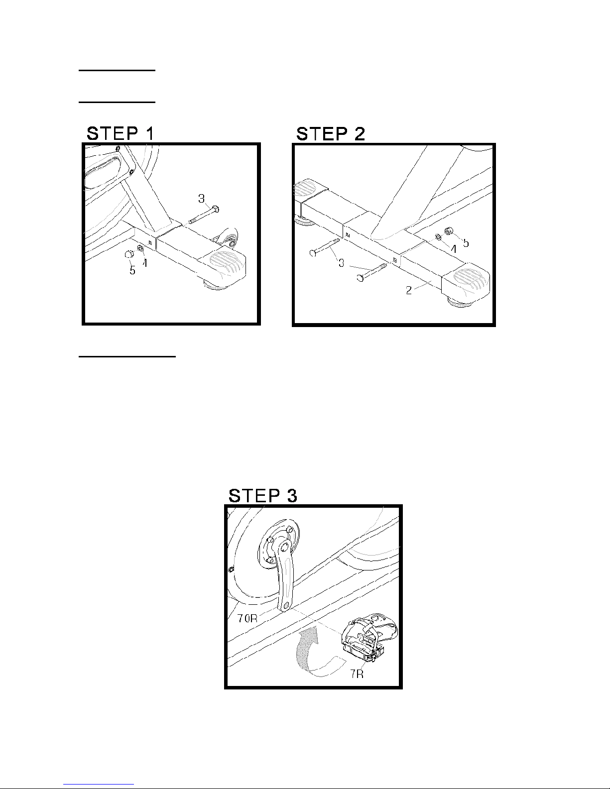
91022 ASSEMBLY
Step 1 (foot)
Attach the front foot (6) to the frame using the bolt (3), washer (4) and nut (5).
Step 2 (foot)
Attach the rear foot (2) to the frame using the bolt (3), washer (4) and nut (5).
Step 3. (pedals)
attach the pedals (7R/7L) into the crank arms (70R/70L), each pedal
is marked with the letter R(right) or R(right) to denote the side of the bike
they are on. NOTE: the right hand crank is on the same side as the
chain cover (61). Be careful to align the threads correctly to avoid any damage.
A little grease on the thread should help the pedals to screw in easily
and correctly, tighten using a 15mm spanner, both pedals threads should
tighten towards the front of the bike.
 Loading...