

Casablanca Fan Company 84GxxD User Manual

CONTENTS
INTRODUCTION . . . . . . . . . . . . . . . . . . . . . . . . . . . . . . . . . . . . . . . . . . . . . . . . . . . . . . . . . . . . . . . . . . . . . . 1
MOUNTING RECOMMENDATIONS . . . . . . . . . . . . . . . . . . . . . . . . . . . . . . . . . . . . . . . . . . . . . . . . . . . . . . . . . . 2
PREPARATION INSTRUCTIONS . . . . . . . . . . . . . . . . . . . . . . . . . . . . . . . . . . . . . . . . . . . . . . . . . . . . . . . . . . . 3
FAN INSTALLATION (USA) . . . . . . . . . . . . . . . . . . . . . . . . . . . . . . . . . . . . . . . . . . . . . . . . . . . . . . . . . . . . . . . 4
FAN INSTALLATION (OUTSIDE USA) . . . . . . . . . . . . . . . . . . . . . . . . . . . . . . . . . . . . . . . . . . . . . . . . . . . . . . . . 10
CONTROL FEATURES:
3-SPEED CONTROL WIRING . . . . . . . . . . . . . . . . . . . . . . . . . . . . . . . . . . . . . . . . . . . . . . . . . . . . . . . . . . . 14
3-SPEED OPERATIONS . . . . . . . . . . . . . . . . . . . . . . . . . . . . . . . . . . . . . . . . . . . . . . . . . . . . . . . . . . . . . . . 15
TROUBLESHOOTING . . . . . . . . . . . . . . . . . . . . . . . . . . . . . . . . . . . . . . . . . . . . . . . . . . . . . . . . . . . . . . . . . . . 16
READ AND SAVE THESE INSTRUCTIONS
SAFETY FIRST
Safety and the proper operation of your Casablanca fan both require a thorough knowledge of the product
and proper installation; therefore, before attempting to install and operate your Casablanca fan, read this
owner’s manual completely and carefully. Retain this manual for future reference.
CAUTION: To avoid possible electrical shock, make certain that electricity is turned o ff at
the circuit breaker or fuse box before attempting any installation procedure.
BEFORE YOU START
• All wiring must be in accordance with the National Electric Code ANSI/NFPA 70-1993 and the appropriate local electrical
codes. The National Electric Code requires proper grounding as a precaution against electrical shock. A qualified electrician should be consulted if you are unsure.
• This fan is designed to be installed on an existing electrical outlet box. The outlet box must be UL Listed for ceiling fan
installations, if it is not, a new box must be installed. Casablanca extension poles are available for sloped or high ceiling
installations.
• This ceiling fan requires a grounded electrical supply of 120 VAC, 60 Hz and a minimum 15 amp circuit. The maximum
current requirement for the fan with light fixture is 3.8 amps. The fan uses about 1 amp or 100 watts. Maximum light
current is 2.8 amps or 340 watts of lighting.
• Where wire nuts are employed, be sure all bare wires are within the connectors. When installing the canopy hatch, make
sure all wires are within the canopy and that no wires are being pinched.
For best performance and for your warranty to be valid,
use only genuine Casablanca blades, light fixtures, and accessories.
• The blades in each pack are matched for equal
weight to assure smooth fan operation. If
more than one fan is being installed, be
careful not to mix blades from different
cartons.
• Inspect the contents of your carton for
possible shipping or handling damage and
report any such damage directly to your
authorized Casablanca dealer.
• It is always a good idea to have an assistant
to help with the installation.
• When cleaning, painting, or working near
your fan, be very careful of the fan and blades.
Always turn the power OFF to the ceiling fan
before servicing it, working on it, or replacing
light bulbs.
• Never insert anything into the path of the
fan blades while the fan is in operation.
• Never install a fan over a pool or spa.
• Never operate a fan that has been damaged
in any way. Contact Casablanca Fan Company
by calling toll free 1-888-227-2178, or
contact your local authorized Casablanca
dealer for assistance in obtaining service.
PN 8443011 AT1008
SAFE USE
FUSE BOX
(REMOVE FUSE FOR THE
CIRCUIT YOU WILL BE
WORKING ON)
CIRCUIT BREAKER
(TRIP BREAKER FOR THE
CIRCUIT YOU WILL BE
WORKING ON)
18"
70"
84"
1
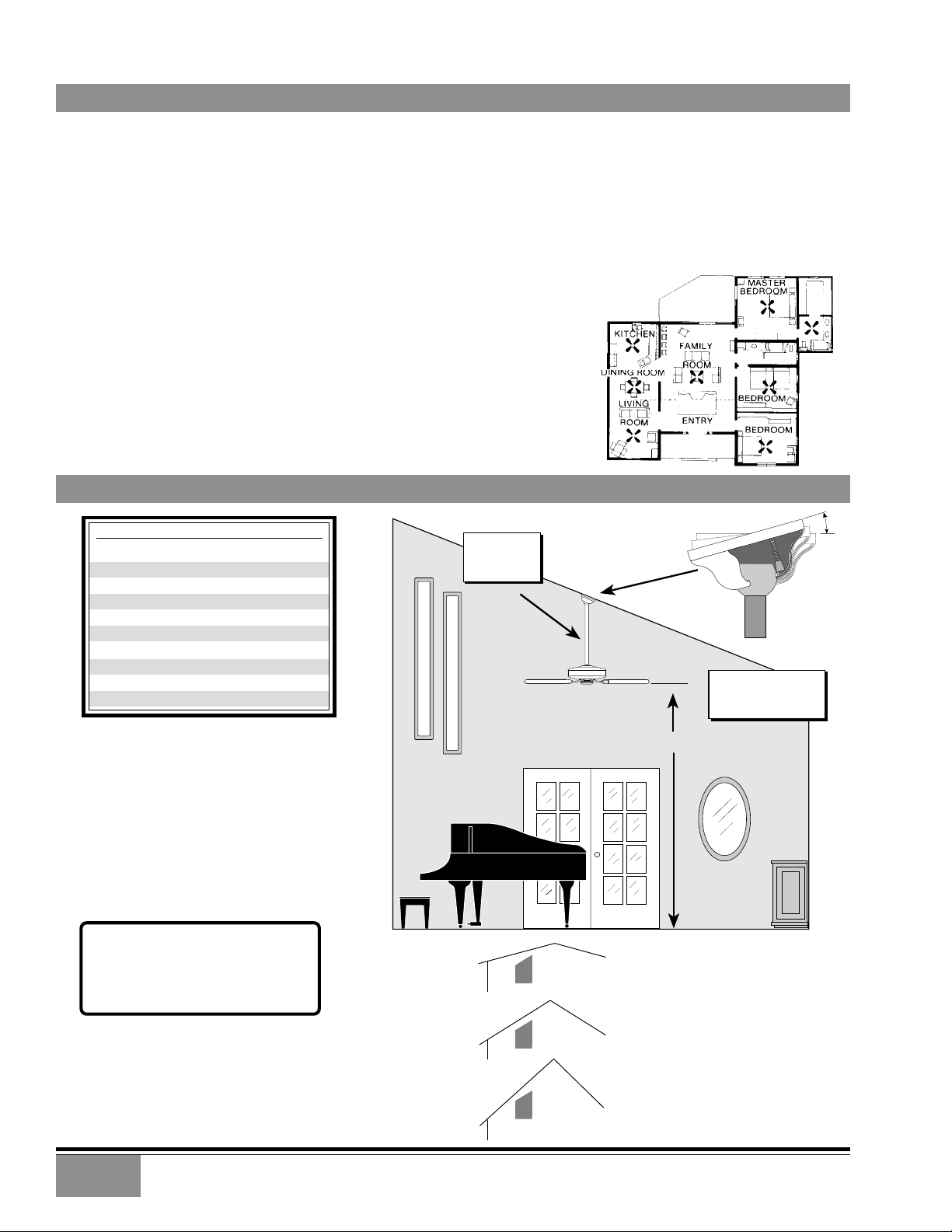
MOUNTING RECOMMENDATIONS
Before mounting your Casablanca fan, read the following helpful recommendations. The location of the fan, air circulation,
and fan size are all important factors to consider before installation.
Location
Ceiling fans have practical uses in almost every room in your home. We suggest you follow these mounting
recommendations as you decide where to install your Casablanca fan.
• For safety reasons, the fan blades must be a minimum of 7' above the floor.
• Do not locate the fan in a doorway or above a swinging door.
• In any installation, the tips of the blades must be at least 18" from the wall in order to
provide sufficient clearance for the blades.
• In bedrooms, fans work best when mounted above the foot of the bed.
• Over pool tables, be sure to provide plenty of clearance to avoid damage from
pool cues.
• In low ceiling locations, our optional Low Ceiling Adaptor (LCA)—available at
extra cost—can be used to gain 31⁄2".
• In kitchens be sure to allow for open cupboard doors to clear the fan blades.
• Do not install a fan close to, or over, a pool or spa. High humidity combined
with corrosive gases will destroy the finish and warp the blades.
Fan Size
Variable fan speed capability permits the use of a full-size 52" fan even in
smaller rooms. For very large rooms, two fans may be needed.
SLOPED CEILING INSTALLATIONS
MAXIMUM
Suggested Extension Pole Lengths
Ceiling Height
8'
8' 6"
9'
9' 6"
10'
11'
12'
13'
14'
Pole Length
Standard
Standard
6"
12"
12"
18"
24"
36"
48"
EXTENSION
POLE
HANG-TRU®
ANGLE 32º
BLADES MUST BE A
MINIMUM OF 7′
ABOVE THE FLOOR
32°
When to Use Extension Poles
For best performance and best appearance,
an extension pole should be used with
your Casablanca fan when installing on
high (cathedral) ceilings or sloped
ceilings. Casablanca offers standard poles
in increments of 6" up to 5'. Custom poles
are available in lengths up to 10'. See your
Authorized Casablanca Dealer for details.
Note: Fan may wobble or vibrate if
pole length is not long enough and
inside blade is too close to downslope
or side wall. Extending pole length
will usually solve problem.
Calculation of 32°
Use the tear-off Ceiling Angle Template card inserted in the
back of this manual, it provides you with a simple ‘go’ or
‘no-go’ for installing your fan on a sloped ceiling.
2
7′ MINIMUM
EXAMPLE 1
This slope is less than 32˚.
It is OK to install your fan.
EXAMPLE 2
This slope is 32˚. This is the maximum
slope that will allow the fan to hang
straight down. It is OK to install your
fan.
EXAMPLE 3
This slope is more than 32˚.
Your fan will not hang straight down, an
adaptor is necessary. Contact your local
Authorized Casablanca Dealer in regards
to purchasing a “Slope Ceiling Adaptor.”

FOUR SEASONS™ III
PREPARATION INSTRUCTIONS
Unpacking: Before assembling and installing your ceiling fan, remove all parts from the shipping cartons and check them
against the parts listed here. Before discarding packaging material, be certain that all parts have been removed.
GETTING STARTED
Carton Contents
The fan carton contains the fan body, warranty card, owner's
manual, and all the parts necessary to assemble and install
your Casablanca ceiling fan. These parts are shown at the
start of each installation section. Before you start, go through
this Owner’s Manual and confirm that you have all the parts
shown in each section.
PERMA•LOCK™ HARDWARE
Be sure to use only genuine Casablanca blades. The blade
shrink wrap holds 5 blades of matched weight. If more than
one fan is being installed, be sure not to mix blade sets.
CAUTION: When removing the shrink wrap,
be careful not to scratch the blades.
ALLEN SET SCREW
1
4-20 x 1 4"
(PRE-INSTALLED)
3mm
ALLEN WRENCH
FAN PREPARATION
IMPORTANT SAFETY INFORMATION!
BEFORE STARTING THE INSTALLATION OF YOUR CEILING FAN, INSTALL THE
THREADED DOWNROD INTO THE MOTOR COUPLING AND LOCK THE ASSEMBLY
Prepare for fan installation as follows:
Step A. Route the wires from the motor through the
Perma•Lock™ downrod and ball assembly.
Tip: The downrod has a tapered thread
that is designed to lock completely when
correctly installed.
Step B. Using the provided allen wrench, loosen the set screw
several turns to allow installation of the downrod. Thread
the downrod into the motor coupling until it stops turning,
this will take at least four and a half full turns.
Step C. Securely tighten the set screw with the provided allen
wrench to ensure safe operation of your fan.
CAUTION: Failure to fully lock in the downrod before securely tightening the allen set
screw may cause the fan to separate from
the downrod during normal operation!
DOWNROD & BALL
ASSEMBLY
MOTOR
WIRES
GROUND
WIRE
DOWNROD
& BALL
ASSEMBLY
TAPERED
THREAD
ALLEN
SET SCREW
MOTOR
COUPLING
GETTING STARTED
Installing a New Ceiling Fixture Outlet Box
If you do not have an existing fixture located where you wish
to place your Casablanca fan, an approved ceiling fixture
outlet box must be installed and wired.
WARNING: To reduce the risk of fire, electrical shock,
or personal injury, mount to outlet box marked
acceptable for ceiling fan support using the
mounting hardware provided with the outlet box.
Using Existing Ceiling Fixture Outlet Box
After turning the power OFF at its source (either circuit breaker
or fuse box), lower the old fixture and disconnect the wiring.
Check the ceiling fixture outlet box to be sure that it is
marked ‘Approved for ceiling fan mounting’. If it is not, a new
box must be installed.
NOTE: The fan weight is 17 pounds.
3
FOUR SEASONS™ III
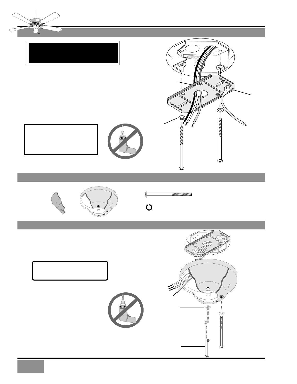
CROSSBAR MOUNTING BRACKET INSTALLATION
FOR FAN INSTALLATION OUTSIDE THE
USA GO TO PAGE 8
EXCLUDING MODELS ENDING IN ‘E’
Proceed with installation as follows:
Step 1. Route the wires from the ceiling outlet box through
the crossbar mounting bracket center hole. Attach the bracket,
with ground wire and ridges down, to the ceiling fixture outlet
box with the mounting hardware included with the outlet
box.
Tighten the screws firmly by hand only, being careful not to
bend the bracket by over tightening.
CEILING FAN
APPROVED
WIRING BOX
CROSSBAR
MOUNTING
BRACKET
CEILING
WIRING
RIDGE
SIDE
DOWN
CAUTION: To reduce the risk of
personal injury, use only the
mounting hardware provided with
the approved outlet box to install
the crossbar mounting bracket.
CANOPY HARDWARE
CANOPY
HATCH
CANOPY
CANOPY INSTALLATION
Step 2. Attach the canopy to the crossbar
mounting bracket with three of the 8-32 x 21/4"
long canopy screws and canopy lock washers.
Tighten the screw firmly by hand only.
NOTE: On sloped ceilings, align the
canopy opening towards the top or
room peak.
FLAT
WASHER
APPROVED
OUTLET
BOX
HARDWARE
CANOPY SCREW (4)
CANOPY LOCK WASHER (4)
CANOPY
GREEN
GROUND
WIRE
CROSSBAR
MOUNTING
BRACKET
4
CANOPY LOCK
WASHER
CANOPY
SCREW


FOUR SEASONS™ III
CROSSBAR MOUNTING BRACKET INSTALLATION
Step 7. To hang the fan body in the canopy,
hold the fan body firmly and insert the ball
into the canopy opening. Check that no wires
were pinched. Rotate the fan body until the
slot in the nylon ball fits into the pin opposite
the canopy opening.
NOTE: The fan weight is 17 pounds.
NOTE: Independent control of the
light fixture using a W-8 requires an
additional power wire run from the
wall switch to the fan. See Page 12
for wiring.
HANGING THE FAN
D1
OPTION
WIRE
CANOPY ELECTRICAL CONNECTIONS
Step 8a. Attach the fan wires to the ceiling fixture outlet
box wiring by twisting the bare ends of the wires together
and then securing with a wire nut. Test that the connection
is secure by pulling on the wire nut. Connect in this order:
Step 8b. Pull Chain or W-4 Wiring Connections
• GREEN leads from mounting plate and fan to GROUND
conductor of power source. Secure with wire nut.
• WHITE wire from fan to white NEUTRAL wire in ceiling fixture
outlet box. Secure with wire nut.
• BLUE wire and BLACK power wire from fan to BLACK power
wire in ceiling outlet box. Secure with wire nut.
Step 8c. W-8 Wiring Connections
• GREEN leads from mounting plate and fan to GROUND
conductor of power source. Secure with wire nut.
• WHITE wire from fan to white NEUTRAL wire in ceiling
fixture outlet box. Secure with wire nut.
• BLACK power wire from fan to RED wire from W-8 in ceiling
outlet box. Secure with wire nut.
• BLUE wire from fan to YELLOW wire from W-8 in ceiling
outlet box. Secure with wire nut.
BALL
SLOT
CAPPED BLUE D1-OPTION WIRE ON 3-SPEED ONLY
FOR INDEPENDENT W-8 LIGHT CONTROL
WIRE NUT
PULL CHAIN OR
W-4 CONNECTIONS
2 BLACK & BLUE
D1-OPTION WIRES
(WITHOUT W-8)
2 WHITE WIRES
3 GREEN WIRES
W-8 CONNECTIONS
BLUE & YELLOW
WIRES
BLACK & RED
WIRES
2 WHITE WIRES
PIN
NOTE: SEE PAGE 12 FOR ADDITIONAL WIRING INFORMATION.
CANOPY HATCH INSTALLATION
Step 9. Tuck the wires into the canopy
with the wire nuts pointed upwards, so
that the WHITE and BLACK wires are on
opposite sides of the canopy and all wires
are clear of the canopy opening.
Step 10. Install canopy hatch with the
last canopy screw and lock washer. To do
this, tilt the fan body away from the hatch
opening.
Tighten the screws firmly by hand only.
Step 11. Straighten the fan, then check
to ensure that there is no movement
between the canopy and ceiling or HangTru ball and top support shaft.
CANOPY
HATCH
LOCK
WASHER
CANOPY
SCREW
6
3 GREEN WIRES
TILT THE
FAN TO
INSTALL
LAST
CANOPY
SCREW
 Loading...