

NOUVELLE
OWNERS MANUAL
CONTENTS
INTRODUCTION ..........................................................................................................................................1
MOUNTING RECOMMENDATIONS ..................................................................................................................2
FAN INSTALLATION - GETTING STARTED ......................................................................................................3
ADAPTOR PLATE INSTALLATION...................................................................................................................4
FAN PREPARATION .....................................................................................................................................5
INSTALLATION & WIRING............................................................................................................................6
LIGHT FIXTURE INSTALLATION ...................................................................................................................9
NO LIGHT FIXTURE OPTION.......................................................................................................................10
INTELI•TOUCH CONTROL OPERATION.........................................................................................................12
TROUBLESHOOTING ..................................................................................................................................15
READ AND SAVE THESE INSTRUCTIONS
SAFETY FIRST
Safety and the proper operation of your Casablanca fan both require a thorough knowledge of the
product and proper installation; therefore, before attempting to install and operate your Casablanca
fan, read this owner’s manual completely and carefully. Retain this manual for future reference.
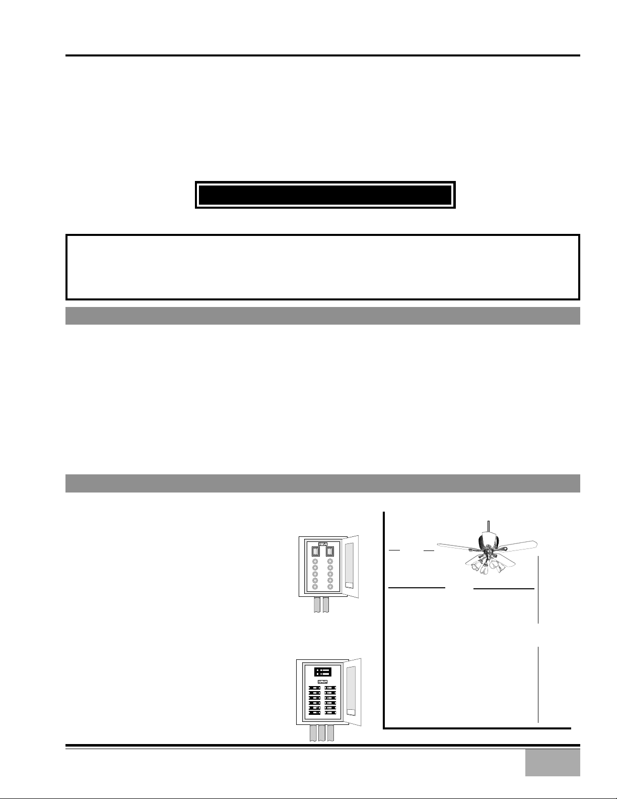
CAUTION: T o av oid possible electrical shock, make certain that electricity is turned o ff
at the circuit breaker or fuse box before attempting any installation procedure.
BEFORE YOU START
• All wiring must be in accord ance with th e Nati onal Electri c Code ANSI/NFPA 70-1993 and the appropriate local electrical
codes. The N ati on al Electri c Cod e requir es proper groundin g as a precauti on again st electri cal sh ock. A qu alifi ed electrician should be consulted if you are unsure.
• This fan is design ed to be in stalled on an e xisting electri cal outlet bo x. Th e outlet box m ust be UL Listed f or ceilin g f an
installations , if it is not, a n ew box must be in stalled. Casablan ca extensi on poles are available f or sloped or high ceilin g
installations.
• This ceiling fan requires a grounded electrical supply of 120 VAC, 60 Hz and a minimum 15 amp circuit. The maximum
current requirement for the fan with light fixture is 3.8 amps. The fan uses about 1 amp or 100 watts. Maximum light
current is 2.8 amps or 340 watts of lighting.
• Where wire n uts are employed , be sur e all bare wir es are within th e conn ectors. Wh en in stalling th e canopy hatch, m ak e
sure all wires are within the canopy and that no wires are being pinched.
For best performance and for your warranty to be valid,
use only genuine Casablanca blades, light fixtures, and accessories.
• The blades in each pack are m atched for equal
weight to assure smooth fan operation. If
more than one f an is being installed, be car eful not to mix blades from differ ent carton s .
• Inspect the conten ts o f your carton for possible shipping or handling d amage and report
any such dam age directly to your auth orized
Casablanca dealer.
• It is always a good id ea to have an assistant
to help with the installation.
• When cleaning, painting, or working near
your fan, be very careful of th e fan and blades.
Always turn the power OFF to the ceiling f an
before servicing it or working on it.
• Never insert anything into the path of the
fan blades while the fan is in operation.
• Never install a fan over a pool or spa.
• Never operate a fan that has been damaged
in any way . Contact Casablanca Fan Compan y
by calling 1-888-227-2178, or contact your
local authorized Casablanca dealer f or assistance in obtaining service.
P/N 9643010 REV. B P/D FEB00PDG
SAFE USE
FUSE BOX
(REMOVE FUSE FOR THE
CIRCUIT YOU WILL BE
WORKING ON)
CIRCUIT BREAKER
(TRIP BREAKER FOR THE
CIRCUIT YOU WILL BE
WORKING ON)
18″
74″
84″
1
MOUNTING RECOMMENDATIONS
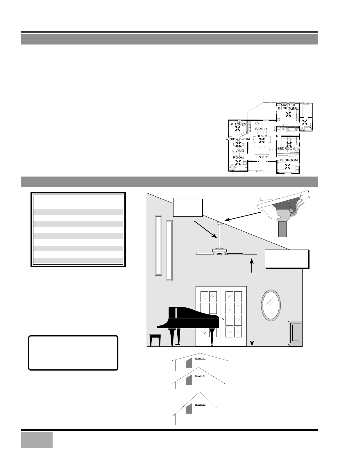
Before moun ting your Casablan ca f an, read th e following helpful recommendation s . The locati on o f the f an, air cir culation,
and fan size are all important factors to consider before installation.
Location
Ceiling fans have pr actical uses in alm ost every r oom in your h om e . W e sugg est you f ollow th ese m ounting recommendations as you decide where to install your Casablanca fan.
• For safety reasons, the fan blades must be a minimum of 7′ above the floor.
• Do not locate the fan in a doorway or above a swinging door.
• In any installation, the tips of the blades must be at least 18″ from the wall in order to
provide sufficient clearance for the blades.
• In bedrooms, fans work best when mounted above the foot of the bed.
• Over pool tables, be sure to provide plenty of clearance to avoid damage from
pool cues.
• In kitchens be sure to allow for open cupboard doors to clear the fan blades.
• Do not install a fan close to, or over, a pool or spa. High humidity combined
with corrosive gases will destroy the finish and warp the blades.
Fan Size
Variable f an speed capability permits the use o f a full-size 52″ f an even in
smaller rooms. For very large rooms, two fans may be needed.
SLOPED CEILING INSTALLATIONS
Suggested Extension Pole Lengths
Ceiling Height
8′
8′ 6″
9′
9′ 6″
10′
11′
12′
13′
14′
Pole Length
Standard
Standard
6″
12″
12″
18″
24″
36″
48″
EXTENSION
POLE
MAXIMUM
HANG-TRU®
ANGLE 32º
BLADES MUST BE A
MINIMUM OF 7′
ABOVE THE FLOOR
32°
When to Use Extension Poles
For best performance and best appear ance,
an extension pole should be used with
your Casablanca fan when installing on
high (cathedral) ceilings or sloped ceilings. Casablanca offers standard poles in
increments of 6″ up to 5′. Custom poles
are available in lengths up to 10′. See your
Authorized Casablanca Dealer f or details.
Note: Fan may wobble or vibrate if
pole length is not long enough and
inside blade is too close to downslope
or side wall. Extending pole length
will usually solve problem.
Calculation of 32°
Use the tear-off Ceiling Angle Template card inserted in the
back of this manual, it provides you with a simple ‘go’ or
‘no-go’ for installing your fan on a sloped ceiling.
2
7′ MINIMUM
EXAMPLE 1
This slope is less than 32˚.
It is OK to install your fan.
EXAMPLE 2
This slope is 32˚. This is the maximum
slope that will allow the fan to hang
straight down. It is OK to install your
fan.
EXAMPLE 3
This slope is more than 32˚.
Your fan will n ot han g str ai ght d own, an
adaptor is necessary. Contact your local
Authorized Casablanca Dealer in regards
to purchasing a “Slope Ceiling Adaptor.”
™
NOUVELLE
INSTALLATION INSTRUCTIONS
Unpacking: Before assembling and installing y our ceiling fan, remo ve all parts from the shipping
cartons and check them against the parts listed in instructions.
Before discarding packaging material, be certain that all parts have been removed.
GETTING STARTED
Carton Contents
The fan carton contains the fan body, warranty card, owner's
manual, an d all the parts necessary (except blad es) to assemble
and install your Casablanca ceiling fan. These parts are shown
at the start of each installation section. Before you start, go
through this Owner’s Man ual an d confirm that you have all th e
parts shown in each section.
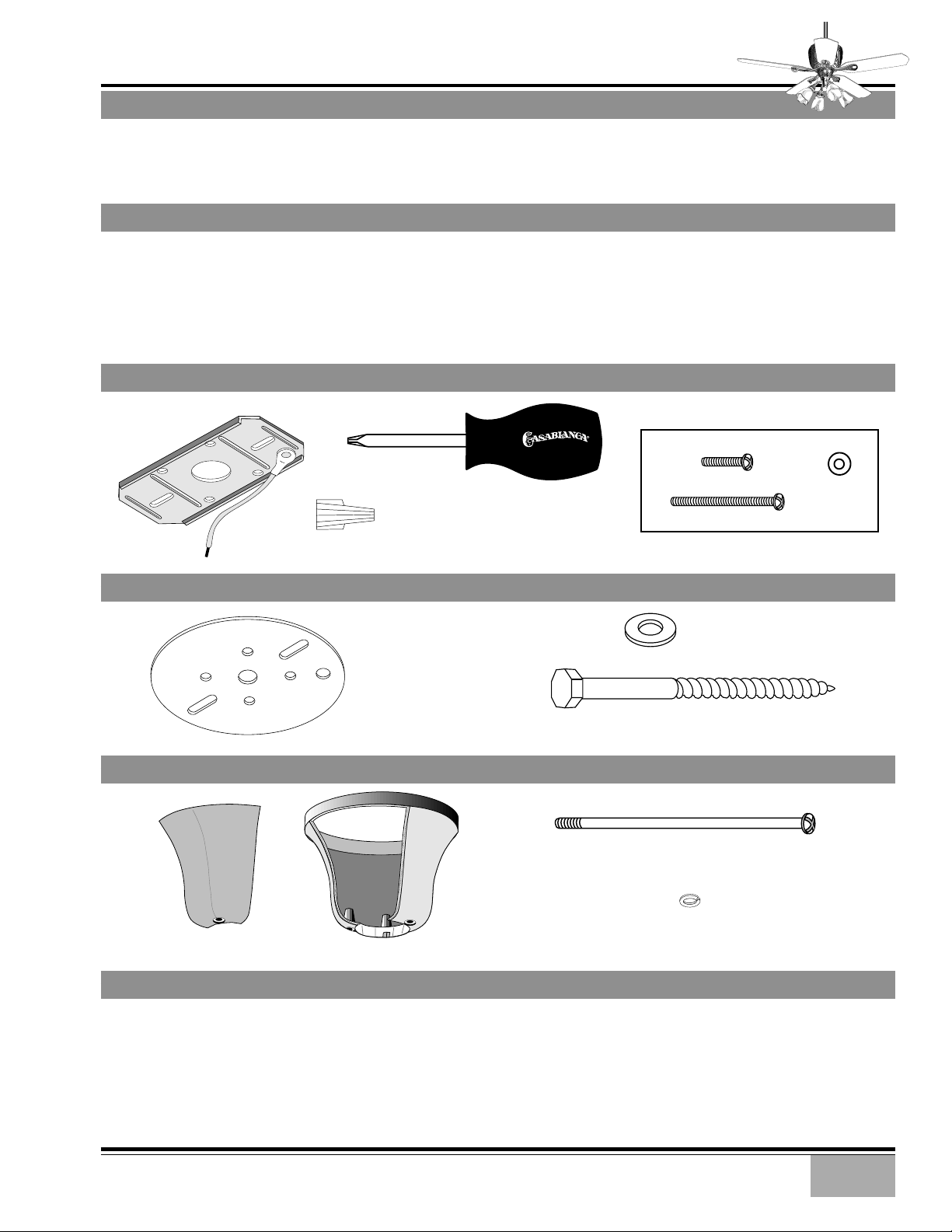
CEILING HARDWARE
CROSSBAR
MOUNTING
BRACKET
Be sure to use only genuine Casablanca blades. The blade
shrink wrap holds 5 blades of matched weight. If more than
one fan is being installed, be sure not to mix blade sets.
CAUTION: When removing the shrink wr ap, be careful not
to scratch the blades.
R
ADDITIONAL HARDWARE
CANOPY
HATCH
PHILLIPS
SCREWDRIVER
WIRE NUT (4)
SUPPORT INSTALLATION PARTS
CANOPY
ADAPTOR
PLATE
CANOPY HARDWARE
CANOPY
SCREW 1″(2)
SCREW 2
CANOPY SCREW
8-32 X 4
CANOPY LOCK WASHER
1
/4″ (2)
LARGE
FLAT WASHER
3
LAG SCREW
3
/8” #7 X 5” (1)
1
/8”(4)
#8 (4)
/8” (1)
FLAT
WASHER
(2)
GETTING STARTED - CONTINUED
Installing a New Ceiling Fixture Outlet Box
If you do not have an existin g fixture located where you wish
to place your Casablanca fan, an approved ceiling fixture
outlet box must be installed and wired.
Warning: To reduce the risk of fire, electrical shock, or
personal injury, mount to outlet box marked acceptable for ceiling fan support.
Using Existing Ceiling Fixture Outlet Box
After turning the power OFF at its source (eith er circuit breaker
or fuse box), lower the old fixture an d disconnect the wirin g.
Check the ceiling fixtur e outlet box to be sur e that it is a UL
listed ceiling box for ceiling fan applications. If it is not, a
new box must be installed.
3
NOUVELLE
ADAPTOR PLATE INSTALLATION
™
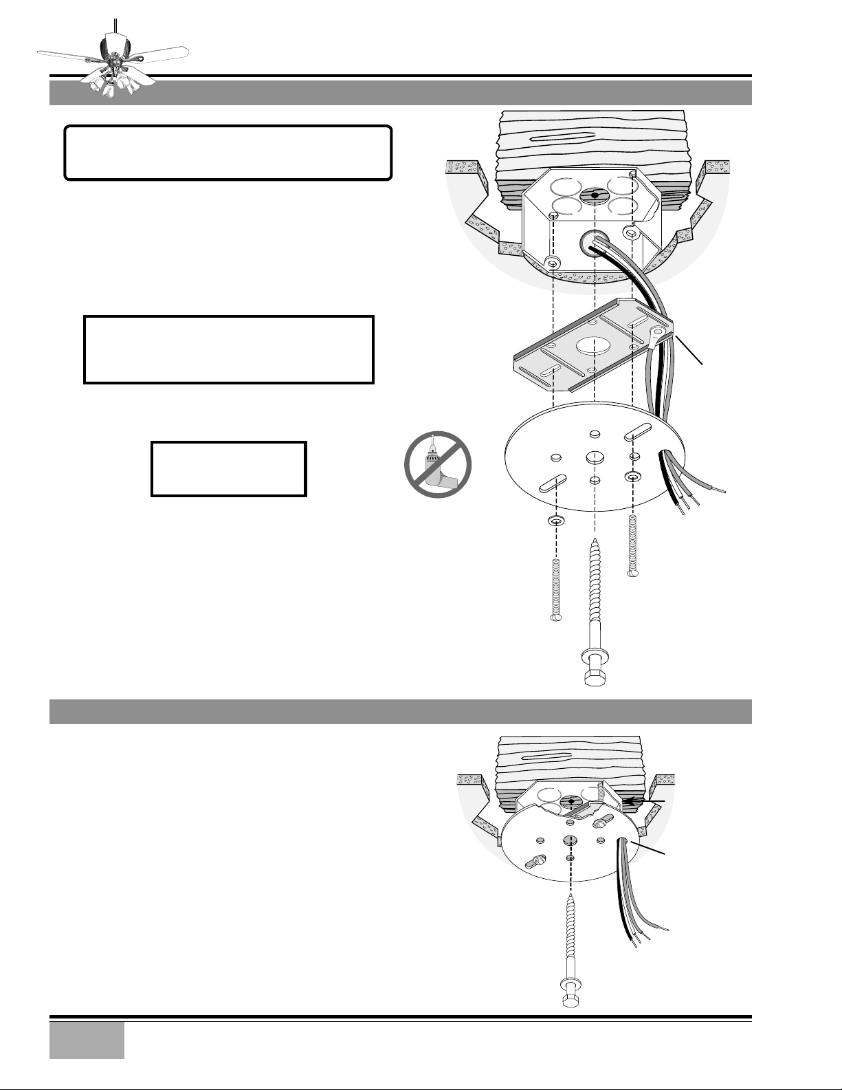
Note: After removing the old fixture, check the outlet box
to insure that it is supported by a joist or beam across its
upper surface. If not, a 2" x 4" stud must be installed.
Proceed with installation as follow s:
Step 1. Remove the knock out plug in the cen ter o f the outlet
box or drill a
drill a
1
1
/2″ hole for the lag scr ew to pass through. Th en
/4″ guide hole in to th e joist or beam to a depth of 3″.
CAUTION: To reduce the risk of personal injury,
use only the mounting hardware provided with
the approved outlet box to install the crossbar
mounting bracket.
WARNING!
SUPPORT DIRECTLY TO
BUILDING STRUCTURE.
JOIST
CEILING FAN
APPROVED
WIRING BOX
CROSSBAR
MOUNTING
BRACKET
WASHER
FLAT
CEILING
WIRING
RIDGE
SIDE
DOWN
GREEN
GROUND
WIRE
LAG SCREW INSTALLATION
Step 2. Route the outlet box wires through the
eter outer hole of the canopy adaptor plate. Attach the
crossbar and canopy ad aptor plate to outlet box with screws
provided.
Step 3. With the large wash er attach ed , pass th e lag scr ew
through the center h ole o f canopy adaptor plate and scr ew
into guide h ole. Tighten until outlet box is firmly mounted
to beam. This box must be firmly secured to th e ceiling. W e
recommend that the ceiling fixture outlet box be of sufficient capacity enablin g it to support th e wei gh t o f f an an d
light fixture under any conditions.
1
/2″ diam-
APPROVED
OUTLET BOX
HARDWARE
LAG
SCREW
LARGE
WASHER
1
/2″ DIAMETER
OUTER HOLE
4
NOUVELLE
CANOPY INSTALLATION
™
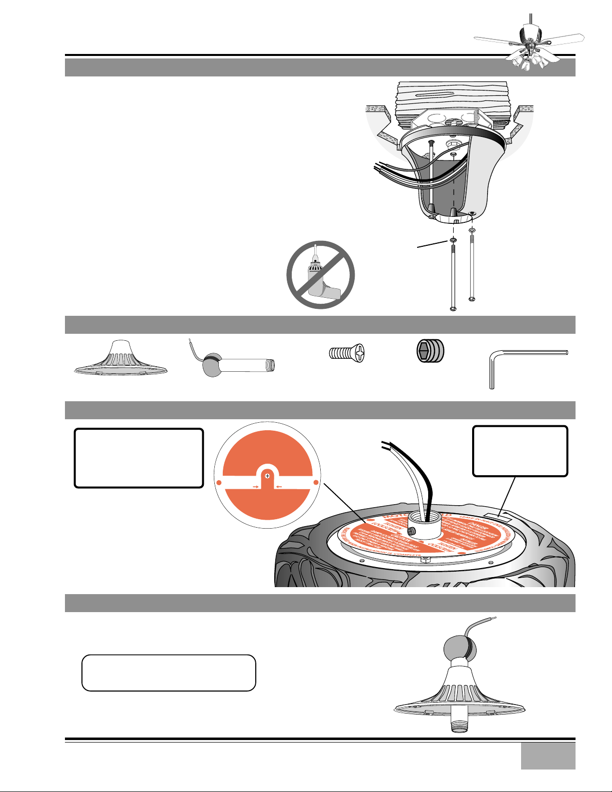
Step 4. Attach the canopy to th e cross bar with
three (3) of the 8-32 X 4
1
/8″ canopy screws and
#8 lock washers, hand tigh ten until snug against
the ceiling. On sloped ceilings , align the canopy
hatch opening toward the top or peak of the
room. Your Casablanca fan may be installed on
a vaulted or cathedral ceilin g in the sam e manner as described for a flat ceiling.
The Hang-Tru
®
mounting system makes it possible to hang your fan on ceilings sloped up to
a 32° angle.
FAN PREPARATION - HARDWARE
MOTOR COVER
DOWNROD &
BALL ASSEMBLY
CANOPY
HATCH
OPENING
PHILLIPS
COUNTERSUNK SCREW
8-32 X
9
/16″
CANOPY
LOCK
WASHER
ALLEN SET SCREW
1
⁄4-20 x 1⁄4"
(PRE-INSTALLED)
CANOPY
CANOPY
SCREW
3mm
ALLEN WRENCH
FAN PREPARATION 1
N
I
E
V
A
E
Note: For the next 5 preparation steps it is convenient to
leave the fan body in the lower
carton styrofoam as it provides
a stable work-top.
Preparation Step A. Remove th e
motor shield from the top of the
motor , note th e caution m essage
and read the instructions carefully.
L
D
L
IT IS IMPERITIVE THAT THE LOCKSCREW
E
I
BE SET TIGHTLY AGAINST THE DOWNROD
H
THREADS AFTER FAN IS ASSEMBLED
S
FAILURE TO DO SO WILL CAUSE FAN TO FALL
R
DO NOT OIL SEALED BEARINGS!
O
T
INSTALLER
GIVE THIS TAG TO THE
O
CONSUMER AFTER
M
INSTALLATION COMPLETE
TIGHTEN
LOCKSCREW
DAMP LOCATION RATED FANS
REQUIRE A GROUND FAULT INTERRUPTER (GFI)
R
USE A WEATHER PROOF OUTLET BOX
E
M
PROPERLY CONNECT GROUND WIRES
O
V
USE ONLY UNDER A WEATHER
E
T
PROOF STRUCTURE
H
I
S
S
H
I
E
L
D
MOTOR SHIELD
FAN PREPARATION 2
Preparation Step B . Slide the m otor cover onto
the Perm a•Lock™ downrod assembly as shown.
TIP: Use masking tape to tempor arily hold
the motor cover to the downr od ball; this
will ease downrod installation.
E
C
A
L
P
DANGER
CAUTION
W
H
E
N
U
N
T
I
A
T
S
I
N
L
I
N
S
T
A
L
L
A
INSTALLER
CONFIRM LOCKSCREW
IS PROPERLY TIGHTENED
P/N 1942640 SRB4/96
TIGHTEN
LOCKSCREW
N
O
I
T
A
L
L
T
I
O
N
A
N
D
W
I
R
I
N
G
C
O
M
P
L
E
T
E
E
T
E
L
P
M
O
C
S
I
MOTOR
WIRES
DOWNROD
&
Note: Write down the
Serial Number and
the model number for
future reference.
FAN
BODY
GROUND
WIRE
BALL ASSEMBLY
MOTOR
COVER
5

NOUVELLE
™
DOWNROD & MOTOR COVER INSTALLATION
Preparation Step B . Route the black an d white
wires from the m otor thr ough th e d ownr od and
ball assembly. Make certain that you do not
scrape the insulation.
Preparation Step C. Using the provided allen
wrench, unscr ew the allen set screw until it clears
the inside of the motor coupling. Screw the
downrod into the motor coupling until tight.
CAUTION: Failure to pr operly tighten the
downrod could result in the fan falling.
Preparation Step D. Using the provided allen
wrench, tighten the allen set screw to ensure
safe operation of your fan.
CAUTION: Failure to properly tighten
the downrod in the motor coupling and
securely tightening the locking bolt
could result in the fan falling during
normal operation!
Preparation Step E. Align the motor cover to
allow the four 8-32 X
sunk screws to be installed.
Hand tighten securely
3
/8″ (4) Phillips counter-
PHILLIPS
COUNTERSUNK
SCREW
ALLEN SET SCREW
MOTOR
WIRES
GROUND
WIRE
DOWNROD
&
BALL
ASSEMBLY
MOTOR
COVER
TAPERED
THREAD
MOTOR
COUPLING
Step 5. To hang the fan body in the canopy,
hold the fan body firmly and insert the nylon
ball into the canopy opening. Check that no
wires were pinched. Rotate the fan body until
the slot in the nylon ball engages the canopy
pin opposite the canopy hatch opening.
HANGING THE FAN
HOUSE WIRING
&
CROSSBAR
GROUND
MOTOR WIRES
&
DOWNROD
GROUND
BALL
SLOT
CANOPY
CANOPY
PIN
6

CANOPY ELECTRICAL CONNECTIONS
Step 6. Connect the fan wir es to the outlet box
wiring by placing the bar e en ds of th e wir es together and then securing with a wire nut.
Connect in this order:
• GREEN leads from mounting plate and fan
to GROUND conductor of power source.
Secure with wire nut.
• WHITE wire from fan to white NEUTRAL wir e
in ceiling fixture outlet box.
Secure with wire nut.
• BLACK wire from fan to black POWER wire
in ceiling fixture outlet box.
Secure with wire nut.
Inspect each wire nut and ensure that no bare
wire is visible; pull on each wire to test the connection is mechanically sound.
™
NOUVELLE
2 WHITE
WIRES
3 GREEN
WIRES
2 BLACK
WIRES
WIRENUT
WIRE DRESSING
Step 7. Tuck the wires into the canopy, wire
nuts pointed upwards, the WHITE and GREEN
wires on the opposite sid e from the BLACK wires .
Keep all wires clear of the canopy opening.
CANOPY HATCH INSTALLATION
Step 8. Install canopy hatch with the last can opy
screw and lock washer. To do this, partially insert the canopy screw and lock washer before
aligning the hatch on the canopy.
TIP: Have an assistant tilt the fan
away from the hatch side of the
canopy.
CANOPY
HATCH
Step 9. If necessary, straighten the fan, then
check to ensure that there is no movement between the canopy and ceiling or ball and
downrod.
CANOPY
WASHER
CANOPY
SCREW
7

NOUVELLE
BLADE HOLDER
Step 10. Attach the blades
to the blade holders with
four of the flat head 10-24
9
X
/16″ blade screws and #10
felt washers provided.
Hand tighten securely.
™
BLADE HOLDERS & HARDWARE
BLADE HOLDER SCREW
COUNTERSUNK PHILLIPS
5
12-24 X
BLADE & BLADE HOLDER INSTALLATION
/8″ (2 PER BLADE)
BLADE SCREW
FLAT HEAD
10-24 X
7
/
″ (4 PER BLADE)
16
FELT WASHER
#10 (4 PER BLADE)
BLADE SCREW
(4 PER BLADE)
Step 11. Attach each blade/
blade holder assembly to th e
flywheel.
Tighten securely by hand
only.
4/5 Blade Combination Flywheel
Your Casablanca fan includes our 4/5 combination flywheel. This flywheel accommodates your preference to
use either 4 or 5 blades on your fan. If you desire a 4blade fan, locate the square counterbores on the flywheel and use these thr eaded holes to moun t the blades.
If you desire a 5-blade f an, locate the round coun terbores
on the flywheel and use these threaded holes.
FELT WASHER
(4 PER BLADE)
= 4-blade mounting hole
8
BLADE HOLDER SCREW
(2 PER BLADE HOLDER)
= 5-blade mounting hole

LIGHT FIXTURE ELECTRICAL CONNECTIONS
IF NOT INSTALLING LIGHT FIXTURE SKIP TO STEP 19
™
NOUVELLE
CHECK THAT THESE
LOCKNUTS AND THE
ASSEMBLY NUT ARE
VERY TIGHT
TIGHTEN WITH A
WRENCH IF REQUIRED
ASSEMBLY
NUT
CAUTION: Before installing light fixtur e check
that the light fixture is securely tightened
to the lower switch housing.
Step 12. Remove the wire nuts on th e BLACK and WHITE
wires from the fan. If necessary remove the insulation
from the last
1
/
” of each wire (fan and light fixture).
2
Step 13. Have an assistant hold up the light fixture
until it is close to the adaptor ring.
Step 14. Attach the switch housing wires to the light
fixture wires by placing the bare ends of the wires to-
gether and then securing with a wire nut. Connect in
this order:
• WHITE wire from fan to WHITE wire from
light fixture. Secure with wire nut.
• BLACK wire from fan to BLACK wire from
light fixture. Secure with wire nut.
Inspect each wire nut and ensure that no bare wire is
visible; pull on each wire to test the connection is
mechanically sound.
LOWER
SWITCH
HOUSING
LIGHT
FIXTURE
ADAPTOR
RING
2 WHITE
WIRES
2 BLACK
WIRES
LIGHT
FIXTURE
WIRENUT
Step 15. Lift the light fixture
assembly, making sure not to
pinch the wires , and align the
three holes in the side of the
fixture with the three thr eaded
holes in the adaptor ring and
install the three (3) 6-32 X
5
/
16
Phillips screws.
Hand tighten securely.
LIGHT FIXTURE
LIGHT FIXTURE HARDWARE
LIGHT FIXTURE SCREW
PHILLIPS COUNTERSUNK
6-32 X
5
/
16
″ (3)
LIGHT FIXTURE INSTALLATION
″
SCREW
9

NOUVELLE
LIGHT SHADE & BULB HARDWARE
™
FINGER SCREW
(3 PER SHADE)
LIGHT SHADE & BULB INSTALLATION
Step 16. Install three fing er
screws into each ligh t fitter.
Turn only once or twice.
Step 17. Position the shade
fully in the fitter and tigh ten
each finger screw two turns
each in rotation until the
shade is centered in the fitter. Check that the shade is
captured by the fing er screws
by lightly pulling on the
shade.
Hand tighten the finger
screws securely.
Repeat for each shade.
Step 18. Install the light
bulbs. Replace bulbs only
with the exact type an d wattage.
Note: Check the finger screws periodically as they will loosen and cause
operating noise.
FINGER SCREW
(3 PER SHADE)
LIGHT
SHADE
60 WATT BULB
THIS COMPLETES YOUR INSTALLATION. FOR OPERATIONAL CONTROLS, PLEASE SEE PAGE 12.
NO LIGHT FIXTURE OPTION - FIXTURE REMOVAL
Step 19. Remove the locknut
securing the light fixture to
the lower switch housing.
Save locknut and fixture for
future use.
LIGHT
FIXTURE
LOCKNUT
LOWER
SWITCH
HOUSING
10

NO LIGHT FIXTURE OPTION - HARDWARE
NO LIGHT FIXTURE OPTION - HARDWARE ASSEMBLY
Step 20. Line up the center
holes of the cap and lower
switch housing to allow the
threaded button to be installed .
Hand tighten securely
™
NOUVELLE
LOWER SWITCH
HOUSING CAP
THREADED BUTTON
LOWER SWITCH
HOUSING
NO LIGHT FIXTURE OPTION - INSTALLATION HARDWARE
NO LIGHT FIXTURE OPTION - INSTALLATION
Step 21. Align the three h oles
in the side o f the fixture with
the three threaded holes in
the adaptor ring and install
the three (3) 6-32 X
Phillips screws.
Hand tighten securely.
5
/
16
LOWER SWITCH
HOUSING CAP
THREADED
BUTTON
LIGHT FIXTURE SCREW
PHILLIPS COUNTERSUNK
″
6-32 X
5
/
″ (3)
16
LIGHT FIXTURE
SCREW
11

R
INTELI•TOUCH© INSTALLING THE W-32 WALL CONTROL
The wall control installs in the same manner as an ordinary light switch, using an existing junction box and wiring. This
controller is d esi gn ed to signal the fan microcomputer as well as perform n ormal switching operation s. For this reason the
following precautions must be observed:
1. Use only the Casablanca W-32 wall control.
2. Do not use any additional control with your Inteli-Touch
fan (for example, dimmer, fan speed control, etc.).
3. Do not use more than one fan per wall control.
4. N o other light fixtur es or electrical applian ces may be connected on the cir cuit contr olled by the W-32 wall cont rol.
INTELI•TOUCH
CAUTION! Ensure power is turned OFF at the breaker
or fuse panel before starting installation.
W-32 is used to describe either white (-11) or ivory finish.
1. Remove the screws and switch plate from the existing
switch box.
2. Rem ove the screws holding the switch in the switch box.
3. Pull th e existing switch from th e switch box to expose th e
wire connections.
4. Remove the two wires from the switch.
5. Connect the two wires just removed from the switch to
the W-32 wall control black wire and black/white stripe
wire. Secure these connections with wire nuts.
6. In stall the W-32 in th e wall bo x with the two lon g scr ews
provided.
7. In stall th e wall plate with the two color matched scr ews.
NOTE: If wall control operation is reversed (fan switch controls
lights and light switch controls fan) turn off the power at the break er
or fuse panel, then swap the two W-32 black/white stripe wires.
INTELI•TOUCH
CAUTION! Ensure power is turned OFF at the breaker
or fuse panel before starting installation.
To control the fan and lights from two locations (a
three-way circuit), use 2 W-32 wall controls.
1. Remove the screws and switch plate from the existing switch box and th e screws holding th e switch
in the switch box.
2. Pull the existing switch from the switch box to
expose the wire connections.
3. Determin e which wire is conn ected to the common
terminal of the 3-way switch. (Th e terminal will be
marked on switch).
4. Rem ove the wire fr om the comm on terminal o f the
3-way switch. Connect this wire to the remaining
black/white striped wire on the W-32 control. Secure this splice with a wire nut.
5. Remove the two remaining wires from the 3-way
switch. Connect one of th ese wires to a black wir e
on the W-32 contr ol. Secure th e spli ce with a wire
nut. The remaining wire is to be conn ected to th e
other black wire on the W-32. Secure the splice
with a wire nut.
6. In stall the W-32 in th e wall box with th e two long
screws provided.
7. Install the wall plate with the two short colormatched screws provided.
8. Installation of the second W-32 control is identical. Repeat steps 1 through 7.
♦♦
♦ SINGLE W-32 INSTALLATION
♦♦
♦♦
♦ DUAL W-32 INSTALLATION
♦♦
NOTE: If wall control operation is reversed (fan switch controls
lights and light switch controls fan) turn off the power at the break er
or fuse panel, then swap the two W-32 black/white stripe wires.
SW AP THESE TW O WIRES
WHEN NECESSARY
(SEE NOTE BELOW)
R
END
OF
LINE
IN
LINE
R
12

INTELI•TOUCH OPERATION ♦ POWER
The button is normally left in the on position. Always turn the
power off during cleanin g or servi cing th e f an and d uring th und erstorm s. I t
is also used to exit or enter additional programs.
POWER must be left on t o ret ain a pre viously set fan speed or light le vel.
INTELI•TOUCH OPERATION ♦ SPEED CONTROL
There are six in dividu al speed settings for the f an; each speed is indi cated by
an audible tone of increasing pitch.
To select the desired fan speed:
1. With fan off, press and hold the button labeled
will start rotating at the slowest speed, and will increase in steps.
2. Release the button when the desired speed is reached.
The fan speed is now in m em ory and will autom ati cally com e on at the sam e
speed each time the button is used. To main tain this level of speed,
turn the fan on by pressing
turn fan off, then on by pressing and holdin g the
desired speed is reach ed. Wh en the f an is on, you m ay incr ease th e speed by
pressing and h olding the button un til the desir ed speed is reached ,
then release it.
less than one second. To lower speed,
. The fan blades
button until the
INTELI•TOUCH OPERATION ♦ REVERSING AIRFLOW
The direction of airflow can be changed from downward to
upward or from upward to downward.
To reverse the airflow:
1. Make sure the is on.
2. Press the button.
Note: A four-toned signal indicates the command was accepted
by the fan. A few seconds later
the fan will slow to a stop and
then reverse direction.
FAN CONTROL
ON - OFF:
A momentary press
of the FAN button
CHANGE SPEED:
Press and hold FAN
button longer than
one second
R
R
INTELI•TOUCH OPERATION ♦ LIGHT
To turn th e ligh ts off and on, pr ess and r elease the button for less
than one second.
To vary the light brightness:
1. With lights off, pr ess and hold th e button. After one second th e
lights come on at their lowest level and gradually become brighter.
2. Release the button when the desired brightness level is reached.
The brightness level is now in the fan m emory and will automatically come
on at the same brightness the next time the button is used. To
maintain this level of brightness, press the button for less than
one second. T o lower th e brightn ess, turn the li ghts off, then pr ess and hold
the button until the d esired bri ghtness level is r eached . When the
light is on, you may increase the brightness level by pressing and holding
the button until the desired level is reached, then release it.
AUTOMATIC DEMONSTRATION PROGRAM
Programmed into every Inteli-Touch Series fan is an Automatic Demonstration Program. It can be used to fully
demonstrate and test the operation of the fan.
To enter the demonstration program:
1. Turn off for at least three seconds. This will
clear the fan mem ory ready for programming.
2. Turn on.
3. Immediately operate the buttons in the following sequence:
FAN - LIGHT - FAN - LIGHT - FAN
+++
+
A multi-tone signal will verify the start of the test program
which proceeds as follows:
• Lights slowly increase to full intensity.
• Fan accelerates to speed three with audio tones.
• Light dims to half intensity.
• Fan accelerates to full speed with audio tones.
• Fan reverses at full speed with audio tones.
• Fan operates at full speed.
• Fan power is reversed with audio tones.
• Fan turns off with audio tones (blades coast for a short
time).
• Lights turn off.
The complete cycle lasts slightly over one minute. It will
continue to repeat un til th e is turned off f or mor e
than three seconds, cancelling the program.
LIGHT CONTROL
ON - OFF:
A momentary press of
the LIGHT button
CHANGE BRIGHTNESS:
PRESS AND HOLD
LIGHT BUTTON
LONGER THAN ONE
SECOND
R
13

R
INTELI•TOUCH OPERATION ♦ LIGHT-MINDER® PROGRAM
The Light-Minder program automatically turns OFF the fan mounted lights after
two hours.
To enter the Light-Minder Program:
1. Turn the OFF for at least three seconds.
2. Turn the ON.
3. Immediately operate the buttons in the following sequence:
+ + +
4. A series of tones indicates this command has been accepted.
The fan and li ght will oper ate norm ally using th e buttons to turn th em on and o ff.
But, if the lights are left on, they will automatically shut off after two hours. To
cancel the Light-Minder Program, turn the off for three seconds.
INTELI•TOUCH OPERATION ♦ SAFE-EXIT® PROGRAM
The Safe-Exit Program gives you about thirty secon ds of li ght wh en you turn
the lights off, enabling you to exit your home before the lights go out.
To enter the Safe-Exit Program:
1. Turn the off for at least three seconds.
2. Turn the on.
3. Immediately operate the buttons in the following sequence:
+ + +
After you hear the confirming audio
tones from the fan - immediately press
4. The lights will blink to indicate this command has been accepted.
The lights will stay on for twenty seconds and then begin to dim. After a
total of thirty seconds has elapsed, the lights will be off completely. To
cancel the Safe-Exit Program, turn the off for three seconds.
Note: Both Light-Minder and Safe-Exit
programs can run at the same time,
however the dimmer cannot be used,
the light may only be turned ON/OFF.
INTELI•TOUCH OPERATION ♦ HOME-SAFE® PROGRAM
The Home-Safe Program makes an unoccupied home appear occupied by turning
the lights on and off at random times.
To enter the Home-Safe Program:
1. Turn the off for at least three seconds.
2. Turn the on.
3. Immediately operate the buttons in the following sequence:
+ + +
4. A tone and flashing light indicate this command has been accepted.
This program overrid es all m an u al contr ol o f li ghts and fan. The lights will now be
automatically cycled on and o ff in a contr olled sequence as f ollows: On 1 hour, off
1
/2 hour, on 2 hours, off 1 hour, on 1/2 hour then off 2 hours.
This seven hour pattern will repeat continuously so that a different pattern of
lighting is seen each day of the week.
To cancel the Home-Safe Program, turn the off for three seconds.
INTELI•TOUCH OPERATION ♦ FAN-MINDER™ PROGRAM
The Fan-Minder featur e will ad d to your comf ort wh en used in th e bedr oom. Th e pr ogr am red u ces th e
speed of the fan each two-hour interval to compensate for the cooling night air.
To enter the Fan-Minder Program:
1. Turn the off for at least three seconds.
2. Turn the on.
3. Immediately operate the buttons in the following sequence:
+ + +
4. The fan controller will respond with three descending tones. A timer is now initiated and the fan
will reduce one speed for each two-hour interval. The fan will not, however, descend below the
second lowest speed.
To can cel th e Fan-Min der Pr ogr am, turn th e off for thr ee secon ds. You may increase the fan
speed by pressing and h olding the button un til the desir ed speed is reached, th en release it.
The fan will again reduce one speed for each 2 hour interval.
14

TROUBLESHOOTING
Before Requesting Service: Please follow this troubleshooting guide before contacting your dealer for assistance.
R
Caring for Finishes: For cleaning, a soft brush or lint-free cloth
should be used to prevent scratching the finish. A vacuum cleaner
brush nozzle can remove h eavier dust. Surf ace smud ges or an accumulation of dirt and dust can easily be removed by using a mild
detergent and slightly dampened soft cloth. An antistatic agent
may be used, but never use abrasive cleaning agents. These will
damage the finish. Painted and high-gloss blades may be cleaned
in the same manner.
Blades: Wood finish blades sh ould be cleaned with a furniture polishing cloth. Occasionally, a light coat of furniture polish may be
applied for added protection and beauty.
PROBLEM POSSIBLE REMEDIES..
NO FAN OR LIGHT Check main circuit fuses, circuit breakers, or wall switch position. Check all wire connections, making
sure the power is turned off during this inspection.
FAN WOBBLES OR SHAKES Be sure canopy pin is properly set into the slot on the ball
EXCESSIVELY Check the screws holding the blade holders to the fan motor. Tighten as necessary.
Check the angle of the blades to make sure that a blade holder has not been bent during installation.
FAN NOISY DURING Check and tighten light fixture retaining screws, glass shade screws and/or the light bulb(s).
OPERATION Tighten canopy screws and mounting plate assembly.
Tighten the blade to bladeholder screws and blade holders to flywheel.
Make sure all screws in the motor housing are snug, but not overly tight.
Check that the wire nuts inside the canopy and switch housing are not touching the metal parts or
have fallen off the wire splices. Tighten or adjust as necessary.
INTELI•TOUCH
Never Lubricate this Fan!
The precision motor at the heart of your Casablanca fan features
sealed bearings that are lubricated for life. Do not attempt to oil
the motor.
Changing Light Bulbs
Be sure to turn power to the fan OFF at the wall switch or circuit
breaker befor e chan ging light bulbs. Replace bulbs with sam e type
as removed from the fixtur e. Each f an is rated for a maximum TOT AL
wattage of lighting.
Exceeding the rated maximum allowable wattage for the fan will
burn out the fan electronics module and void the warranty.
BREAK-IN PERIOD Let fan run at high speed for two (2) hours
DOES NOT RUN ON If new, “break-in” may be required - run at higher speed for several days
LOW SPEED
LIGHTS FLASH OR BLINK DURING OPERATION OF W-32 WALL CONTROLS/FAN MAY ROTATE OR MAKE AUDIBLE TONES DURING
OPERATION OF THE W-11 AND W-12 WALL CONTROLS: Normal operation.
WHEN AC POWER IS TURNED ON FOR THE FIRST TIME, THE LIGHTS OPERATE NORMALLY, BUT W-32 WALL CONTROL OPERATION IS
REVERSED: FAN BUTTON OPERATES THE LIGHTS; LIGHT BUTTON OPERATES THE FAN: Reverse the 2 black and white striped wire
connections.
FAN OR LIGHTS APPEAR TO OPERATE BY THEMSELVES (CHANGING SPEED OR INTENSITY), WALL CONTROL OPERATION IS INTERMITTENT: Check AC supply for irregularities, (noise spikes, fluctuations, or failure); or circuit board assembly.
15

761 CORPORATE CENTER DRIVE • POMONA, CA 91768
TOLL FREE: 888-CASA-1ST (227-2178)
www.CasablancaFanCo.com
©COPYRIGHT 2000 CASABLANCA FAN COMPANY • U.S. PATENT PENDING
PRINTED IN ROC
17
 Loading...