

FOUR SEASONS III HUGGER
OWNERS MANUAL
CONTENTS
INTRODUCTION . . . . . . . . . . . . . . . . . . . . . . . . . . . . . . . . . . . . . . . . . . . . . . . . . . . . . . . . . . . . . . . . . . . . . . 1
MOUNTING RECOMMENDATIONS . . . . . . . . . . . . . . . . . . . . . . . . . . . . . . . . . . . . . . . . . . . . . . . . . . . . . . . . . . 2
PREPARATION INSTRUCTIONS . . . . . . . . . . . . . . . . . . . . . . . . . . . . . . . . . . . . . . . . . . . . . . . . . . . . . . . . . . . . 2
FAN INSTALLATION . . . . . . . . . . . . . . . . . . . . . . . . . . . . . . . . . . . . . . . . . . . . . . . . . . . . . . . . . . . . . . . . . . . . 4
CONTROL FEATURES:
3-SPEED CONTROL WIRING . . . . . . . . . . . . . . . . . . . . . . . . . . . . . . . . . . . . . . . . . . . . . . . . . . . . . . . . . . . 8
3-SPEED OPERATIONS . . . . . . . . . . . . . . . . . . . . . . . . . . . . . . . . . . . . . . . . . . . . . . . . . . . . . . . . . . . . . . . 9
TROUBLESHOOTING . . . . . . . . . . . . . . . . . . . . . . . . . . . . . . . . . . . . . . . . . . . . . . . . . . . . . . . . . . . . . . . . . . . 10
READ AND SAVE THESE INSTRUCTIONS
SAFETY FIRST
Safety and the proper operation of y our Casablanca fan both requir e a thorough knowledge o f the product
and proper installation; therefor e, bef ore attempting to install and operate your Casablanca f an, read this
owner’s manual completely and carefully. Retain this manual for future reference.
CAUTION: To avoid possible electrical shock, make certain that electricity is turned o ff at
the circuit breaker or fuse box before attempting any installation procedure.
BEFORE YOU START
• All wiring must be in accordance with the National Electric Code ANSI/NFPA 70-1993 and the appropriate local electrical
codes. The National Electric Code requires proper grounding as a precaution against electrical shock. A qualified electrician should be consulted if you are unsure.
• This fan is designed to be installed on an existing electrical outlet box. The outlet box must be UL Listed for ceiling fan
installations, if it is not, a new box must be installed. Casablanca extension poles are available for sloped or high ceiling
installations.
• This ceiling fan requires a grounded electrical supply of 120 VAC, 60 Hz and a minimum 15 amp circuit. The maximum
current requirement for the fan with light fixture is 3.8 amps. The fan uses about 1 amp or 100 watts. Maximum light
current is 2.8 amps or 340 watts of lighting.
• Where wire nuts are employed, be sure all bare wires are within the connectors. When installing the canopy hatch, make
sure all wires are within the canopy and that no wires are being pinched.
For best performance and for your warranty to be valid,
use only genuine Casablanca blades, light fixtures, and accessories.
• The blades in each pack are matched for equal
weight to assure smooth fan operation. If
more than one fan is being installed, be
careful not to mix blades from different
cartons.
• Inspect the contents of your carton for
possible shipping or handling damage and
report any such damage directly to your
authorized Casablanca dealer.
• It is always a good idea to have an assistant
to help with the installation.
• When cleaning, painting, or working near
your fan, be very careful of the fan and blades.
Always turn the power OFF to the ceiling fan
before servicing it, working on it, or replacing
light bulbs.
• Never insert anything into the path of the
fan blades while the fan is in operation.
• Never install a fan over a pool or spa.
• Never operate a fan that has been damaged
in any way. Contact Casablanca Fan Company
by calling 1-888-227-2178, or contact your
local authorized Casablanca dealer for
assistance in obtaining service.
P/N 1943870 REV. A P/D OCT99PDG
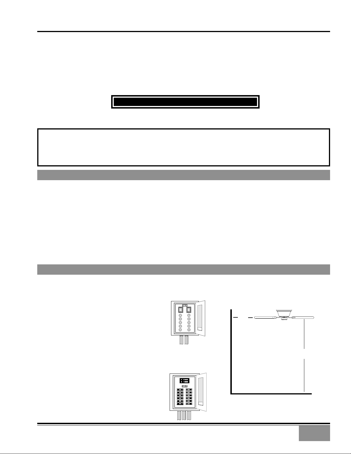
SAFE USE
FUSE BOX
(REMOVE FUSE FOR THE
CIRCUIT YOU WILL BE
WORKING ON)
CIRCUIT BREAKER
(TRIP BREAKER FOR THE
CIRCUIT YOU WILL BE
WORKING ON)
18"
84"
1
FOUR SEASONS™ III HUGGER
MOUNTING RECOMMENDATIONS
Before mounting your Casablanca fan, read the following helpful recommendations. The location of the fan, air circulation,
and fan size are all important factors to consider before installation.
Location
Ceiling fans have practical uses in almost every room in your home. We suggest you follow these mounting
recommendations as you decide where to install your Casablanca fan.
• For safety reasons, the fan blades must be a minimum of 7' above the floor.
• Do not locate the fan in a doorway or above a swinging door.
• In any installation, the tips of the blades must be at least 18" from the wall in order to
provide sufficient clearance for the blades.
• In bedrooms, fans work best when mounted above the foot of the bed.
• Over pool tables, be sure to provide plenty of clearance to avoid damage from
pool cues.
• In kitchens be sure to allow for open cupboard doors to clear the fan blades.
• Do not install a fan close to, or over, a pool or spa. High humidity combined with
corrosive gases will destroy the finish and warp the blades.
Fan Size
Variable fan speed capability permits the use of a full-size 52" fan even in
smaller rooms. For very large rooms, two fans may be needed.
PREPARATION INSTRUCTIONS
Unpacking: Before assembling and installing your ceiling fan, remove all parts from the shipping cartons and check them
against the parts listed here. Before discarding packaging material, be certain that all parts have been removed.
Carton Contents
The fan carton contains the fan body, warranty card, owner's
manual, and all the parts necessary to assemble and install
your Casablanca ceiling fan. These parts are shown at the
start of each installation section. Before you start, go through
this Owner’s Manual and confirm that you have all the parts
shown in each section.
Be sure to use only genuine Casablanca blades. The blade
shrink wrap holds 5 blades of matched weight. If more than
one fan is being installed, be sure not to mix blade sets.
CAUTION: When removing the shrink wr ap,
be careful not to scratch the blades.
GETTING STARTED
Installing a New Ceiling Fixture Outlet Box
If you do not have an existing fixture located where you
wish to place your Casablanca fan, an approved ceiling fixture
outlet box must be installed and wired.
WARNING: To r educe the risk of fire , electrical shock,
or personal injury, mount to outlet box marked
acceptable for ceiling fan support using the
mounting hardware provided with the outlet box.
Using Existing Ceiling Fixture Outlet Box
After turning the power OFF at its source (either circuit breaker
or fuse box), lower the old fixture and disconnect the wiring.
Check the ceiling fixture outlet box to be sure that it is
marked ‘Approved for ceiling f an mounting’. If it is not, a new
box must be installed.
NOTE: The fan weight is 17 pounds.
2
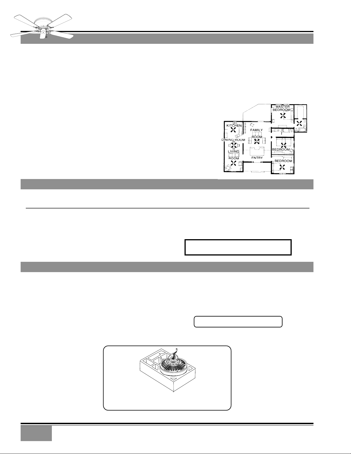
TIP: The packing styrofoam makes a handy work bench.
Remove the bottom foam from the box.
FOUR SEASONS™ III HUGGER
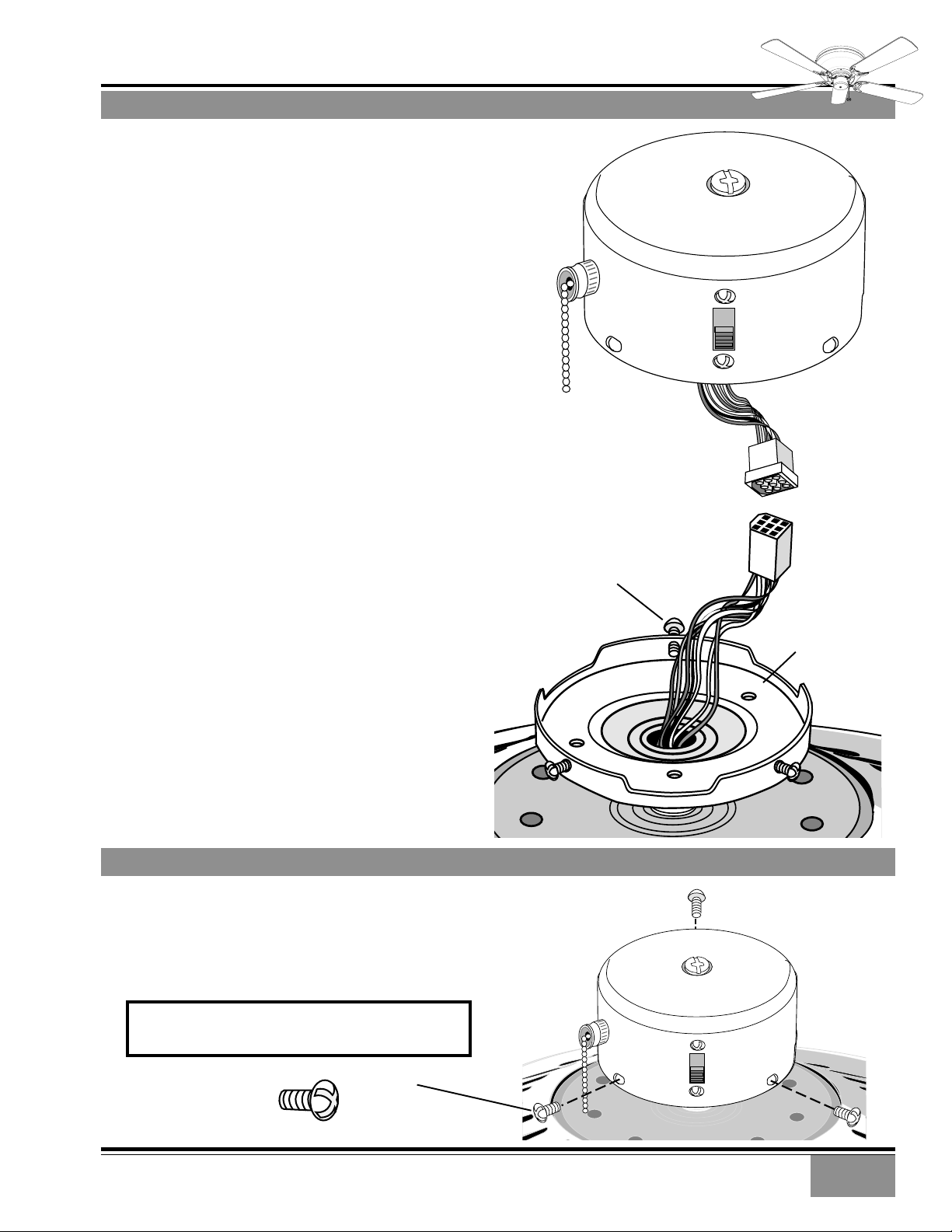
SWITCH HOUSING INSTALLATION
Step 1. Hold the switch housing close to the fan and
connect the motor plug to the switch housing socket.
The connectors are keyed to ensure correct alignment
during installation - Do not force!
Step 2. Remove the three mounting screws from the
switch housing plate ready for the next step.
SWITCH
HOUSING
MOUNTING
SCREW
(3)
MOTOR
CONNECTOR
(PLUG)
SWITCH
HOUSING
CONNECTOR
(SOCKET)
SWITCH
HOUSING
PLATE
SWITCH HOUSING INSTALLATION
Step 3. Position the switch housing assembly on the
switch housing plate and align the holes in the switch
housing with the holes in the plate. Secure the switch
housing assembly by reinstalling the three screws
removed in the previous step.
CAUTION! Do not pinch wires between the switch
housing assembly and the plate.
MOUNTING
SCREW
(3)
3

FOUR SEASONS™ III HUGGER
INSTALLING THE MOUNTING PLATE
Step 4. Carefully feed the ceiling wires through the
center hole of the mounting plate then securely
attach the mounting plate to the outlet box using
the two 8-32 round head screws with star washers
supplied. Make sure the hook and threaded studs
are pointed downward.
CEILING OUTLET
BOX
CAUTION: To reduce the risk of personal
injury use only the two steel screw s (with
locking star washers) provided with the
fan for mounting to the ouutlet box.
Step 5. Check that the mounting plate is seated
firmly against the ceiling and that none of the ceiling wires have been pinched by the plate.
If the mounting plate and/or junction box are not
securely attached, the fan could wobble or fall.
REMOVE MOUNTING PLATE NUTS AND WASHERS
Step 6. Remove the four nuts and washers from
the mounting plate and set aside for use in
Step 12.
CEILING
WIRING
MOUNTING
PLATE
MOUNTING PLATE
SCREW AND
STAR WASHER
INSTALL STEEL BUSHINGS
Step 7. Prepare the motor for installation by at-
taching the steel bushings into the rubber bushings
so that their top surfaces are flush.
STEEL
BUSHINGS
4

FOUR SEASONS™ III HUGGER
HANGING THE FAN TEMPORARILY
Step 8. Use the hanging slot of the mounting bracket
to hang the fan on the hook of the mounting plate.
This will help you in making the electrical connections.
WIRING PRELIMINARIES
Step 9. To avoid possible electric shock, be sure
electricity is turned off at the main fuse box or
breaker before wiring.
CAUTION: If you are not sure that the
ceiling outlet box is grounded, contact a
licensed electrician for advice. It must
be grounded for safe operation.
Step 10. Connect the green grounding lead from
the motor bracket and hanging bracket to the grounding conductor of the supply from the ceiling (this
may be a bare copper or green Insulated wire) using
the wire nut provided.
HANGING
BRACKET
MOTOR
BRACKET
5

FOUR SEASONS™ III HUGGER
CONNECTING THE WIRING
Step 11a. Attach the fan wires to the ceiling fixture
outlet box wiring by twisting the bare ends of the
wires together and then securing twith a wire nut.
Test that the connection is secure by pulling ou the
wire nut. Connect in this order:
• GREEN leads from the mounting plate and fan to
GROUND conductor of power source. Secure with
wire nut.
• WHITE wire from fan to white NETURAL wire in
ceiling fixture outlet box. Secure with wire nut.
• BLACK & BLUE wires from fan to black (*or red)
POWER wire in ceiling fixture outlet box. Secure
with wire nut.
Step 11b. Tuck the wires into the outlet box with
the wirenuts pointed upward
NOTE: If you are using an optional light
fixture with your fan, see Light Fixture
Instruction sheet for wiring.
2 GREEN
2 WHITE
BLUE AND
2 BLACK
WIRE NUTS
(3)
FINAL ATTACHMENT
Step 12. Match the four holes at both ends of the
mounting bracket with the four threaded studs of
the mounting plate. Assure that no wires are pinched.
Secure the fan assembly to the mounting plate using the washers and nuts removed in Step 6.
FLAT WASHER
SELF LOCKING
NUT
BODY COVER ATTACHMENT
Step 13. Lift the body cover to the mounting plate and
align the two pairs of mounting holes in the fan body
with the threaded holes in the ceiling mounting plate.
6
BODY COVER
BODY
MOUNTING
HOLES

FOUR SEASONS™ III HUGGER
BODY COVER ATTACHMENT
Step 14. Secure the body cover to the mounting plate
using the four 4mm x 1⁄4" screws. Tighten firmly to
avoid noise and vibration.
MOUNTING
SCREWS (4)
BLADE & BLADE HOLDER HARDWARE
BLADE & BLADE HOLDER HARDWARE
BLADE
HOLDER
BLADE & BLADE HOLDER INSTALLATION
Step 15. Attach the blades to the
blade holders with the three blade
screws and flat washers provided
for each blade.
Hand tighten securely.
Install the assembled blade and
blade holder to the fan motor.
Hand tighten securely.
Repete for each assembly.
Step 16. Attach the pull chain fob.
BLADE SCREW
(3 PER BLADE)
FLAT WASHER
(3 PER BLADE)
BLADE HOLDER SCREW
(2 PER BLADE)
BLADE SCREW
(3 PER BLADE)
FLAT WASHER
(3 PER BLADE)
FOB
BLADE HOLDER
SCREW
(2 PER BLADE
HOLDER)
7

3-SPEED
3-SPEED ♦ W-4 WALL CONTROL OF THE FAN
• The W-4 allows the choice of four (4)
different speed settings.
• No light fixture is used.
• Set the FAN pull chain switch to the
HIGH speed setting.
• No changes in household or fan wiring
are required.
• The fan may be turned ON and OFF by
the W-4 wall control.
CAUTION! Failure to set the pull-chain
speed to HIGH can result in faulty
operation of the fan and damage to
the W-4 wall control. To confirm fan
is set to HIGH: Turn W-4 fan speed
switch to 'HI' - set fastest fan speed
with pull chain.
R
3-SPEED ♦ W-8 WALL CONTROL OF THE FAN & LIGHT(S)
• The fan may be turned ON and OFF
by the W-8 wall control.
• The lights may be turned ON and
OFF by the W-8 and the intensity
adjusted from low to high.
• The fan must be supplied with two
independent 120V AC supply
wires.
• Set the FAN pull chain switch to
the HIGH speed setting.
• Turn the lights ON at the fan.
• The W-8 allows the choice of four
(4) different speed settings.
CAUTION! Failure to set the pullchain speed to HIGH can result in
faulty operation of the fan and
damage to the W-8 wall control.
To confirm f an is set to HIGH: Turn
W-8 fan speed switch to 'HI' - set
fastest fan speed with pull chain.
8

3-SPEED ♦ OPERATION
3-SPEED
Pull-chain switches on the fan control the fan and lights.
Using the fan control pull-chain switch: Fan off at start.
• First pull: fan ON, low speed
• Second pull: medium speed
• Third pull: high speed
• Fourth pull: fan OFF
Using the optional light pull-chain switch: Light off at start.
• First pull: light ON
• Second pull: light OFF
Direction of blade rotation is controlled by the reverse slide
switch on the side of the switch housing.
No changes in household wiring are required.
OPTIONAL LIGHT
PULL CHAIN
SWITCH
REVERSE
SWITCH
3-SPEED ♦ OPTIONAL WALL CONTROL ♦ W-4
The W-4 wall control provides four-speed control of fan from a convenient wall location. The
W-4 is designed to replace a standard wall switch and will fit wall boxes with a depth of 2"
or greater. Not for use with single pull-chain fan/light option wiring.
To install a W-4 wall control in place of an existing wall switch, follow the instructions on
the W-4 package.
Note: No rewiring is required if the fan is replacing an existing light fixture.
Operation of the fan from the wall switch is simple:
1. Turn knob to obtain desired speed setting.
CAUTION! Failure to set the pull-chain speed to HIGH can r esult in faulty oper ation o f
the fan and damage to the W-4 wall contr ol. To confirm f an is set to HIGH: Turn W-4 f an
speed switch to 'HI' - set fastest fan speed with pull chain.
FAN & SPEED
CONTROL
PULL CHAIN SWITCH
R
3-SPEED ♦ OPTIONAL WALL CONTROL ♦ W-8
The W-8 wall control provides separate control of fan and light with two separate knobs from
a convenient wall location. The W-8 is designed to replace a standard wall switch and wall
boxes with a depth of 2" or greater. Requires two hot leads from wall box to ceiling wiring
box.
To install a W-8 wall control in place of an existing wall switch, follow the instructions on
the W-8 package.
Operation of the fan from the wall switch is simple:
1. Turn the upper knob to the desired fan speed.
2. Turn the lower knob to the desired light setting.
CAUTION! Failure to set the pull-chain speed to HIGH can r esult in faulty oper ation o f
the fan and damage to the W-8 wall contr ol. To confirm f an is set to HIGH: Turn W-8 f an
speed switch to 'HI' - set fastest fan speed with pull chain.
SAVING MONEY WITH YOUR CEILING FAN
IN SUMMER, the movement of
air creates a cooling “wind chill”
effect. A room can actually feel
several degrees cooler , without setting the thermostat lower.
IN WINTER, hot air rises to the
ceiling while cool air settles to the
floor. Trapped against the ceiling,
the warm air is wasted. If you turn
up the thermostat, energy costs
will rise.
LO
RUNNING IN REVERSE, your
Casablanca fan can recirculate
warm air near the ceiling down
into the living area, providing even
heating and comfort (with a pleasant effect on heating bills).
9

3-SPEED
Please follow this troubleshooting guide before contacting your dealer for assistance.
TROUBLESHOOTING
BEFORE REQUESTING SERVICE:
Caring for Finishes: For cleaning, a soft brush or lint-free cloth
should be used to prevent scratching the finish. A vacuum cleaner
brush nozzle can remove heavier dust. Surface smudges or an accumulation of dirt and dust can easily be removed by using a mild
detergent and slightly dampened soft cloth. An antistatic agent
may be used, but never use abrasive cleaning agents. These will
damage the finish. Painted and high-gloss blades may be cleaned
in the same manner.
Blades: Wood finish blades should be cleaned with a furniture polishing cloth. Occasionally, a light coat of furniture polish may be
applied for added protection and beauty.
Never Lubricate this Fan!
The precision motor at the heart of your Casablanca fan features
sealed bearings that are lubricated for life. Do not attempt to oil
the motor.
Changing Light Bulbs
Be sure to turn power to the fan OFF at the wall switch or circuit
breaker before changing light bulbs. Replace bulbs with same type
as removed from the fixture. Each fan is rated for a maximum TOTAL
wattage of lighting.
Exceeding the rated maximum allowable wattage for the fan will
burn out the fan electronics module and void the warranty.
PROBLEM POSSIBLE REMEDIES..3-SPEED
FAN WILL NOT START Check main circuit fuses, circuit breakers, or wall switch position.
Check all wire connections, making sure the power is turned off during this inspection.
Check that reverse switch is not set in center of throw.
FAN WOBBLES OR SHAKES Be sure canopy pin is properly set into the slot on the ball.
EXCESSIVELY Check the screws holding the blade holders to the flywheel (or direct drive motor). Tighten as necessary.
Check that bladeholders have not been bent during installation.
FAN NOISY DURING Check and tighten light fixture retaining screws, glass shade screws and/or the light bulb(s) as neccessary.
OPERATION Tighten the blade to bladeholder screws.
Tighten canopy screws and mounting plate assembly.
Check and tighten blade holders to flywheel (or direct drive motor).
Make sure all screws in the motor housing are snug, but not overly tight.
Check that the wire nuts inside the canopy and switch housing are not touching the metal parts or have
fallen off the wire splices. Tighten or adjust as necessary.
BREAK-IN PERIOD Let fan run at high speed for two (2) hours
DOES NOT RUN ON If new, “break-in” may be required - run at higher speed for several days
LOW SPEED
FAN RUNS SLOWLY IN EITHER DIRECTION IF ROTATION IS STARTED BY HAND; WILL NOT REVERSE: Defective reverse switch; defective
capacitor; or open motor winding: Replace reverse switch assembly; replace PCB assembly; or replace motor unit.
FAN WILL NOT OPERATE AT PROPER SPEEDS OR WILL NOT OPERATE AT ANY SPEED: Defective three-speed pull-chain switch assembly; or
defective capacitor: Replace three-speed pull-chain switch assembly; or replace PCB assembly.
For questions or to locate the nearest
Casablanca Authorized Service Center
call toll free:
1-888-227-2178
or visit us on the web at:
www.CasablancaFanCo.com
10

761 CORPORATE CENTER DRIVE • POMONA, CA 91768
TOLL FREE: 888-CASA-1ST (227-2178)
www.CasablancaFanCo.com
©COPYRIGHT 1999 C ASABLANCA FAN COMPANY • U.S. P ATENT PENDING
PRINTED IN ROC
 Loading...