

™
CAMPANA
OWNER’S MANUAL
3-Speed Model Only
CONTENTS
INTRODUCTION . . . . . . . . . . . . . . . . . . . . . . . . . . . . . . . . . . . . . . . . . . . . . . . . . . . . . . . . . . . . . . . . . . . . . . 1
MOUNTING RECOMMENDATIONS . . . . . . . . . . . . . . . . . . . . . . . . . . . . . . . . . . . . . . . . . . . . . . . . . . . . . . . . . . 2
PREPARATION INSTRUCTIONS . . . . . . . . . . . . . . . . . . . . . . . . . . . . . . . . . . . . . . . . . . . . . . . . . . . . . . . . . . . 3
FAN INSTALLATION . . . . . . . . . . . . . . . . . . . . . . . . . . . . . . . . . . . . . . . . . . . . . . . . . . . . . . . . . . . . . . . . . . . 4
CONTROL FEATURES:
3-SPEED OPERATION . . . . . . . . . . . . . . . . . . . . . . . . . . . . . . . . . . . . . . . . . . . . . . . . . . . . . . . . . . . . . . . 10
VERSA•TOUCH2 OPERATION . . . . . . . . . . . . . . . . . . . . . . . . . . . . . . . . . . . . . . . . . . . . . . . . . . . . . . . . . . . 12
TROUBLESHOOTING . . . . . . . . . . . . . . . . . . . . . . . . . . . . . . . . . . . . . . . . . . . . . . . . . . . . . . . . . . . . . . . . . . . 14
READ AND SAVE THESE INSTRUCTIONS
SAFETY FIRST
Safety and the proper operation of y our Casablanca fan both requir e a thorough knowledge o f the product
and proper installation; therefor e, bef ore attempting to install and operate your Casablanca f an, read this
owner’s manual completely and carefully. Retain this manual for future reference.
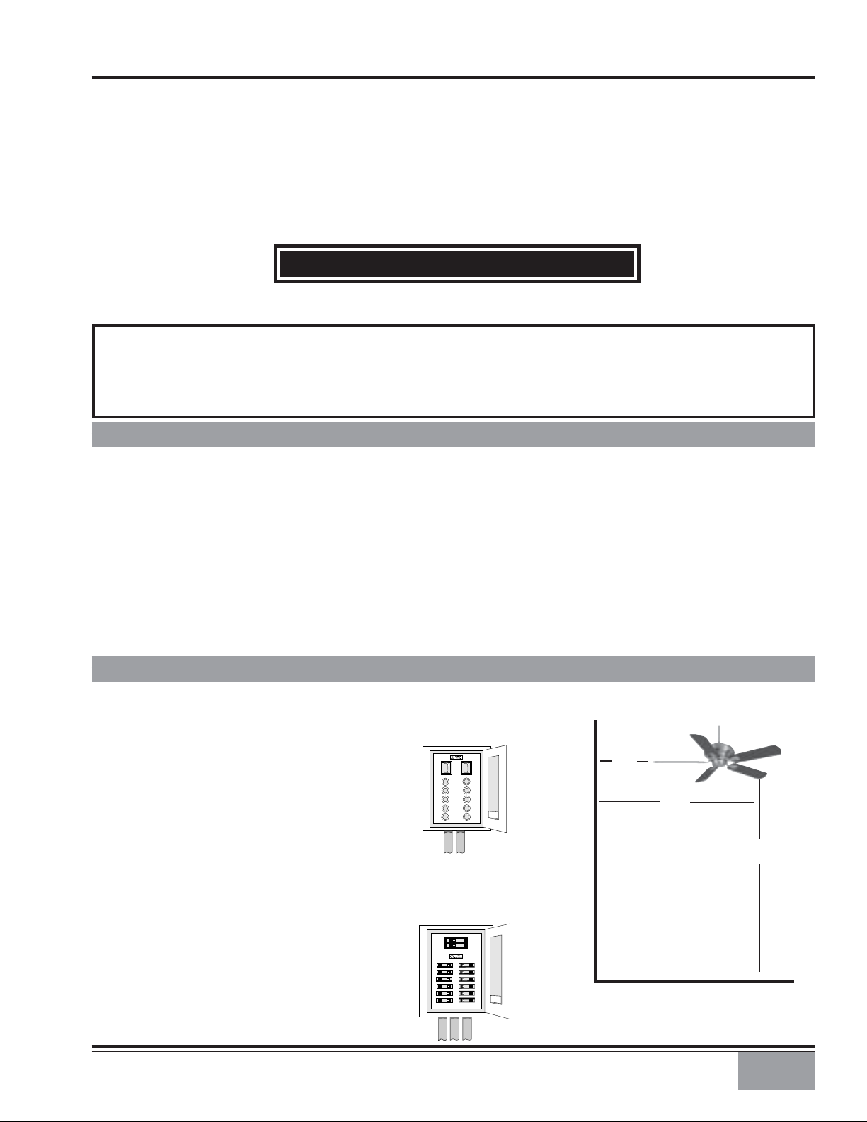
CAUTION: T o av oid possible electrical shock, make certain that electricity is turned o ff
at the circuit breaker or fuse box before attempting any installation procedure.
BEFORE YOU START
• All wiring must be in accord ance with th e Nation al Electric Cod e ANSI/NFP A 70-1993 an d the appr opriate local electri cal
codes. The N ati onal Electri c Code requires pr oper groun din g as a pr ecauti on again st electri cal sh ock. A qu alifi ed electrician should be consulted if you are unsure.
• This fan is design ed to be installed on an e xistin g electri cal outlet bo x. The outlet bo x m ust be UL Listed f or ceilin g fan
installations , if it is not, a new bo x must be in stalled. Casablanca e xtensi on poles are available f or sloped or high ceiling
installations.
• This ceiling fan requires a grounded electrical supply of 120 VAC, 60 Hz and a minimum 15 amp circuit. The maximum
current requirement for the fan with light fixture is 3.8 amps. The fan uses about 1 amp or 100 watts. Maximum light
current is 2.8 amps or 340 watts of lighting.
• Where wire n uts are employed , be sure all bar e wir es are within th e conn ectors. Wh en installin g th e canopy hatch, m ak e
sure all wires are within the canopy and that no wires are being pinched.
For best performance and for your warranty to be valid,
use only genuine Casablanca blades, light fixtures, and accessories.
• The blades in each pack are m atched for equal
weight to assure smooth fan operation. If
more than one fan is being installed, be
careful not to mix blades from different
cartons.
• Inspect the contents of your carton for
possible shipping or handling damage and
report any such damage directly to your
authorized Casablanca dealer.
• It is always a good idea to have an assistan t
to help with the installation.
• When cleaning, painting, or working near
your fan, be very careful of th e fan and blades.
Always turn the power OFF to the ceiling f an
before servicin g it, working on it, or replacing
light bulbs.
• Never insert anything into the path of the
fan blades while the fan is in operation.
•Never install a fan over a pool or spa.
• Never operate a fan that has been damaged
in any way . Contact Casablanca Fan Compan y
by calling toll free 1-888-227-2178, or
contact your local authorized Casablanca
dealer for assistance in obtaining service.
P/N 9143010 REV. C BM1103
SAFE USE
FUSE BOX
(REMOVE FUSE FOR THE
CIRCUIT YOU WILL BE
WORKING ON)
18″
70″
84″
CIRCUIT BREAKER
(TRIP BREAKER FOR THE
CIRCUIT YOU WILL BE
WORKING ON)
1
MOUNTING RECOMMENDATIONS
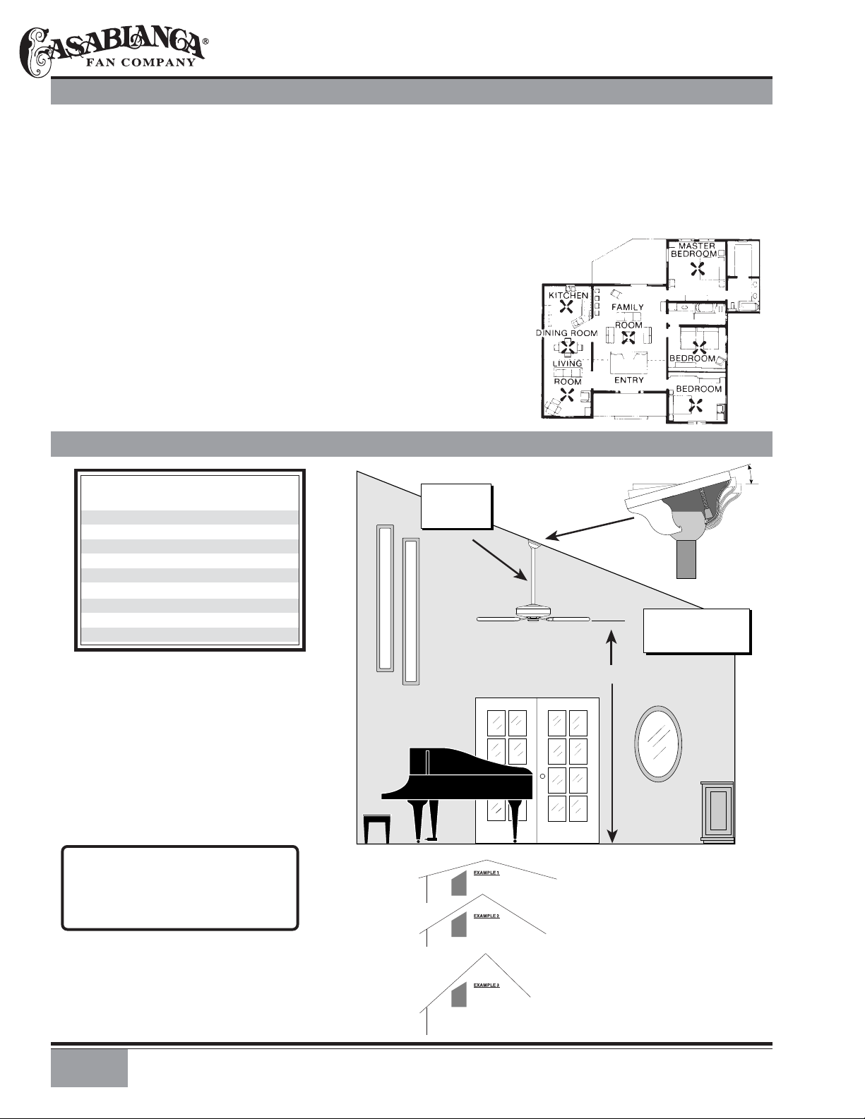
Before moun ting your Casablan ca f an, read th e f ollowing h elp ful recomm en dati on s. Th e locati on of th e f an, air circulati on,
and fan size are all important factors to consider before installation.
Location
Ceiling fans have pr actical uses in alm ost every r oom in your h om e . We suggest you follow th ese m ounting recommendations as you decide where to install your Casablanca fan.
• For safety reasons, the fan blades must be a minimum of 7′ above the floor.
• Do not locate the fan in a doorway or above a swinging door.
• In any installation, the tips of the blades must be at least 18″ from the wall in order to provide
sufficient clearance for the blades.
• In bedrooms, fans work best when mounted above the foot of the bed.
• Over pool tables, be sure to provide plenty of clearance to avoid damage from
pool cues.
• In low ceiling locations, our optional Low Ceiling Adaptor (LCA)—available at
extra cost—can be used to gain 31/2″.
• In kitchens be sure to allow for open cupboard doors to clear the fan blades.
• Do not install a fan close to, or over, a pool or spa. High humidity combined
with corrosive gases will destroy the finish and warp the blades.
Fan Size
Variable f an speed capability permits the use o f a full-size 52 ″ fan even in
smaller rooms. For very large rooms, two fans may be needed.
SLOPED CEILING INSTALLATIONS
Suggested Extension Pole Lengths
Ceiling Height
8′
8′ 6″
9′
9′ 6″
10′
11′
12′
13′
14′
Pole Length
Standard
Standard
6″
12″
12″
18″
24″
36″
48″
EXTENSION
POLE
MAXIMUM
HANG-TRU®
ANGLE 32º
BLADES MUST BE A
MINIMUM OF 7′
ABOVE THE FLOOR
32°
When to Use Extension Poles
For best performance an d best appear ance ,
an extension pole sh ould be used with your
Casablanca fan when in stalling on high (cathedral) ceilings or sloped ceilings.
Casablanca offers standard poles in increments of 6″ up to 5′. Custom poles are
available in lengths up to 9′9″. See your
Authorized Casablanca Dealer for details.
Note: Fan may wobble or vibrate if pole
length is not long enough and inside
blade is too close to downslope or side
wall. Extending pole length will usually
solve problem.
Calculation of 32°
Use the tear-off Ceiling Angle Template car d in serted in th e
back of this manual, it provides you with a simple ‘go’ or
‘no-go’ for installing your fan on a sloped ceiling.
2
7′ MINIMUM
EXAMPLE 1
This slope is less than 32˚.
It is OK to install your fan.
EXAMPLE 2
This slope is 32˚. This is the maximum
slope that will allow the fan to hang
straight down. It is OK to install your
fan.
EXAMPLE 3
This slope is more than 32˚.
Your fan will n ot han g str ai gh t down, an
adaptor is necessary. Contact your local
Authorized Casablanca Dealer in regards
to purchasing a “Slope Ceiling Adaptor.”
CAMPANA
™
PREPARATION INSTRUCTIONS
Unpacking: Before assembling and installing your ceiling fan, remove all parts from the shipping cartons and check them
against the parts listed here. Before discarding packaging material, be certain that all parts have been removed.
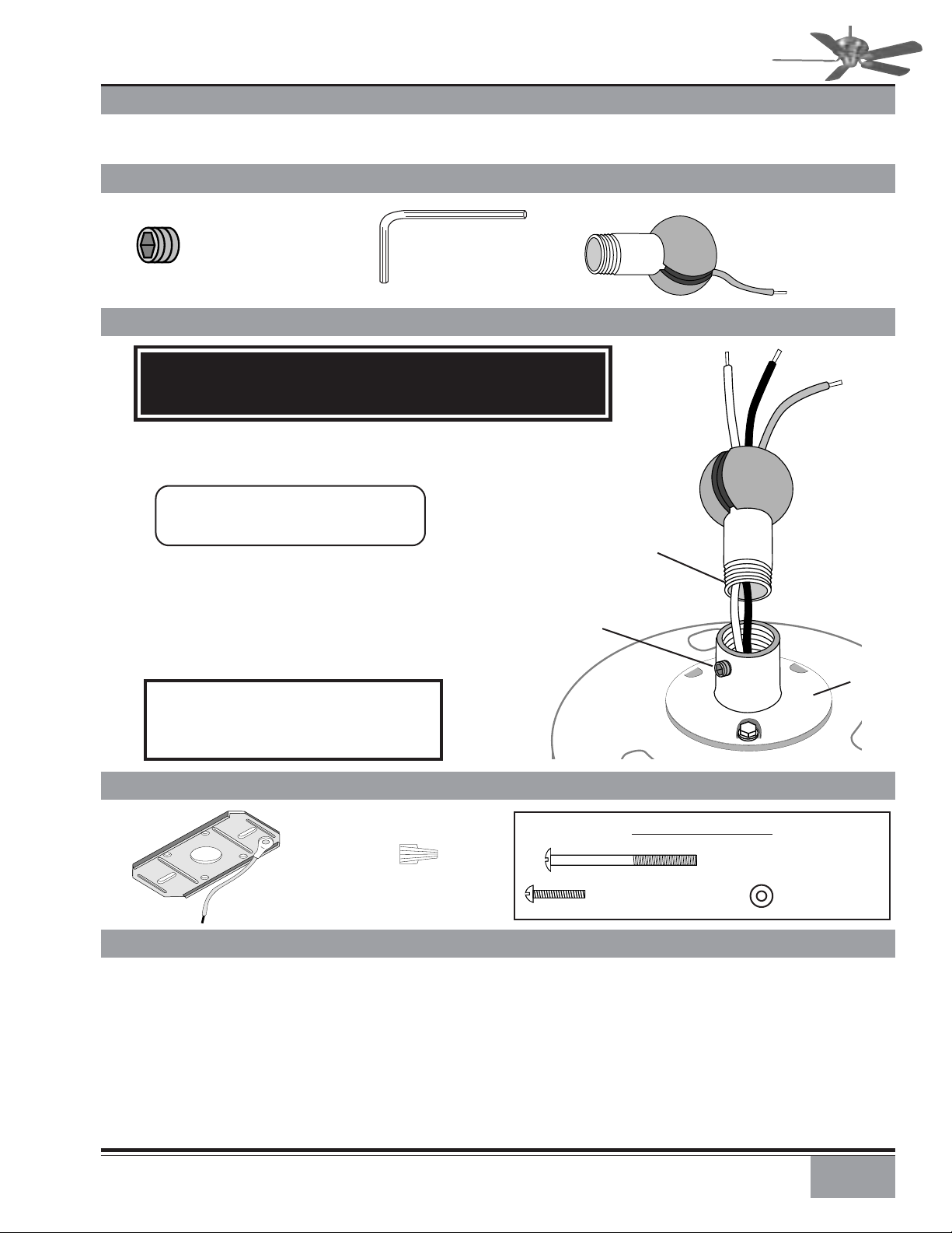
PERMA•LOCK™ HARDWARE
ALLEN SET SCREW
1
⁄4-20 x 1⁄4"
(PRE-INSTALLED)
3mm
ALLEN WRENCH
FAN PREPARATION
IMPORTANT SAFETY INFORMATION!
BEFORE STARTING THE INSTALLATION OF YOUR CEILING FAN, INSTALL THE
THREADED DOWNROD INTO THE MOTOR COUPLING AND LOCK THE ASSEMBLY
Prepare for fan installation as follows:
Step A. Route the wires from the motor through the
Perma•Lock™ downrod and ball assembly.
Tip: The downrod has a tapered thread
that is designed to lock completely wh en
correctly installed.
Step B. Usin g the provid ed allen wrench, loosen the set scr ew
several turns to allow installation of the downrod. Thread
the downrod into the motor coupling until it stops turning,
this will take at least four and a half full turns.
Step C. Securely tighten th e set screw with the provi ded allen
wrench to ensure safe operation of your fan.
CAUTION: Failure to fully lock in the do wnrod before secur ely tightening the allen set
screw may cause the fan to separate from
the downrod during normal operation!
DOWNROD & BALL
ASSEMBLY
MOTOR
WIRES
GROUND
WIRE
DOWNROD
& BALL
ASSEMBLY
TAPERED
THREAD
ALLEN
SET SCREW
MOTOR
COUPLING
CEILING HARDWARE
CROSSBAR
MOUNTING
BRACKET
WIRE NUT (4)
GETTING STARTED
Installing a New Ceiling Fixture Outlet Box
If you do not have an existin g fixture located where you wish
to place your Casablanca fan, an approved ceiling fixture
outlet box must be installed and wired.
Warning: To reduce the risk of fire, electrical shock,
or personal injury, mount to outlet box marked
acceptable for ceiling fan support using the mounting hardware provided with the outlet box.
ADDITIONAL HARDWARE
1
2
/4″ x 8-32 ROUNDED
HEAD SCREW (2)
1″ x 8-32 ROUNDED
HEAD SCREW (2)
Using Existing Ceiling Fixture Outlet Box
After turning the power OFF at its source (eith er circuit breaker
or fuse box), lower the old fixture an d disconnect the wiring.
Check the ceiling fixture outlet box to be sure that it is
marked ‘Approved for ceiling f an mounting’. If it is not, a new
box must be installed.
FLAT WASHER (2)
3
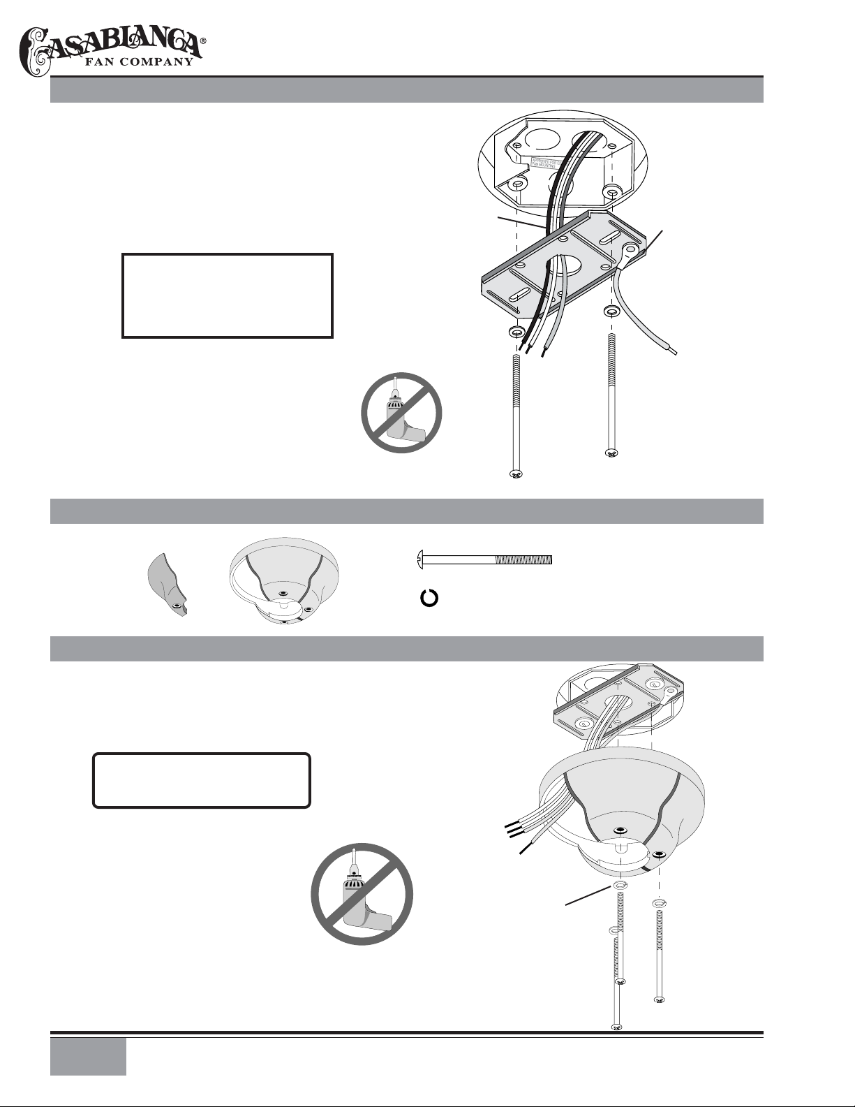
CROSSBAR MOUNTING BRACKET INSTALLATION
Proceed with installation as follows:
Step 1. Route the wires fr om th e ceilin g outlet bo x thr ough
the crossbar moun ting bracket center h ole. Attach th e bracket,
with ground wire an d ridg es down, to the ceiling fixtur e outlet box with the moun ting hard ware inclu ded with the outlet
box.
Tighten the scr ews firmly by hand only , bein g careful n ot to
bend the bracket by over tightening.
CAUTION: To reduce the risk of
personal injury, use only the
mounting hardware pr ovided with
the approved outlet bo x to install
the crossbar mounting bracket.
CANOPY HARDWARE
CEILING FAN
APPROVED
OUTLET BOX
CEILING
WIRING
CROSSBAR
MOUNTING
BRACKET
WASHER
RIDGE
SIDE
DOWN
FLAT
GREEN
GROUND
WIRE
OUTLET BOX
MOUNTING
HARDWARE
CANOPY
HATCH
CANOPY
CANOPY INSTALLATION
Step 2. Attach the canopy to the cr ossbar mount-
ing bracket with three of the 8-32 x 2
canopy screws and canopy lock washers.
Tighten the screw firmly by hand only.
Note: On sloped ceilings, align the
canopy opening towards the top or
room peak.
1
/4″ long
CANOPY SCREW (4)
CANOPY LOCK WASHER (4)
CROSSBAR MOUNTING
BRACKET INSTALLED
CANOPY
CANOPY LOCK
WASHERS
4
CANOPY
SCREWS
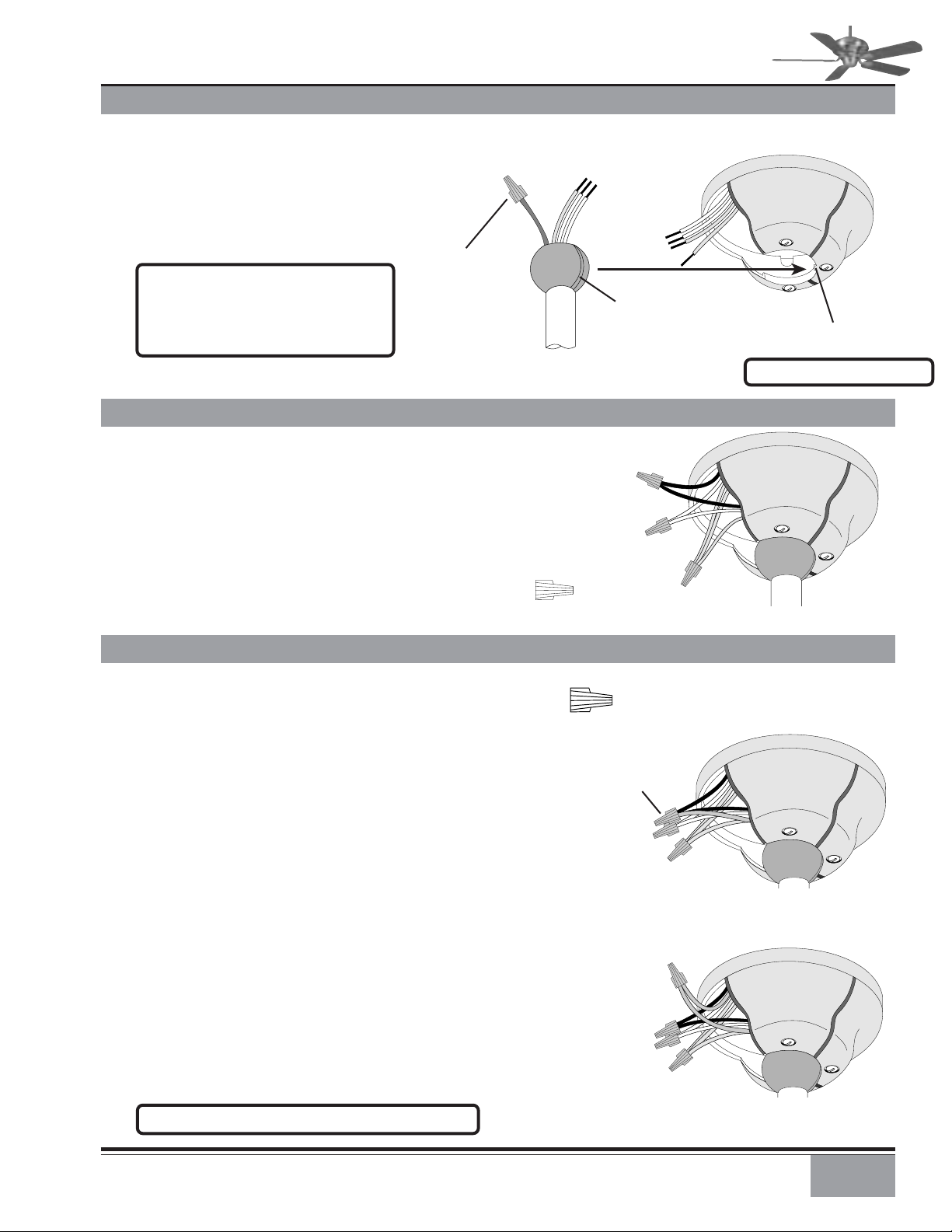
HANGING THE FAN
Step 3. To hang the fan body in the
canopy , h old the fan bod y firmly and insert the ball into the canopy opening.
Check that no wires were pinched. Rotate the fan body until the slot in the
ball fits into the pin opposite the can opy
opening.
CAPPED
3-Speed Note: Independent control of
the light fixture using a W-80 requires
an additional independent power wire
run from the wall switch to the fan. See
Page 10 for wiring.
BLUE
D1-OPTION
WIRE ON
3-SPEED ONLY
FOR INDEPENDENT
W-80 LIGHT
CONTROL
VERSA•TOUCH2 CANOPY ELECTRICAL CONNECTIONS
Versa•Touch2 Step 4. Attach the fan wires to the ceiling
fixture outlet box wiring by twisting the bare ends of the
wires together an d securin g with a wir e nut. Conn ect in this
order:
CAMPANA
BALL
SLOT
BLACK WIRES
(2)
™
PIN
Note: Fan weight is 22 lbs.
• GREEN leads from mounting plate and fan to GROUND
conductor of power source. Secure with wire nut.
• WHITE wire from fan to white NEUTRAL wire in ceiling
fixture outlet box. Secure with wire nut.
• BLACK wire from fan to black (or red) POWER wire in
ceiling fixture outlet box. Secure with wire nut.
3-SPEED CANOPY ELECTRICAL CONNECTIONS
3-Speed Step 4a. Attach th e fan wir es to the ceilin g fixtur e
outlet box wiring by twisting the bare ends of the wires together and then securing with a wire nut. Test that the
connection is secure by pulling on the wire nut. Connect in
this order:
Step 4b. Pull Chain or W-40 Wiring Connections
• GREEN leads from mountin g plate and fan to GROUND conductor of power source. Secure with wire nut.
• WHITE wire from fan to white NEUTRAL wire in ceiling
fixture outlet box. Secure with wire nut.
• BLUE wire and BLACK power wir e from fan to BLACK power
wire in ceiling outlet box. Secure with wire nut.
Step 4c. W-80 Wiring Connections
• GREEN leads from mountin g plate and fan to GROUND conductor of power source. Secure with wire nut.
• WHITE wire from fan to white NEUTRAL wire in ceiling
fixture outlet box. Secure with wire nut.
• BLACK power wire from f an to RED wire from W-80 in ceiling outlet box. Secure with wire nut.
• BLUE wire from fan to YELLOW wire from W-80 in ceiling
outlet box. Secure with wire nut.
WHITE WIRES
(2)
WIRE NUT
WIRE NUT
2 BLACK & BLUE
D1-OPTION WIRES
(WITHOUT W-80)
2 WHITE WIRES
3 GREEN WIRES
BLUE & YELLOW
WIRES
BLACK & RED
2 WHITE WIRES
GREEN WIRES
(3)
PULL CHAIN OR
W-40 CONNECTIONS
W-80 CONNECTIONS
WIRES
3 GREEN WIRES
NOTE: See page 10 for additional wiring information.
5

CANOPY HATCH INSTALLATION
Step 5. Tuck the wires into the canopy
with the wire nuts pointed upwards, so
that the WHITE and BLACK wires are on
opposite sides of th e canopy and all wires
are clear of the canopy opening.
Step 6. Install canopy hatch with th e last
canopy screw and lock wash er . To do this ,
tilt the fan body away from the hatch
opening.
Tighten the screws firmly by hand only,
CANOPY
HATCH
LOCK
WASHER
CANOPY
SCREW
Step 7. Straighten the fan, then check
to ensure that ther e is no m ovemen t between the canopy and ceilin g or Hang-Tru
ball and top support shaft.
REMOVE SHIPPING BLOCKS
Step 8. Unscrew an d rem ove the 5 shippin g
blocks. Y ou can discar d th ese 5 scr ews an d
the shipping blocks.
The shipping blocks are used only when
shipping the fan.
Note: Write down the
Serial Number and the
model number for future
reference.
TILT THE
FAN TO
INSTALL
LAST
CANOPY
SCREW
SHIPPING
BLOCKS
6
BLADE & BLADE HOLDER HARDWARE
BLADE SCREW
(4 PER BLADE)
WASHER
(4 PER BLADE)
BLADE HOLDER
SCREW
(2 PER BLADE)
BLADE
HOLDER

CAMPANA
BLADE TO BLADE HOLDER INSTALLATION
™
Step 9. Attach each blade to a blade
holder securing it with the four steel
washers and blade screws provided.
Tighten securely by hand only.
INSTALL BLADE ASSEMBLY TO FAN
Step 10. Attach each blade/blade holder
assembly to the motor.
Tighten securely by hand only.
BLADE SCREW
(4 PER BLADE)
WASHER
(4 PER BLADE)
BLADE
BLADE
HOLDER
ROTATE FLYWHEEL
TO INSTALL
BLADE HOLDER
SCREWS
BLADE HOLDER
SCREW
(2 PER BLADE)
SWITCH HOUSING ASSEMBLIES
3-SPEED
SWITCH HOUSING
AND CAP ASSEMBLY
SWITCH HOUSING
AND CAP ASSEMBLY
VERSA•TOUCH2
7

3-SPEED ONLY: ATTACHING SWITCH HOUSING WIRES
Step 11. For 3-Speed models only: Hold
the switch housing up to th e fan and connect the motor plug to th e switch housing
socket. The connector is k eyed to ensure
correct installation.
WARNING: Do not force the connectors– check that they are orientated so the keying will match!
Note: You may need to arrange the
electronics inside the switch housing
to make room for the connector.
INSTALL THE SWITCH HOUSING
Step 12 Remove the three screws on
the mounting plate. Line up the three
threaded holes in the rim of the switch
housing with the three clearance holes
in the mountin g plate. Carefully sli de the
switch housing intoth e mount so that the
threaded holes are directly behind the
clearance holes. Install the three scr ews
and tighten securely by hand only.
SWITCH
HOUSING
CONNECTOR
(SOCKET)
MOTOR
CONNECTOR
(PLUG)
CAUTION! Make sure that no wires
are pinched by the switch housing
before tightening screws.
8
MOUNTING
PLATE SCREWS
(3)

3-SPEED ♦ OPERATION
Pull-chain switches on the fan control the fan and lights.
Using the fan control pull-chain switch: Fan off at start.
First pull: fan ON, low speed
Second pull: medium speed
Third pull: high speed
Fourth pull: fan OFF
Using the opti onal light pull-chain switch: Li ght off at start.
First pull: light ON
Second pull: light OFF
Direction of blad e rotation is contr olled by the reverse slid e
switch on the side of the switch housing.
No changes in household wiring are required.
OPTIONAL LIGHT
PULL CHAIN
3-SPEED ♦ OPTIONAL LIGHT FIXTURE INSTALLATION
NOTE: If a separate circuit is used to control the lights from a wall
control, the BLUE D1-Option wire in the canopy should be connected
to that switch leg with the BLACK fan power wire.
1. Refer to light kit instructions to assemble and attach your light
kit correctly.
2. Remove the two 8-32 screws from the switch housing cap.
3. Remove the plug from switch housing.
4. Install pull-chain switch and finger tighten collar on switch.
5. Connect one wire from pull-chain switch to the BLUE D1-Option
wire. Secure splice with a wire nut.
6. Connect other wire from pull-chain switch to BLACK wire from
light kit. Secure splice with a wire nut.
7. Connect WHITE wir e from switch housin g to WHITE wire from ligh t
kit. Secure splice with a wire nut.
8. At the canopy, connect the BLACK and BLUE wires.
SWITCH
FAN & SPEED
CONTROL
PULL CHAIN SWITCH
REVERSE
SWITCH
SWITCH
HOUSING
COLLAR
3-SPEED OPTIONAL FAN ONLY WALL CONTROLS
The W-40 and W-24 wall controls provide four-speed control of fan from a convenient wall
location. The W-40 and W-24 are designed to replace a standard wall switch and will fit wall
boxes with a depth o f 2" or greater . Not for use with single pull-chain fan/light option wiring.
3-SPEED OPTIONAL FAN AND LIGHT WALL CONTROLS
The W-80 and W-28 wall controls provide separate control of fan and light with two separate
controls. Th e W-80 and W-28 are d esigned to replace a stan dard wall switch an d wall boxes with
a depth of 2" or greater. Requires two hot leads from wall box to ceiling wiring box.
3-SPEED OPTIONAL REMOTE CONTROL
Add remote control convenience to Casablanca 3-Speed fans. Adapt•Touch (W-52) easily converts new or existing Casablanca 3-speed Pull Chain fans equipped with a Hang-Tru canopy.
Features includ e three fan speeds, in stant off, and ful-ran ge ligh t dimming (on models equipped
with a light fixture). Th e han d-held remote includes a switch plate bracket for wall mounting,
and the receiver is quickly installed in the Hang-Tru canopy. Use one Adapt•Touch to control
several fans, or purchase extra controls to operate a fan from different locacations.
R
LO
9

OPTIONAL 3-SPEED W-40 WALL CONTROL
•The W-40 allows the ch oice of four
(4) different speed settings.
•No light fixture is used.
• Set the FAN pull chain switch to
the HIGH speed setting.
•No changes in household or fan
wiring are required.
•The fan may be turned ON an d OFF
by the W-40 wall control.
CAUTION! Failure to set the pull-chain
speed to HIGH can result in faulty
operation of the fan and damage to
the W-40 wall control. T o confirm f an
is set to HIGH: Turn W-40 fan speed
switch to 'HI' - set fastest fan speed
with pull chain.
R
OPTIONAL W-80 WALL CONTROL OF THE FAN & LIGHT
•The fan may be turned ON an d OFF
by the W-80 wall control.
•The lights may be turned ON and
OFF by the W-80 and the intensity adjusted from low to high.
•The fan must be suppli ed with two
independent 120V AC supply
wires.
• Set the FAN pull chain switch to
the HIGH speed setting.
•Turn the lights ON at the fan.
•The W-80 allows the ch oice of four
(4) different speed settings.
CAUTION! Failure to set the pull-chain
speed to HIGH can result in faulty
operation of the fan and damage to
the W-80 wall control. T o confirm f an
is set to HIGH: Turn W-80 fan speed
switch to 'HI' - set fastest fan speed
with pull chain.
10

TROUBLESHOOTING
Before Requesting Service: Please follow this troubleshooting guide before contacting your dealer for assistance.
Caring for Finishes: For cleaning, a soft brush or lint-free cloth
should be used to prevent scratching the finish. A vacuum cleaner
brush nozzle can remove heavi er dust. Surf ace smudges or an accumulation of dirt and dust can easily be removed by using a mild
detergent and slightly dampened soft cloth. An antistatic agent
may be used, but never use abrasive cleaning agents. These will
damage the finish. Painted and high-gloss blades may be cleaned
in the same manner.
Blades: Wood finish blades sh ould be cleaned with a furniture polishing cloth. Occasionally, a light coat of furniture polish may be
applied for added protection and beauty.
Never Lubricate this Fan!
The precision motor at the heart of your Casablanca fan features
sealed bearings that are lubricated for life. Do not attempt to oil
the motor.
Changing Light Bulbs
Be sure to turn power to the fan OFF at the wall switch or circuit
breaker before changing light bulbs . Replace bulbs with same type
as removed from the fixtur e. Each f an is rated for a maximum TOTAL
wattage of lighting.
Exceeding the rated maximum allowable wattage for the fan will
burn out the fan electronics module and void the warranty.
TROUBLESHOOTING
PROBLEM POSSIBLE REMEDIES..
FAN WILL NOT START •Check main circuit fuses, circuit breakers, or wall switch position.
PROBLEM
FAN WOBBLES OR SHAKES •Be sure canopy pin is properly set into the slot on the ball.
EXCESSIVELY •Check the screws holding the blade holders to the flywheel (or direct drive motor). Tighten as necessary.
•Check all wire connections, making sure the power is turned off during this inspection.
•Check that reverse switch is not set in center of throw.
•Check that bladeholders have not been bent during installation.
3-SPEED
POSSIBLE REMEDIES
FAN NOISY DURING •Check and tighten light fixture retaining screws, glass shade screws and/or the light bulb(s) as neccessary.
OPERATION •Tighten the blade to bladeholder screws.
•Tighten canopy screws and mounting plate assembly.
•Check and tighten blade holders to flywheel (or direct drive motor).
•Make sure all screws in the motor housing are snug, but not overly tight.
•Check that the wire nuts inside the canopy and switch housing are not touching the metal parts or have
fallen off the wire splices. Tighten or adjust as necessary.
BREAK-IN PERIOD •Let fan run at high speed for two (2) hours
DOES NOT RUN ON •If new, “break-in” may be required - run at higher speed for several days
LOW SPEED
FAN RUNS SLOWLY IN EITHER DIRECTION IF ROTATION IS STARTED BY HAND; WILL NOT REVERSE: Defective reverse switch; defective
capacitor; or open motor winding: Replace reverse switch assembly; replace PCB assembly; or replace motor unit.
FAN WILL NOT OPERATE AT PROPER SPEEDS OR WILL NOT OPERATE AT ANY SPEED: Defective three-speed pull-chain switch assembly; or
defective capacitor: Replace three-speed pull-chain switch assembly; or replace PCB assembly.
For questions or to locate the nearest Casablanca Authorized Service Center call toll free:
1-888-227-2178 or visit us on the web at: www.CasablancaFanCo.com
11

2
SAFETY FIRST
Warning: To reduce the risk of electrical shock this fan must be installed with an isolating wall control switch.
VERSA•TOUCH 2 ♦ INSTALLATION
W-72
CONTROL
W-72
CONTROL
HOLDER
12V BATTERY
DRYWALL
ANCHOR
6-32 (2)
WOOD
SCREW
1” (2)
SCREW
6-32 X
(2)
3
VERSA•TOUCH 2 ♦ CONTROL BRACKET INSTALLATION
CAUTION! Do not use with wall dimmer.
/8”
SCREW
6-32 X 1”
(2)
STANDARD
TOGGLE
SWITCH
INNER
MOUNTING
HOLES
SWITCH
COVER
PLATE
CONTROL
BRACKET
Standard Light Switch
Step A. Remove the two screws holding the switch cover
plate. Do not remove the cover plate.
Step B. Ori en t the con tr ol brack et as sh own an d line up th e
two inner mounting holes with those on the switch.
Step C. Install and tighten screws by hand only.
Wall Installation
Step A. Locate a 2x4 wall
stud in a convenient
location.
Step B. Orient the control
bracket as shown over the
2x4 stud.
Step C. Use the 1” wood
screws in either the inner
or outer mounting holes.
Install and tighten screws
by hand only.
ROCKER
TYPE
LIGHT
SWITCH
OUTER
MOUNTING
HOLES
SWITCH
CONTROL
BRACKET
COVER
PLATE
Rocker Light Switch
Step A. Break off the two tabs by pushing outward.
Step B. Remove the two screws holding the switch cover
plate. Do not remove the cover plate.
Step C. Orien t the con trol br ack et as shown and lin e up th e
two inner mounting holes with those on the switch.
Step D. Install and tighten screws by hand only.
Note: The wall anchors and 6-32 x 1” screws may be
used in situations where mounting to a stud is not possible. Use the inner mounting holes. After securing the
anchor , discard the anchor’s pointed screws and use the
6-32 decor ovalhead screws supplied.
ANCHOR
PANHEAD
SCREW
DRYWALL ANCHOR
Changes or modifications not expressly approved in writing b y Casablanca Fan Co. may
void the user’s authority to operate this
equipment.
12
WOOD
SCREW 1”
This device complies with RSS-210 of Industry Canada. Operation is subject to
the following two conditions: (1) this device may not cause interference, and
(2) this device must accept any interference, including interference that may
cause undesired operation of the device.
DECOR OVALHEAD SCREW
6-32 X 1”

VERSA•TOUCH 2 OPERATION
Fan Control
To start the fan. Press the selected speed button to run the fan at the desired speed.
LO=Low speed MED=Medium speed HI=High speed
To turn off the fan. Press the FAN OFF button.
Airflow Direction
To reverse the airflow press the REVERSE button. Reverse operates at any speed wh ether f an
is on or off. The fan returns to its set speed after reversing.
Light Control
Turn the light on or off independently from the fan by pressing the LIGHT button. Keep
pressing the button in excess of 0.7 seconds, it becomes a dimmer. The light varies from
‘bright’ to ‘dim’ over approximately 8 seconds. This sequence will reverse the light when it
reaches the bri ghtest or dimmest level if you contin ue to hold the LIGHT button. Release the
button when the desired level is reached.
Auto Resume
Quick (pressing less than 0.7 secon ds) on/off operation of the LIGHT button maintains the
desired brightness level set previously.
VERSA•TOUCH 2 ♦ CHANGING FREQUENCY SETTING
Note: All fans leave the factory set to ‘00000’.
You will only have to change the dip switch settings in the remote if
you are using more than one fan in the same area and want to control
them separately.
Step 1. At th e circuit break er or fuse box, turn the power o ff for the f an
you want to change.
SEND SIGNAL
LED
MED
LO
REVERSE
2
LIGHT
HI
FAN
STOP
VERSA•TOUCH 2
CONTROL
(BACK)
Step 2. Open the battery door of the Versa•Touch control and remove
the batteries.
Step 3. Chan ge the dip switch settin gs, assuring that th ey are differen t
from the previously installed Versa•Touch fan.
Step 4. Re-install the batteries and the battery door on the control.
Step 5. At the circuit breaker or fuse box, turn the power back on for
the fan whose frequency you are changing.
Step 6. Within 20 secon ds of restorin g power , push the Hi, M ed, an d Lo
buttons (in that order).
Note: You may want to label your controls to
assure you do not mix them up.
WARNING: Do not turn the power off at the circuit breaker,
then back on, for the previously installed Versa•Touch 2
fan(s), as you may inadvertantly change the frequency settings for it as well.
VERSA•TOUCH 2 ♦ IF FAN DOES NOT WORK
If the fan is not functioning after installation:
Step 1. Check to make sure that batteries are installed correctly
in the control.
Step 2. Turn the power off to the fan (from the circuit breaker)
for at least 5 seconds.
Step 3. Turn th e power back on (at th e cir cuit br eak er) an d push
the Hi, Med, and Low buttons–in that order–within 20 seconds.
Step 4. The fan should now function properly.
CIRCUIT BREAKER
DIP SWITCH
SET TO ‘10000’
WITHIN 20 SECONDS OF
TURNING THE FAN ON,
PRESS IN THIS ORDER TO
SET NEW FREQUENCY:
1. HI
2. MED
3. LO
OR FUSE BOX
DIP SWITCH
SET TO ‘01001’
2
3
1
2
3
PRESS IN THIS ORDER TO SET NEW
FREQUENCY:
1. HI 2. MED 3. LO
1
13

2
TROUBLESHOOTING
PROBLEM
PROBLEM POSSIBLE REMEDIES..
Before Requesting Service: Please follow this troubleshooting guide before contacting your dealer for assistance.
VERSA•TOUCH 2
POSSIBLE REMEDIES
FAN WILL NOT START •Check main circuit fuses, circuit breakers, or wall switch position. Check all wire connections, making
FAN WOBBLES OR SHAKES •Be sure canopy pin is properly set into the slot on the ball.
EXCESSIVELY •Check that bladeholders have not been bent during installation and blades are balanced.
FAN NOISY DURING •Check and tighten light fixture retaining screws, glass shade screws and/or the light bulb(s).
OPERATION •Tighten canopy screws and mounting plate assembly. Check that the wire nuts inside the canopy and
DOES NOT RUN ON •If new, “break-in” may be required - run at higher speed for several days.
LOW SPEED
BATTERY LIFE •Not using Alkaline batteries: Replace with Alkaline batteries.
SEEMS SHORT
sure the power is turned off during this inspection.
•Pin connectors are not making good contact. Check the connections in the switch housing and under the
top cover .
•Battery weak - install fresh battery.
•Fan receiver defective - replace.
•Check the frequency setting: Turn power off, at the circuit breaker, only for the fan not functioning for
at least 5 seconds; turn the power back on; within 20 seconds press the Hi, Med, and Lo buttons (in that
order) to set the frequency of the fan to the control.
•Hanger bracket and/or ceiling outlet are loosely attached: Make sure that the hanger bracket is tightly.
attached to the ceiling outlet box. Make sure that the downrod assembly is secured firmly.
•Downrod is loosely attached to downrod base: Make sure that all screws are securely tightened .
switch housing are not touching the metal parts or have fallen off the wire splices. Tighten as necessary.
•Tighten blade holders to flywheel (or direct drive motor)/and blade to bladeholder screws.
•Make sure all screws in the motor housing are snug, but not overly tight. Defective bulb: Replace bulb.
• LIGHT O.K., NO FAN: Pin connectors are not making good contact, check 9 pin connector under top cover.
• FAN O .K., NO LIGHT; Defective receiver; Replace receiver . Defective motor; Replace motor . Broken sock et; Replace socket. Defective receiver;
Replace Receiver.
• FAN AND LIGHT ON FULL, NO CONTROL; Defective receiver; Replace Receiver.
• MISSING ONE SPEED: Defective receiver; Replace Receiver.
• FAN DOESN’T CHANGE SPEED, LIGHT O.K.: Replace receiver.
• FAN O.K., LIGHT NOT DIM: Defective receiver; Replace Receiver.
• NO REVERSE: Defective receiver; Replace Receiver.
• FAN OPERATES ONLY WHEN TRANSMITTER IS CLOSED: Check antenna wire is not touching metal plate.
• FAN STARTS WORKING BY ITSELF: Frequency interference; Change frequency as described on Page 11.
For questions or to locate the nearest Casablanca Authorized Service Center call toll free:
1-888-227-2178 or visit us on the web at: www.CasablancaFanCo.com
1.This device complies with Part 15 of the FCC Rules.Operation is subject to the following two conditions: (1) this device may not cause harmful interference,and (2) this device must accept any
interference received,including interference that may cause undesired operation.
2.This equipment has been tested and found to comply with the limits for a Class B digital device, pursuant to Part 15 of the FCC Rules. These limits are designed to provide reasonable protection against
harmful interference in a residential installation. This equipment generates,uses and can radiate radio frequency energy and,if not installed and used in accordance with the instructions,may cause
harmful interference to radio communications. However,there is no guarantee that interference will not occur in a particular installation. If this equipment does cause harmful interference to radio or
television reception,which can be determined by turning the equipment off and on,the user is encouraged to try to correct the interference by one or more of the following measures: Reorient or
relocate the receiving antenna, Increase the separation between the equipment and receiver, Connect the equipment into an outlet on a circuit different from that to which the receiver is connected,
Consult the dealer or an experienced radio/TV technician for help. Note: Any changes or modifications to the transmitter or receiver not expressly approved by Casablanca Fan Company may void one’s
authority to operate this remote control.
14

CAMPANA
PERFORMANCE AND ENERGY INFORMATION
Airflow Power Use Airflow Efficiency
Fan Speed (CFM)* (watts) (CFM/watt)
™
3 SPEED ONLY
Low 1985 12 161
Med 3993 34 114
Hi 6689 81 82
*Measured according to the ENERGY STAR®-approved Solid State test method.
Ceiling fan airflow is measured in cubic feet per minute (CFM). Power use
is measured in watts. To maximize energy savings,
• Choose a fan with high airflow efficiency (CFM/watt).
•Use ENERGY STAR®-labeled lighting in your fan.
• Remember to switch off your fan when you leave the room.
15

761 CORPORATE CENTER DRIVE • POMONA, CA 91768
TOLL FREE: 888-CASA-1ST (227-2178)
www.CasablancaFanCo.com
©COPYRIGHT 2003 CASABLANCA FAN COMPANY • U.S. PATENT PENDING
PRINTED IN CHINA
 Loading...