


Table of Contents
Ladder
30 inches
7 feet
www.CasablancaFanCo.com
1.888.227.2178
What to Expect with
Your Installation
2
Wiring
6
Light Kit
Preparation
PAG E
PAG E
3
Canopy
PAG E
PAG E
8
Wall Control
Ceiling Plate
PAG E
4
Blade
PAG E
9
Maintenance
& Cleaning
Hanging the Fan
PAG E
5
Switch Housing
PAG E
10
Troubleshooting
?
?
11
PAG E
PAG E
14
23
PAG E
?
PAG E
24
1
M8552-01 • 03/04/19 • © 2019 Casablanca Fan Company

What to Expect with Your Installation
If you are unfamiliar
with wiring, use a
qualied electrician.
Must be able to
secure the fan to
building structure or
fan-rated outlet box
You may need a
friend to help you.
Check box to see
fan weight
Know your wiring
30 inches
from blade tip to
nearest wall or
obstruction
7 feet
from bottom
edge of blade
to the oor
Assess location
2
M8552-01 • 03/04/19 • © 2019 Casablanca Fan Company
www.CasablancaFanCo.com
1.888.227.2178
Read and Save These Instructions
This product conforms to UL Standard 507.
WARNINGS
w.1 - To reduce the risk of re, electrical shock, or personal injury,
mount fan directly from building structure and/or an outlet box marked
acceptable for fan support of 70 lbs (31.8 kg) and use the mounting
screws provided with the outlet box.
w.2 - To avoid possible electrical shock, before installing or servicing your
fan, disconnect the power by turning off the circuit breakers to the outlet
box and associated wall switch location. If you cannot lock the circuit
breakers in the off position, securely fasten a prominent warning device,
such as a tag, to the service panel.
w.3 – To reduce the risk of electric shock, this fan must be installed with an
isolating wall control/switch.
w.4 - To reduce the risk of personal injury, do not bend the blade brackets when
installing the blade brackets, balancing the blades, or cleaning the fan. Do not
insert foreign objects in between rotating fan blades.
CAUTIONS
c.1 - All wiring must be in accordance with national and local electrical codes
ANSI/NFPA 70. If you are unfamiliar with wiring, use a qualied electrician.
c.2 - Use only Casablanca replacement parts.
This equipment has been tested and found to comply with the limits for a
Class B digital device, pursuant to part 15 of the FCC Rules. These limits are
designed to provide reasonable protection against harmful interference in
a residential installation. This equipment generates, uses and can radiate
radio frequency energy and if not installed and used in accordance with the
instructions may cause harmful interference to radio communications.
However, there is no guarantee that interference will not occur in a particular
installation. If this equipment does cause harmful interference to radio or
television reception, which can be determined by turning the equipment off
and on, the user is encouraged to try to correct the interference by one or
more of the following measures:
• Reorient or relocate the receiving antenna.
• Increase the separation between the equipment and receiver.
• Connect the equipment into an outlet on a circuit different from that to
which the receiver is connected.
• Consult the dealer or an experienced radio/TV technician for help.
Caution: modications not approved by the party responsible for compliance
could void user’s authority to operate the equipment.
This device complies with Part 15 of the FCC Rules. Operation is subject to the
following two conditions: (1) This device may not cause harmful interference,
and (2) this device must accept any interference received, including
interference that may cause undesired operation.

Preparation
www.CasablancaFanCo.com
1.888.227.2178
Ladder
Wire Strippers
Power Drill
(optional)
If mounting to a support structure, you will also need these tools.
9/64” Drill Bit
(optional)
3
M8552-01 • 03/04/19 • © 2019 Casablanca Fan Company
Screwdrivers

Ceiling Bracket
WARNING
Turn Power
OFF
Bumper
1.888.227.2178
www.CasablancaFanCo.com
www.CasablancaFanCo.com
1.888.227.2178
Make sure all four bumpers are
still attached.
To avoid possible electrical shock, before
installing your fan, disconnect the power by
turning off the circuit breakers to the outlet
box associated with the wall switch location.
M8552-01 • 03/04/19 • © 2019 Casablanca Fan Company
Use wood screws
(included) when securing
to support structure with
approved electrical outlet
box. Drill 9/64” pilot holes
in support structure to aid
in securing ceiling plate
with hardware found in
the hardware bag.
4
Use machine screws
(provided with outlet
box) when securing to
existing ceiling fan-rated
outlet box. Make sure
it is securely installed
and is acceptable for fan
support of 31.8 kg (70 lbs)
or less.
Refer to warning w.1 on pg. 2

Hanging the Fan
3/8”
8”
(not to scale)
The wires can be cut, but leave at
least 8” extending from the top of
T
U
C
the canopy.
www.CasablancaFanCo.com
1.888.227.2178
Ceiling
Plate Hook
P
I
R
T
S
&
Ceiling
Plate
Hook
Raise the fan and align the slots in the
canopy with the hooks on the ceiling plate.
Note: To hang the fan, you must tilt the
canopy to an almost vertical position so that
the canopy slots sit on the ceiling plate hooks.
Place the slots over the ceiling plate
hooks to hang the fan.
8”
5
M8552-01 • 03/04/19 • © 2019 Casablanca Fan Company
3/8”

Wiring: Single Switch
WARNING
www.CasablancaFanCo.com
1.888.227.2178
Have a single switch?
Follow these steps:
All wiring must be in accordance with
national and local electrical codes ANSI/NFPA
70. If you are unfamiliar with wiring or in
doubt, consult a qualied electrician.
Refer to CAUTION c.1 on pg. 2
Connect the white
(grounded) wire
from the ceiling
to the white wire
from the fan.
Connect the black
(ungrounded) wire from
the ceiling to the black
wire from the fan.
Cap the blue wire from the
fan.
You will not need it
for single switch wiring.
Grounded
White
Ungrounded
Black
Blue
Grounding
Grounding
6
M8552-01 • 03/04/19 • © 2019 Casablanca Fan Company
Dual Switch
Instructions
Green/Yellow Stripe
Connect the grounding
wires (green, green/yellow
stripe, or bare copper)
coming from the ceiling,
ceiling plate, and the fan.
Note: To connect the wires,
hold the bare metal leads
together and place a wire
connector over them, then
twist clockwise until tight.
Turn the splices upward and push them carefully back through the hanger bracket
into the outlet box. Spread the wires apart, with the grounded wires on one side of
the outlet box and the ungrounded wires on the other side of the outlet box.

Wiring: Dual Switch
www.CasablancaFanCo.com
1.888.227.2178
Have dual switches?
Follow these steps:
Connect the white
(grounded) wire
from the ceiling
to the white wire
from the fan.
Connect the black
(ungrounded) wire from
the ceiling to the black
wire from the fan.
Grounded
White
Black
Ungrounded
Ungrounded (light)
Green/Yellow Stripe
Grounding
Grounding
Blue
Note: To connect the wires,
hold the bare metal leads
together and place a wire
connector over them, then
twist clockwise until tight.
Connect the second ungrounded
(light) wire from the ceiling to
the blue wire from the fan.
Connect the grounding
wires (green, green/yellow
stripe, or bare copper)
coming from the ceiling,
ceiling plate, and the fan.
Refer to CAUTION c.1 on pg. 2
Turn the splices upward and push them carefully back through the hanger bracket
into the outlet box. Spread the wires apart, with the grounded wires on one side of
the outlet box and the ungrounded wires on the other side of the outlet box.
7
M8552-01 • 03/04/19 • © 2019 Casablanca Fan Company

Canopy
WARNING
Screw
Holes
Swing the fan up to align the canopy
screw holes with the mounting holes on
the ceiling plate.
Note: The slots in the canopy must
remain engaged while swinging the
canopy for alignment.
Canopy
Screw
Hold the canopy up with the screw
holes aligned. When all the holes are
properly aligned, securely tighten all
three canopy screws found in the
hardware bag.
www.CasablancaFanCo.com
1.888.227.2178
Canopy
Trim Ring
Canopy Trim
Ring Screw
Connect both pieces of the canopy trim
ring around the ceiling plate with the
larger diameter facing the fan. Align
screw holes on either side and fasten
with screws found in the hardware bag.
8
M8552-01 • 03/04/19 • © 2019 Casablanca Fan Company
FAN FALL HAZARD
To prevent SERIOUS INJURY or DEATH, make
sure that the canopy is properly secured.

Blades
www.CasablancaFanCo.com
1.888.227.2178
Put each blade washer, found in
the hardware bag, onto a blade screw,
found in the hardware bag. Then secure
each blade to a blade iron using the blade
screws and washers.
9
M8552-01 • 03/04/19 • © 2019 Casablanca Fan Company

Switch Housing
www.CasablancaFanCo.com
1.888.227.2178
Screw two switch housing assembly
screws, found in the hardware
bag, halfway into the mounting
plate on the bottom of the motor
housing. It does not matter which
two screw holes you choose.
Feed the two single-pin connectors
through the center hole of the upper
switch housing, then wrap the keyhole
slots around the screws and twist
counterclockwise.
10
M8552-01 • 03/04/19 • © 2019 Casablanca Fan Company

Light Kit
WARNING
www.CasablancaFanCo.com
1.888.227.2178
Insert the third screw, found in the
hardware bag, into place and then tighten
all three screws.
FAN FALL HAZARD
Make sure screws are tight to secure the upper
switch housing to the mounting plate.
Screw two LED assembly screws,
found in the hardware bag,
halfway into the Switch housing. It
does not matter which two screw
holes you choose.
11
M8552-01 • 03/04/19 • © 2019 Casablanca Fan Company

Light Kit (continued)
WARNING
www.CasablancaFanCo.com
1.888.227.2178
Connect the single-pin connectors from the
LED assembly to the connectors from the fan.
Connect the white wires together. Connect
the blue and black wires together. Tuck the
excess wiring above the LED assembly.
Wrap the keyhole slots around the screws
and twist counterclockwise.
12
M8552-01 • 03/04/19 • © 2019 Casablanca Fan Company
Insert the third screw, found in the
hardware bag, into place and then tighten
all three screws.
FAN FALL HAZARD
Make sure screws are tight to secure the
light xture.

Light Kit (continued)
WARNING
Tab
Notch
www.CasablancaFanCo.com
CONGRATULATIONS!
YOU’RE DONE!
1.888.227.2178
Position the notches in the outer rim of
the globe so they line up with the three tabs
on the inside rim of the housing. Carefully lift
the globe up inside the housing as far as it
will go, then rotate the globe clockwise until
it is held tightly in place by the tabs.
NOTE: Check to ensure proper engagement
GLASS FALL HAZARD
To prevent SERIOUS INJURY or DEATH, make
sure that glass is properly secured.
13
M8552-01 • 03/04/19 • © 2019 Casablanca Fan Company
See next page for fan
operation instructions.
Wall Control For Single Switch
If you have a dual switch setup, go to page 18
for dual switch installation instructions.
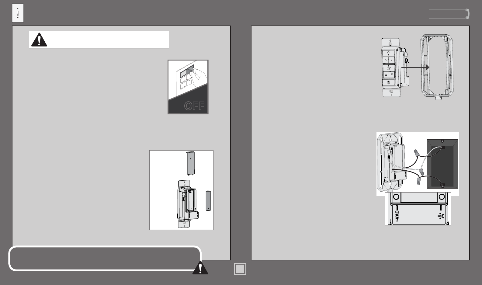
Turning off the power
1
Ensure the power is OFF at the outlet
box and wall switch location before
proceeding with installation.
Turn Power
OFF
Installing the baery
2
To access the baery compartment,
slide the baery door up.
Replace the used baery with two AAA
baeries when needed.
This device complies with Part 15 of the FCC Rules. Operation is subject to the following
conditions: (1) this device may not cause harmful interference, and (2) this device must accept
any interference received, including interference that may cause undesired operation.
Battery
Door
M8552-01 • 03/04/19 • © 2019 Casablanca Fan Company
14
Installing the Wall Plate Bracket
3
Snap the Wall Control into the
Wall Plate Bracket.
Wiring the Wall Control
4
1. Connect the grounding wire
from the wall control to the
ground control from the switch
box using the provided wire
nuts.
2. Connect the “LIVE IN” from
the switch box to the “~VAC”
from the wall control using the
provided wire nuts.
3. Connect the “LIVE OUT” from
the switch box to the “FAN” out
from the wall control using the
provided wire nuts.
4. Push all wires into the switch
box.
www.CasablancaFanCo.com
1.888.227.2178

Wall Control For Single Switch
www.CasablancaFanCo.com
1.888.227.2178
Installing the Wall Control
5
Install the longer screws
through the slots in the wall
control into the switch box
screw holes.
Installing the Wall Plate
6
Push the wall plate onto the
Wall Plate Bracket. It should
snap into place.
Turning on the power
7
IMPORTANT
Reference the included remote function card
8
for information on how to use your wall control!
Turn Power
ON
15
M8552-01 • 03/04/19 • © 2019 Casablanca Fan Company

Wall Control For Dual Switches
www.CasablancaFanCo.com
1.888.227.2178
To install the Casablanca Wall Control into a dual switch location,
you will need a wall plate with both a standard switch and rocker
switch cut-out (sold separately).
If you are unfamiliar or
uncomfortable with wiring, please
contact a qualified electrician.
(Sold Separately)
Installing the baery
1
To access the baery compartment,
slide the baery door up.
Replace the used baery with two AAA
baeries when needed.
Battery
Door
Verify which switch controls the fan light.
2
1. Turn on power for the fan.
2. Push both existing wall switches to
the on position.
3. Press the Fan and Light buon on
the Casablanca Wall Control.
4. Your fan’s light and fan should be
on.
5. Push each of your existing wall
switches into the off position one at
a time to determine which switch
controls the Light.
6. The Light switch will not be
replaced when installing the
Casablanca Wall Control. You may
find it helpful to mark the Light
switch with a pencil or some other
non-permanent mark.
IMPORTANT
Turn off the power
3
Ensure the power is OFF at the outlet
box and wall switch location before
proceeding with installation.
Turn Power
ON
Turn Power
OFF
16
M8552-01 • 03/04/19 • © 2019 Casablanca Fan Company

Wall Control For Dual Switches
www.CasablancaFanCo.com
1.888.227.2178
Remove the existing wall plate
4
Remove the existing wall plate.
Save the screws. You will need
them for the existing, marked
light switch.
Remove the Casablanca Wall
5
Control frame.
Remove the frame from the
Casablanca Wall Control. You
will not need it for the dual
switch installation process.
Wiring the Casablanca Wall
6
Control
1. Connect the grounding wire
from the wall control to the
ground control from the switch
box using the provided wire
nuts.
2. Connect the “LIVE IN” from
the switch box to the “~VAC”
from the wall control using the
provided wire nuts.
3. Connect the “LIVE OUT” from
the switch box to the “FAN” out
from the wall control using the
provided wire nuts.
4. Push all wires into the switch
box.
Install the Wall Plate
7
Install the wall plate that fits
your setup (sold separately).
1. Use the screws you saved to
reinstall into the light switch.
2. Use the screws included
Installation complete
8
The existing light switch still
controls the light on/off.
Turn on the power
9
IMPORTANT
10
Reference the included remote function card
for information on how to use your wall control!
Turn Power
ON
17
M8552-01 • 03/04/19 • © 2019 Casablanca Fan Company
Wall Control
www.CasablancaFanCo.com
1.888.227.2178
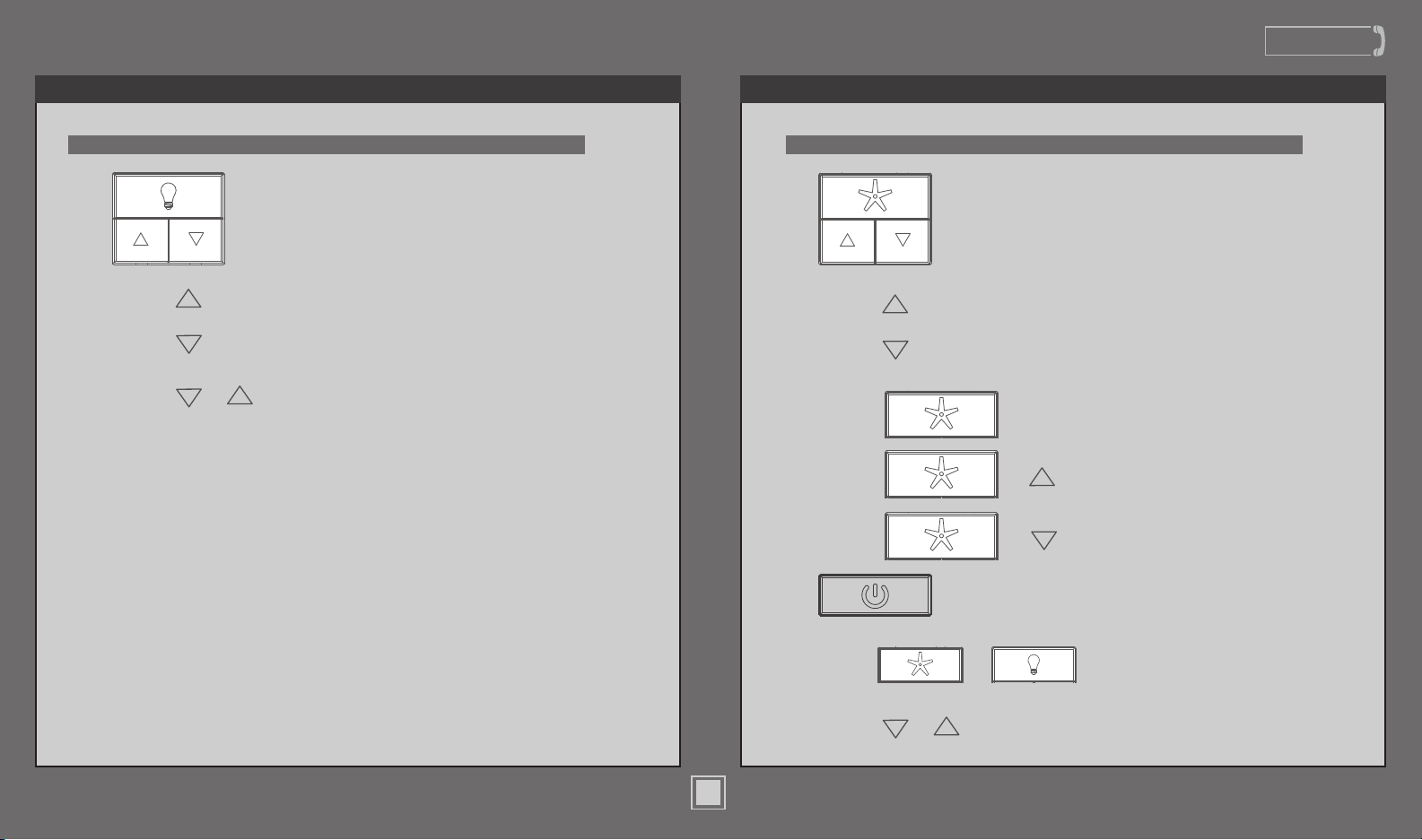
KEYPRESS KEYPRESS
LIGHTFUNCTIONS FANFUNCTIONS
FUNCTION FUNCTION
Light On/Off
Light Dimming
Control
Long
Press
Long
Press
Long
Press
+
Light High
Light Low
Dimming Mode
On/Off
Long
Press
Long
Press
Long
Press
Long
Press
Long
Press
+
+
Fan On/Off
Fan Speed
Control
Fan High
Fan Low
Fan Reverse
Fan Updraft
Fan Downdraft
Power On/Off
Long
Press
Long
Press
18
M8552-01 • 03/04/19 • © 2019 Casablanca Fan Company
+
+
Pair Function
Reset
(For WiFi enabled fans ONLY)

Maintenance & Cleaning
Turn Power
OFF
Be sure to turn off
power to the fan
before performing
any maintenance.
www.CasablancaFanCo.com
1.888.227.2178
Cleaning the fan - use soft brushes or cloths
to prevent scratching. Cleaning products may
19
M8552-01 • 03/04/19 • © 2019 Casablanca Fan Company
damage the nishes.

Troubleshooting
www.CasablancaFanCo.com
1.888.227.2178
Fan doesn’t work
• Press a fan speed button (up or
down arrow.
• Check the circuit breaker to
ensure the power is turned on.
• Check the wall control battery.
• Make sure the blades spin freely.
• Turn off power from the circuit
breaker, then loosen the canopy
and check all the connections
according to the wiring diagram.
Fan keeps spinning after power
is turned off
• The blades may take a few
minutes to come to a complete
stop. The powerful Casablanca
motor combined with the
unique blade design on this fan
allows for great air movement,
but this may cause the blades
to keep spinning for longer
than expected after power is
turned off.
Remote does not work
• Make sure the battery is installed
correctly.
• Install a new battery.
• If the remote still does not
work, you may need to pair
your remote. To prevent faulty
operation, please disconnect
power (at the wall switch,
breaker, or fan) from all other
ceiling fans within range while
pairing. To pair: cycle power
to the fan by turning power off
and back on at the wall switch
(or circuit breaker if necessary).
Within three minutes, press and
hold both the Fan and Light
button for four seconds to pair
the remote. If applicable, the
fan will turn on and the lights
will ash and stay on to indicate
successful pairing.
LED lights will not dim
• To enable dimming, you
must rst set your remote to
Dimming Mode. To toggle
Dimming Mode on or off, long
press the up and down button
together.
AUTHORIZED SERVICE
CENTERS
For the most updated list of
Casablanca Authorized Service
Centers, visit
www.CasablancaFanCo.com or
call toll free 1-888-227-2178.
20
M8552-01 • 03/04/19 • © 2019 Casablanca Fan Company

Troubleshooting (continued)
www.CasablancaFanCo.com
1.888.227.2178
Installing Multiple Fans with Independently Operating Remote Controls
To install multiple fans with independently operating remote controls, there is no need to
perform any pairing procedures. Each set of receiver/transmitter is already paired. Simply
install each receiver into a fan and use the appropriate transmitter to operate each fan.
If your remote is not working, see the “Remote does not work” section on the previous page.
Installing Multiple Fans Operating on a Single Remote Control
To have multiple fans operated by a single remote control, you must pair the transmitter to each
additional receiver. The receiver that shipped with your fan is already paired to the transmitter.
Note: To prevent faulty operation, you MUST disconnect power (at the wall switch,
breaker, or fan) from all other ceiling fans within range while pairing each fan.
For each additional fan, ensure that a compatible receiver is installed. Disconnect power from all
other fans while pairing. To pair: cycle power to the fan by turning power off and back on at
the wall switch (or circuit breaker if necessary). Within three minutes, press and hold both
the Fan and Light button for four seconds to pair/unpair the remote. If applicable, the fan
will turn on and the lights will ash and stay on to indicate successful pairing.
Installing One Fan Operating on Multiple Remote Controls
To have multiple remote controls operate one fan, you must pair each additional transmitter
to the receiver in the fan. The transmitter that shipped with your fan is already paired.
Note: To prevent faulty operation, please disconnect power (at the wall switch,
breaker, or fan) from all other ceiling fans within range while pairing.
For each additional transmitter, cycle power to the fan by turning power off and back on at
the wall switch (or circuit breaker if necessary). Within three minutes, press and hold both
the Fan and Light button for four seconds to pair the remote. If applicable, the fan will
turn on and the lights will ash and stay on to indicate successful pairing.
“Unpairing” Procedure for Faulty Operation of Remote Controls
If a transmitter is mistakenly operating a fan, you need to “unpair” the transmitter from that
fan’s receiver. The “unpairing” procedure is the same as the pairing procedure.
Note: To prevent faulty operation, you MUST disconnect power (at the wall switch,
breaker, or fan) from all other ceiling fans within range while “unpairing” a fan.
Disconnect power from all other fans while “unpairing.” Then, cycle power to the fan you
wish to “unpair” by turning power off and back on at the wall switch (or circuit breaker if
necessary). Within three minutes, press and hold both the Fan and Light button button
for four seconds to “unpair” the remote. If applicable, the fan will turn off and the lights
will ash and turn off to indicate successful “unpairing.”
21
M8552-01 • 03/04/19 • © 2019 Casablanca Fan Company
 Loading...