

Page 1
www.CasablancaFanCo.com
1.888.227.2178
1
M8509-01 • 06/24/13 • © Casablanca Fan Company
PAG E
17
Maintenance
& Cleaning
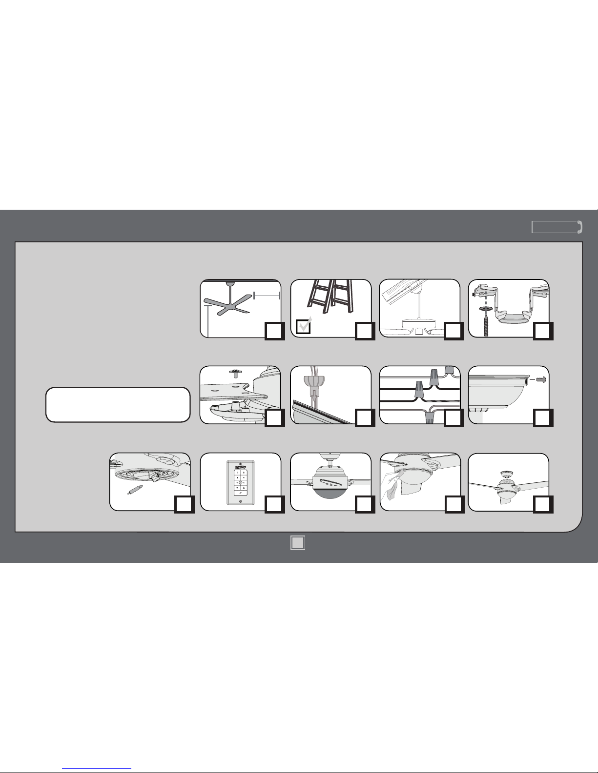
Table of Contents
PAG E
5
30 inches
7 feet
PAG E
2
What to Expect with
Your Installation
Ceiling Bracket
Ladder
PAG E
3
Tools Needed
PAG E
7
PAG E
10
Wiring CanopyDownrod
PAG E
12
PAG E
4
Mounting Options
PAG E
6
Blades
Congratulations on purchasing your new
Casablanca® ceiling fan! It will provide
comfort and performance in your home
or ofce for many years. This installation
and operation manual contains complete
instructions for installing and operating
your fan.
We are proud of our work and appreciate
the opportunity to supply you with the
best ceiling fan available anywhere in the
world.
To register your fan, please visit:
www.CasablancaFanCo.com/register
Save your receipt for proof of purchase.
Troubleshooting
?
?
?
PAG E
18
PAG E
13
Light Kit
PAG E
14
Operation
PAG E
16
Optional Bottom Cap
Page 2
www.CasablancaFanCo.com
1.888.227.2178
2
M8509-01 • 06/24/13 • © Casablanca Fan Company
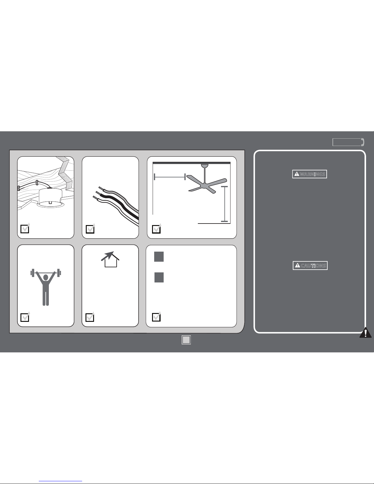
What to Expect with Your Installation
Know your wiring
If you are unfamiliar
with wiring, use a
qualied electrician.
You may need a
friend to help you.
Check box to see
fan weight
Assess location
30 inches
from blade tip to
nearest wall or
obstruction
7 feet
from bottom
edge of blade
to the oor
Select a downrod length
Assess ceiling angle
Must be able to
secure the fan to
building structure or
fan-rated outlet box
1
2
Standard Downrod
for ceilings 8-10 feet high
Longer Downrod
for ceilings 10 feet or higher
Ceiling angles greater
than 34° will require an
Angled Mounting Kit.
See page 4 for details.
w.1 - To reduce the risk of re, electrical shock, or personal
injury, mount fan directly from building structure and/or an
outlet box marked acceptable for fan support of 70 lbs (31.8 kg)
and use the mounting screws provided with the outlet box.
w.2 - To avoid possible electrical shock, before installing or
servicing your fan, disconnect the power by turning off the
circuit breakers to the outlet box and associated wall switch
location. If you cannot lock the circuit breakers in the off
position, securely fasten a prominent warning device, such as a
tag, to the service panel.
w.3 - To reduce the risk of re, electrical shock, or motor damage,
use only Casablanca Solid State Speed Controls.
w.4 - To reduce the risk of personal injury, do not bend the blade
brackets when installing the blade brackets, balancing the blades,
or cleaning the fan. Do not insert foreign objects in between
rotating fan blades.
c.1 - All wiring must be in accordance with national and local
electrical codes ANSI/NFPA 70. If you are unfamiliar with wiring,
use a qualied electrician.
c.2 - Use only Casablanca replacement parts.
This equipment has been tested and found to comply with the
limits for a Class B digital device, pursuant to part 15 of the FCC
Rules. These limits are to provide reasonable protection against
harmful interference in a residential installation. This equipment
generates, uses and can radiate radio frequency energy and if not
installed and used in accordance with the instructions may cause
harmful interference to radio communications.
Read and Save These Instructions
This product conforms to UL Standard 507.
WARNINGS
CAUTIONS
Page 3
www.CasablancaFanCo.com
1.888.227.2178
3
M8509-01 • 06/24/13 • © Casablanca Fan Company
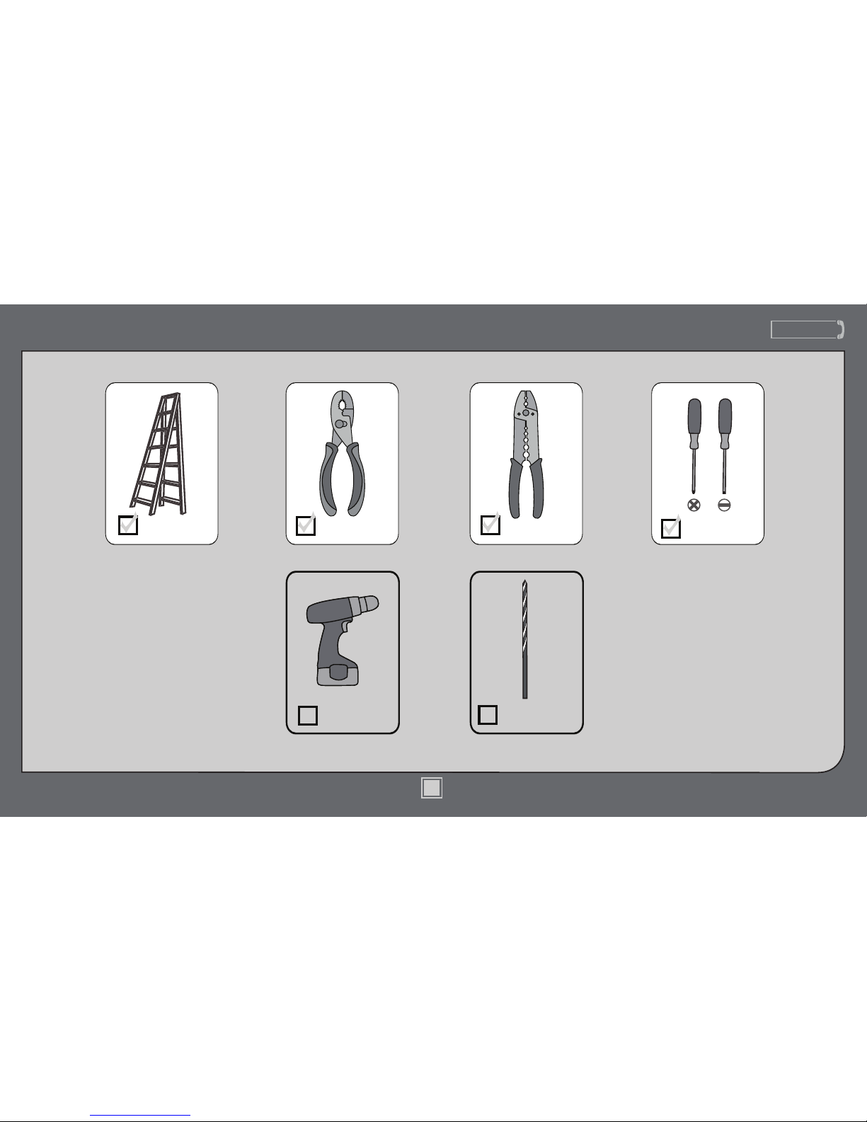
Tools Needed
Ladder
Power Drill
(optional)
9/64” Drill Bit
(optional)
Screwdrivers
Pliers Wire Strippers
If mounting to a support structure, you will also need these tools.
Page 4
www.CasablancaFanCo.com
1.888.227.2178
4
M8509-01 • 06/24/13 • © Casablanca Fan Company
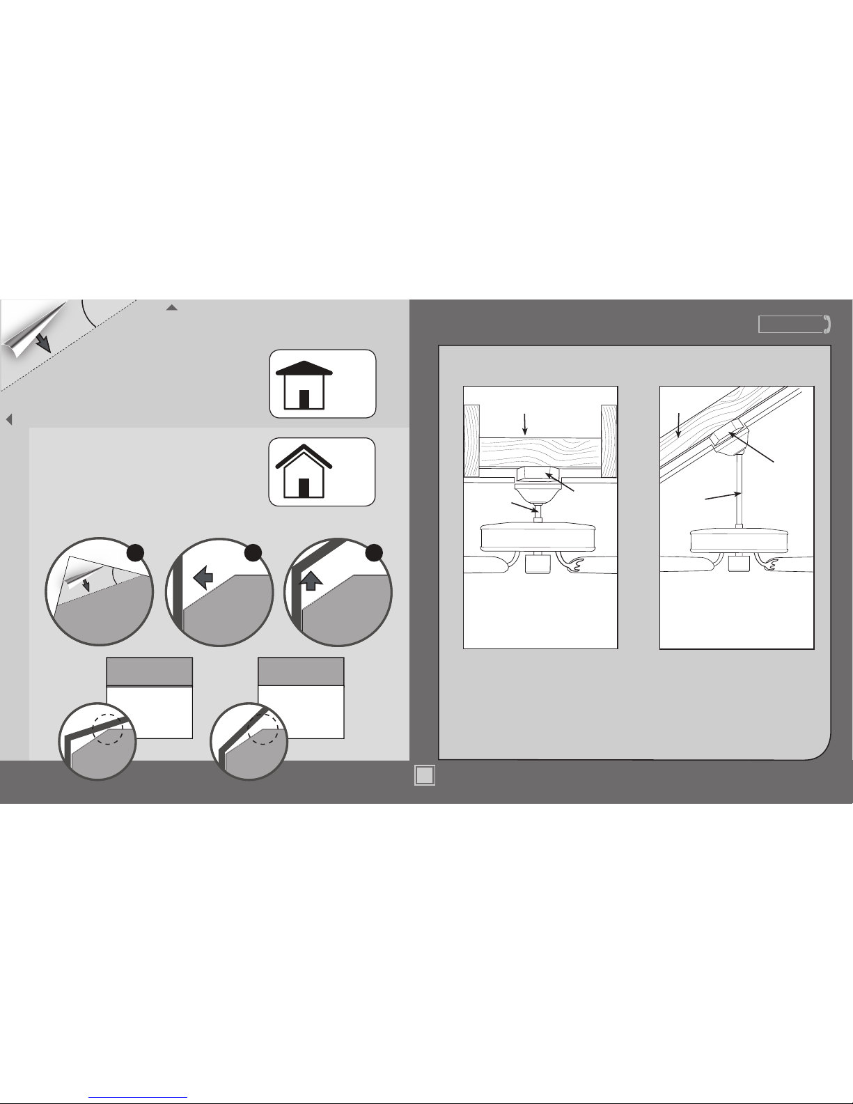
If you have an angled ceiling:
1. You will need a longer downrod (sold separately).
2. If your ceiling angle is greater than 34°, you will
also need an Angled Mounting Kit (sold separately).
Guide Touches
BOTH Ceiling & Wall
S
I
T
U
A
T
I
O
N
1
Guide Touches
Wall
but NOT Ceiling
S
I
T
U
A
T
I
O
N
2
You need BOTH
a Longer
Downrod &
an Angled
Mounting Kit
You need ONLY
a Longer
Downrod
*most common
If you have a at ceiling:
Hang your fan by a standard downrod (included).
Mounting Options
Support
Structure
Ceiling
Outlet Box
(required)
Angled
Mounting
Style
Standard
Mounting
Style
Support
Structure
Ceiling
Outlet Box
(required)
Use Standard Mounting
to hang the fan
from a at ceiling.
Use Angled Mounting
to hang the fan from a
vaulted or angled ceiling.
4
34
O
CEILING
WALL
OPTION
1
Standard
Mounting
OPTION
2
Angled
Mounting
2 3
SLIDE
toward ceiling
PLACE
against wall
1
FOLD
on dotted line
34°
Use the three steps below to determine if your ceiling angle is greater than 34°
1.888.227.2178
M8509-01 • 06/24/13 • © Casablanca Fan Company
Page 5
www.CasablancaFanCo.com
1.888.227.2178
5
M8509-01 • 06/24/13 • © Casablanca Fan Company
1.888.227.2178
www.CasablancaFanCo.com
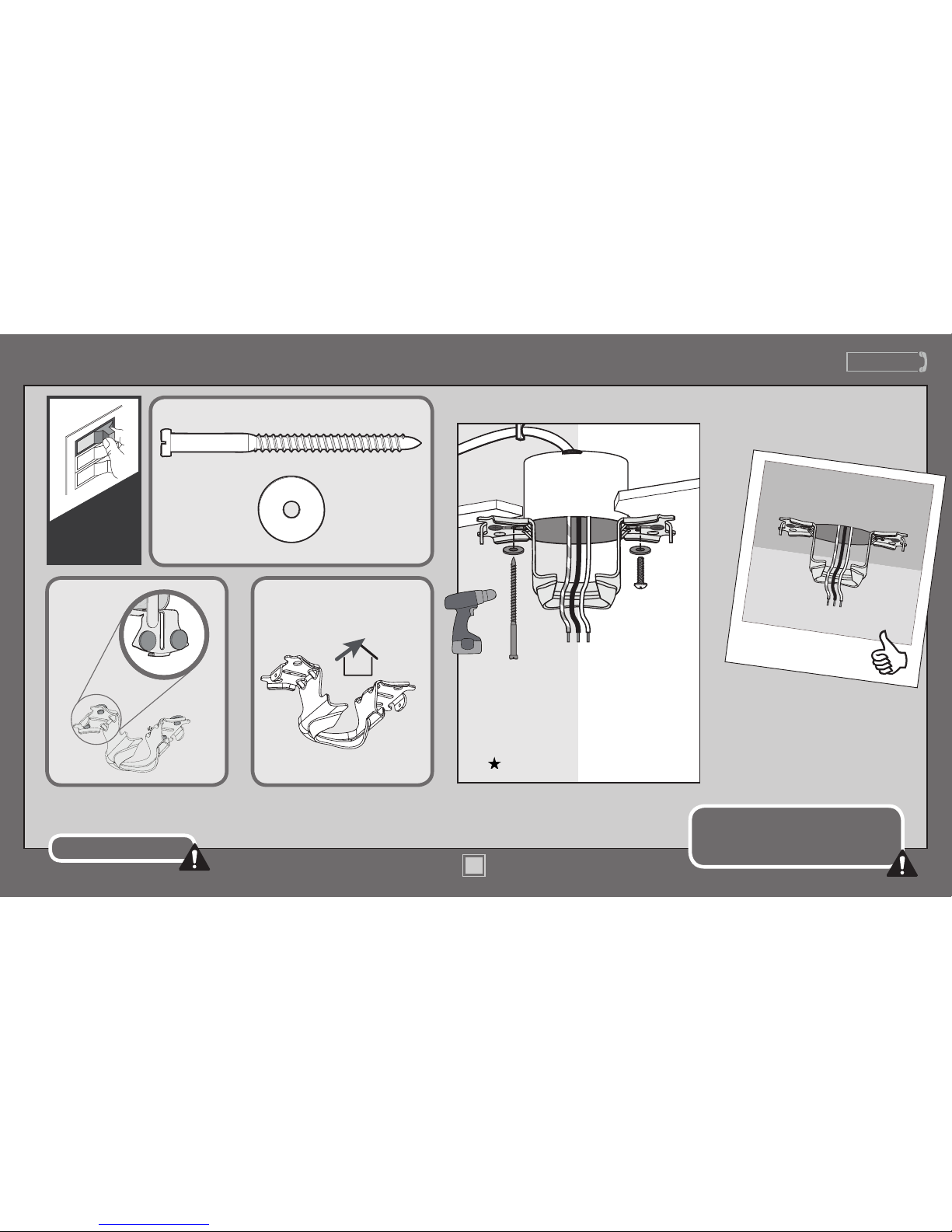
Ceiling Bracket
Refer to warning w.1 on pg. 2
To avoid possible electrical shock, before
installing your fan, disconnect the power by
turning off the circuit breakers to the outlet
box associated with the wall switch location.
For angled ceilings, point
opening toward peak.
If you are unable to do this,
call Technical Support at
1-888-227-2178.
Make sure all four bumpers are
still attached.
Use wood screws
(included) when securing
to support structure with
approved electrical outlet
box. Drill 9/64” pilot holes
in support structure to aid
in securing ceiling bracket
with hardware found in
the hardware bag.
Use machine screws
(provided with outlet
box) when securing to
existing ceiling fan-rated
outlet box. Make sure
it is securely installed
and is acceptable for fan
support of 31.8 kg (70 lbs)
or less.
OFF
Turn Power
Page 6
www.CasablancaFanCo.com
1.888.227.2178
6
M8509-01 • 06/24/13 • © Casablanca Fan Company
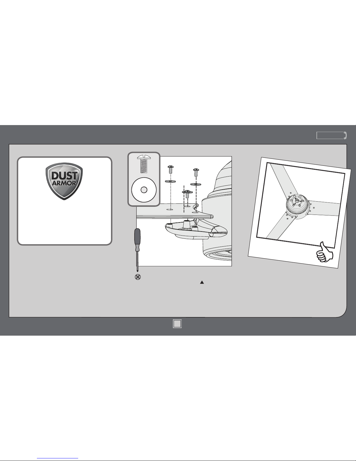
Blades
Attach each blade to the motor housing
using three blade screws and three
blade washers, found in the hardware
bag. Securely tighten after all three
screws are attached.
Note: The sticker on the blade should
be facing downward.
Your blades are shielded with Dust
Armor® which is a nanotechnology
coating that repels dust. For cleaning
the fan, use soft brushes or cloths to
prevent scratching. Cleaning agents
may damage the nishes.
Page 7
www.CasablancaFanCo.com
1.888.227.2178
7
M8509-01 • 06/24/13 • © Casablanca Fan Company
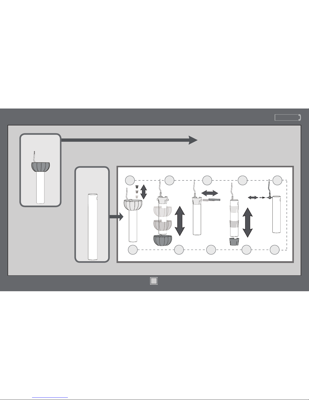
Slide
Slide
1 2 3 4 5
678910
Sold Separately
Longer
Downrod
for angled
ceilings or
ceilings 10’ or
higher
Standard
Downrod
for ceilings 8-10’ high
Option 1
Option 2
skip to next page
If you need a different downrod length follow these steps:
Steps 1-5 to remove standard downrod pipe
Steps 6-10 to reassemble with new pipe
Included
(pre-assembled)
Downrod
Page 8
www.CasablancaFanCo.com
1.888.227.2178
8
M8509-01 • 06/24/13 • © Casablanca Fan Company
Downrod (continued)
KEEP!
8”
3/8”
C
U
T
&
S
T
R
I
P
(not to scale)
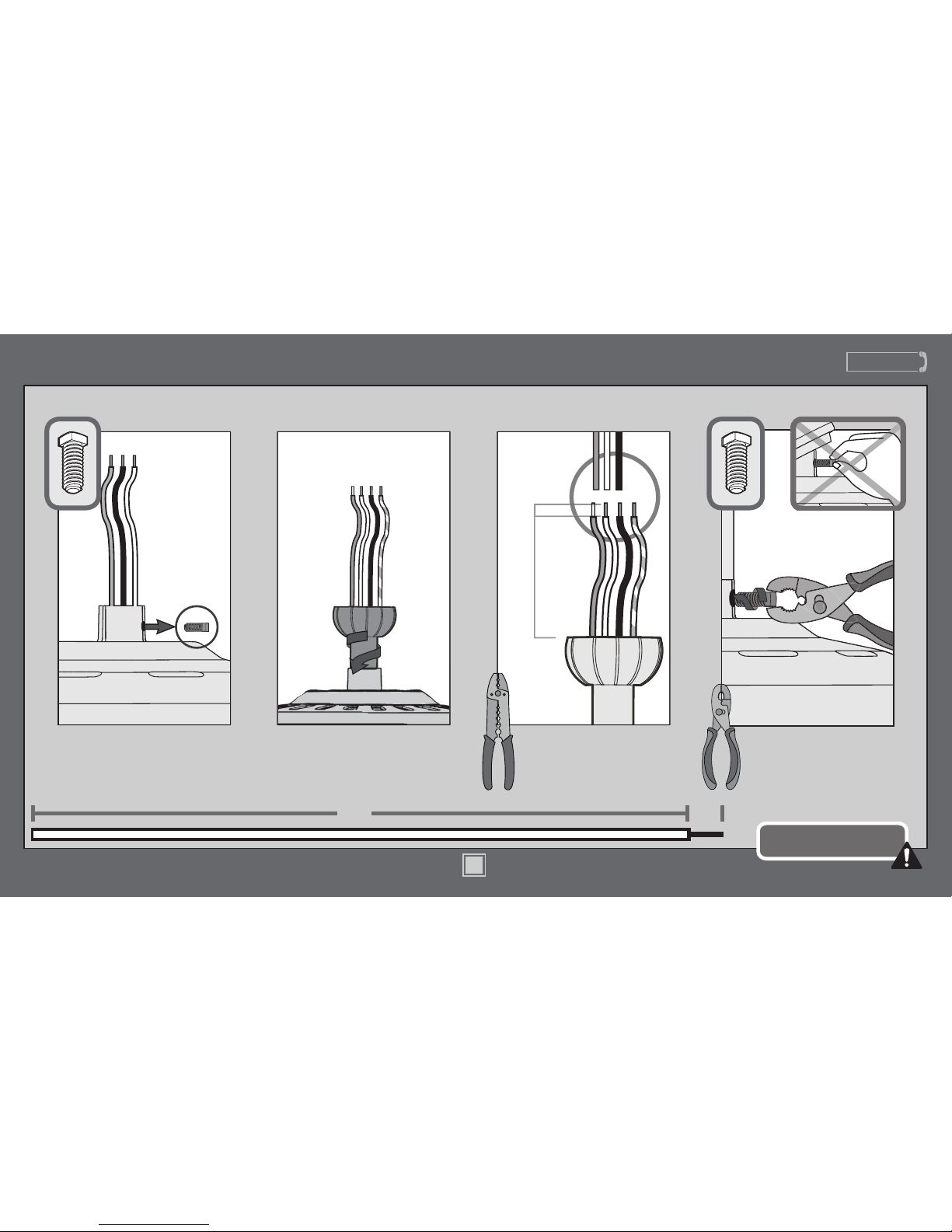
Remove the pre-installed
setscrew so that the downrod
can be inserted.
Hand tighten the downrod (at
least 4-5 full turns) until it stops.
The wires can be cut, but
leave at least 8” extending
from the top of the downrod.
8”
3/8”
Tighten the setscrew
with pliers. DO NOT
HAND TIGHTEN.
If the setscrew is not tightened
securely, the fan may fall.
K
E
E
P
!
Page 9
www.CasablancaFanCo.com
1.888.227.2178
9
M8509-01 • 06/24/13 • © Casablanca Fan Company
Downrod (continued)
1.888.227.2178
9
www.CasablancaFanCo.com
M8509-01 • 06/24/13 • © Casablanca Fan Company
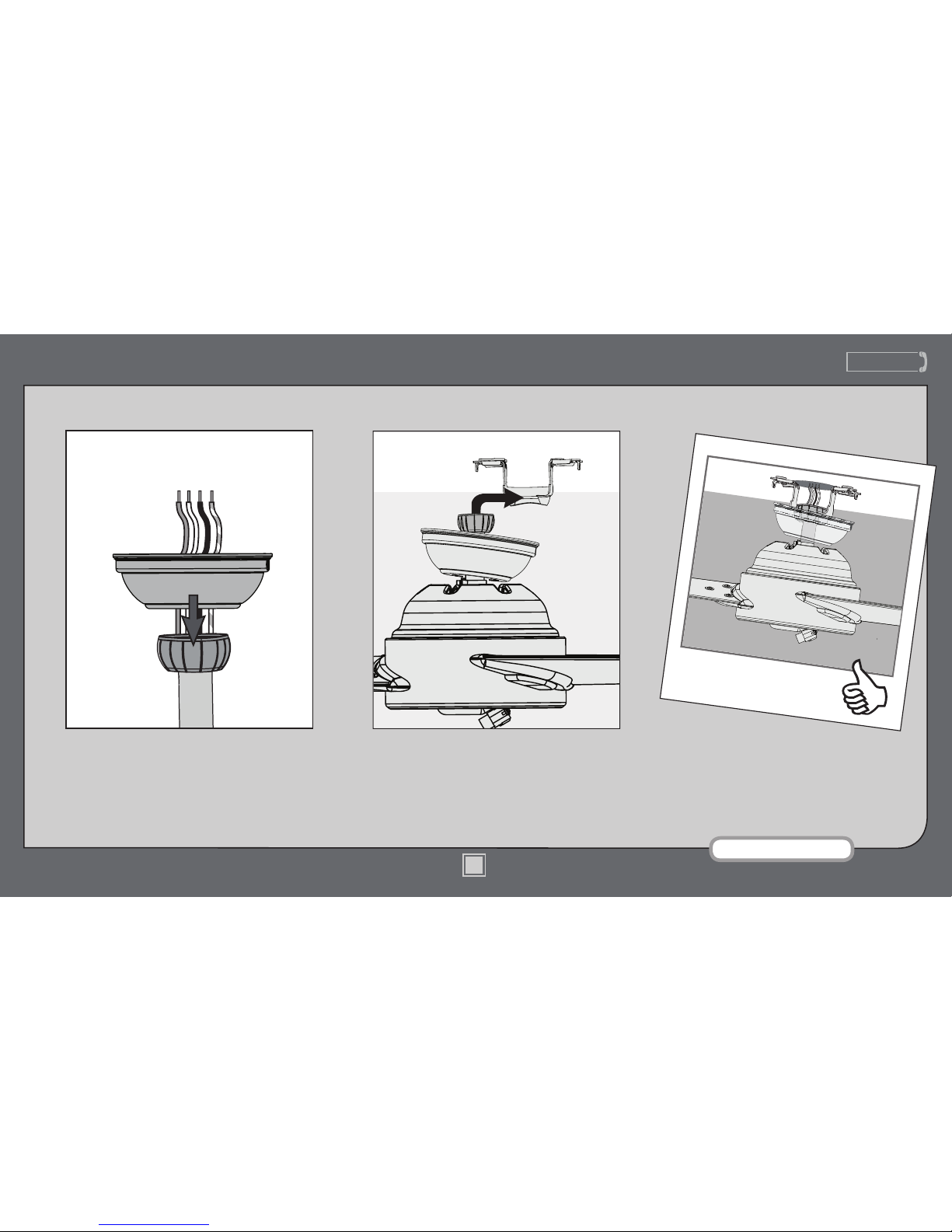
DO NOT PICK THE FAN UP BY THE
CANOPY OR WIRES. Place the downrod
ball into the slot in the ceiling bracket.
Put the wires and downrod through the canopy.
Let the canopy sit loosely on top of the fan.
Note: Fan style may vary.
Page 10

www.CasablancaFanCo.com
1.888.227.2178
10
M8509-01 • 06/24/13 • © Casablanca Fan Company
Wiring
Turn the splices upward and push them carefully back through the hanger bracket
into the outlet box. Spread the wires apart, with the grounded wires on one side of
the outlet box and the ungrounded wires on the other side of the outlet box.
Refer to CAUTION c.1 on pg. 2
F
R
O
M
R
E
C
E
I
V
E
R
F
R
O
M
C
E
I
L
I
N
G
F
R
O
M
C
E
I
L
I
N
G
B
R
A
C
K
E
T
Using an orange wire
connector from
the hardware bag,
connect the 3 grounding
wires (green, green/
yellow stripe, or bare
copper) coming from the
ceiling, downrod, and
hanging bracket.
green/yellow stripe
(grounding)
green/yellow stripe
green/yellow stripe
white
black
blue
white (common out)
black (fan out)
blue (light out)
Note: To connect the wires,
hold the bare metal leads
together and place a wire
connector over them, then twist
clockwise until tight.
Using the blue wire
connectors from the remote
control hardware bag,
connect the white wire
from the receiver (marked
“common out”) to the white
wire from fan. Connect the
black wire from the receiver
(marked “fan out”) to the
black wire from the fan.
Connect the blue wire from
the receiver (marked ”light
out”) to the blue wire from
the fan. The red wire from
the receiver will not be used,
it has a pre-installed wire
terminator.
F
R
O
M
F
A
N
F
R
O
M
F
A
N
F
R
O
M
R
E
C
E
I
V
E
R
Using an orange wire
connector from
the hardware bag,
connect the black wire
(ungrounded) from the
ceiling to the black wire
from the receiver (marked
“live in”). Connect the
white wire (grounded)
from the ceiling to
the white wire from
the receiver (marked
“neutral in” or
“common in”).
F
R
O
M
C
E
I
L
I
N
G
black (ungrounded)
white (grounded) white (neutral in)
black (live in)
Page 11
www.CasablancaFanCo.com
1.888.227.2178
11
M8509-01 • 06/24/13 • © Casablanca Fan Company
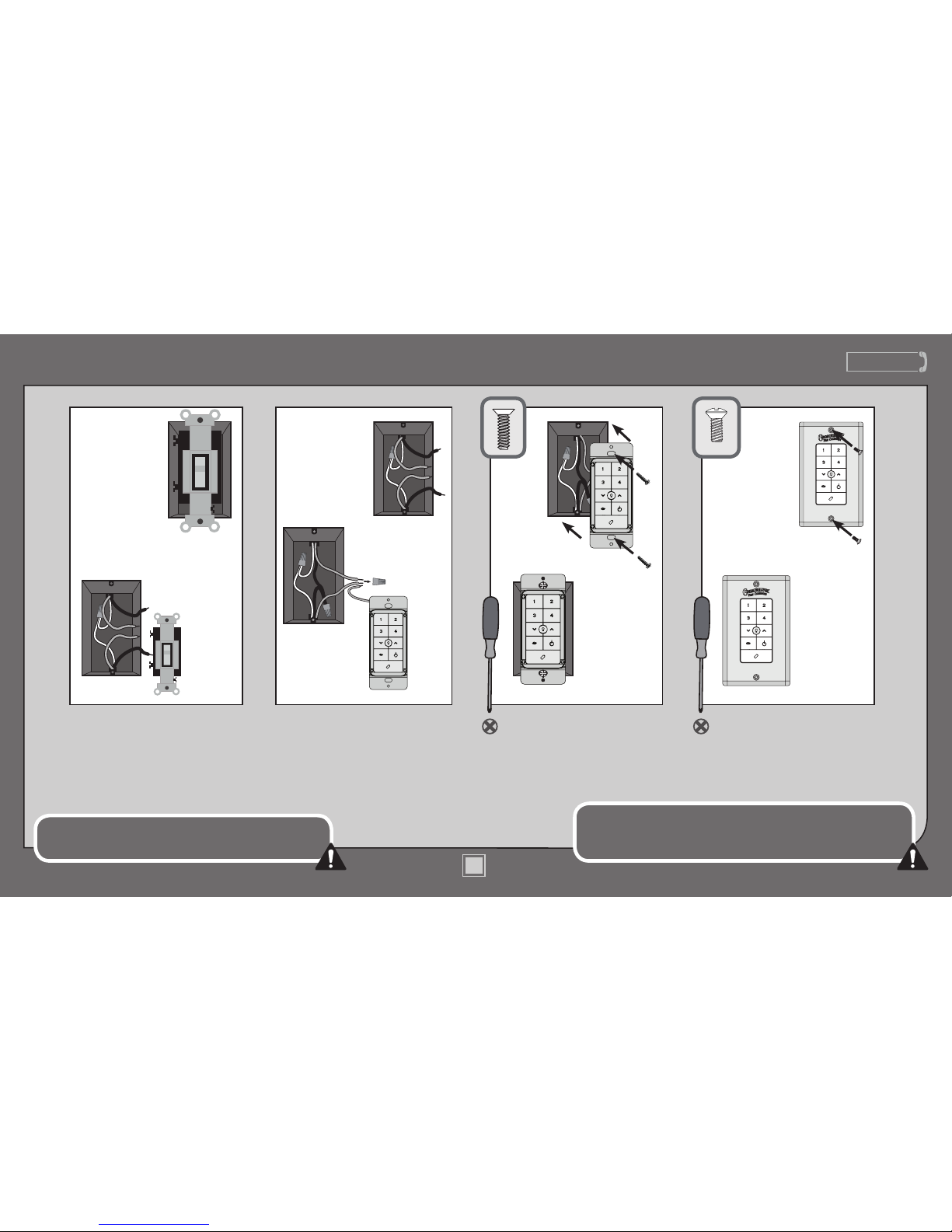
Using orange wire connectors,
connect the two black wires
(ungrounded) from the outlet
box. Also connect the two green
or bare wires (grounding) from
the outlet box with the grounding
wire from the wall control.
After removing the switch plate
cover, remove all wiring from
the switch.
Insert the wall control into
the outlet box and secure the
two screws using a Phillips
head screwdriver.
Install the cover plate using a
Phillips Head screwdriver to
secure the two cover plate screws.
Wiring (continued)
Push all connections to the back of the switch box. Spread the
wires apart, with the grounded wires on one side of the switch box
and the ungrounded wires on the other side of the switch box.
This device complies with Part 15 of the FCC Rules. Operation is subject to
the following conditions: (1) this device may not cause harmful interference,
and (2) this device must accept any interference received, including
interference that may cause undesired operation.
Before
BeforeBefore
Before
After After After After
Page 12
www.CasablancaFanCo.com
1.888.227.2178
12
M8509-01 • 06/24/13 • © Casablanca Fan Company
Canopy
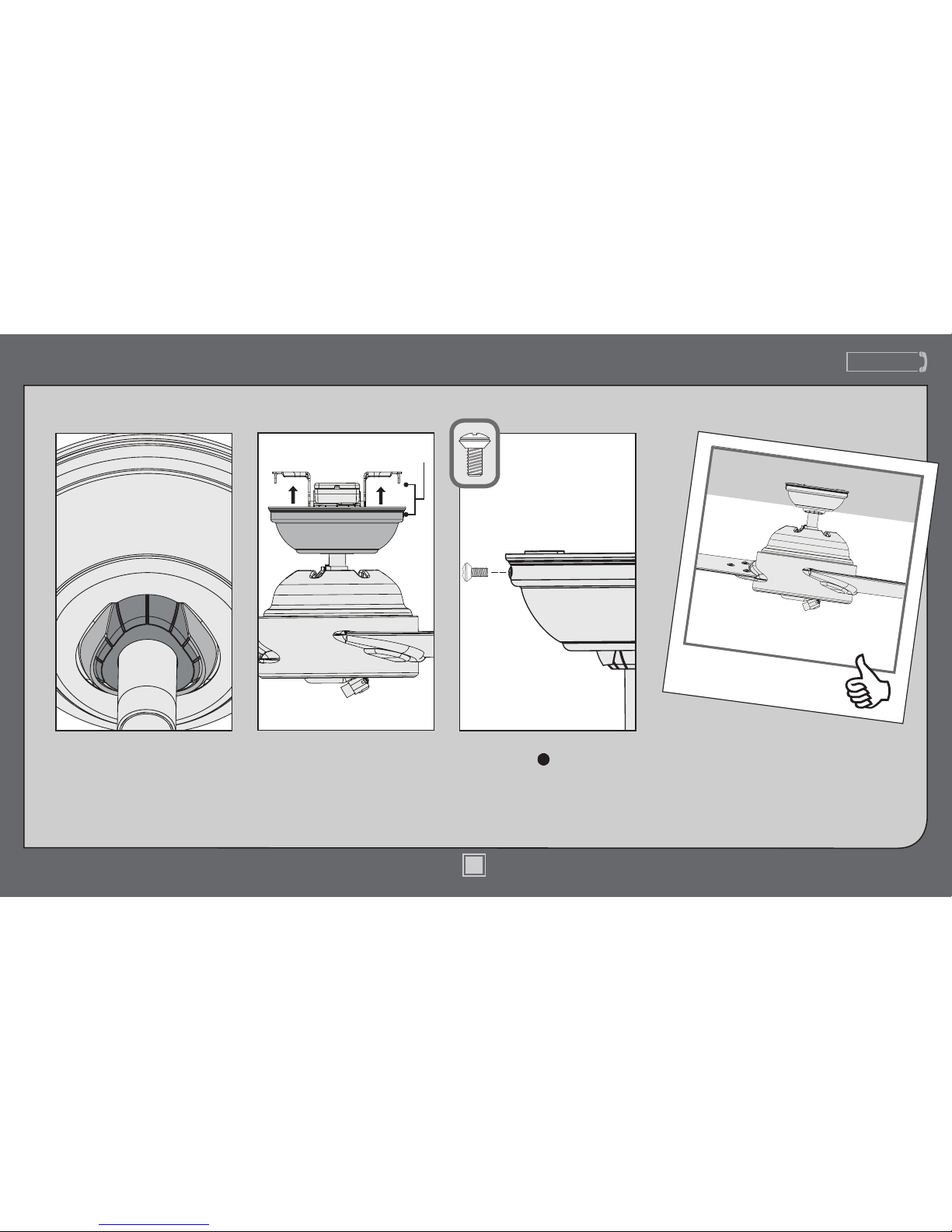
Lift the canopy into place so that
the screw holes are aligned.
Position the canopy so that, when
lifted into place, the canopy ts into
the hanging bracket as shown.
Screw
Holes
Insert the two canopy screws
found in the hardware bag.
Page 13
www.CasablancaFanCo.com
1.888.227.2178
13
M8509-01 • 06/24/13 • © Casablanca Fan Company
Light Kit
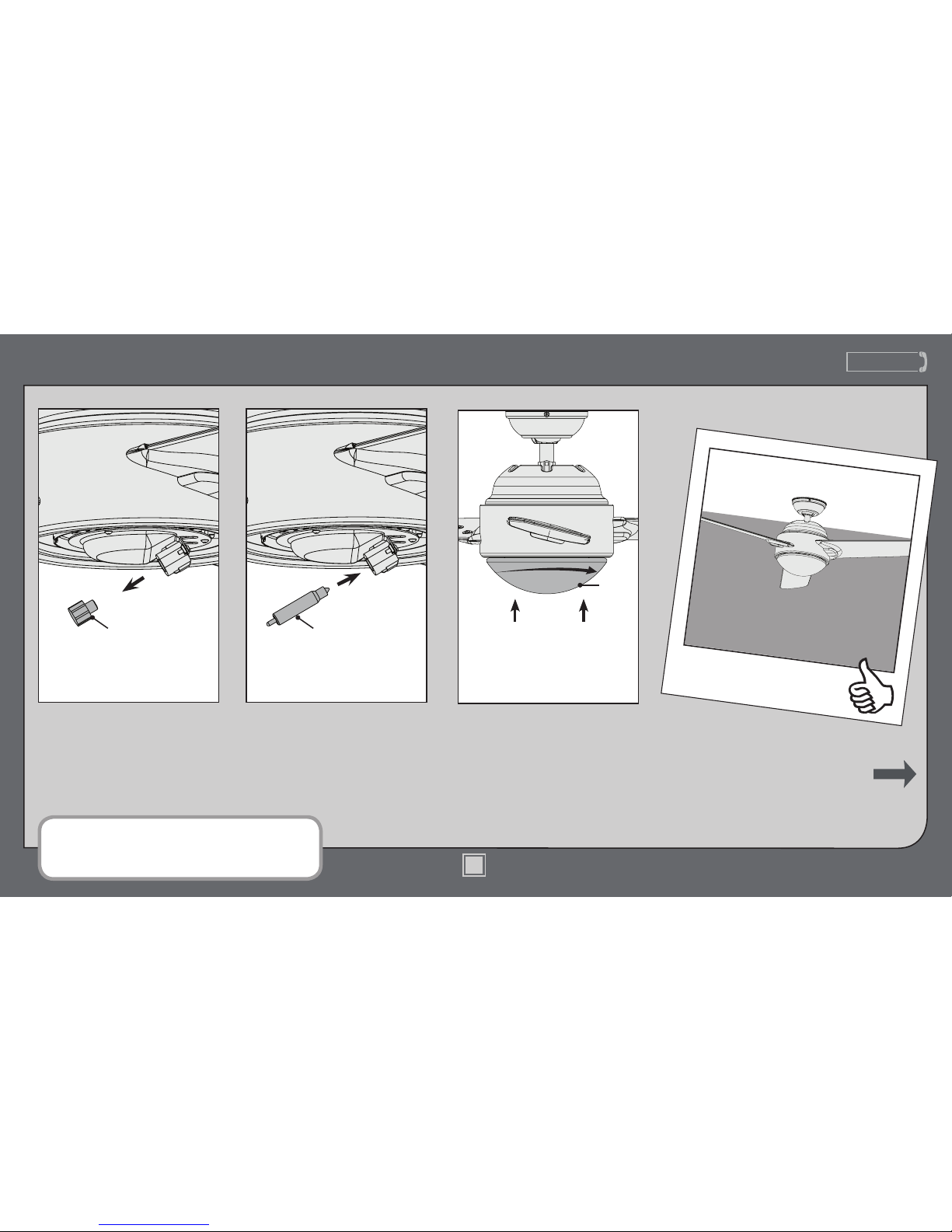
Position the indentations in the
outer rim of the globe so they line
up with the tabs on the inside of
the fan light kit. Carefully lift the
globe up inside the light kit as far
as it will go, then rotate the globe
clockwise until it is held tightly in
place by the three tabs.
Install a halogen bulb in the
socket. When necessary, replace
with bulbs of the same type
and wattage.
CONGRATULATIONS!
YOU’RE DONE!
See next page for fan
operation instructions.
Globe
Remove the socket plug from the
light bulb socket and put aside for
safe-keeping. If you ever decide
to install the optional bottom cap,
you will need the socket plug.
BulbSocket Plug
Note: In compliance with US federal energy regulations, this ceiling
fan contains a device that restricts its light output. Exceeding the
wattage limit marked on the MAX wattage sticker afxed to the
light socket(s) may result in re hazard or improper operation.
13
Page 14
www.CasablancaFanCo.com
1.888.227.2178
14
M8509-01 • 06/24/13 • © Casablanca Fan Company
14
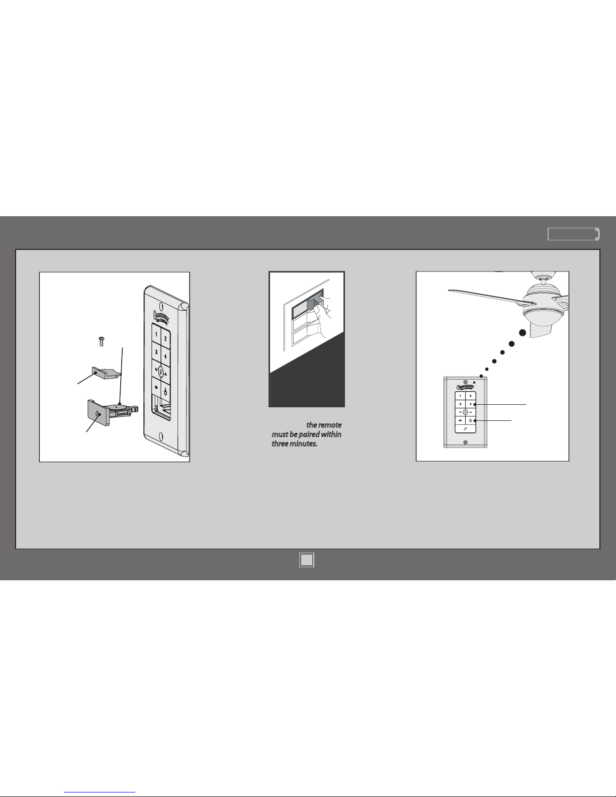
Operation
ON
Turn Power
The fan must be paired before it will
operate. Press the “4” button and the fan
power button simultaneously for at least
three seconds. The fan will turn at the
lowest speed signifying that the remote
pairing process is complete.
Fan
Power
4
Once the power is
turned on, the remote
must be paired within
three minutes. Pairing
is only required
once after initial
installation.
Before operating the wall control, press on the
battery door to eject it. Unscrew the battery
holder. Insert the battery, found in the control
hardware bag, with the positive (+) side facing
downward. Reinstall the battery holder and
reinsert the battery door into the wall control.
Battery
Battery
Holder
Battery
Door
Page 15
www.CasablancaFanCo.com
1.888.227.2178
15
M8509-01 • 06/24/13 • © Casablanca Fan Company
www.CasablancaFanCo.com
1.888.227.2178
15
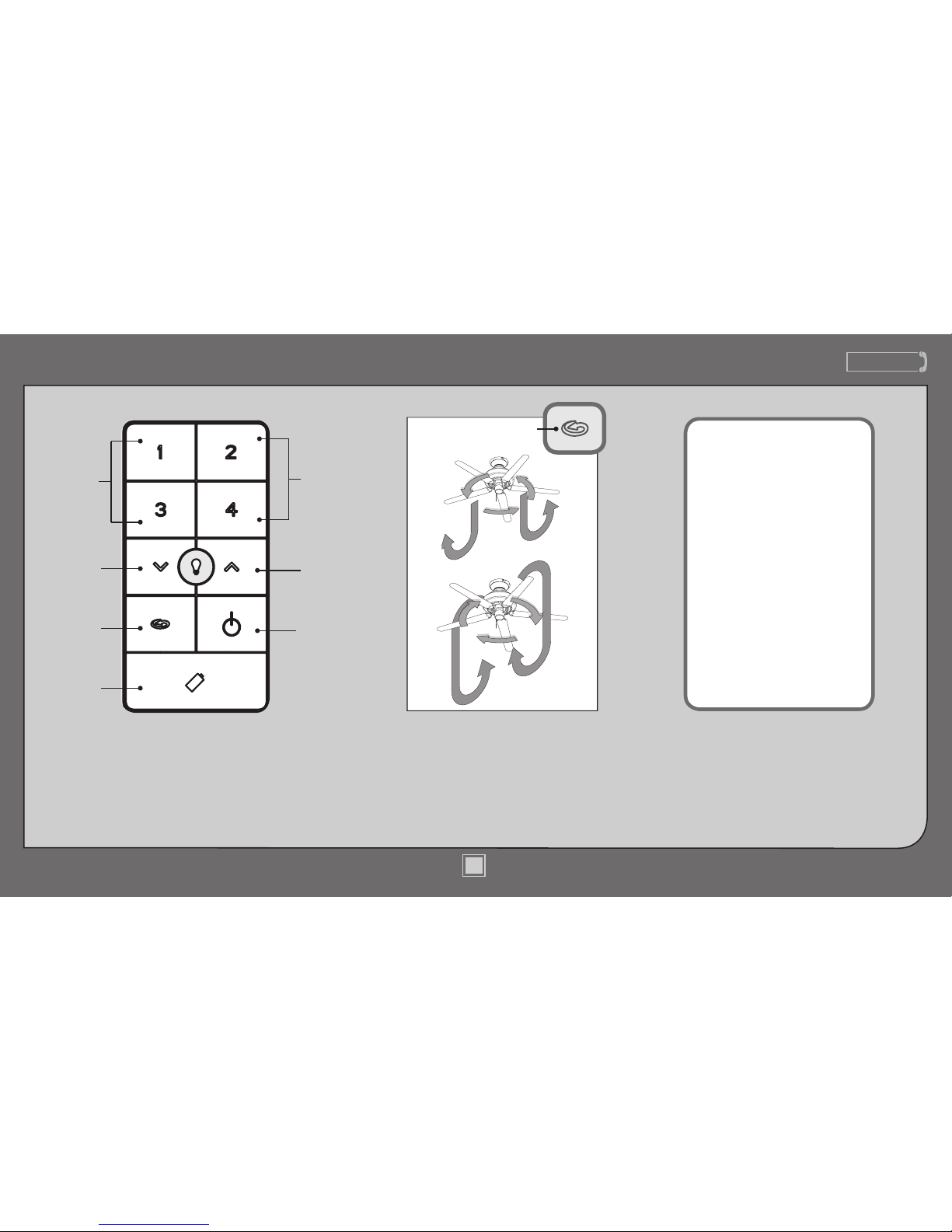
Operation (continued)
Quickly press the up or down arrow
to turn the lights off and on. Hold
the up or down arrow to raise or
dim the light level. The reverse
button changes the direction that
the blades turn. The power button
turns the fan off and on.
Lights
Down
Fan
Speed
Reverse
Battery
Holder
Fan
Power
Lights
Up
Fan
Speed
(Low)
(High)
The reverse button on the wall
control changes the air ow
pattern. In warm weather, use
(a) downward air ow pattern.
In cold weather, use (b) upward
air ow pattern.
(a)
(b)
Reverse
Button
• Press the fan power button
off for at least three seconds to
initiate the Safe-Exit Mode.
• The lights will ash for visual
conrmation.
• The lights will stay on 50%
brightness for 20 seconds and
then begin to dim. After a total
of 30 seconds, the lights will be
completely off.
Note: For CFL lighting, the lights
will stay on 100% brightness
for 30 seconds. After a total of
30 seconds, the lights will be
completely off.
The Safe-Exit Program gives
you about thirty seconds of
light when you turn the lights
off to exit the room before the
lights go out. To use Safe-Exit:
M8509-01 • 06/24/13 • © Casablanca Fan Company
Page 16
www.CasablancaFanCo.com
1.888.227.2178
16
M8509-01 • 06/24/13 • © Casablanca Fan Company
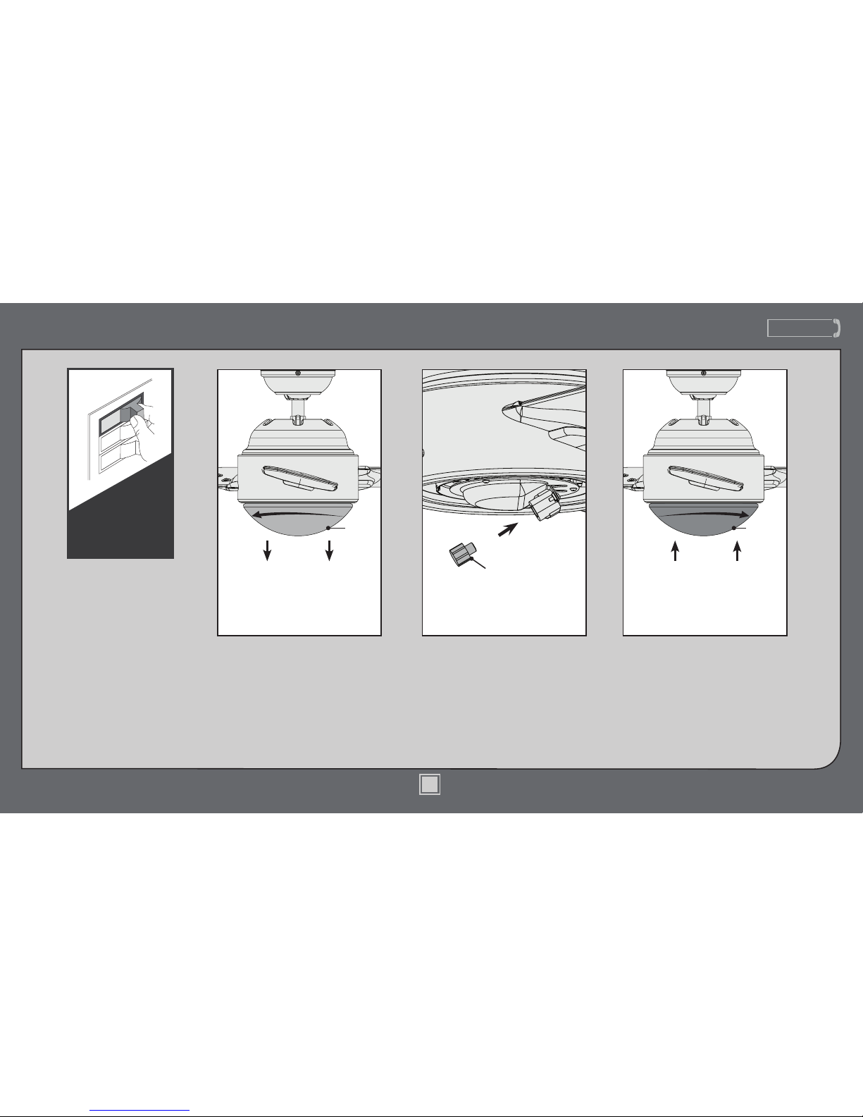
Optional Bottom Cap
Install the socket plug.Carefully rotate the globe
counterclockwise until it comes
loose from the tabs and lower it
from inside the light kit. Remove
the bulb. Put the globe and bulb
aside for safe-keeping.
Position the indentations in the
outer rim of the bottom cap so
they line up with the tabs on
the inside of the fan light kit.
Carefully lift the bottom cap
up inside the light kit as far as
it will go, then rotate the cap
clockwise until it is held tightly
in place by the three tabs.
Be sure to turn off
power to the fan
before installing the
bottom cap.
OFF
Turn Power
Bottom
Cap
Globe
Socket Plug
Page 17
www.CasablancaFanCo.com
1.888.227.2178
17
M8509-01 • 06/24/13 • © Casablanca Fan Company
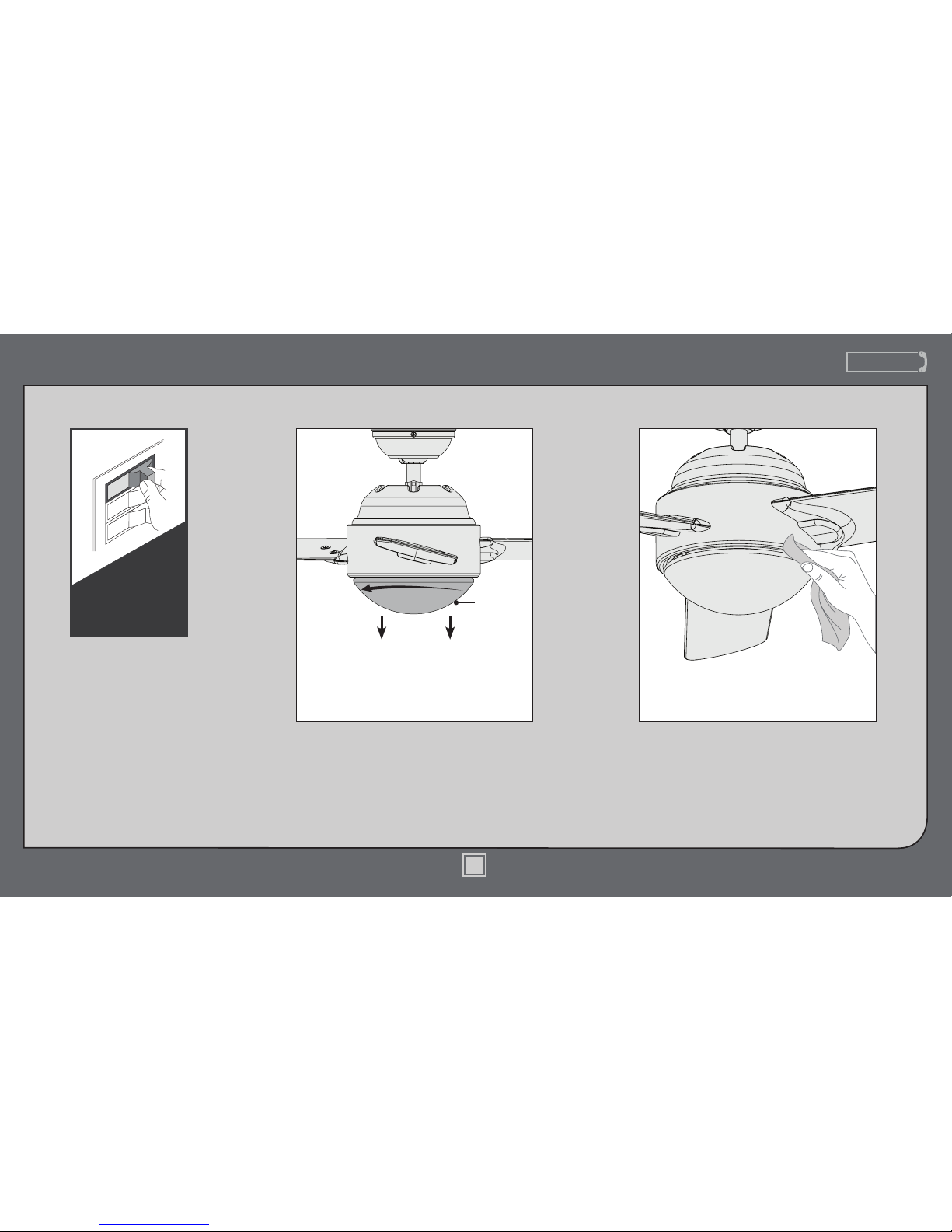
Maintenance & Cleaning
Cleaning the fan - use soft brushes or
cloths to prevent scratching. Cleaning
products may damage the nishes.
Be sure to turn off
power to the fan
before performing
any maintenance or
relamping.
OFF
Turn Power
Changing the bulbs - carefully rotate the globe
counterclockwise until it comes loose from
the tabs and lower it from inside the light kit.
Unscrew the bulb and replace it with a bulb of
the same type and wattage. Reinstall the globe.
Globe
Page 18
www.CasablancaFanCo.com
1.888.227.2178
18
M8509-01 • 06/24/13 • © Casablanca Fan Company
Troubleshooting
Excessive wobbling
• Tighten all blade screws until
they are snug.
• Turn the power off, support
the fan carefully, and check
that the hanger ball is
properly seated.
• Use the provided balancing
kit and instructions to balance
the fan.
Noisy Operation
• Tighten the blade screws until
they are snug.
• Check to see if any of the
blades are cracked. If so, replace
all of the blades.
Lights dim when turned on or
do not turn on at all.
• Make sure the wattage of the
light bulbs installed matches
the specications on the
light sockets (see page 17 for
instructions on changing the
bulbs).
Fan doesn’t work
• Press a fan speed button (1-4).
• Check the circuit breaker to
ensure the power is turned on.
• Check the wall control battery.
• Make sure that you have paired
the wall control.
• Make sure the blades spin freely.
• Turn off power from the circuit
breaker, then loosen the canopy
and check all the connections
according to the wiring diagram
on page 10-11.
AUTHORIZED SERVICE CENTERS
For the most updated listing of Casablanca Authorized
Service Centers, visit www.CasablancaFanCo.com or
call toll free 1-888-227-2178.
Remote doesn’t work
• Install a fresh battery in the wall
control.
• Make sure you have paired the
remote.
 Loading...