

CAS CUW Series, CUX Series, XB series, CU series Owner's Manual
2
3
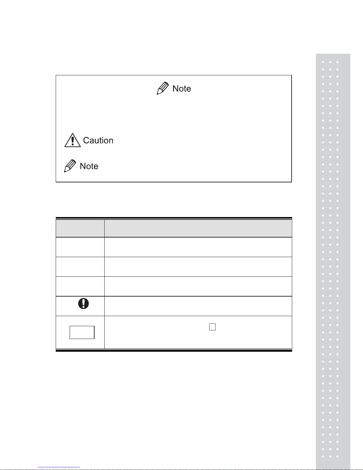
Notation Conventions
This instruction manual uses the following notation conventions to indicate
Safety Precautions and additional information.
Indicates a potentially hazardous situation that may
result in injury to personnel or equipment damage.
Provides additional information needed to properly
use the balance.
Other conventions used in this manual include:
Item Description
1,2,3....
Indicates the step number in a procedure or a sequence of changes in
the balance display.
[ ] key
Indicates the operation key on the balance. See 2.2.
mass display
Indicates that the balance is in the weighing mode and mass is
displayed in one of the weighing units.
These sections include information to make using the balance more
convenient.
NO.
Indicates the menu item to be selected.
The number in the is the number of the menu item on the
Menu Map.
See 7.2 “Menu Map”.
4
Safety Precautions
To ensure safe and proper operation of the balance, observe the following
precautions.
x Do not use the balance in hazardous ar eas.
This includes areas where the balance is expose to dust or flammable gases
and liquids.
x Use the AC a dapter specifie d by Shimadzu.
To prevent electric shock, never disassemble the AC adapter.
The AC adapter is designed for indoor use. Do not use the AC adapter in
exterior environments or where it may be splashed by water.
Ensure that the power supply voltage meets the indicated range of the
AC adapter.
x Handle the balance carefully.
The balance is a precision instrument of solid design.
x Do not connect peripheral devices other than those recommended
by Shimadzu.
The balance may not operate properly if peripheral devices other than
those specified in this manual are used. The specifications of the RS232C/AUX connector are described in Appendix 4. Connect the peripheral
devices according to the methods described in this instruction manual.
x Do not disassemble the balance, access ories, or peripheral unit.

5
Declaration Of Conformity
CAS Corporation declares that the following products:
UW Series and UX Series Electronic Balances
conform to the following directives.
Directives
EMC directive 89/336/EEC amended by 92/31/EEC, 93/68/EEC
EN55022: 1994 / A1: 1995 / A2: 1997 (Class B)
EN55024: 1998
EN61000-3-2: 1995 /A1: 1998 /A2: 1998, EN61000-3-3: 1995
Low Voltage directive 73/23/EEC amended by 93/68/EEC
EN60950: 1992 /A1: 1993 /A2: 1993
Weighing Instruments Department
Analytical & Measuring Instruments Division
CAS CORPORATION
CAS BLDG., #440-1, SUNGNAE-DONG,
GANGDONG-GU, SEOUL, KOREA

6
CAS Balances and 21 CFR Part 1 1
21 CFR Part 1 1
21 CFR Part 11, Electronic Records, Electronic Signatures, Final
Rule (often referred to as Part 11) is the United States Food and
Drug Administration (FDA) regulation affecting computer resources
and electronic records that are used for any document that is
required to be kept and maintained by FDA regulations.
Requirements concerning computer resources security are key elements in Part 11.
The controls implemented as a result of security related requirements
are intended to result in trusted records.
CAS CLASS-Balance Agent
CAS provides a means for compliance with 21 CFR Part 11
with CAS CLASS-Balance Agent software, part of a comprehensive
laboratory data management system, CAS CLASS Agent.
Ask your CAS representative about it.
CAS WindowsDirect
When CAS balances are integrated with laboratory software by
means of our WindowsDirect function, no communication software is required
or used.
The CAS balance functions as a primary device in the system,
just as a keyboard, mouse or other data entry hardware does.
For this reason, system validation and compliance may be greatly
simplified with the use of CAS balances.
Two-way Communication
CAS balances have always been computer friendly and they
can be set up for bi-directional communication as part of a fully automated
production system or LIMS.
This manual includes the command codes and information needed
by programmers to integrate CAS balances with their software.

7
Notation Conventions
Safety Precautions
1. Introduction.................................................................................................................................11
2. Name and Function of Components........................................................ 12
2.1 Components........................................................................................................12
2.2 Key Panel and Operation................................................................................... 14
2.3 Balance Display and Function ..........................................................................15
3. Specifications.........................................................................................................16
4. Installation..............................................................................................................17
4.1 Choosing the Installation Site............................................................................17
4.2 Unpacking and Delivery Inspection .................................................................19
4.3 Installation ..........................................................................................................22
4.4 Turning ON the Power.......................................................................................27
4.5 Span Calibration.................................................................................................28
5. Basic Operation...................................................................................................30
5.1 Weighing.............................................................................................................30
5.2 Changing the Unit Display................................................................................ 31
6. WindowsDirect Function...............................................................................32
6.1 Introduction: Experience it!...............................................................................32
6.2 Set Up WindowsDirect......................................................................................32
6.2.1 Setting Up the Balance.......................................................................... 32
6.2.2 Cable Connection...................................................................................33
6.2.3 Setting Up the Computer.......................................................................33
6.2.4 Start and Checking Operation............................................................... 35
6.3 Troubleshooting .................................................................................................36

8
7. Menu Item Selection............................................................................................. 38
7.1 What is the Menu?............................................................................................. 38
7.2 Menu Map.......................................................................................................... 38
7.3 Menu Item Selection Procedure........................................................................39
7.4 Setting Numeric Values ..................................................................................... 41
7.5 Related Useful Functions .................................................................................. 42
7.5.1 Last Menu Recall................................................................................... 42
7.5.2 Returning to the Default Settings (menu reset)....................................42
7.5.3 Menu Lock............................................................................................. 43
8. Built-in Clock Set-up........................................................................................ 44
8.1 Date..................................................................................................................... 44
8.2 Date Output Style............................................................................................... 44
8.3 Time .................................................................................................................... 45
8.4 Setting Display During Stand-by...................................................................... 45
9. Display Selection................................................................................................. 46
9.1 Bar graph display............................................................................................... 46
9.2 Changing the Minimum Display Digit (10d:1d)............................................. 46
10. Calibration........................................................................................................... 47
10.1 What is calibration? ......................................................................................... 47
10.2 Calibration Execution...................................................................................... 48
10.2.1 Span Calibration Using the Built-in Weight (UW Series Only)....... 48
10.2.2 Calibration Check Using the Built-in Weight (UW Series Only) .... 49
10.2.3 Span Calibration Using External Weights ......................................... 50
10.2.4 Calibration Check Using External Weights ....................................... 51
10.3 Calibration Setting........................................................................................... 52
10.3.1 Selecting the Calibration Type............................................................ 52
10.3.2 PSC Fully-automatic Calibration (UW series only)..........................52
10.3.3 Clock-CAL Fully-automatic Calibration (UW series only) ............. 53
10.3.4 PCAL: Calibration of the Built-in Weight (UW series only) ...........54
10.3.5 PCAL Password Setting (UW series only)........................................ 55
10.4 For GLP/GMP/ISO Conformance .................................................................56
10.4.1 Calibration Report Setting...................................................................56
10.4.2 Balance ID Setting............................................................................... 56

9
11. Environment............................................................................................................ 57
11.1 Overview ..........................................................................................................57
11.2 Stability and Response (Averaging)................................................................ 57
11.3 Stability Detection Settings .............................................................................58
11.3.1 What is Stability Detection?................................................................ 58
11.3.2 Stability Detection Band......................................................................59
11.3.3 Timing of Stability Mark Illumination and Linked Operation..........60
11.4 Tracking............................................................................................................ 60
12. Units......................................................................................................................... 61
12.1 Unit Display Set-up .........................................................................................61
12.2 Percentage (%) Conversion.............................................................................62
13. Enhancing Productivity...............................................................................63
13.1 Checkweighing and Target Display................................................................ 63
13.1.1 Checkweighing (Comparator) Display Type 1..................................64
13.1.2 Checkweighing (Comparator) Display Type 2..................................64
13.1.3 Target Mode .........................................................................................65
13.2 Piece Counting (PCS)...................................................................................... 66
13.3 Auto Print..........................................................................................................67
13.4 Auto Zero..........................................................................................................69
13.5 Zero Range....................................................................................................... 70
13.6 Taring/Printing at Stability...............................................................................71
13.7 Pretaring Value .................................................................................................72
14. Application Functions...................................................................................73
14.1 Solid Specific Gravity Measurement..............................................................73
14.2 Liquid Density Measurement..........................................................................75
14.3 Peak Hold .........................................................................................................77
14.4 Interval Timer...................................................................................................79
14.5 Add-on Mode ...................................................................................................80
14.6 Animal Weighing .............................................................................................82
14.7 Formulation Mode........................................................................................... 85

10
15. Connecting Peripheral Instruments..................................................... 87
15.1 Electronic Printer ............................................................................................. 87
15.2 Personal Computer - RS-232C -..................................................................... 88
15.2.1 Connecting the Cable ..........................................................................88
15.2.2 Data Format ......................................................................................... 89
15.2.3 Using Command Codes...................................................................... 91
15.2.4 Multi-Connection Mode ..................................................................... 96
15.3 Communication Setting...................................................................................99
15.3.1 Overview.............................................................................................. 99
15.3.2 Handshaking ........................................................................................ 99
15.3.3 Format ................................................................................................100
15.3.4 Communication Speed......................................................................100
15.3.5 Parity / Bit Length .............................................................................100
15.3.6 Stop Bit............................................................................................... 100
15.3.7 Delimiter ............................................................................................101
15.4 Decimal Point Symbol in Output Data ........................................................101
16. Maintenance and Transportation........................................................ 102
16.1 Maintenance...................................................................................................102
16.2 Moving the Balance....................................................................................... 102
17. T r oubleshooting.............................................................................................. 103
17.1 General Display .............................................................................................103
17.2 Error Display.................................................................................................. 104
17.3 Troubleshooting .............................................................................................105
17.4 LCD (Liquid Crystal Display) Check . ........................................................ 105
Appendices................................................................................................................106
A-1. Menu Map...................................................................................................... 106
A-2. Standard Accessories and Maintenance Parts List...................................... 111
A-3. Optional Accessories List..............................................................................112
A-4. Specifications of Connectors........................................................................ 113
A-5. Table of Unit Conversion Constants ............................................................ 114
A-6. Performance Checks .....................................................................................115
A-7. Below-Weigh Hook Dimensions ................................................................. 116
A-8. Notes on WindowsDirect.............................................................................. 117
A-9. Index............................................................................................................... 119

11
1. Introduction
CAS UW/UX series of toploading balances are a product of our 80 year history of
developing and manufacturing weighing instruments.
CAS UW/UX series of toploading balances utilize the patented CAS UniBloc
sensor, introduced in 1989, to achieve high performance, fast response, and durability.
Available features include multiple units of measure, piece counting, checkweighing
functions, auto print, and GLP/GMP/ISO output including date and time data from a
built-in clock.
The new series also features CAS’s WindowsDirect communication, requiring no
software installation
to quickly integrate balances with lab or business software. This function eliminates data
input errors and offers extensive flexibility for application development without
compromising compliance or data security.
The UW series balance incorporates a motor-driven built-in calibration weight that can
automatically calibrate sensitivity without the use of external weights.
Read this manual carefully before using this instrument and keep it with the balance for
future reference.
This manual refers to the different types of UW and UX series (UW/UX series) balances
as follows:
H type : UW/UX H
S type : UW/UX S
Where : represents the figure indicating the capacity, H indicates
high resolution and S indicates standard resolution.
The type of balance is classified as “large pan” or “small pan” depending on the capacity.
The small pan models with minimum display of 0.001g come with a standard windbreak.
Accordingly, the models are classified into the following three groups in “4. Installation”.
a. Large pan models: Capacity 2200g or higher
b. Small pan models: Capacity 820g or lower
(minimum display 0.01g)
c. Small pan models: Capacity 820g or lower
(minimum display 0.001g, windbreak standard)
Microsoft® and Windows® are registered trademarks of Microsoft Corporation.
Names of companies and products are trademarks or registered trademarks of the companies.
Copyright 2002 by ⓒ CAS CORPORATION, SEOUL KOREA
12
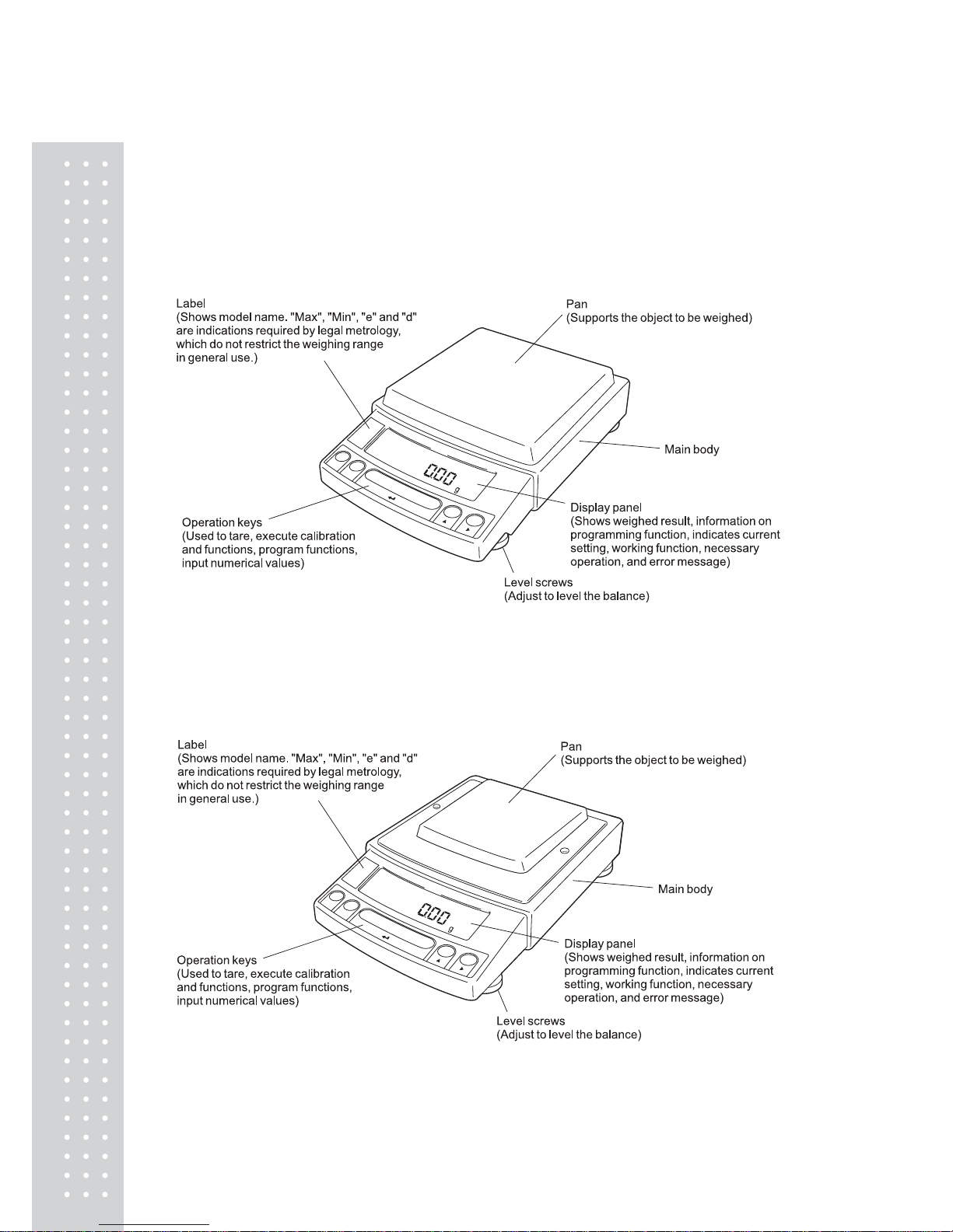
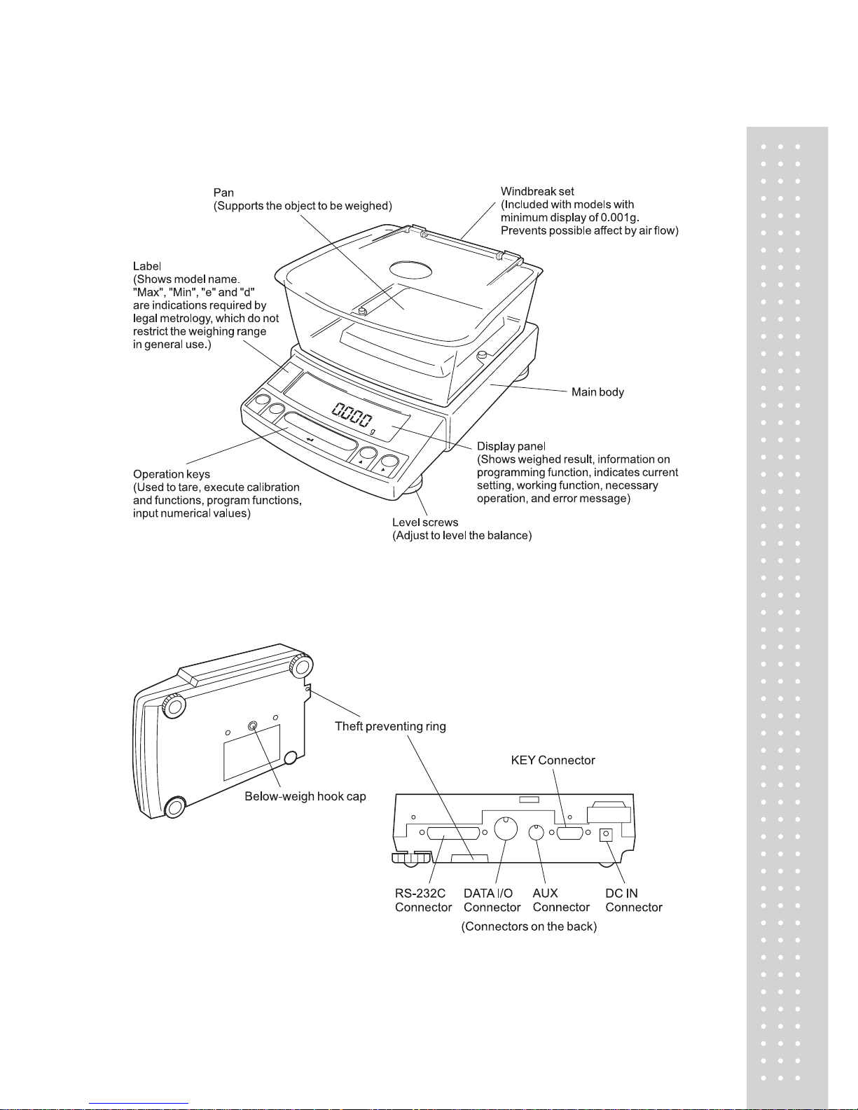
2. Name and Function of Components
2.1 Components
a. Large pan model
b. Small pan model (minimum display 0.01g)
13
c. Small pan model (minimum display 0.001g, windbreak st andard)
a, b, c. common
1
4
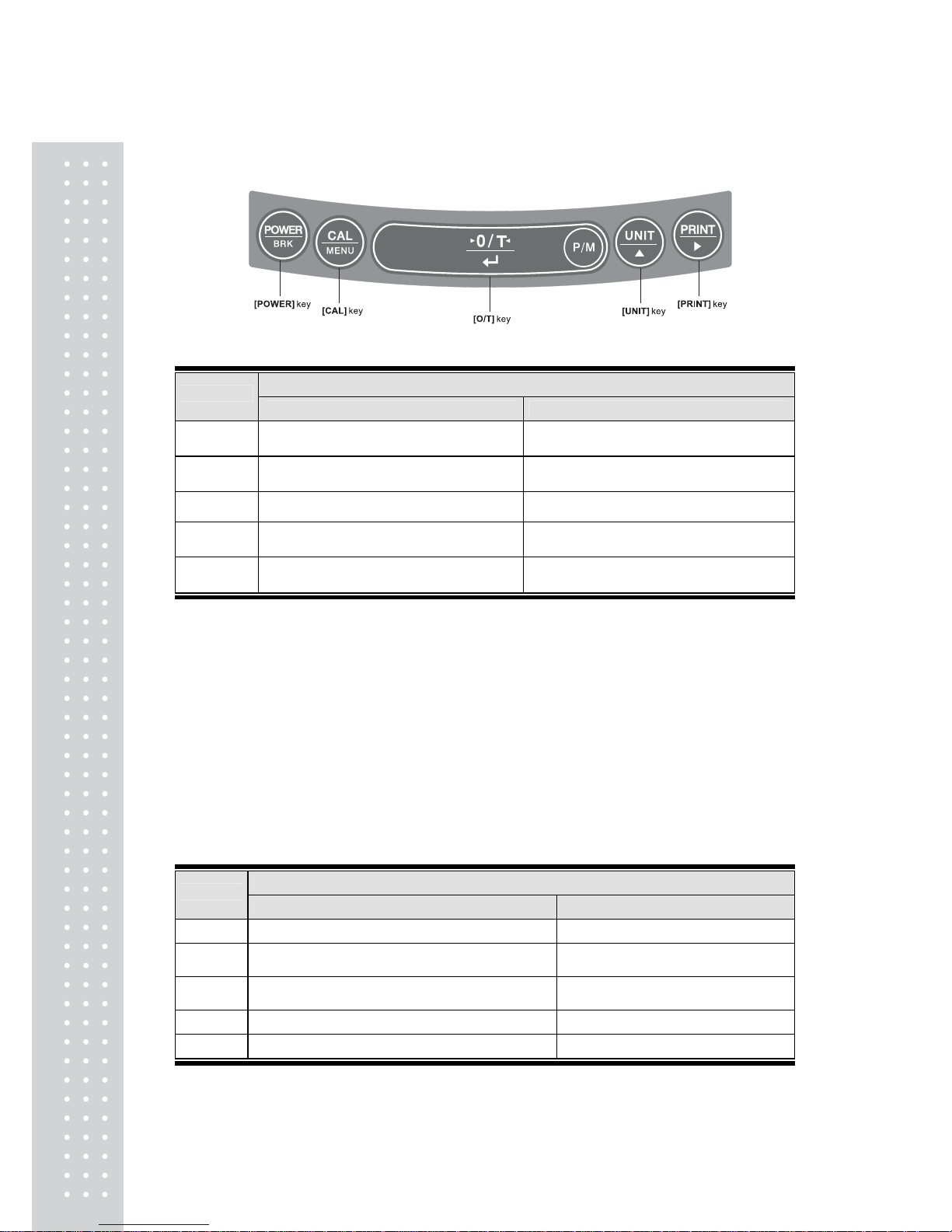
2.2 Key Panel and Operation
Functions of the keys
During Weighing
Key
Press Once and Release Press and Hold for About 3 Seconds
[POWER]
Switches between the operation and standby
modes.
Exits the application function and returns to
the mass display.
[CAL]
Enters span calibration or menu item
selection. (*1)
Displays the last menu item that was set.
(Last menu recall)
[O/T] Tares the balance. (Displays zero.)(*2) (*5) Displays the Pretare value.
[UNIT]
Changes the weighing unit or selects
specific gravity measurement. (*3)
Switches between the 1d and 10d
display. (*4)
[PRINT]
Sends the displayed value to a peripheral
device.
Sends the date and time to a peripheral
device.
*1 This key is used to set values when percent (%), number (PCS), solid specific gravity
(??d), or liquid specific gravity (▼d) are displayed.
*2 When a Pretare value is set, zero is not displayed and [- Pretare value] is displayed.
*3 Units other than “g” must be set up before they can be used for measurement. Only gram
(g), percent (%), and piece counting (PCS) are set-up before shipment. To set up other
units or specific gravity measurement, refer to section 12., or 14.1, 14.2.
*4 When the unit is set to 10d, the resolution of the minimum display is decreased by one
decimal place.
*5 In Pouring mode (See 11.2), the right-most part of [O/T] key marked with a circle
functions as the switch for environmental condition setting. Otherwise this part functions
the same way as the other parts of [O/T] key.
During Weighing
Key
Press Once and Release Press and Hold for About 3 Seconds
[POWER] Returns to the previous menu level Returns to the mass display.
[CAL] Moves to the next menu item.
Displays the last menu item that was set.
(Last Menu Recall)
[O/T]
Selects or sets the currently displayed menu item,
or enter into the displayed menu.
No operation.
[UNIT] Increases the numeric value of the blinking digit by 1. No operation.
[PRINT] Moves to the next digit during numeric value entry. No operation.
15
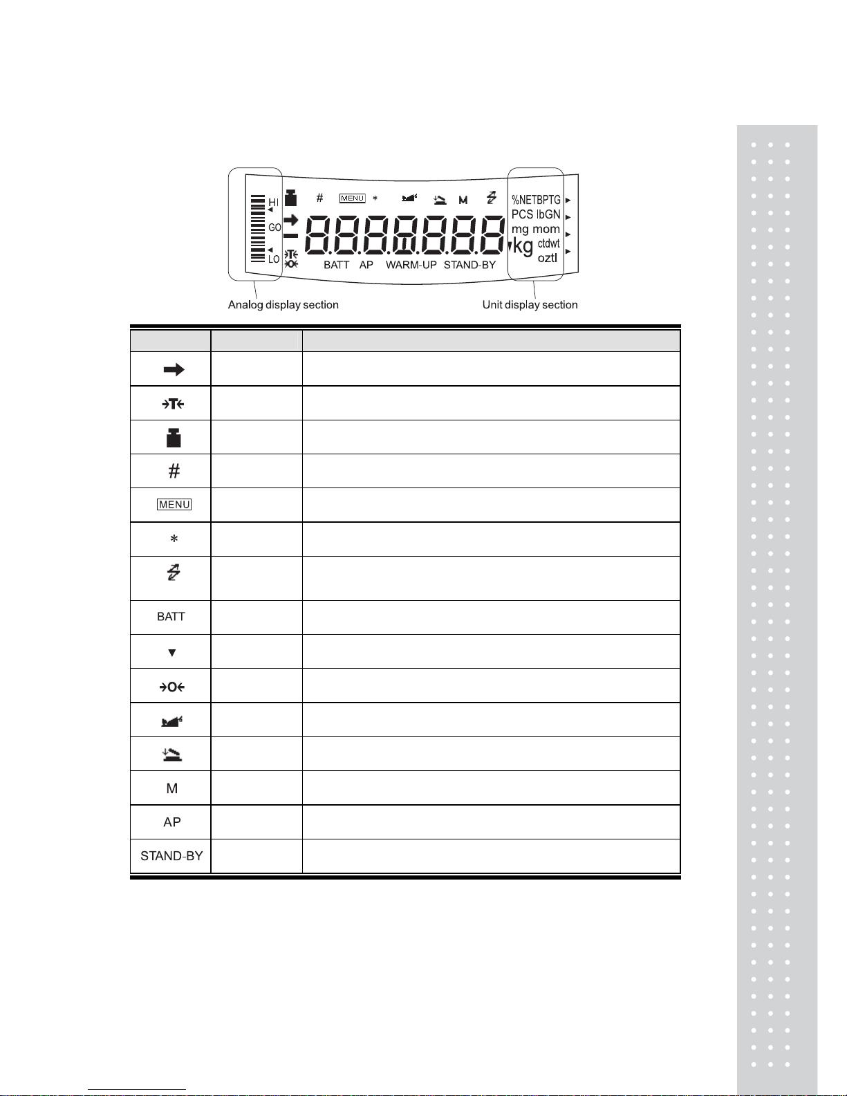
2.3 Balance Display and Function
Display Name Description
Stability mark
Indicates that the weighed value is stable. (*1) In menu item selection,
indicates currently selected item.
Tare symbol Indicates that a Pretare value has been set.
Weight symbol
Illuminates during span calibration. In menu selection, indicates setting
related to calibration. Blinks before automatic span calibration starts.
Number symbol Indicates numeric value entry.
Menu symbol Indicates that the menu lock is on. Illuminates during menu item selection.
Asterisk Indicates that the displayed numeric value is not a mass value.
Communication
symbol
Illuminates during communication to external equipment through the
RS-232C or DATA I/O connector. In menu selection, indicates setting
related to communication.
Battery symbol
When the balance is operated with the optional battery pack, this symbo
illuminates to indicate that the battery voltage has dropped.
Inverse triangle
symbol
Indicates the set-up of solid specific gravity measurement. Used as a
substitute for the decimal point.
Zero symbol Indicates the set-up of Auto Zero function.
Animal symbol Indicates the set-up of Animal Weighing function.
Add-on symbol Indicates the set-up of Add-on mode or Formulation mode.
Memory symbol Indicates the set-up of Formulation mode.
Auto Print
symbol
Indicates the set-up of Auto Print function.
Stand-by
symbol
Illuminates when the balance power is in the standby mode.
Also illuminates when the application function has entered the standby mode.
*1 Stability mark
The displayed value may change while the stability symbol remains illuminated if the
load is changing slowly or if the stability detection band has been set to a large value.
16
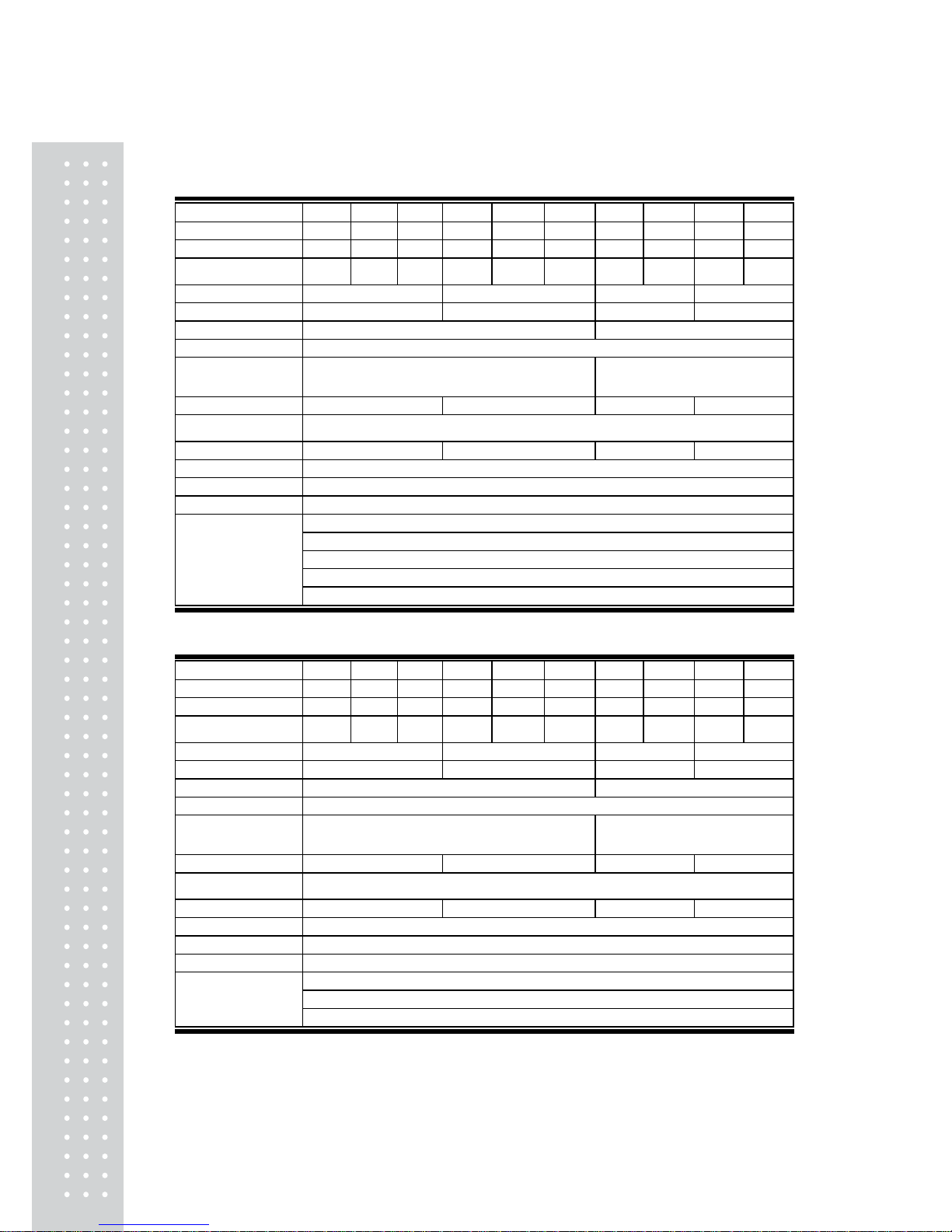
3. Specifications
UW Series Model UW220H UW420H UW620H UW2200H UW4200H UW6200H UW420S UW820S UW4200S UW8200S
Capaci ty 220g 420g 620g 2200g 4200g 6200g 420g 820g 4200g 8200g
Minimu m disp la y 0.001g 0.001g 0.001g 0.01g 0.01g 0.01g 0.01g 0.01g 0.1g 0.1g
Calibration range
with external weights
100-
220g
100-
420g
100-
620g
1000-
2200g
1000-
4200g
1000-
6200g
100-
420g
100-
820g
1000-
4200g
1000-
8200g
Repeatability (σ) ≤0.001g ≤0.01g ≤0.008g ≤0.08g
Linearity ±0.002g ±0.02g ±0.01g ±0.1g
Response time (s) 1.5-2.5 0.7-1.2
Ambient temperature (°C) 5-40
Temperature coefficient of
sensitivity
(ppm/°C) (10 - 30°C)
±3 ±5
Pan size (mm) approx. 108×105 170×180 108×105 170×180
Main body dimensions
(mm) approx.
190W×317D×78H
Weight (kg) approx. 3.4 4.6 3.4 4.6
Display LCD with backlight
Power requirements DC, 10 to 15.5V, 500mA (plug polarity: center negative)
Data I/O RS-232C
WindowsDirect
PSC
Clock-CAL
GLP/GMP/ISO conformance
Features
Analog display, % display, PCS, User unit, Animal weighing, Specific gravity measurement S/W, Checkweighing
UX Series Model UX220H UX420H UX620H UX 2200H UX 4200H UX 6200H UX 420S UX 820S UX 4200S UX 8200S
Capaci ty 220g 420g 620g 2200g 4200g 6200g 420g 820g 4200g 8200g
Minimu m disp la y 0.001g 0.001g 0.001g 0.01g 0.01g 0.01g 0.01g 0.01g 0.1g 0.1g
Calibration range
with external weights
100-
220g
100-
420g
100-
620g
1000-
2200g
1000-
4200g
1000-
6200g
100-
420g
100-
820g
1000-
4200g
1000-
8200g
Repeatability (σ) ≤0.001g ≤0.01g ≤0.008g ≤0.08g
Linearity ±0.002g ±0.02g ±0.01g ±0.1g
Response time (s) 1.5-2.5 0.7-1.2
Ambient temperature (°C) 5-40
Temperature coefficient of
sensitivity
(ppm/°C) (10 - 30°C)
±3 ±5
Pan size (mm) approx. 108 × 105 170 × 180 108 × 105 170 × 180
Main body dimensions
(mm) approx.
190W × 317D × 78H
Weight (kg) approx. 2.7 2.9 2.7 2.9
Display LCD with backlight
Power requirements DC, 10 to 15.5V, 500mA (plug polarity: center negative)
Data I/O RS-232C
WindowsDirect
GLP/GMP/ISO conformance
Features
Analog display, % display, PCS, User unit, Animal weighing, Specific gravity measurement S/W, Checkweighing

1
7
4. Installation
4.1 Choosing the Installation Site
(1) Power supply
x Select an installation site that is near a power source to ensure that the attached
AC adapter is used properly. If this is not possible, an optional battery pack is available
as a special accessory.
x Verify that the supply power voltage conforms to that indicated on the AC adapter.
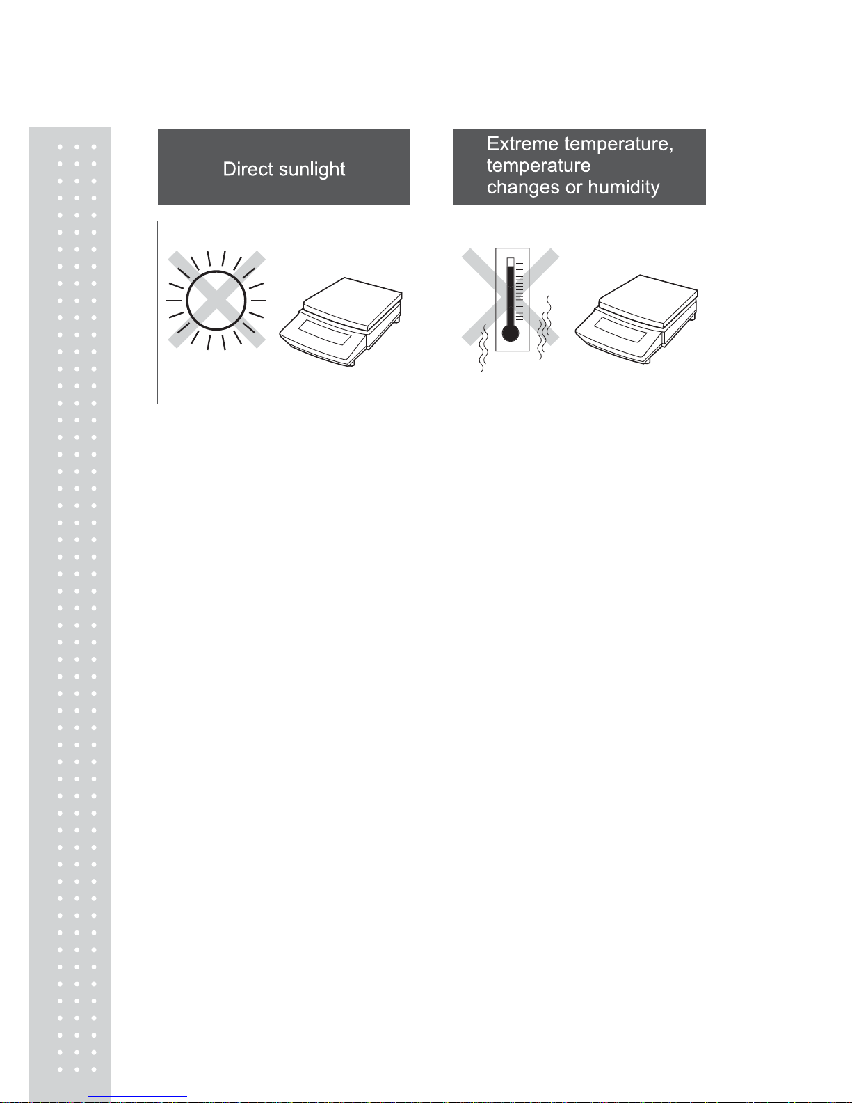
(2) Installation site
Avoid sites where the balance will be exposed to the following:
1
8
x Corrosive or flammable gasses
x Dust, wind, electromagnetic waves, or magnetic fields
Large capacity balances should be installed on a sturdy floor and table that can support
the total load of the balance AND object to be weighed.
19
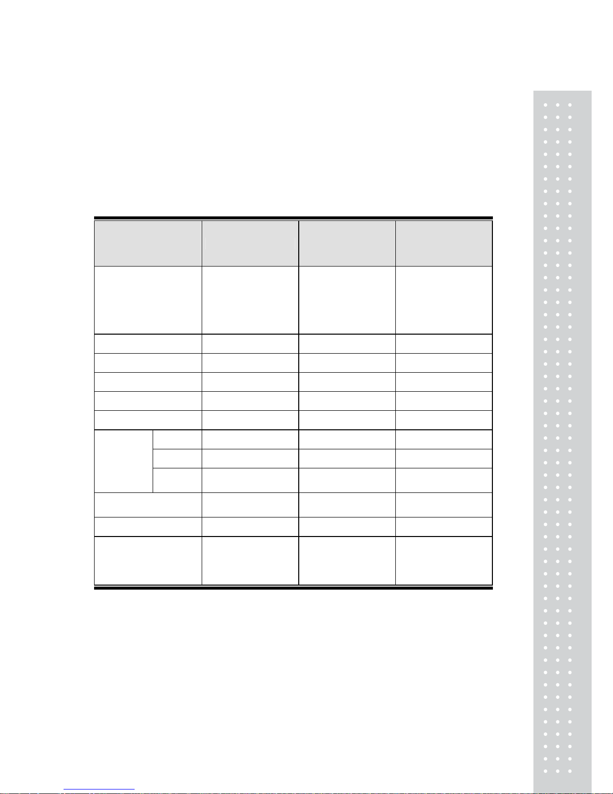
4.2 Unpacking and Delivery Inspection
Unpack and remove all the items from the delivery box. Check if all the listed items are
present and nothing has been damaged. Contact your local distributor in case of damaged
or missing items.
Standard packed item and quantity
Type a. Large pan model
b. Small pan model
(Minimum display
0.01g)
c. Small pan model
(Minimum display
0.001g)
Model
(UW/UX is “UW or UX”.
Additional suffix may
appear after H or S on
your balance.)
UW/UX2200H,
UW/UX4200H,
UW/UX6200H,
UW/UX4200S,
UW/UX8200S
UW/UX420S,
UW/UX820S
UW/UX220H,
UW/UX420H,
UW/UX620H
Balance main body 1 1 1
Pan supporter cap 4 4 4
Pan 1 1 1
AC adapter 1 1 1
Protective in-use cover 1 1 1
Main 0 0 1
Lid 0 0 1
Windbreak
set
Fixing
knob
0 0 2
Rubber cap 0
2 (installed on balance
main body)
2 (installed on balance
main body)
Stainless screw 0 2 2
Instruction manual
(incl. explanatory
operation sheet)
1 1 1
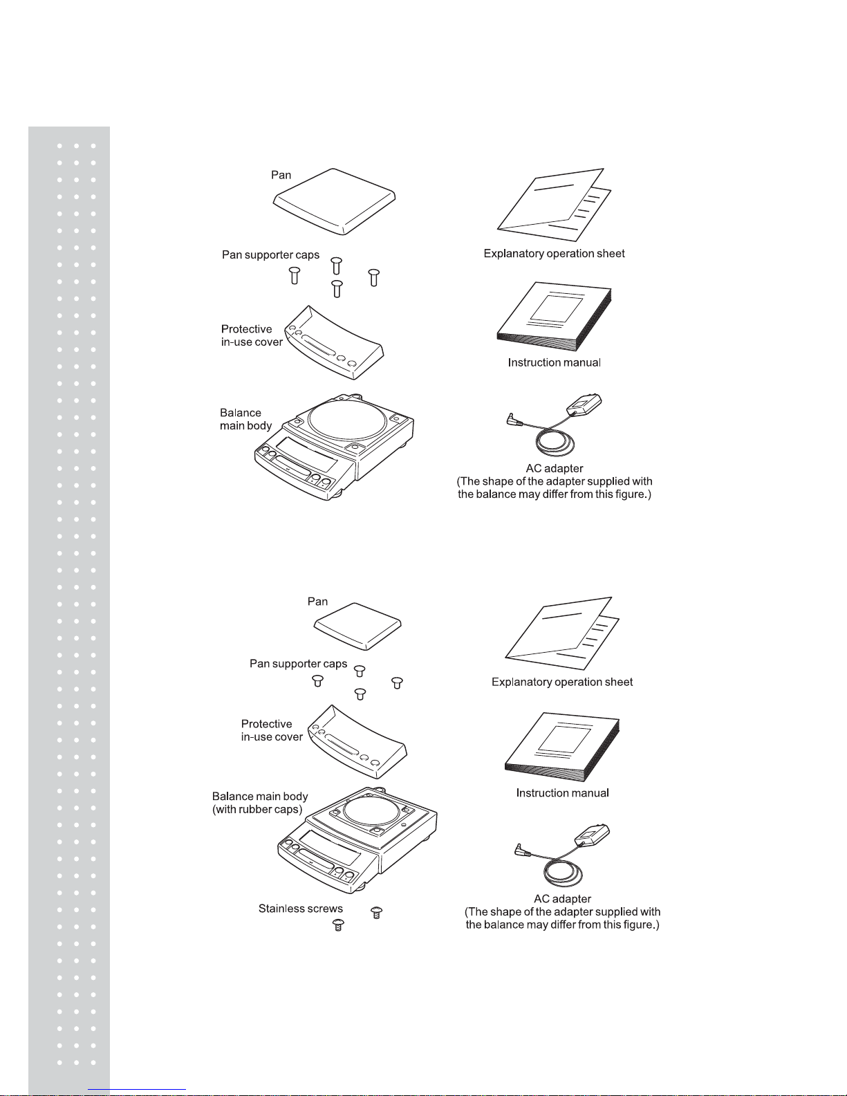
20
a. Large pan model
b. Small pan model (minimum display 0.01g)
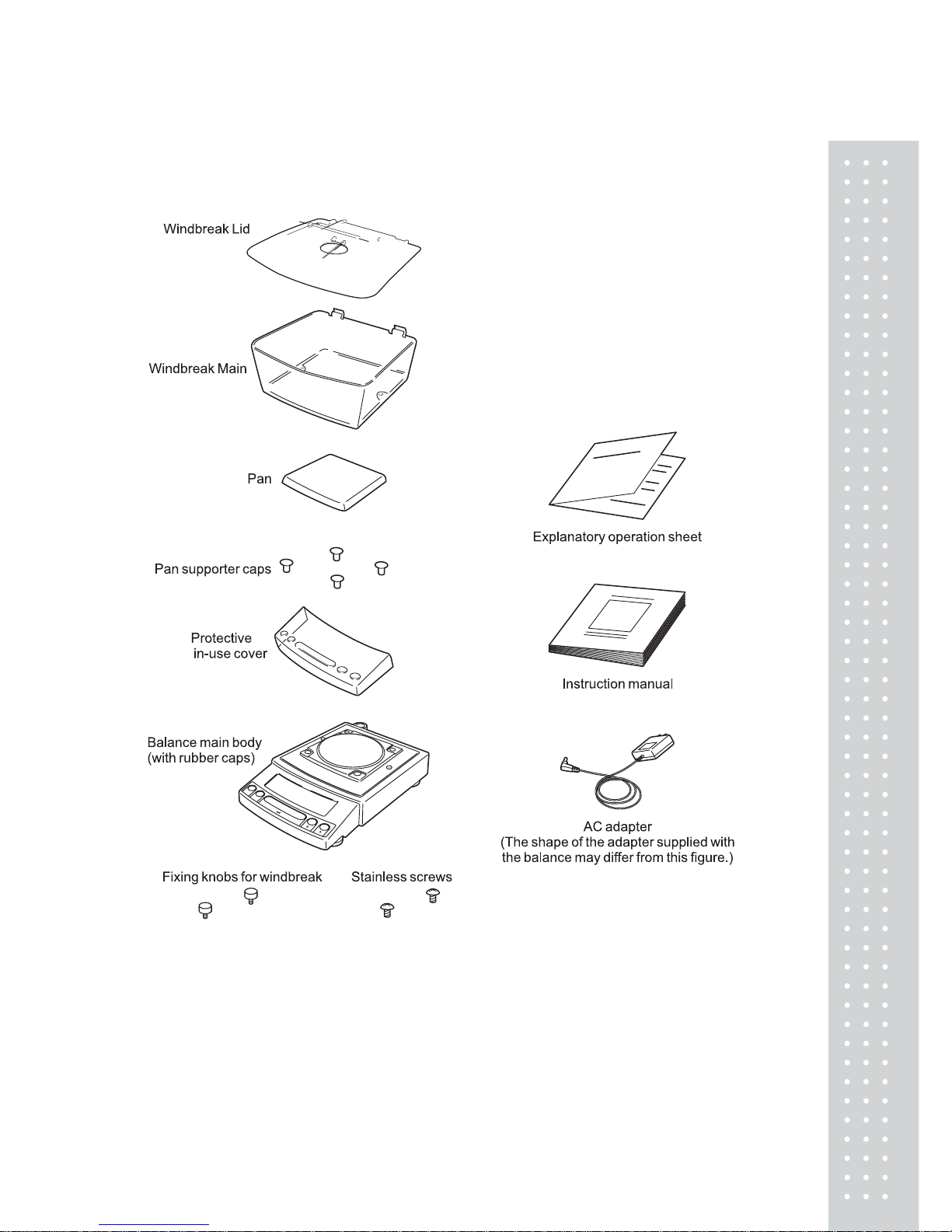
21
c. Small pan model (minimum display 0.001g)
22
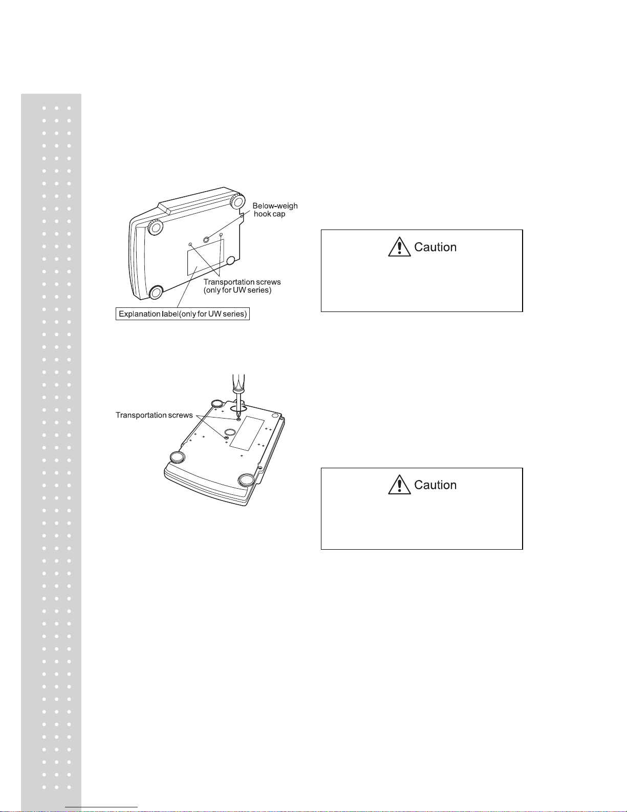
4.3 Installation
(Start at step 3 when installing a UX series balance. Prepare a plus (+) screw driver for a
UW series balance.)
1. Place the balance main body upside
down. (UW only)
Do not operate step 2 with the balance
placed on its side.
Place the balance on a smooth surface.
2. Referring to the explanation label on the
bottom of the balance, turn the two
transportation screws
counterclockwise until they tighten
again. (UW only)
When moving the balance again, turn the
two transportation screws clockwise until
they tighen. (UW only)
23
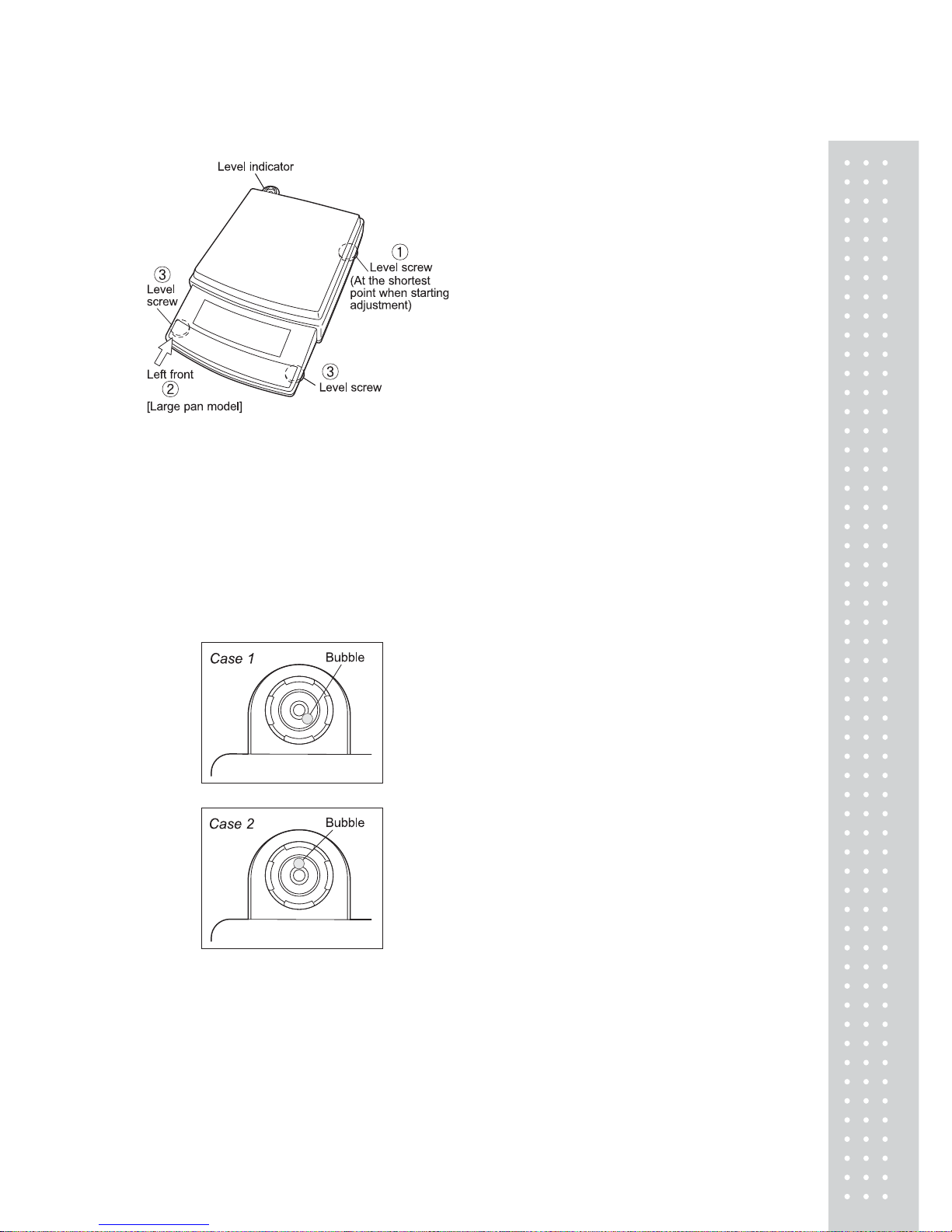
3. This balance has three level screws
(adjustable feet) at the right front, left
front and right rear corners.
Turning a level screw clock-wise
stretches the leg to raise the balance body
there.
Turning anticlockwise withdraws the leg
and lowers the balance body.
The level indicator locates at left rear.
The bubble of it is off center when the
balance is not placed level.
(1) Adjustment is made with the two front
level screws only. Accordingly, first turn
the right rear level screw anti① -
clockwise to withdraw its leg completely.
(2) While adjusting level screws and
observing the bubble, gently press the
left front corner of the balance ② so
that both front level screw feet ③ are
touching the table surface.
(3) Bubble moves to the highest position.
Therefore, adjust level screws ③ so that
the balance main body is lowered in the
direction of the bubble.
Case 1: Right front of the balance is too high.
T urn right front level scr ew anti-clockwise so
that the bubble moves towards center.
Case 2: Front of the balance is too low .
T urn both front level scr ews clockwise so
that the bubble moves towards center.
(4) When the bubble has come to the center
of the red circle, turn the right rear level
screw clockwise until its foot softly
touches the table surface. Verify the
balance sits stable with four feet.
2
4
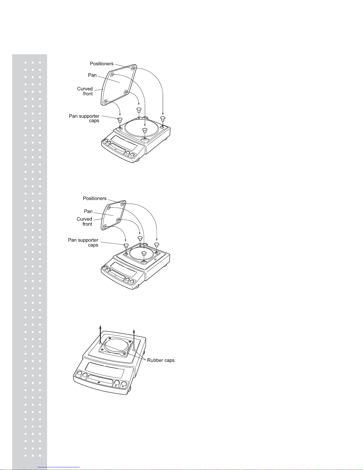
4. Install the pan. With small pan model with
minimum display of 0.001g, the standard
windbreak is also installed here.
a. Large pan model
Insert the four pan supporter caps into the
holes in the top of the balance. Place the
pan gently on pan supporter caps.
Positioners of the pan must fit pan
supporter.
b. Small pan model
(minimum display 0.01g)
Insert the four pan supporter caps into the
holes in the top of the balance. Place the
pan gently on pan supporter caps.
Positioners of the pan must fit pan
supporter.
The rubber caps on top of the main body may be
replaced with the stainless screws so that it will
be more secure when exposed to organic solvent.
c. Small pan model
(minimum display 0.001g,
windbreak standard)
(1) Pull out the two rubber caps from the
main body top.
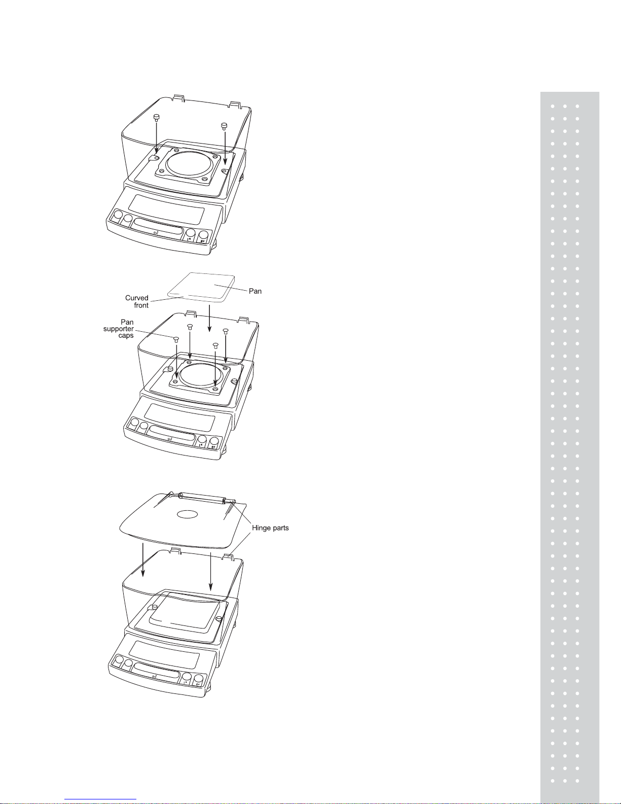
25
(2) Fit windbreak main on top of the balance
main body, and fasten it with two fixing
knobs.
(3) Insert the four pan supporter caps into the
holes in the top of the balance. Place the
pan on them. Positioners on the pan must
fit pan supporter caps.
(4) Place windbreak lid on top of windbreak
main fitting the hinge parts.
26
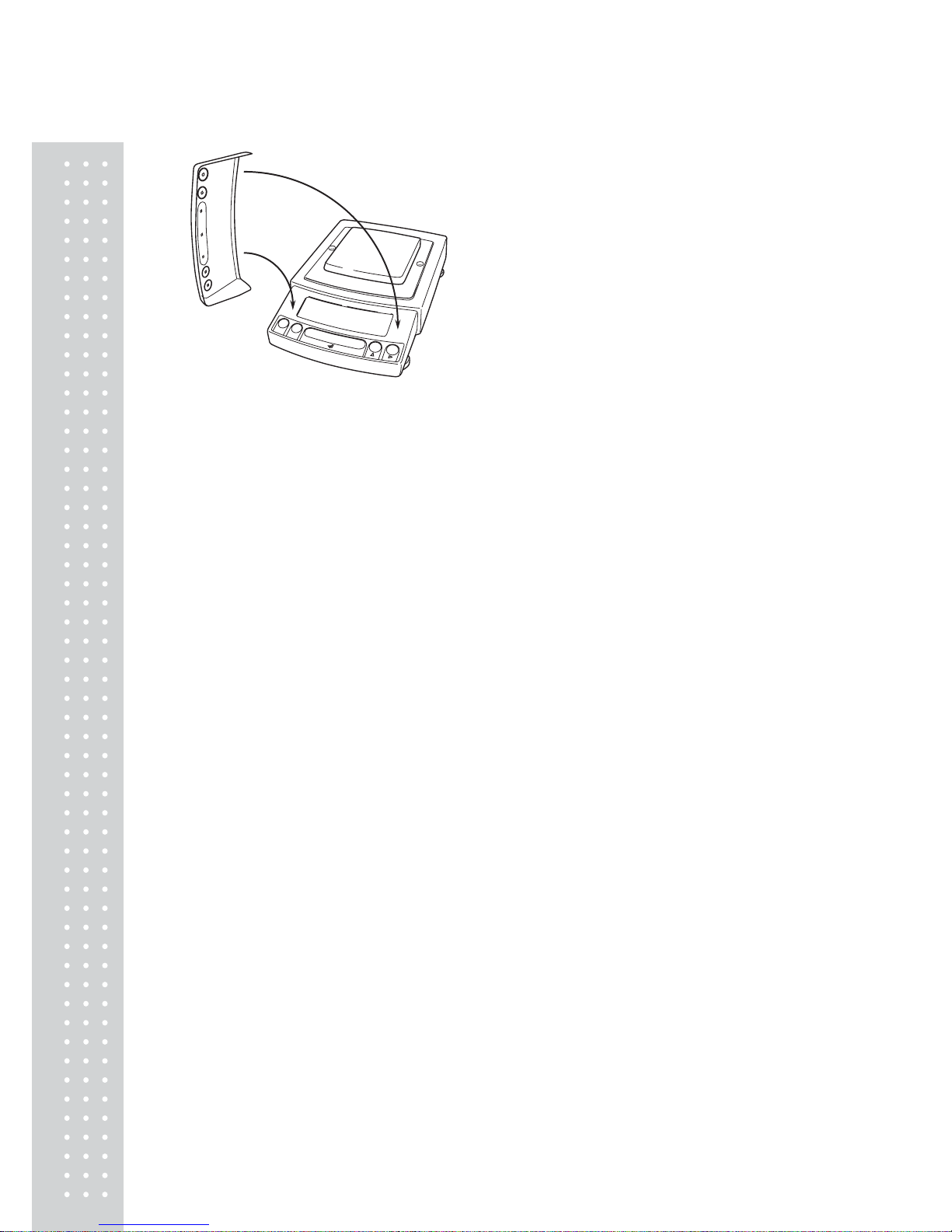
5. If you use protective in-use cover, peel off
the paper to expose the adhesive on it, then
fit it on the display and key part. Press the
adhesive parts gently.
2
7
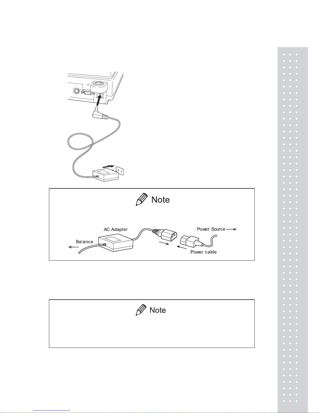
4.4 T urning ON the Power
1. Insert the plug of the AC adapter into the
DC IN connector on the rear of the
balance.
2. Insert the AC adapter into the power
source. The balance self-check is activated
and the following messages are displayed
in the order indicated.
[HELLo], [CHE 5], [CHE 4], [CHE 3],
[CHE2], [CHE1], [CHE0], whole lighting,
[oFF] ([CHE 5] and [CHE 4] are not
displayed for the UX series).
A power cable may be necessary to connect the AC adapter to the power
source, depending on the type of the AC adapter.
3. Press [POWER] key. The whole display
illuminates and then the display changes to
indicate the gram-display. The backlight is
illuminated.
When using the optional battery pack (special accessory), connect the fully
charged battery pack to the DC IN connector of the balance using the cable
attached to the battery pack.
2
8
4.5 Sp an Calibration
It is necessary to calibrate the balance after it is moved.
Verify that the balance is stable before performing the span calibration. To achieve a very
stable state, ensure that the balance has been turned on with the gram-display for at least one
hour, that the temperature is constant, that there are no breezes or vibrations and that the
balance is in an area isolated from the normal traffic flow.
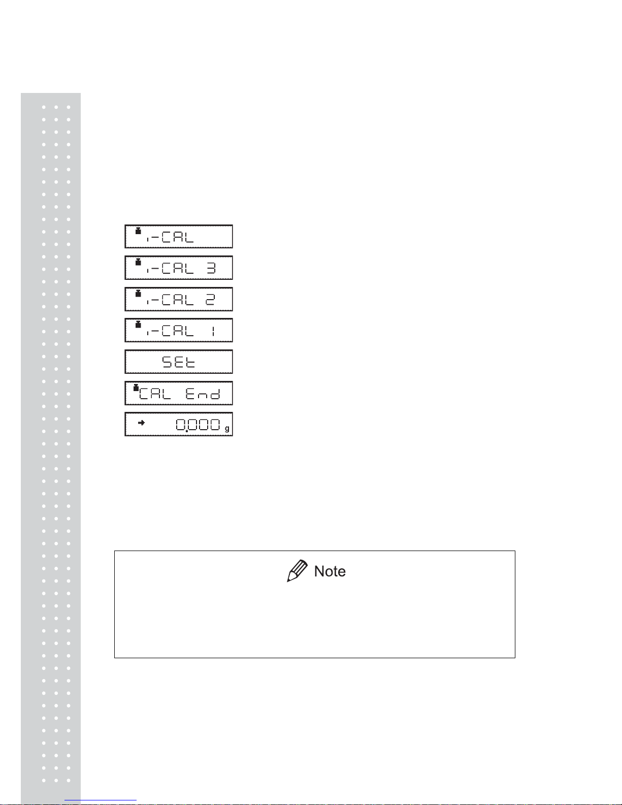
UW series [Span Calibration
Using the Builtin Weight]
1. Verify that the balance is in gram-display and that
the pan is empty.
2. Press the [CAL] key once. “i-CAL” is displayed.
3. Press the [O/T] key. After
“i-CAL3”...“i-CAL1”, “Set”, “CALEnd” are
displayed indicating the completion of span
calibration, the gram-display will appear.
This is the standard calibration type. Refer to 10.3.1 for use of external weights.
Span calibration should be performed again :
when the location of the balance is changed,
when the room temperature changes considerably,
periodically, according to the quality control plan of the user.
29
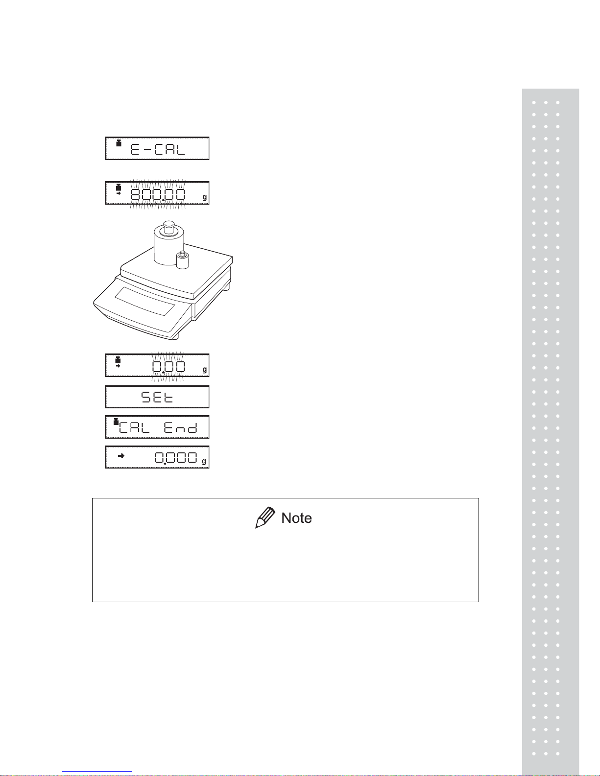
UX series [Span Calibration Using
External Weights]
1. Verify that the balance is in gram-display and
unload the sample from the pan.
(Example)
2. Press the [CAL] key once.“E-CAL” is displayed.
3. Press the [O/T] key.
The value of the correct calibration weight to be
loaded is displayed and blinks.
4. Load the indicated calibration weight and press the
[O/T] key.
5. When the zero display blinks, unload the weight
from the pan and press the [O/T] key. “Set” is
displayed briefly to indicate completion of span
calibration. Then the gram-display will return.
Span calibration should be performed again :
when the location of the balance is changed,
when the room temperature changes considerably,
periodically, according to the quality control plan of the user.
30
5. Basic Operation
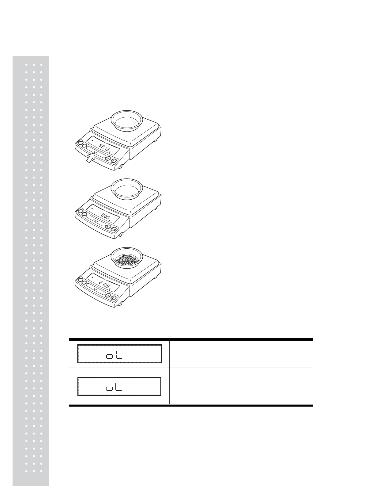
5.1 Weighing
1. If a weighing vessel (tare) is used, place it on the
pan and wait for the stability mark to illuminate.
2. Press the [O/T] key to zero the display.
(This operation is called “taring”.)
3. Place the object to be weighed on the pan.
4. Read the displayed value after the stability
mark is displayed.
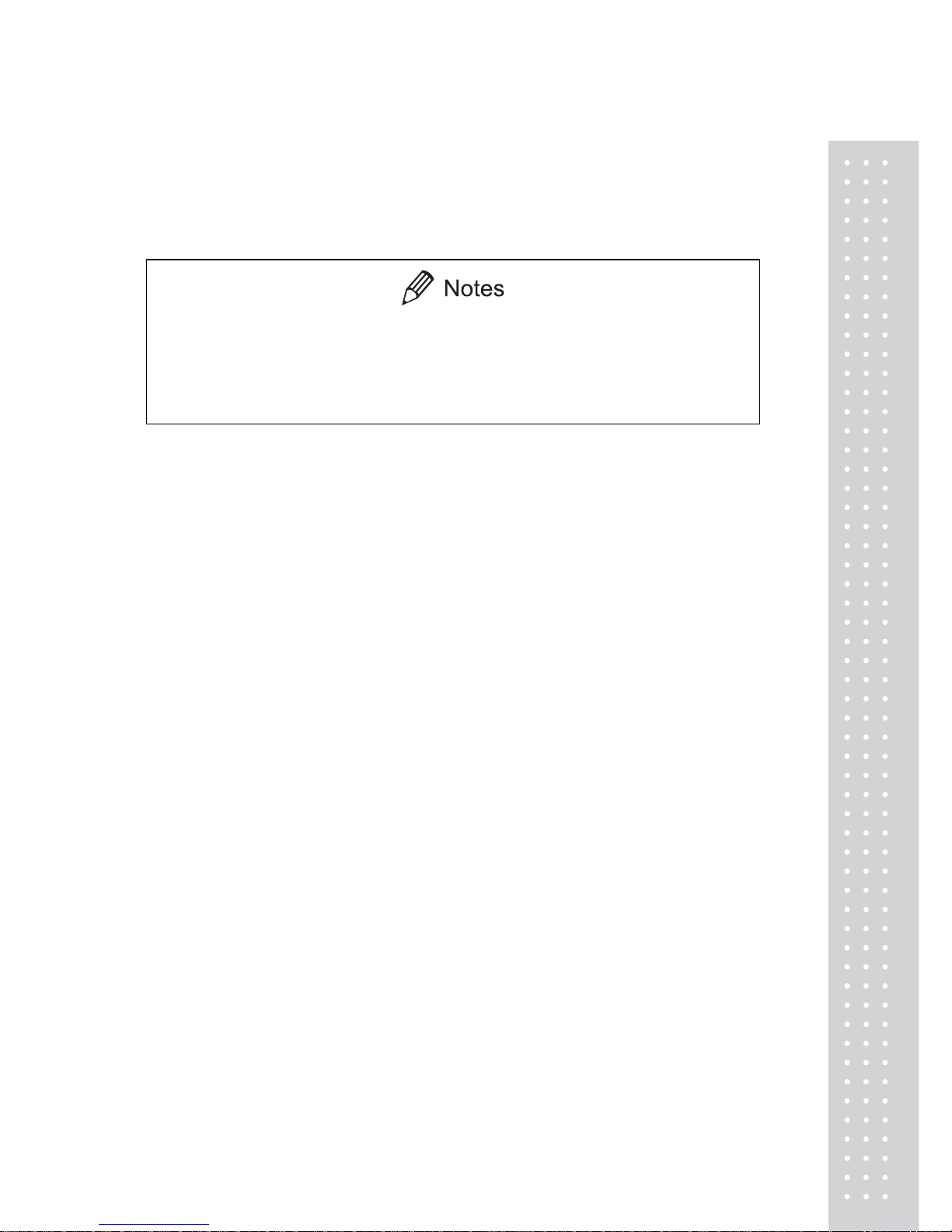
Error Displays During Weighing
Overload: Weighing capacity has been exceeded.
Negative Overload: The load on the balance is too light.
The pan is not adjusted properly.
For D-type balances, [-oL] will appear if the load is
below the low capacity range.
31
5.2 Changing the Unit Display
Every time the [UNIT] key is pressed, the unit display changes sequentially among those
set-up in 12.1 Unit Display Set-up. Gram, %, and PCS have been set-up before delivery.
x Before a unit can be displayed it must be registered in 12.1 Unit Display
Set-up.
x The registered units are displayed sequentially according to the order of
the 12.1 Unit Display Set-up.
 Loading...