

CAS X320 Quick Start Manual

IP69K Washdown Indicator
Quick Start Manual
(800) 223-4227
www.cas-usa.com
U21022050

Quick Start Manual Rev 1.33
003X-608-133 Page 1
Table of Contents
1. INTRODUCTION.............................................................2
1.1. Approvals................................................................2
1.2. Manuals ..................................................................2
2. SHIPPING CONTENTS ..................................................2
3. SPECIFICATIONS ..........................................................3
4. WARNINGS ....................................................................4
4.1. General ...................................................................4
4.2. Configuration Issues...............................................4
5. INSTALLATION ..............................................................5
5.1. Electrical Safety ......................................................5
5.2. opto-LINK................................................................6
6. CONNECTIONS..............................................................7
6.1. Cable Connections .................................................7
6.2. DC Power (DC PWR + , DC PWR –)......................7
6.3. Load Cell Connection .............................................7
6.4. Auxiliary Connections .............................................9
6.5. Connecting Shields...............................................15
6.6. Regulatory Sealing Requirements........................15
7. INSTRUMENT SETUP..................................................17
7.1. Calibration Counter...............................................17
7.2. opto-LINK..............................................................17
7.3. Access Full Setup .................................................18
7.4. Access Safe Setup ...............................................18
7.5. Exit Full or Safe Setup ..........................................18
7.6. Settings.................................................................18
8. ERROR MESSAGES....................................................27
8.1. Weighing Errors ....................................................27
8.2. Setup and Calibration Errors ................................28
8.3. Diagnostic Errors ..................................................29

Quick Start Manual Rev 1.33
Page 2 003X-608-133
1. Introduction
This manual contains information on the installation, calibration
and setup of the instrument.
1.1. Approvals
• C-tick approved and CE approved.
1.1.1. Trade versions
• NSC approval (4000 divisions at 0.8µV/division).
• NMI approval (4000 divisions at 0.8µV/division).
• NTEP approval (10000 divisions at 0.8µV/division).
1.2. Manuals
For more information on this instrument refer to the
Reference Manual, Quick Start Manual or
Communications Manual.
2. Shipping Contents
The following table identifies the items shipped with the
indicator. Please check that your packing box contains the
specified items.
Shipped Items Other Items (Optional)
• Indicator
• Operator Manual
• Quick Start Manual
• Trade Label (plastic)
• U Bracket
• opto-LINK Cable
• Power Supply
• Battery Pack with Charger
• Captive Security Screws
Quick Start Manual Rev 1.33
003X-608-133 Page 3
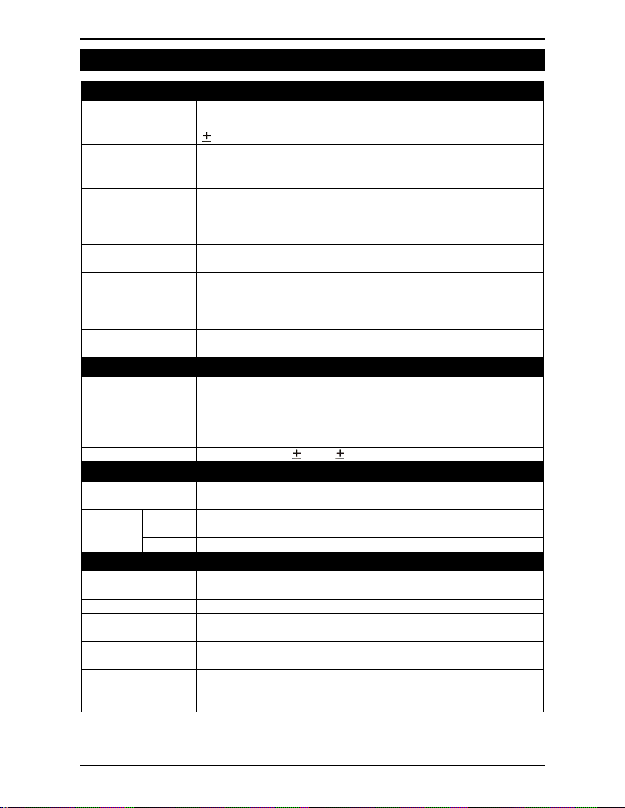
3. Specifications
Performance
Resolution
Up to 30,000 divisions, minimum of 0.25µV/division
(K307 up to 60,000 divisions)
Zero Cancellation
2.0mV/V
Span Adjustment 0.1mV/V to 3.0mV/V full scale
Stability/Drift
Zero: < 0.1µV/°C (+ 8ppm of deadload max)
Span < 8 ppm/°C, Linearity < 20ppm, Noise < 0.2µVp-p
Excitation 5 volts for up to 4 x 350 or 8 x 700 ohm load cells (4-wire or
6-wire plus shield)
Maximum total load cell resistance: 1,000 ohms
A/D Type 24bit Sigma Delta with 8,388,608 internal counts
A/D Conversion
Rate
20Hz with FIR filtering > 80dB
Operating
Environment
Temperature: –10 to +50°C ambient
Humidity: 100%
Storage: –20 to +50°C ambient
IP69K
Case Materials PC+Polyester alloy, PBT, Silicon Rubber, SS304 Stand
Packing Weights Basic Indicator: 2.0kg
Digital
Display LED Backlit LCD with six 20mm high digits with units and
annunciators
Setup and
Calibration
Full digital with visual prompting in plain messages
Digital Filter Sliding window average from 0.1 to 4.0 seconds
Zero Range Adjustable from 2% to 100% of full capacity
Power Input
Standard Power
Input
12 to 24VDC, 9.6, 12 and 24V batteries (2.5 VA max) -
ON/OFF key with memory feature
Variants AC AC Power supply: 110/240VAC 50/60Hz in 24VDC 1.25A
out
Battery 12V battery pack (rechargeable NiMH)
Features
opto-LINK Data
Coupling
Infra-red Connector for optional opto-LINK PC cable (to RS-
232 or USB PC port)
Correction Ten point linearity correction (K304 Only)
Outputs RS-232 automatic transmit, network or printer outputs.
Transmission rate: 2400, 4800 or 9600 baud
Assignable
Function Key
Unit switching, counting, manual hold, peak hold, live weight,
totalising
Drive Outputs 3 isolated high side drive outputs (400mA each 12-24VDC)
Battery Backed
Clock Calendar
Battery life 10 years minimum

Quick Start Manual Rev 1.33
Page 4 003X-608-133
4. Warnings
4.1. General
• Indicator not to be subject to shock, excessive vibration or
extremes of temperature (before or after installation).
• Inputs are protected against electrical interference, but
excessive levels of electro-magnetic radiation and RFI may
affect the accuracy and stability.
• For full EMC or for RFI immunity, termination of cable shields
and correct earthing of the instrument is essential.
• Indicator and load cell cable are sensitive to excessive
electrical noise. Install well away from any power or
switching circuits.
4.2. Configuration Issues
• Configuration and calibration can be performed from the front
panel, using digital setup. When Full Setup is used, all menu
items are accessible and care must be taken to ensure no
accidental changes are made to calibration and trade
settings.
• Enter a passcode to prevent unauthorised or accidental
tampering. If the passcode is lost, the manufacturer should
be contacted for further advice.

Quick Start Manual Rev 1.33
003X-608-133 Page 5
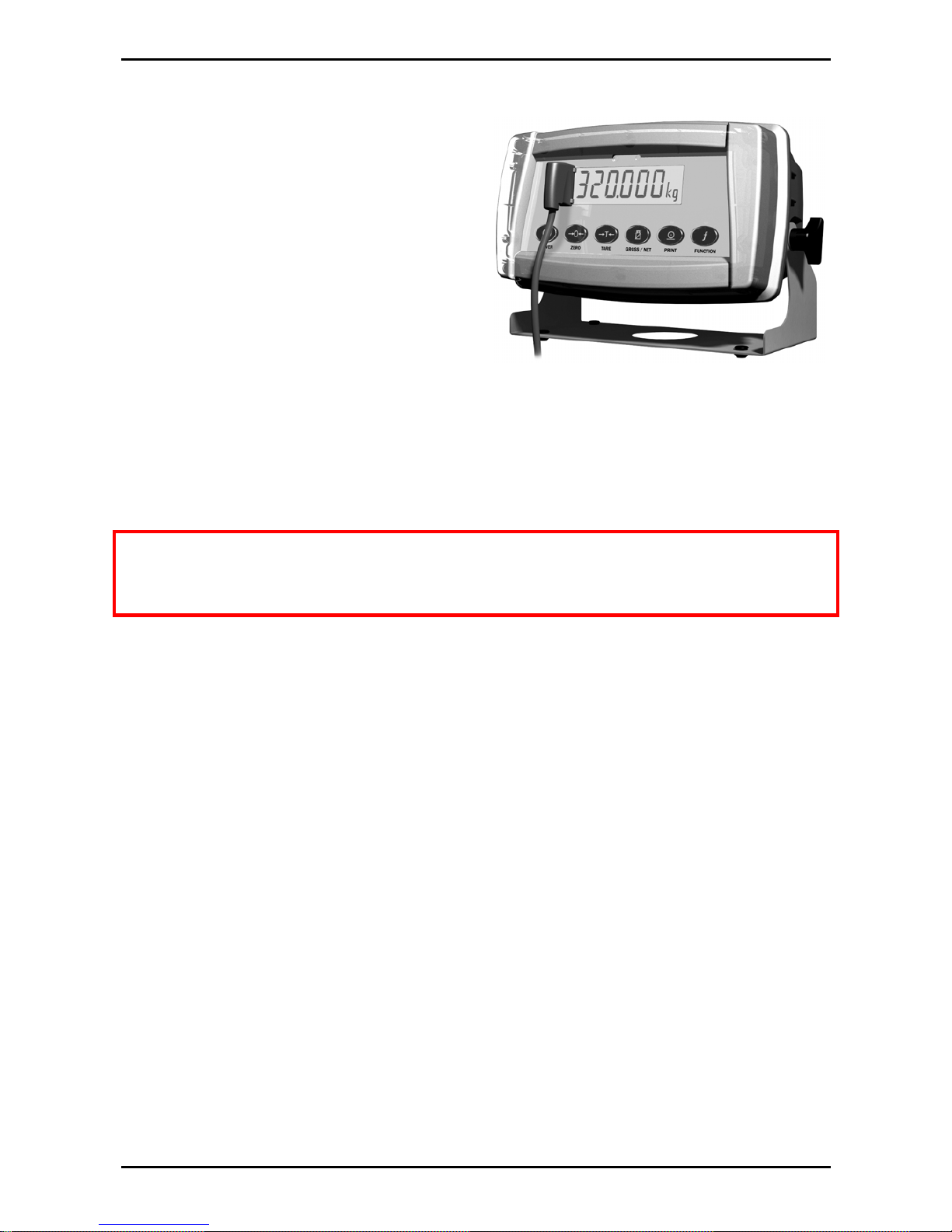
5. Installation
The following steps are required to set up the indicator.
• Inspect indicator to ensure good condition.
• Use connection diagrams to wire up load cell, power and
auxiliary cables as required.
• Connect Power to indicator and press <POWER> key to turn
the instrument On.
• Refer to the Instrument Setup section page 17 for information
on configuring and calibrating the instrument.
• To turn instrument Off press and hold <POWER> key for
three seconds (until display blanks).
5.1. Electrical Safety
• For your protection all mains electrical hardware must be
rated for environmental conditions of use.
• Pluggable equipment must be installed near an easily
accessible power socket outlet.
• To avoid the possibility of electric shock or damage to the
instrument, always switch off or isolate the instrument from
the power supply before maintenance is carried out.
Quick Start Manual Rev 1.33
Page 6 003X-608-133
5.2. opto-LINK
The optional opto-LINK cable
can be used to transfer setup
and calibration information
from a PC (eg. to be stored for
later use and/or transferred to
other instruments). It can also
be used to download software
upgrades to the instrument
from a PC.
• Attach the opto-LINK cable to the PC using the DB9 or USB
connector.
• Attach the opto-LINK head to the left side of the instrument
display using the permanent magnet located within the head of
the opto-LINK.
WARNING: The opto-LINK head contains a strong magnet and care
should be taken with its proximity to electronic media (eg. credit
cards, floppy disks, etc.) and/or other electronic instrumentation.
5.2.1. opto-LINK Activation
A long press of the <GROSS/NET> key will toggle the opto-LINK
infrared communications On/Off.
When the opto-LINK has been (enabled) the following will occur:
• The instrument briefly displays the prompt opto-L.
• The editing annunciators (ie. GRP, ITM, etc.) will flash for up to
five minutes while the instrument searches for activity. During
this period, the instrument also disables the RS-232
communications.
• After a 5 minute period of no activity, the opto-LINK will be
disabled and the editing annunciators will stop flashing. The
instrument will revert back to the normal RS-232
communications (ie. The SERIAL:TYPE setting will be reactivated).
Quick Start Manual Rev 1.33
003X-608-133 Page 7
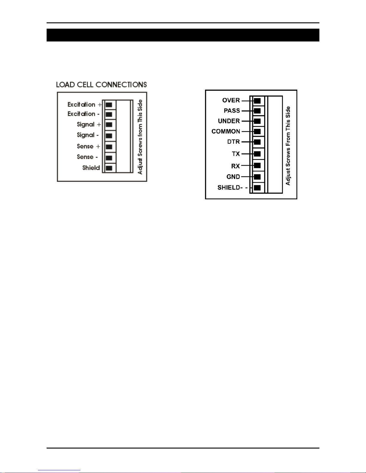
6. Connections
6.1. Cable Connections
• All cable connections are made to the rear of the instrument
using pluggable screw terminals.
6.2. DC Power (DC PWR + , DC PWR –)
• The DC supply need not be regulated, provided that it is free
of excessive electrical noise and sudden transients.
• The instrument can be operated from a high quality plugpack as long as there is sufficient capacity to drive both it
and the load cells.
• If an optional battery pack is fitted, then the supplied
charging system must be used.
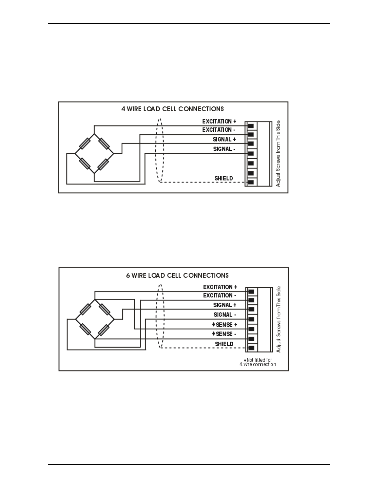
6.3. Load Cell Connection
The instrument may be connected for either 4-wire or 6-wire
operation. For more information, refer to BUILD:CABLE
setting page 19.
Quick Start Manual Rev 1.33
Page 8 003X-608-133
6.3.1. 4-Wire Connection
The minimum connectivity requirements are the connection of
four wires (ie. Excitation + and – along with Signal + and –).
The BUILD:CABLE option must be set to 4 to allow for 4-wire
connection.
6.3.2. 6-Wire Connection
The excitation and signal lines are connected the same as for
a 4-wire installation.
The BUILD:CABLE option must be set to 6 (the default) to
allow for 6-wire connection.
Quick Start Manual Rev 1.33
003X-608-133 Page 9
6.4. Auxiliary Connections
This section provides diagrams to illustrate the terminal
connections.
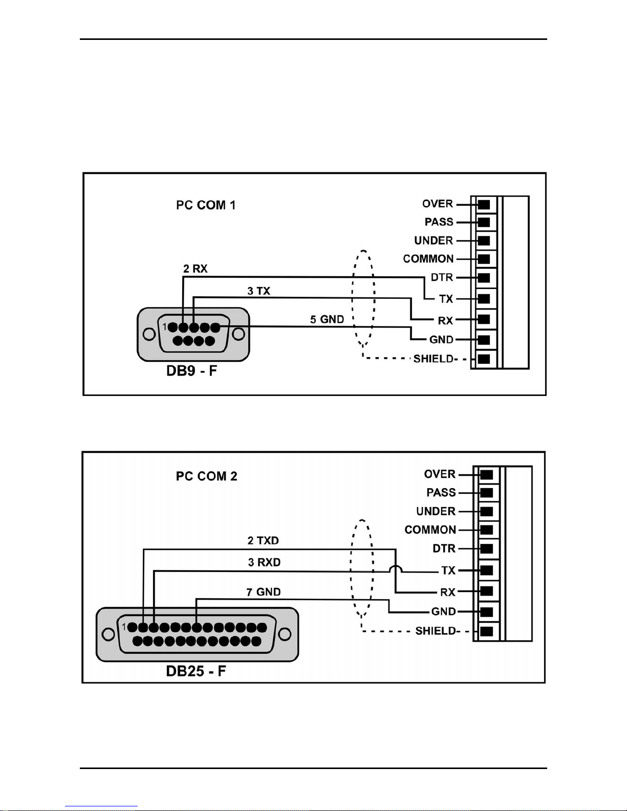
6.4.1. RS-232 Serial to PC
Network: One Instrument to PC (DB9) (RXD, TXD, GND)
Network: One Instrument to PC (DB25) (RXD, TXD, GND)
 Loading...