

CAS WTM Series, WTM-200, WTM-500 Service Manual

Service Manual
– WTM
REV NO
:
V1.1
WTM Series
(Weight Transmitter)
Service Manual
LAST Rev. NO : V1.1
LAST Rev. Date : 2015. 04. 20

Service Manual
– WTM
REV NO
:
V1.1
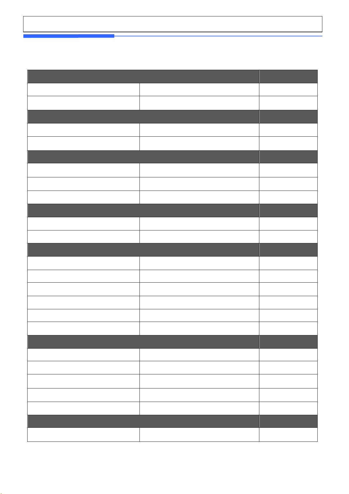
Table of Contents
1. Cautions for Your Safety ................................................................................................................................... 3
2. User Wanring ...................................................................................................................................................... 6
3. Features .............................................................................................................................................................. 7
4. Overview ............................................................................................................................................................. 9
5. External Dimension .......................................................................................................................................... 10
6. Installation & Connection ................................................................................................................................ 12
7. Weight Setup (Calibration) Mode .................................................................................................................... 13
8. How to Seal the Indicator (Sealing) ................................................................................................................ 25
9. Installing Options .............................................................................................................................................. 26
10. Interface ......................................................................................................................................................... 27
11. F.W Update Method ....................................................................................................................................... 28
11.1. Enter the F.W update mode(WTM-200) ............................................................................................. 28
11.2. Enter the F.W update mode(WTM-500) ............................................................................................. 28
11.3. F.W update method ............................................................................................................................... 29
12. Exploded Views.............................................................................................................................................. 31
12.1. Exploded view ...................................................................................................................................... 31
13. Partlist ............................................................................................................................................................ 32
13.1. Electronics Parts .................................................................................................................................. 32
13.2. Mechanism Parts .................................................................................................................................. 34
14. Block Diagram ................................................................................................................................................ 35
15. Revision .......................................................................................................................................................... 36
Service Manual
– WTM
REV NO
:
V1.1
1. Cautions for Your Safety
‘ Please comply with 'Cautions for Your Safety', which will lead you to use the product
safely and properly to prevent any dangerous situations.
■ Cautions are divided into 'Warning' and 'Alert', which mean as follows.
■ Keep this manual in a place where product users can find out, after finish reading it.
'Warning' means a great possibility led to the death or heavy injury when instructions are
violated.
'Alert' means a great possibility led to the injury or material damage when instructions
are violated.
Service Manual
– WTM
REV NO
:
V1.1
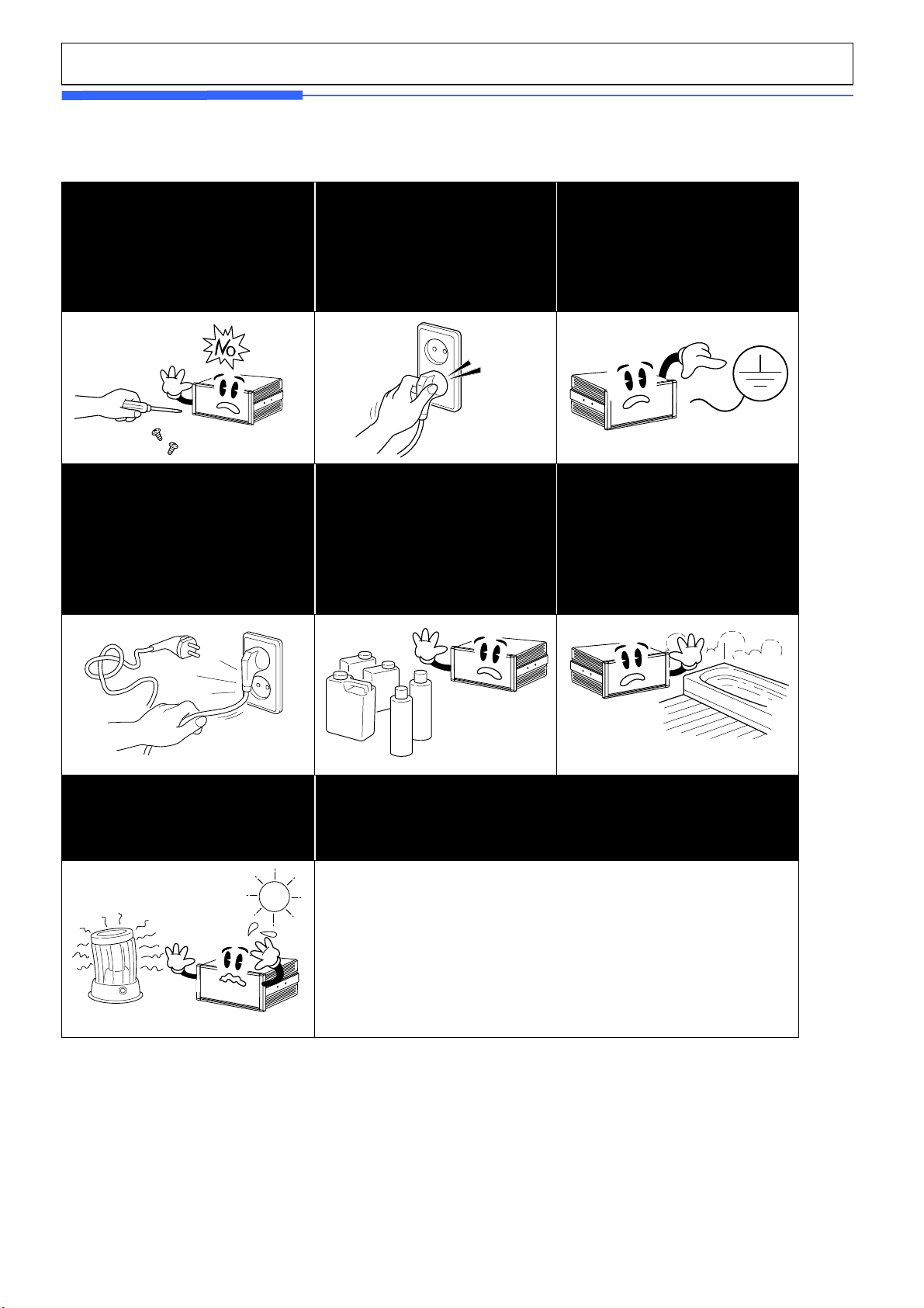
Never disassemble, repair or
from the quality assurance and
cause the damage to devices,
the power plug to be
Any instable connection might
Ensure the grounding of the
Poor grounding might cause
failure or electric shock upon
Keep any combustible spray or
Do not spray water to the outside
It might deteriorate the insulation
electric parts that can cause
retrofit the product.
It might exclude the product
Warning
Ensure
fully
inserted to prevent shaking.
product.
electric shock or fire.
Do not damage, process,
excessively jerk, bend or twist the
power cord.
It might damage the power cord to
cause fire or electric shock.
cause electric sparks to set fire.
fire source away.
It might cause fire.
electric leak.
of the product or use it in any
humid place.
of
the electric shock, fire risk or
weighing errors.
Do not place the product to the
direct sunlight or near any hot
object like a heater.
It might cause fire.
Service Manual
– WTM
REV NO
:
V1.1
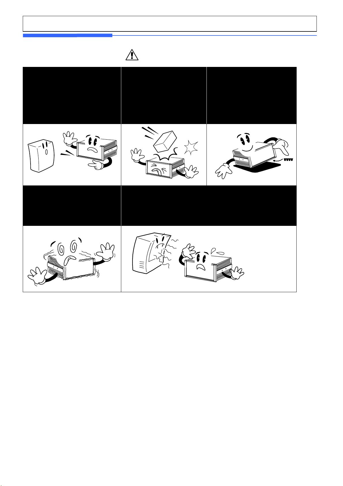
Check the weighing error anytime
Any use out of the allowed tolerance
for the careless use or other causes
might not ensure the accurate
Find a proper place to attach the
rubber pad at the bottom of the
indicator, which was shipped
Do not use the product at a place
Do not install the produce at a place with the excessive
Attention
for the accurate weighing.
weighing.
Customer Service:080-022-0022
Avoid any sudden shock to the
product.
It might damage the product to
fail the accurate weighing.
together.
with sudden temperature changes or
severe vibrations.
It might cause the weighing error or
failure.
electromagnetic wave.
It might cause the wrong weighing.
Our Dealers : CAS feels that each of its valued customers should get the best service
available. Whether it’s the initial installation of our product,
maintenance/repair work, or simply answering questions about our
products, CAS Corporation and all of its Authorized Dealers are highly
trained to assist
you with any need regarding CAS products.

Service Manual
– WTM
REV NO
:
V1.1
2. User Wanring
Recommendations for the proper use of weighing instruments
- Keep away from heat sources and direct sunlight
- Repair the instrument from rain(except special IP versions)
- Do not wash with water jet(except special IP versions)
- Do not dip in water
- Do not spill liquid on the instrument
- Do not use solvents to clean the instrument
- Do not install in areas subject to explosion hazard(except special Atex versions)
Recommendations for correct installation of weighing instruments
The terminals indicated on the instrument’s wiring diagram to be connected to earth
must have the same potential as the weighed structure (same earthing pit or earthing
system). If you are unable to ensure this condition, connect with an earthing wire the
terminals of the instrument (including the terminal 0VDC) to the weighed structure.
The cell cable must be individually led to its panel input and not share a conduit with other
cables; connect it directly to the instrument terminal strip without breaking its route with
support terminal strips.
Use “RC” filters on the instrument-driven solenoid valve and remote control switch coils.
Avoid inverters in the instrument panel; if inevitable, use special filters for the inverters
and separate them with sheet metal partitions.
The panel installer must provide electric protections for the instruments (fuses, door lock
switch etc.).
It is advisable to leave the equipment always switched on to prevent the formation of
condensation.
MAXIMUM CABLE LENGTHS
- RS485: 1000 metres with AWG24, shielded and twisted cables
- RS232: 15 metres for baud rates up to 19200
Service Manual
– WTM
REV NO
:
V1.1
3. Features
Power supply voltage 10 ~ 24 V
Max consumption 70 with 350 Ω mA
Power supply Unit
Temperature range
Storage temperature -25 ~ 85
Operating temperature -10 ~ 40
Loadcell
Impedance(complete bridge) > 80 Ω
Connection 4 or 6 wires
Loadcell power supply
Communication
RS485 Half duplex
Baud rate 9600 ~ 115200 BPS
Logical inputs
Numbers 2
type Optocoupler
5 ± 5 %
℃
℃
Vdc
Low level voltage 0 ~ 3 Vdc
Higi level voltage 9 ~ 24 Vdc
Current at high level 10 mA @ 24 V mA
Insulation voltage 2500 Vrms
Logical outputs
Numbers 4
type
Max current @ 40℃
Max voltage in open state 2 Ω
Insulation voltage 2500 Vrms
Legal for use metrological characteristics
Class III or IIII

Service Manual
– WTM
REV NO
:
V1.1
Minimum voltage division per
verification scale division
Maximum voltage for weighing range
Programmable functions
Acquisition of zero, taring, zero tracking
Physical or theoretical calibration
Non-linearity polynomial correction
Low pass, band-stop and self-adaptive digital filters
Set points managements
Checkweigher functioning mode
Peak detection functioning mode
Display 7 Segment LED, 4 key
0.5 uV
39 mV
Slope correction
Option
A-Out V-out, I-out
Relay I/O 2input, 4output
Alibi memory
Ethernet 10/100 M
Fieldbus Profibus
50,000개 Save
Real time clock
-10 V~10 V
0~24 mA
Service Manual
– WTM
REV NO
:
V1.1
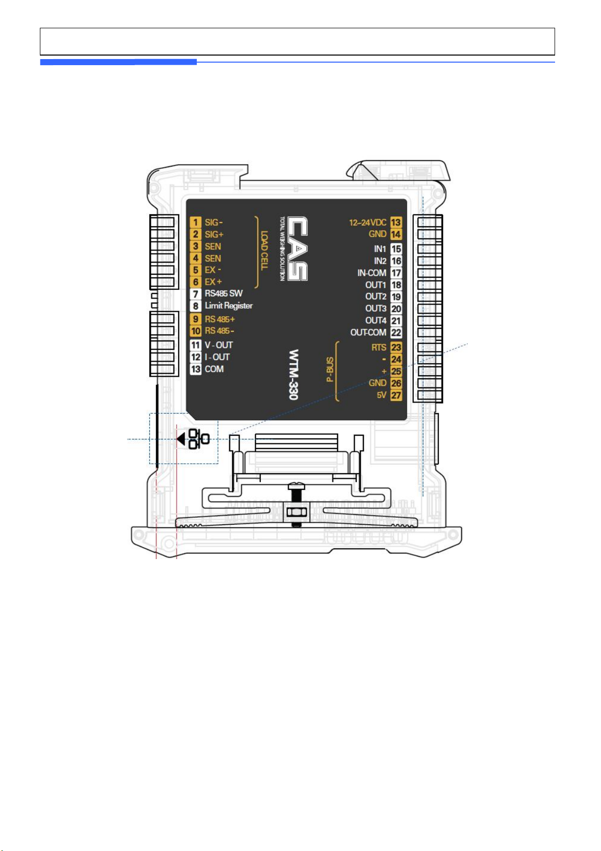
4. Overview
Service Manual
– WTM
REV NO
:
V1.1
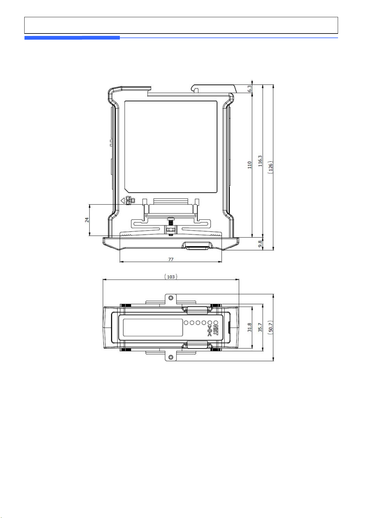
5. External Dimension
1. Weight : 6Digits, Decimal point, sign
2. Unit : ton, kg, lb
3. Message : Displayed of indicator’s status
Ext Output are 4
Ext Inputs are 2
Service Manual
– WTM
REV NO
:
V1.1
0
Zero
LED
LED
ON : output 3 Closed
■ Display
LED Main function Sub function
NET
On = Net , Off = Gross LED ON : output 4 Closed
Stable LED LED ON : output 2 Closed
t
kg
L
Unit : ton LED ON : output 1 Closed
Unit : kg LED ON : input 2 Closed
Unit : lb LED ON : input 1 Closed
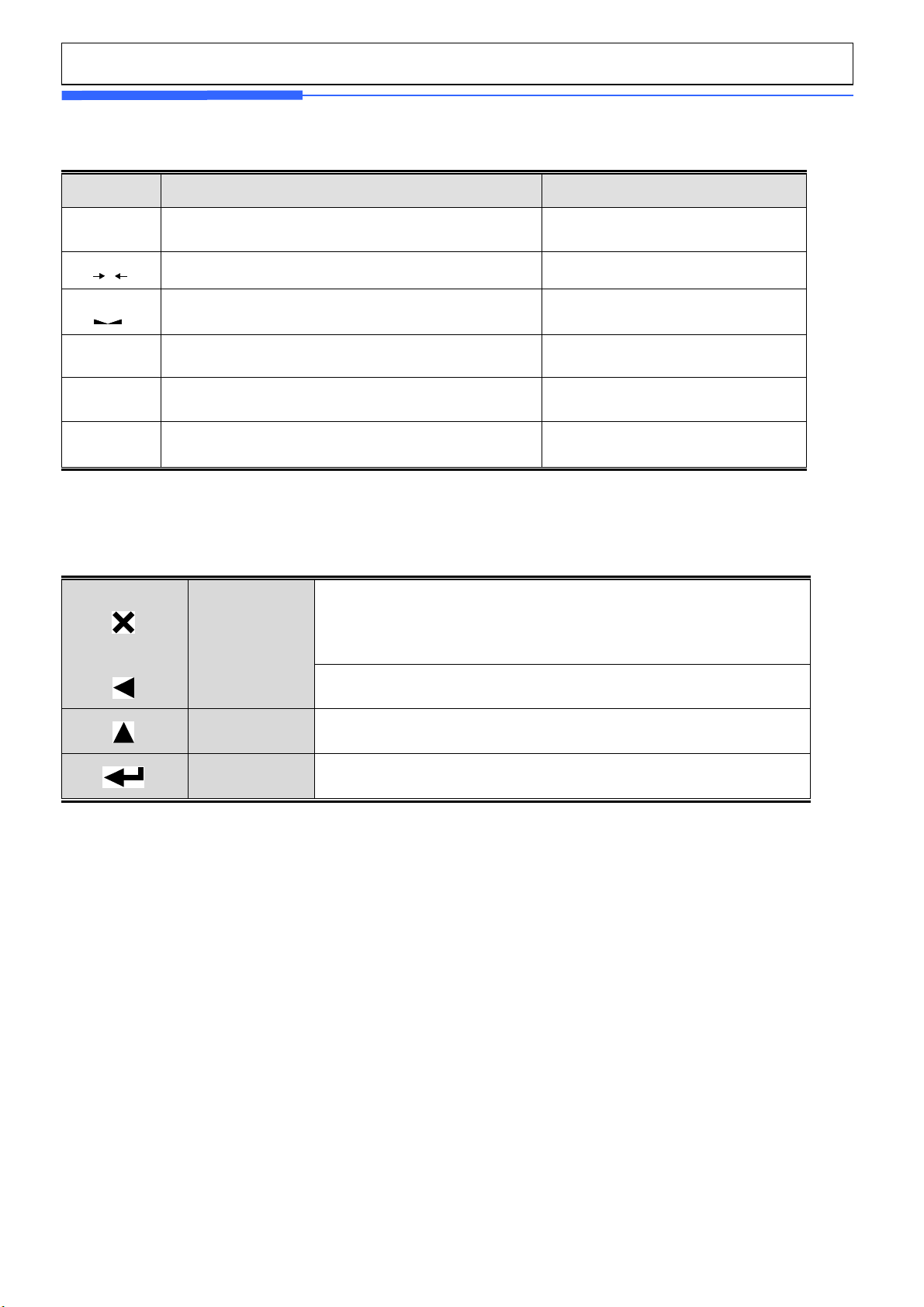
■ Key function
ESC
* It sets the weight display near zero point to 0.
( A range of 2%, 5%, 10%, 20% and 100% can be
selected.)
LEFT
HI
ENTER
* Use it change to item number
* Some functions can be defined to the needs.
* Use it enter to menu mode.
 Loading...