

CAS SW-1S, SW-1W, SW-1C Service Manual

SW-1S/1C/1W Service
Manual
1 2/28/2011
SW-1S/1C/1W SERVICE MANUAL
(Revision 0.1 / 2008.06.17)

SW-1S/1C/1W Service
Manual
2 2/28/2011
< Table of Contents >
1. Introduction ............................................................................................................................... 3
1.1. Preface .................................................................................................................................... 3
1.2. Precaution ............................................................................................................................. 3
1.3. Specifications ...................................................................................................................... 4
1.4. Key ............................................................................................................................................. 6
1.5. Dimension .............................................................................................................................. 6
1.6. Sealing Method ................................................................................................................... 8
2. Calibration ................................................................................................................................. 10
2.1. General Calibration ........................................................................................................ 10
2.1.1. C4 Setting ........................................................................................................... 11
2.1.1.1. C4-1 Setting ................................................................. 11
2.1.1.2. C4-3 Setting ................................................................. 11
2.1.2. SPAN Calibration Setting (C-3) .............................................................. 12
2.1.3. Gravity Constant Value Setting (C-9) ................................................ 12
2.1.4. Calibration factor Setting (C-10) .......................................................... 13
2.1.5. Displaying Real A/D Value (C-5) .......................................................... 13
2.1.6. Percent Calibration (C-7) .......................................................................... 14
2.1.7. Battery Calibration (C-8) ........................................................................... 14
3. The Schematics and Diagram ......................................................................................... 15
3.1. System Block Diagram ................................................................................................. 15
3.2. Circuit Diagram ................................................................................................................ 16
3.2.1. Main PCB .............................................................................................................. 16
3.2.2. Power Part (Main PCB) .................................... Error! Bookmark not defined.
3.2.3. Rear Display PCB ............................................................................................ 17
4. Exploded View ......................................................................................................................... 18
5. Load Cell drawing .................................................................................................................. 20
6. Part Location ............................................................................................................................ 21
6.1. Main PCB (Top) ................................................................................................................ 21
6.2. Main PCB (Bottom) ........................................................................................................ 22
6.3. Rear Display PCB (Top) ............................................................................................... 23
7. Error Messages & Solution............................................................................................... 24
8. Part List ....................................................................................................................................... 25

SW-1S/1C/1W Service
Manual
3 2/28/2011
1. Introduction
1.1. Preface
Thank you for purchasing of our CAS scale.
This scale has been designed with CAS reliability, under rigid quality control
and with outstanding performance.
WE hope that your departments enjoy with high quality of CAS product.
This manual will help you with proper operations and care of the SW-1S/1C/1W series.
Please keep it handy for the future references.
1.2. Precaution
Make sure that you plug your scale into the proper power outlet.
Place the scale on a flat and stable surface.
Plug into a power outlet 30 minutes before operations.
Keep the scale away from strong EMI noises may cause incorrect weight readings.
This scale must be installed in a dry and liquid free environment.
Do not subject the scale to sudden temperature changes.
Do not subject the platter to sudden shocks.
If the scale is not properly level, please adjust the 4 legs at the bottom of the
scale (turn legs clockwise or counterclockwise) so as to center the bubble of the
leveling gauge inside the indicated circle.
SW-1S/1C/1W Service Manual
4 2/28/2011
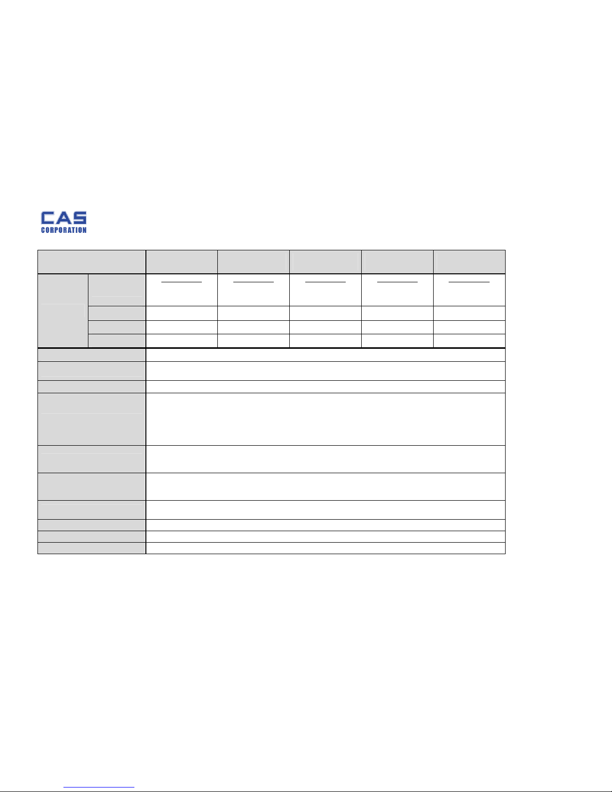
1.3. Specifications
SW-1S/1C/1W-
02
SW-1S/1C/1W-
05
SW-1S/1C/1W-
10
SW-1S/1C/1W-
20
SW-1S/1C/1W-
30
Resolution
Capacity / e
Dual Interval
1 kg / 0.0005 kg
2 kg / 0.001 kg
Dual Interval
2.5 kg / 0.001 kg
5 kg / 0.002 kg
Dual Interval
4 kg / 0.002 kg
10 kg / 0.005 kg
Dual Interval
10 kg / 0.005 kg
20 kg / 0.01 kg
Dual Interval
15 kg / 0.005 kg
30 kg/ 0.01kg
Internal
1 / 60,000 1 / 60,000 1 / 60,000 1 / 60,000 1/60,000
External
1 / 2,000 1 / 2,500 1 / 2,000 1 / 2,000 1 / 3,000
Max. Tare
- 0.9995 kg - 2.449 kg - 3.998 kg - 9.995 kg - 14.995 kg
Display
110 x 35[mm]/43" x 13.8" 5 digit LCD
Indicators
STABLE, ZERO, TARE, g, kg, lb, oz, Low Battery
HI / OK / LO & PCS (SW-1C only)
Keys
ZERO, TARE, HOLD(Hold Ver.), UNIT(Unit Ver.), MODE(SW1C), POWER
Functions
Weighing, WaterProof level IP66(SW-1W only)
Hold(Hold Ver . ), Unit Conversion(Unit Ver.),
Counting-Counting SampleRange :
10~100,200,300,400,500 (SW-1C only)
Weight Comparison Function : hi, ok, low(SW-1C only)
Sleep Mode Function
Dimension
260(W) x 287(D) x 137(H)[mm] / 102(W) x 113(D) x 54(H)[inch]
278(W) x 317(D) x 141(H)[mm] / 109(W) x 125(D) x 56(H)[inch]
(SW-1W : WaterProof Type)
Platter Size
230(W) x 190(D)[mm] / 90.55(W) x 74.80(D)[inch]
247(W) x 195(D)[mm] / 97.24(W) x 76.77(D)[inch]
(SW-1W : WaterProof Type)
Weight
2.8kg
3.7kg(SW-1W : WaterProof Type)
Power
1.5V x 6 units (D size Battery) or 9V Adapter
Op.Temperature
-10°C ~ +40°C / 14°F ~ 104°F
Options
9V Adapter 300mA, Rear Display, Stainless Tray (SW-1S, SW-1C)
SW-1S/1C/1W Service Manual
5 2/28/2011
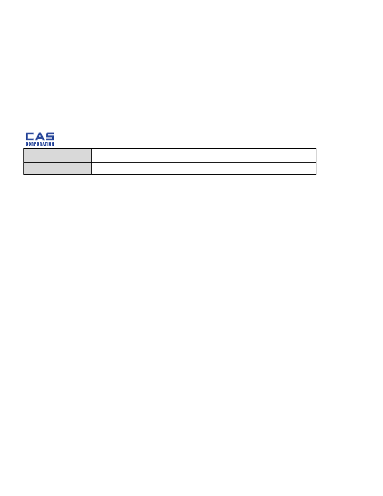
Minimum Voltage
Level The Battery
About 5.5V
Operation time
Approx. 500hours (Manganese battery)/
1000hours (Alkaline at 20°C /68°F)
SW-1S/1C/1W Service
Manual
6 2/28/2011
1.4. Key
Key Function
ZERO (-O-)
[Set]
To set zero point
To do [SET] key in th e SETUP mode.
TARE
To input or cancel the tare (the weight of container).
HOLD
To make the we ight of item stable. This weight is average value.
POWER
To turn on or off.
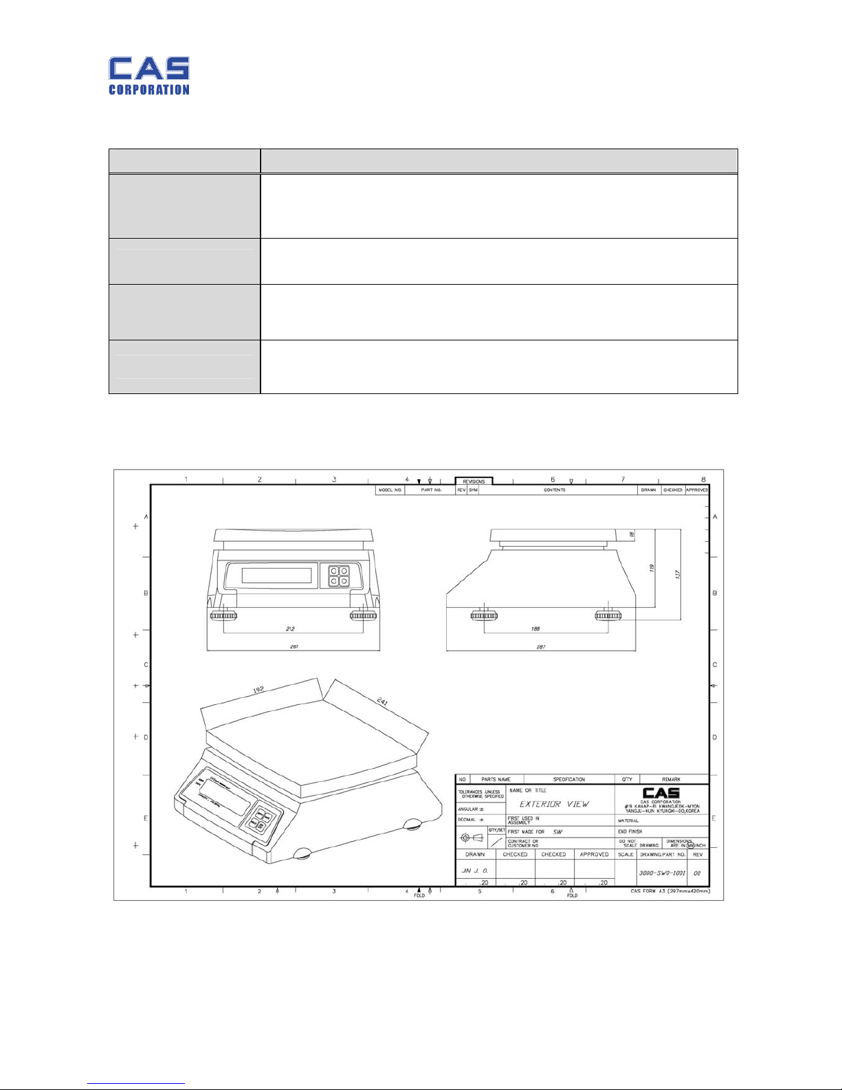
1.5. Dimension
1.5.1. SW-1S/1C
SW-1S/1C/1W Service
Manual
7 2/28/2011
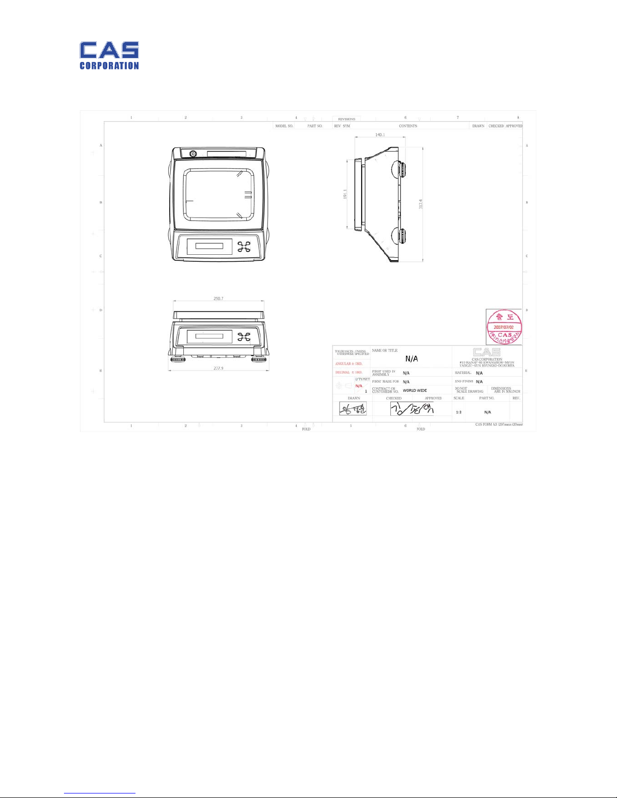
1.5.2. SW-1W
SW-1S/1C/1W Service
Manual
8 2/28/2011
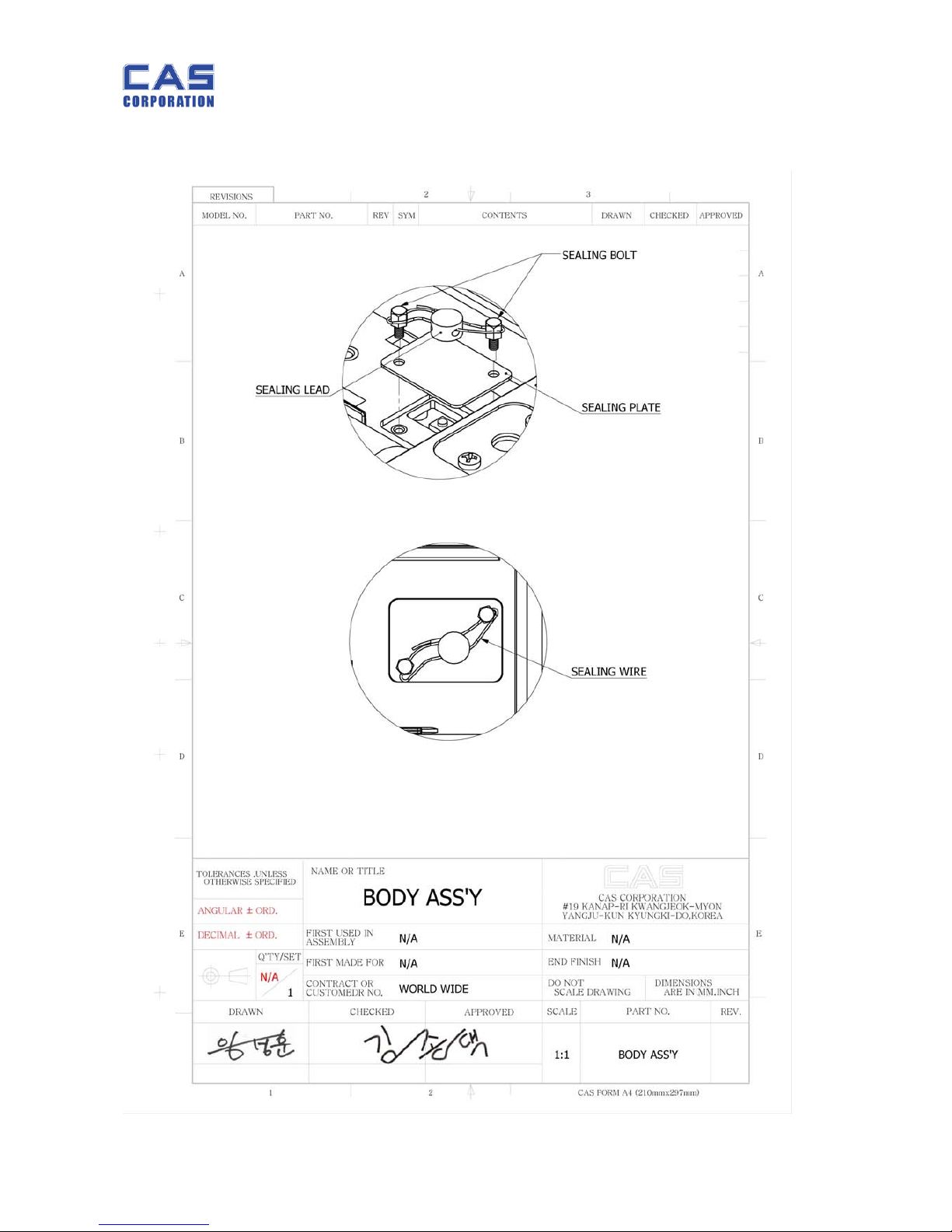
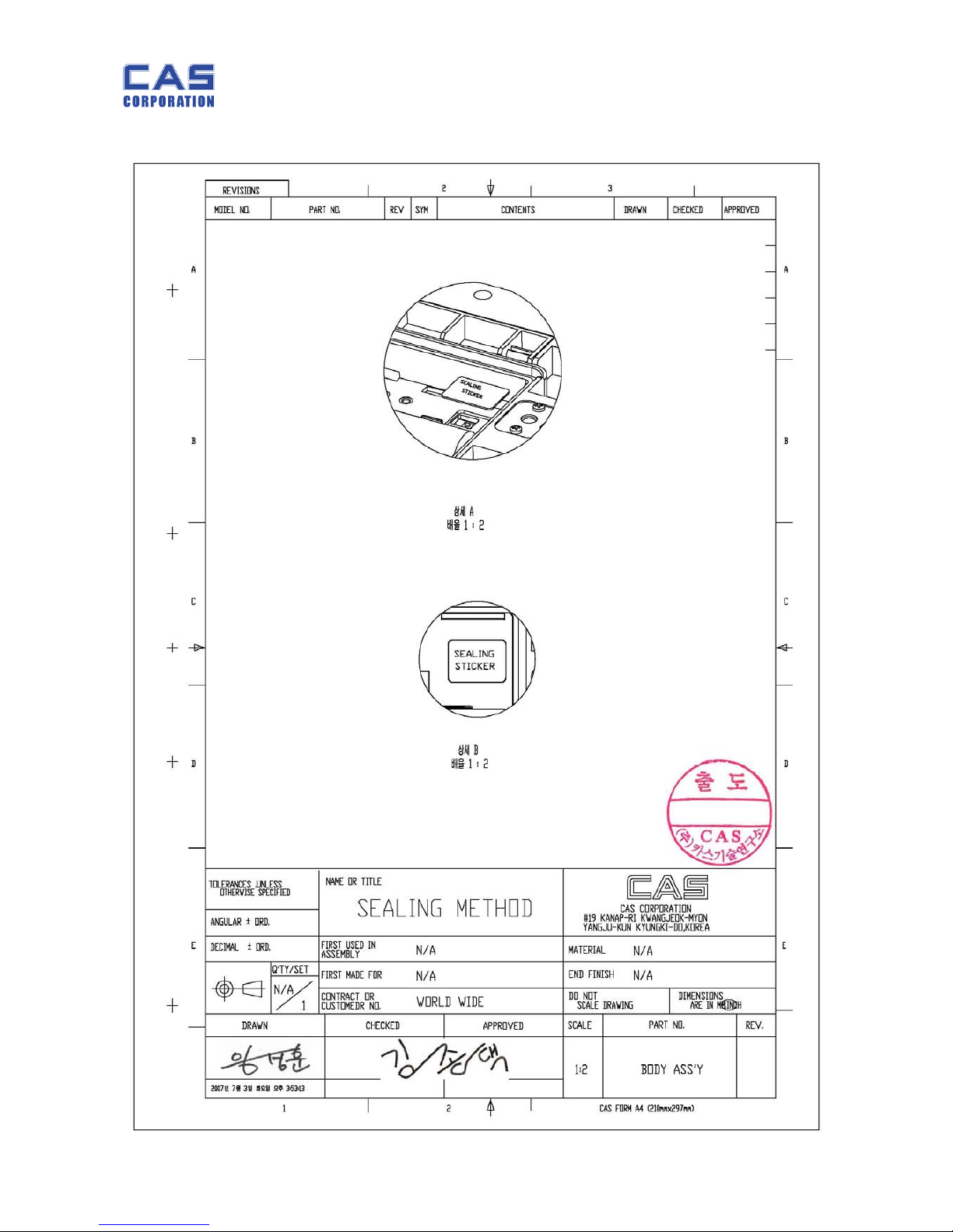
1.6. Sealing Method
SW-1S/1C/1W Service
Manual
9 2/28/2011
SW-1S/1C/1W Service
Manual
10 2/28/2011
2. Calibration
2.1. General Calibration
Pressing and holding calibration switch press [POWER] key to go to calibration mode.
User can move to other mode by using [ZERO] key in the calibration mode.
User also moves to other sub-modes for each mode by using [TARE] key.
Please simply follow below procedure to move to other mode.
Calibration Mode: Pressing and holding “Calibration Switch” press [POWER] key.
It displays “CAL-0” after “CAL”, and it blinks the version of scale three times.
Selecting menu: press [TARE].
ENTER(Setting) : [TARE] key
MODE Function
CAL 1
Display normalized AD
CAL 2
Display Keypad infomation-
CAL 3
Calibration
‘Zero’ key to select
‘ZERO’ ‘Zero’ key to proceed
‘Midup’ (Refer to table in 2.1.2. C-3) ‘Zero’ key to proceed
‘Full’ Full weight ‘Zero’ key to proceed
‘Middn’ (Refer to table in 2.1.2. C-3), ‘Zero’ key to proceed
CAL 4
Option Setting ( Refer to Table 1)
CAL 5
Display filtered Raw AD
CAL 7
% Calibration
CAL 8
Battery calibration
CAL 9
Gravity constant
CAL 10
Set calibration factor
Refer to 2. 1. 4
CAL 11
Set nation(00 : OIML , 01 : NTEP , 02: KOREA)
SW-1S/1C/1W Service
Manual
11 2/28/2011
< Modes >
2.1.1. C4 Setting
2.1.1.1. C4-1 Setting
BIT 6~7 Initial Zero range
3 5%
2 10%
1 3%
0 2%
BIT5 Last digit enable
0 Disable
1 Enable
BIT4 Key zero percent
0
±3% key zero percent
1
±2% key zero percent
BIT 2~3 Successive tare
3 (+), (-) All Direction successive Tare
2 (+) Direction successive Tare
1 (-) Direction successive Tare
0 One Time tare
BIT0~1 Zero mark type
0 Gross zero indication
1 Net zero indication
2 Both(gross and net) zero indication
2.1.1.2. C4-3 Setting
BIT7 Dot Type
0 "." dot
1 "," comma
BIT6 Use Preset tare
0 Don't use
1 Use
BIT5 Use Back light
0 Don't use
1 Use
BIT4 Use Head message
0 Don't use
1 Use
BIT3 Use gram
0 Don't use
1 Use
BIT2 Use oz
0 Don't use
1 Use
BIT1 Use lb
0 Don't use
1 Use
BIT0 Use Kg
0 Don't use
1 Use

SW-1S/1C/1W Service
Manual
12 2/28/2011
2.1.2. SPAN Calibration Setting (C-3)
Pressing and holding “Calibration Switch” press [POWER] key.
After “CAL” message blinks three times and shows the version of scale, it displays “CAL
1” message.
Press [Tare] / [Mode] to display “CAL-3”.
Press [Zero] key and then it displays “zero” message.
Press [Zero] key and then it displays “midup” message
Load middle up weight (Refer to table below) on the platform
Press [Zero] key and then it displays “FULL ” message
Load full weight on the platform
Press [Zero] key and then it displays “middn” message
Load middle down weight (Refer to table below) on the platform
Press [Zero] key and then it display “CAL 3” message
Press [Power] key to save & switch off
Table for Cal weights
Full Half weight
20 10
10 5
5 2
2 1
2.1.3. Gravity Constant Value Setting (C-9)
Current gravitational Acceleration value is set to 9.7994 m/s2 .
Pressing and holding “Calibration Switch” press [POWER] key.
After “CAL” message blinks three times and shows the version of scale, it displays “CAL-1” message.
Press [ZERO] to display “C-9”.
Press [TARE] key, and then “ G-1“ message and “9.7994” will be shown. The first digit,”9” will blink.
Input a gravitational acceleration value by using [ZERO] key.
Press [TARE] key, and then “G-2“ message blinks.“9.7994” will be shown. The first digit,”9” will blink.
Input a gravitational acceleration value by using [ZERO] key.
Press [TARE] key to save the gravitational acceleration value, and “C-9 ” message will be shown.

SW-1S/1C/1W Service
Manual
13 2/28/2011
2.1.4. Calibration factor Setting (C-10)
Pressing and holding “Calibration Switch” press [POWER] key.
After “CAL” message blinks three times and shows the version of scale, it displays
“CAL-1” message.
Press [MODE] or [TARE] to move to display “C-10”.
Press [ZERO] key, and then “UNIT “message and “0” will be shown. The first digit,”0”
will blink. It means calibration unit is “kg” (0 : kg, 1 : lb)
Input a calibration unit by using [MODE] key.
Press [ZERO] key and then “CAPA“message blinks. “0015” will be shown. The first
digit,”0” will blink. It means a full-capability is “15 (calibration unit, kg or lb)”
Input a capability by using [MODE] key to change value [TARE] key to move the right.
Press [ZERO] key, and then “MId“message blinks. “0005” will be shown. The first
digit,”0” will blink. It means a mid-capability is “05 (calibration unit, kg or lb)”
Input a capability by using [MODE] key to change value [TARE] key to move the right.
Press [ZERO] key, and then “W-dP “message blinks. “3” will be shown. The first
digit,”3” will blink. It means a weight decimal point is “3 (will display 0.000)”
Input a weight decimal point by using [MODE] key.
Press [ZERO] key, and then “1d “message blinks.“0.005” will be shown. The third
digit,”0” will blink. It means a division is “0.005 (calibration unit, kg or lb)”
Input a division by using [MODE] key to change value [TARE] key to move the right.
Press [ZERO] key, and then “dual “message blinks. “1” will be shown. The third
digit,”1” will blink. It means a dual interval is disable. (0 : disable, 1 : enable)”
Input a dual interval enable by using [MODE] key.
Press [ZERO] key, and then “TARE “message blinks. “0” will be shown. The third
digit,”1” will blink. It means a dual interval is disable. (0 : disable, 1 : enable)”
Press [ZERO] key to save the calibration factor and “C-10” message will be shown.
Turn off scale to save
2.1.5. Displaying Real A/D Value (C-5)
Display Raw AD
 Loading...