

Page 1

PW-II Service Manual
1
PW-II SERVICE MANUAL
Page 2

PW-II Service Manual
2
< Table of Contents >
1. Introduction ............................................................................................................................... 4
1.1. Preface................................................................................................................................... 4
1.2. Precaution............................................................................................................................ 4
1.3. Specifications..................................................................................................................... 5
1.3.1. PW-II Specifications ...................................................................................... 5
1.4. Key............................................................................................................................................ 6
1.5. Sealing Method ................................................................................................................. 7
2. Calibration................................................................................................................................... 8
2.1. General Calibration......................................................................................................... 8
2.1.1. C4 Setting ............................................................................................................. 9
2.1.1.1. C4-1 Setting................................................................................................. 9
2.1.1.2. C4-2 Setting................................................................................................. 9
2.1.1.3.
C4-3 Setting................................................................................................. 9
2.1.1.4. C4-4 Setting................................................................................................. 9
2.1.1.5. C4-5 & 4-6 Setting................................................................................. 10
2.1.2. SPAN Calibration Setting (C-3).............................................................. 10
2.1.3. Gravity Constant Value Setting (C-9) ................................................ 11
2.1.4. Displaying Real A/D Value (C-5).......................................................... 11
2.1.5. How to confirm SPAN calibrated A/D value (C-1) ..................... 12
2.1.6. Back to the normal weighing mode (C-0)....................................... 12
2.1.7. Calibration Block Diagram........................................................................ 13
3. The Schematics and Diagram......................................................................................... 14
3.1. System Block Diagram................................................................................................ 14
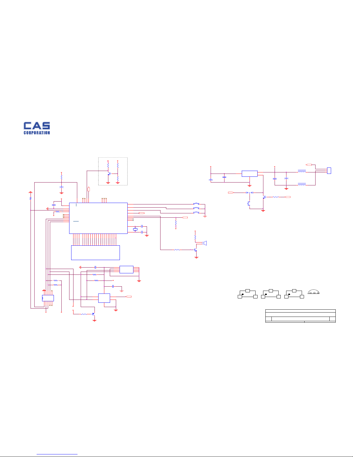
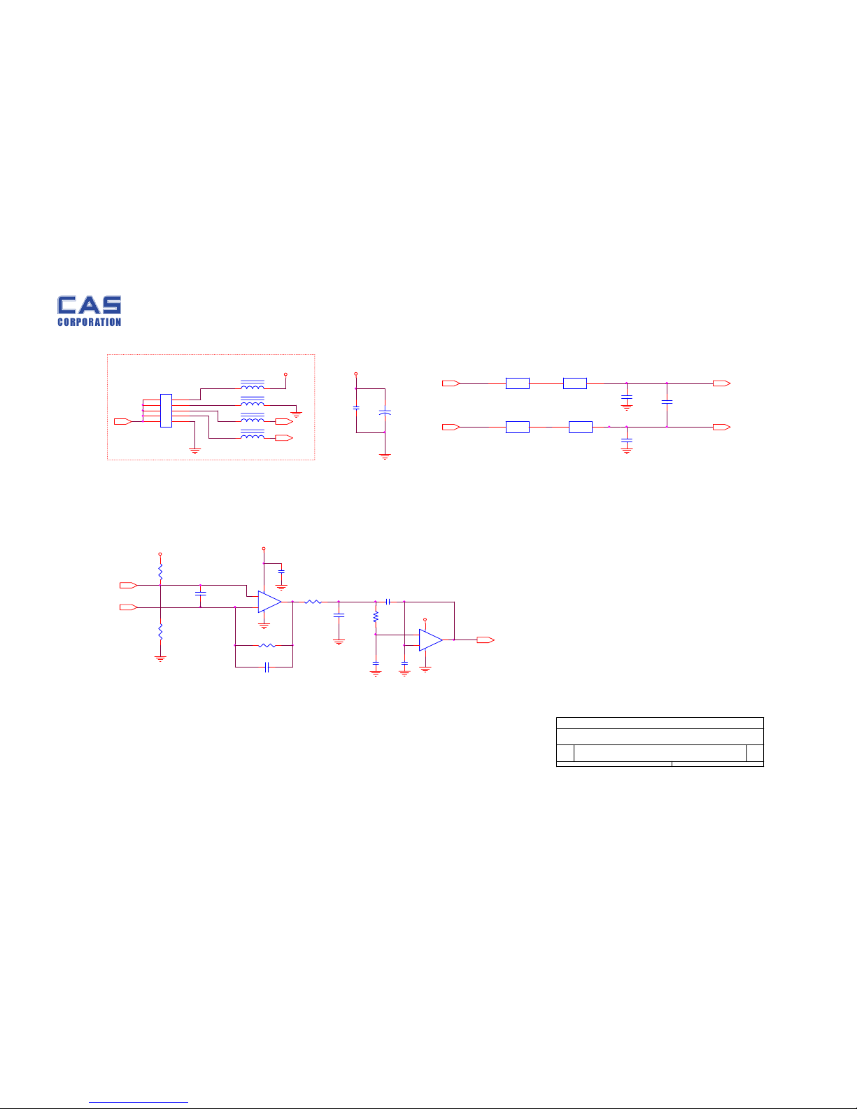
3.2. Circuit Diagram............................................................................................................... 15
3.2.1. Main........................................................................................................................ 15
3.2.2. A/D ......................................................................................................................... 16
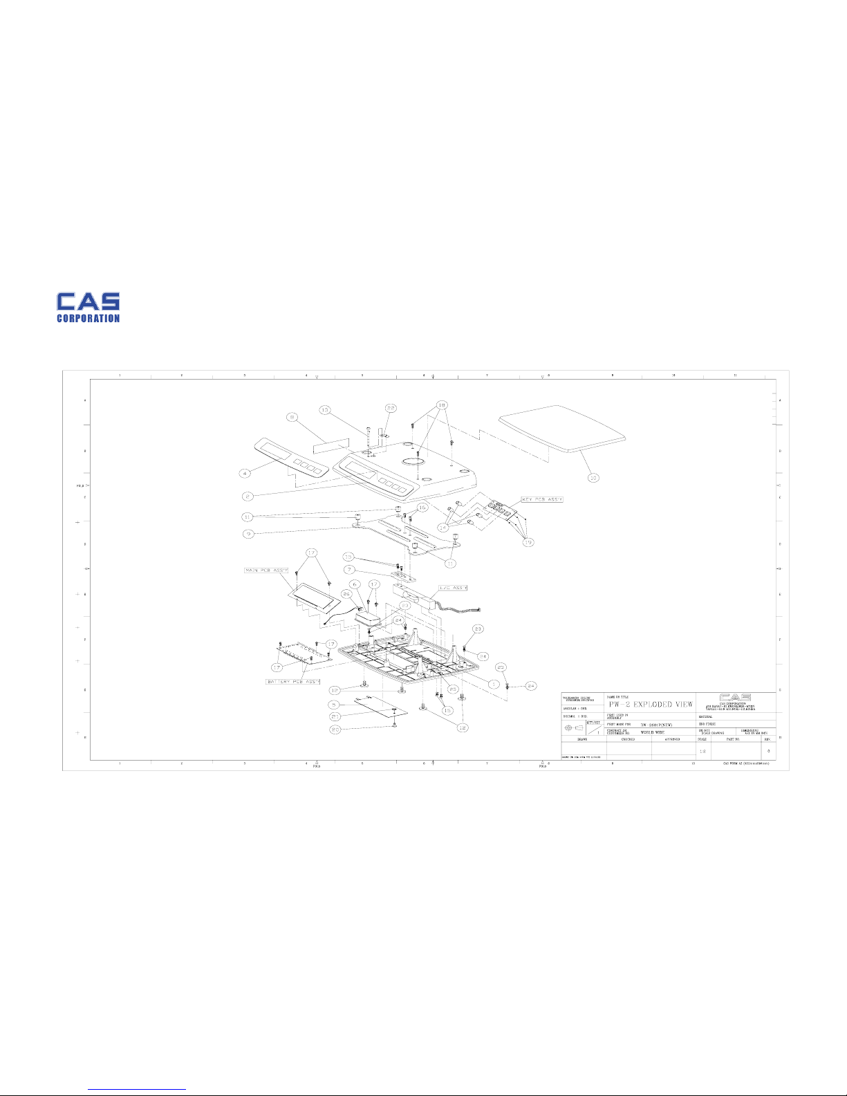
4. Exploded View......................................................................................................................... 17
Page 3

PW-II Service Manual
3
5. Part Location............................................................................................................................18
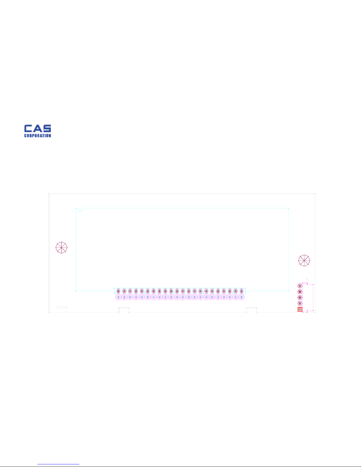
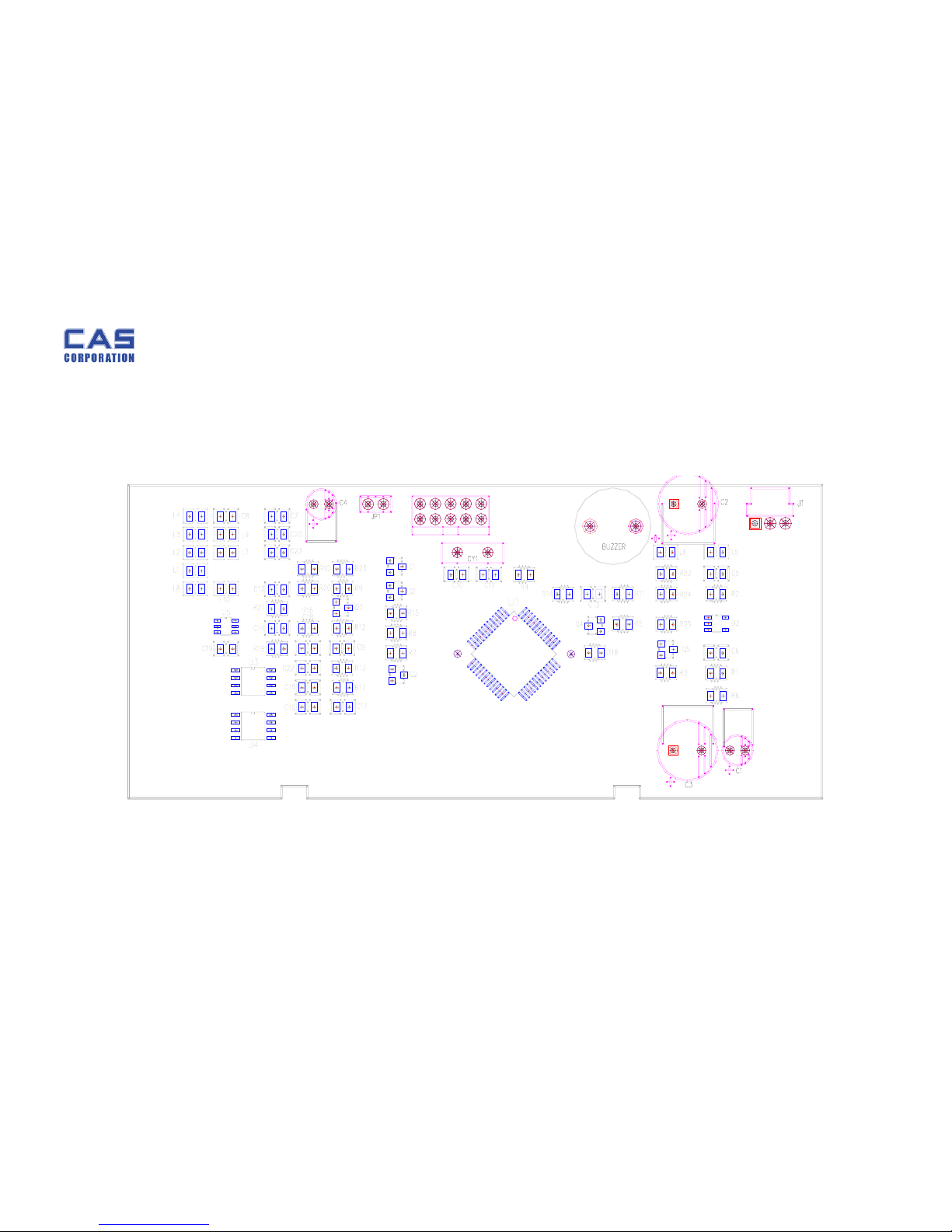
5.1. Main PCB (Front) ........................................................................................................... 18
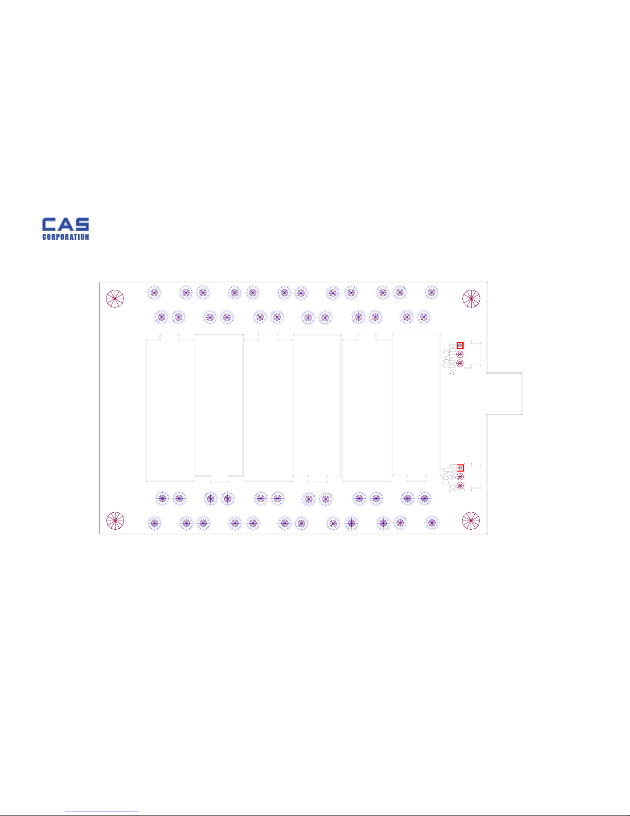
5.2. Main PCB (Rear)............................................................................................................. 19
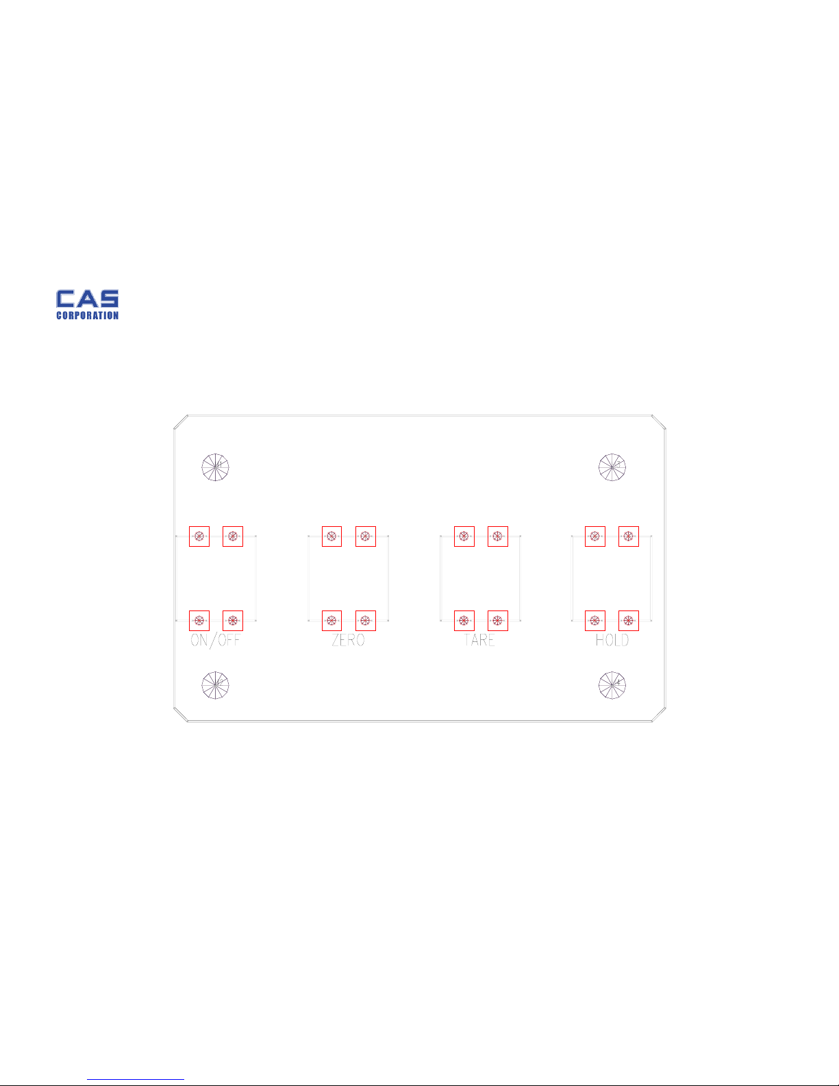
5.3. Battery PCB....................................................................................................................... 20
5.4.
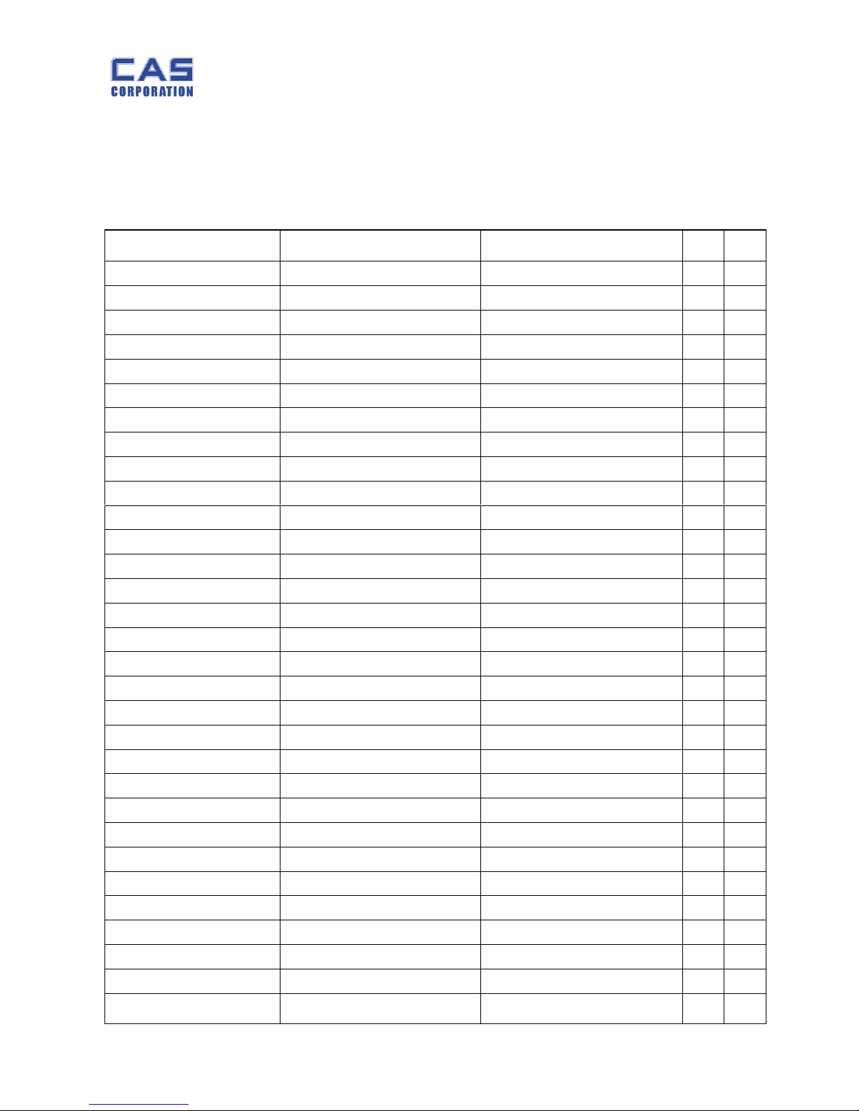
Key PCB ............................................................................................................................. 201
6. Partlist......................................................................................................................................... 22
6.1.
Circuit Part .................................................................................. 22
6.1.1. Main PCB Ass'y....................................................................22
6.1.2. Battery PCB Ass'y................................................................23
6.1.3. Key PCB Ass'Y………………………………………………………………23
6.2.
Mechanism Part ........................................................................... 24
6.2.1. Body Ass'y...........................................................................24
6.2.2. C/T Box Ass'y......................................................................25
6.2.3. Loadcell Ass'y………………………………………………………………25
7. Error Message & Solution…………………………………………………………...26
7.1. Beep : Re-zero…...........................................................................26
7.2. Err : Initial zero…………………………………………………………………….26
7.3 Init : Failure of Analog Module……………………………………………….26
7.4 UNSTA : A/D Value Unstable………………………………………………….26
Page 4

PW-II Service Manual
4
1. Introduction
1.1. Preface
Thank you for purchasing of our CAS scale.
This scale has been designed with CAS reliability, under rigid quality control
and with outstanding performance.
WE hope that your departments enjoy with high quality of CAS product.
This manu a l will help you with proper operations and care of the PW series.
Please keep it handy for the future references.
1.2. Precaution
• Make sure that you plug your scale into the proper power outlet.
• Place the scale on a flat and stable surface.
• Plug into a power outlet 30 minutes before operations.
• Keep the scale away from strong EMI noises may cause incorrect weight readings.
• This scale must be installed in a dry and liquid free environment.
• Do not subject the scale to sudden temperature changes.
• Do not subject the platter to sudden shocks.
• If the scale is not properly level, please adjust the 4 legs at the bottom of the
scale (turn legs clockwise or counterclockwise) so as to center the bubble of the
leveling gauge inside the indicated circle.
Page 5
PW-II Service Manual
5
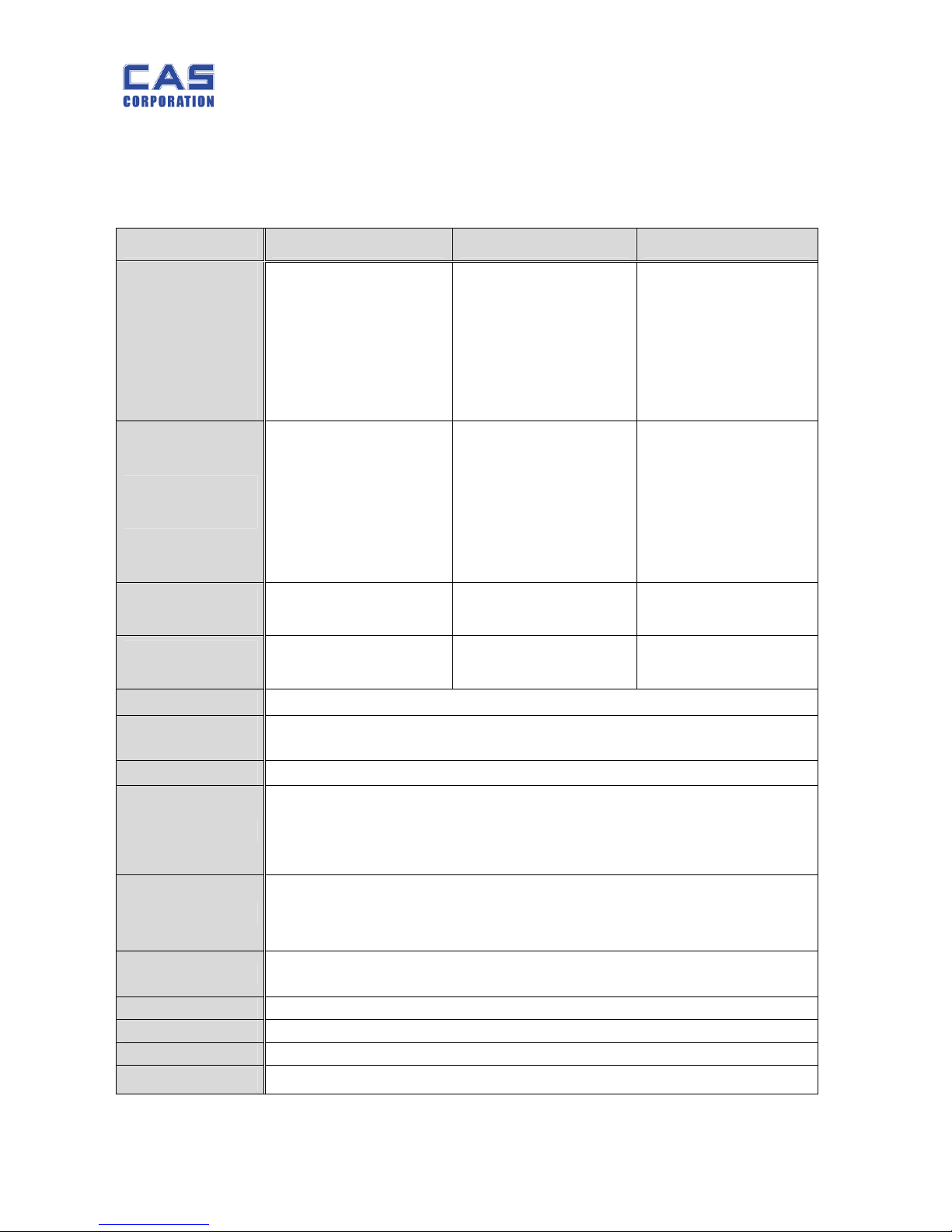
1.3. Specifications
1.3.1. PW-II Specifications
PW-II(2kg) PW-II(5kg) PW-II(10kg)
Capacity / e
Low
Resolution
2,000g / 1 g
(2 kg / 0.001 kg)
5 lb / 0.002 lb
80 oz / 0.05 oz
5,000g / 2 g
(5 kg / 0.002 kg)
10 lb / 0.005 lb
160 oz / 0.1 oz
10,000g / 5 g
(10 kg / 0.005 kg)
20 lb / 0.01 lb
400 oz / 0.2 oz
High
Resolution
2,000.0g / 0.5 g
2 kg / 0.0005 kg
(1/4,000)
5 lb / 0.001 lb
(1/5,000)
80 oz / 0.02 oz
(1/4,000)
5,000.0g / 1 g
5 kg / 0.001 kg
10 lb / 0.002 lb
(1/5,000)
160 oz / 0.05 oz
(1/3,200)
10,000g / 2 g
10 kg / 0.002 kg
(1/5,000)
20 lb / 0.005 lb
400 oz / 0.1 oz
(1/4,000)
Internal
Resolution
1 / 20,000 1 / 25,000 1 / 20,000
External
Resolution
1 / 2,000 1 / 2,500 1 / 2,000
Display 91 X 39 [mm] / 3.6 X 1.5 [inch] 5 digits LCD
Symbols
(Indicators)
STABLE, ZERO, TARE, g, kg, lb, oz, Low Battery
HI/OK/LO, PCS
Keys ZERO, TARE, HOLD, UNIT, POWER
Functions
• Simple Weighing function
• Hold function
• Weight Unit Conversion Function (g/kg/lb/oz)
• Auto Power Off
Dimension
239(Width) × 227(Depth) × 66(Height) [mm] /
9.4(Width) × 8.9(Depth) × 2.6(Height) [inch]
Platter Size
222(Width) × 151(Depth) [mm]/
8.7(Width) × 5.9(Depth) [inch]
Weight 1.5 kg
Power 1.5V x 6 (AA size battery) or 9 V Adaptor
Op.Temperature - 10 °C ~ +40 °C
Op. Power 9V/300mA Adaptor
Page 6
PW-II Service Manual
6
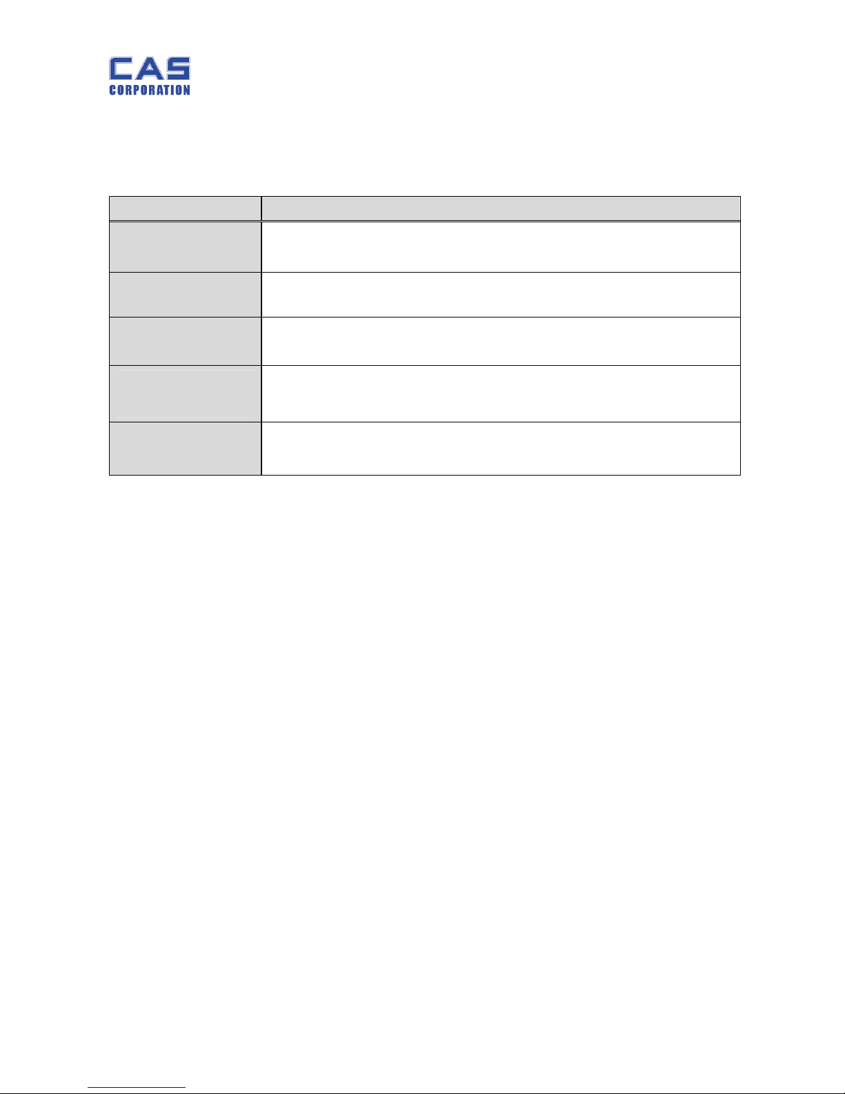
1.4. Key
Key Function
HOLD
To make the weight of item stable. This weight is average value.
UNIT
Used to convert the unit of weight
TARE
To input or cancel the tare (the weight of container).
ZERO (-O-)
[Set]
To set zero point
To do [SET] key in the SETUP mode.
POWER
To turn on or off.
Page 7
PW-II Service Manual
7
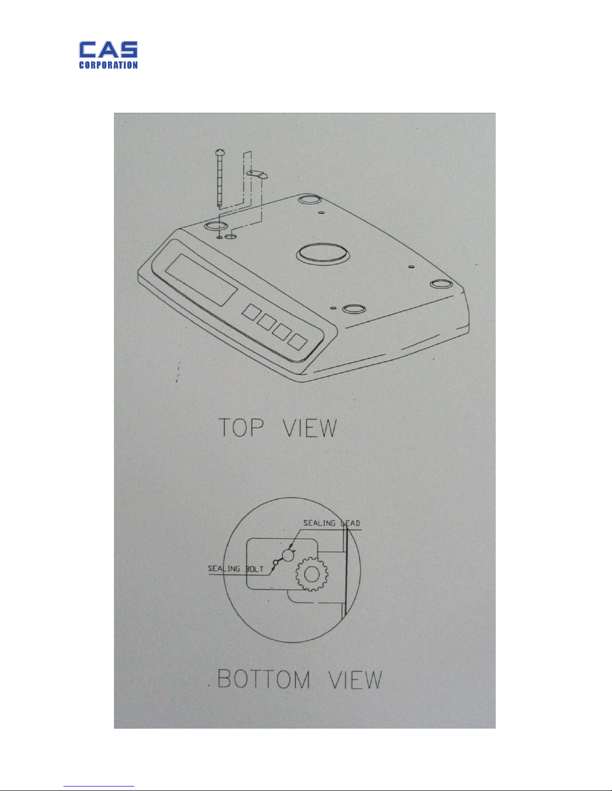
1.5. Sealing Method
Page 8
PW-II Service Manual
8
2. Calibration
2.1. General Calibration
Pressing and holding calibration switch press [POWER] key to go to calibration mode.
User can move to other mode by using [ZERO] key in the calibration mode.
User also moves to other sub-modes for each mode by using [HOLD] and [TARE] key.
Please simply follow below procedure to move to other mode.
(1) Calibration Mode: Pressing and holding “Calibration Switch ” press [POWER]
key.
It displays “C-0” after “CAL”, and it blinks the version of scale three times.
(2) Selecting menu: press [TARE] and then [HOLD].
(3) ENTER(Setting) : [ZERO] key
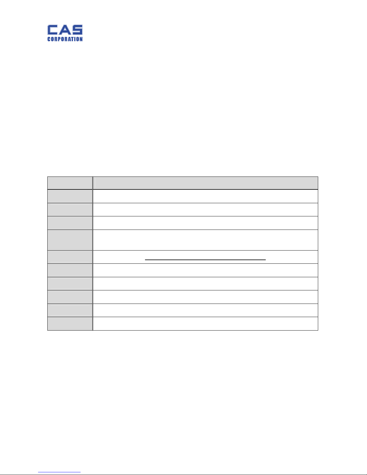
MODE Function
C – 0
To go back to simple weighing mode
C – 1
To display internal value of weight
C – 2
-
C – 3
Weight Setting Mode
(“UnLoad” → [ZERO] →“Load”→ [ZERO] after loading → “END” on display)
C – 4
Capacity displayed and Option Setting
C – 5
Net internal value of weight (zero value confirmed)
C – 6
C – 7
C – 8
C – 9
Gravity constant
Page 9
PW-II Service Manual
9
2.1.1. C4 Setting
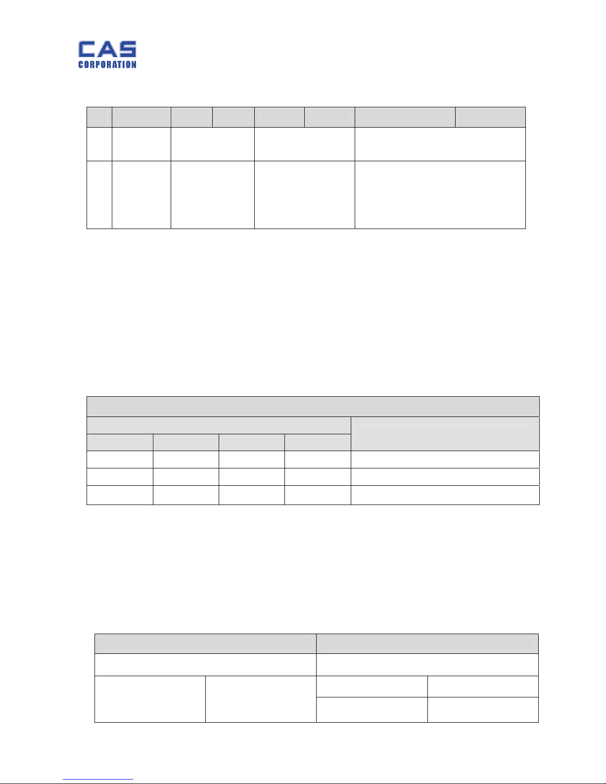
2.1.1.1. C4-1 Setting
B7 B6 B5 B4 B3 B2 B1 B0
Weight
Unit
External
Resolution
Display Unit TARE
0:kg
1:lb
00: Low
01: High
00:kg
01:lb
10:oz
11:g
00: (+)One Time (-) One Time
01: (+)Successive (-) One Time
10: (+)One Time (-) Successive
11: (+)Successive (-)Successive
User should input Hexa code to set C4.
User should input “weight unit”, “external resolution”, “display unit”, and “tare”.
For example, if you want to set “kg (0)” as the weight unit, “low (00)” as the external
resolution, or “(0)” as TARE you may input “00” as Hexa value.
User can set 2,000~2,500 for low external resolution or 4,000~5,000 for high external
resolution.
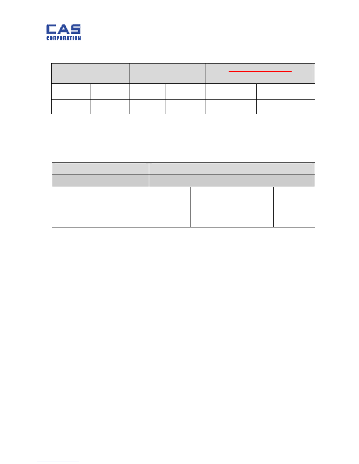
2.1.1.2. C4-2 Setting
Capacity Setting
UNIT
kg g lb
oz
C4-2 Value
2 2,000 5
80
0000 1XXX
5 5,000 10
160
0001 1XXX
10 10,000 20
400
0010 1XXX
PW-II has four different weight units, g, kg, lb, or oz as shown in shaded area. You can set
the capacity to input first 5 bits, for example, “00011” for 5 kg capacity.
Next three (3) bits represent “Interval” information . For example, if you set 5 kg interval the
Hexa value will be “0x18”.
2.1.1.3. C4-3 Setting (Function Setting)
ROM VERSION 1 (Hold) ROM Version 2 (lb)
Function Function
S-HOLD XXXX XX00
HOLD XXXX XX00
Lb XXXX XX10
Page 10
PW-II Service Manual
10
2.1.1.4. C4-4 Setting
UNIT CHANGE Comma Setting
lb ROM Version Only
Buzzer Setting
ENABLE 1XXX XXXX ENABLE XXX1 XXXX
ENABLE XXXX 0XXX
DISABLE 0XXX XXXX DISABLE XXX0 XXXX
DISABLE XXXX 1XXX
C4-4 is to set to use the unit change function and the displaying unit.
2.1.1.5. C4-5 & C4-6 Setting
2.1.2. SPAN Calibration Setting (C-3)
(1) Pressing and holding “Calibration Switch” press [POWER] key.
After “CAL” message blinks three times and shows the version of scale, it displays “C-0”
message.
(2) Press [TARE] to display “C-3”.
(3) Press [ZERO] key and then it displays “UnLOAd” message.
(4) Press [ZERO] key if you want to scroll it.
Ú To exit from SPAN Calibration mode press [TARE] key when “UnLOAd” or “LOAd” message is
displayed.
C4-5 C4-6
Op Amp Setting Zero Range Setting
HA17358 XXXX XXX1 2% 10% 15% 20%
OP2177 XXXX XXX0 XXXX XX01 XXXX XX00 XXXX XX10 XXXX XX11
Page 11

PW-II Service Manual
11
2.1.3. Gravity Constant Value Setting (C-9)
Current gravitational Acceleration value is set to 9.7994 m/s
2
.
(1) Pressing and holding “Calibration Switch” press [POWER] key.
After “CAL” message blinks three times and shows the version of scale, it displays “C-0”
message.
(2) Press [TARE] to display “C-9”.
(3) Press [ZERO] key, and then “ G-1“ message and “9.7994” will be shown. The first
digit,”9” will blink.
(4) Input a gravitational acceleration value by using [HOLD] and [TARE] key.
(5) Press [ZERO] key, and then “G-2“ message blinks.“9.7994” will be shown. The first
digit,”9” will blink.
(6) Input a gravitational acceleration value by using [HOLD] and [TARE] key.
(7) Press [ZERO] key to save the gravitational acceleration value, and “C9 END” message
will be shown shortly.
2.1.4. Displaying Real A/D Value (C-5)
(1) Under Calibration switch on press [POWER] key.
After “CAL” message blinks three times and the version of scale is displayed, “C-0” message
will be displayed.
Press [TARE] to display “C-5”.
Press [ZERO] key, and then the display will show a real A/D v alue.
Press [ZERO] key to exit from it.
Page 12

PW-II Service Manual
12
2.1.5. How to confirm SPAN calibrated A/D value (C-1)
(1) Pressing and holding Calibration Switch please press [POWER] key.
After “CAL” message blinks three times and the version of scale is displayed, “C-0” message
will be displayed.
(2) Press [TARE] to change “C-0” to “C–1”.
(3) Press [ZERO] key, and then it displays SPAN calibrated A/D value, “0”.
(4) When the weighing value of maximum capacity is not stable you may use
[TARE] key to decrease or [HOLD] key to increase the value.
For example, when you weigh maximum capacity on the platter in case of 1/20,000 it
may display “19,999” or “20,001”. You can adjust up or down to “20,000” using [HOLD] or
[TARE] key.
(5) Press [ZERO] to go to and display “C – 1” and you may scroll it at this point.
Then, if you press [ZERO] key again it automatically saves “Span Factor” on it.
2.1.6. Back to the normal weighing mode (C-0)
(1) Under the Calibration Switch ON press [POWER] key.
9 After “CAL” message blinks three times and the version of scale is
displayed, “C-0” message will be displayed.
(2) You may exit from Calibration mode by pressing [ZERO] key.
Page 13
PW-II Service Manual
13
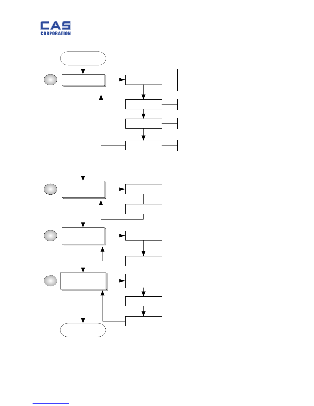
2.1.7. Calibration Block Diagram
START
C - 4
C - 4 - 1
C - 4 - 2
교정 단위
외부분해능
Display Unit
TARE O ptio
n
C - 4 - 6
Unit Change
표시 단위
C - 9
(G rav ity)
1
2
G - 1
G - 2
C - 3
(SPAN)
UnLOAd
LOAd
3
C - 1
(Tr im m in g)
4
Factored
Value
LOAd
Up/Down
END
Capacity
Interva l
C - 4 - 4
Initial Zero
Page 14
PW-II Service Manual
14
3. The Schematics and Diagram
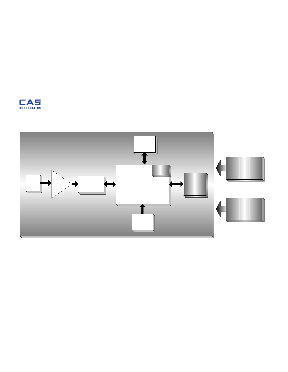
3.1. System Block Diagram
Load
Cell
A/D
Converter
(ADS1100)
CPU
( NEC 78Fseries)
KEY
EEPROM
(24C02)
AMP
&
Filter
POWER
(DC 9V/300mA)
Battery_AA SIZE
(1.5V x 6)
LCD
Driver
DISPLAY
(LCD)
Page 15
PW-II Service Manual
15
3.2. Circuit Diagram
3.2.1. Main
S1 ZERO
C
Q2
KTN2222AS
Q4
KTN2222AS
VDD
R6
100K
C13
0.1uF
Vbat
0
PW-2 MAIN CIRCUIT DIAGRAM
A3
11Saturday, August 26, 2006
Title
Size Document Number Rev
Date: Sheet
of
S3 HOLD
C19
0.1u
Low Battery Check
R15
100k
R3
10K
C12
0.1u
R13
10k
CN62
J1
1
2
3
S4
ON/OFF
CAL S/W
E
VDD
L6
471u
CY1
Q3
KTA1504SY
Q1
2N2222AS
R14
10k
V+
Vin
POWER_CHK
1
+
C3
330u/25v
C10
30p
B
S2 TARE
U5
1
2
3
4
5
6
VIN+
GND
SCL
SDA
VDD
VIN-
R9
0.5%
10k
BUZZER
12345
678910
12345
678910
+
C1
1u/50v
R4
10k
VDD
R7
100K
C5
0.1uF
D1
KDS184
2 1
3
KTA1504
U3
24C02
1
2
3
45
6
7
8
A0
A1
A2
VSSSDA
SCL
WP
VDD
VDD
LCD1
SW-II LCD
1 23467895
11121314151617181920211022
C0C1C2
C3
STABLE/L/ O/K
1F/1G/1E/ 1D
1A/1B/1C/
/ /1P/1Z
S2/S3/ S4/HI
2A/2B/2C/
/ /2P/2Z
3F/3G/3E/ 3D
3A/3B/3C/
/ /3P/3Z
4F/4G/4E/ 4D
4A/4B/4C/
/ /4P/4Z
5F/5G/5E/ 5D
5A/5B/5C/
OZ/LB/ K/ G
2F/2G/2E/ 2D
PCS
VDD
AUTO POWER
2E
C11
30p
R22
100
U2
XC6204C502MR
1
2
3
5
VIN
VSS
CE
VOUT
VDD
FROM A/D
VDD
KTN2222AS
C
+
C4
100u/16v
R10 10k
R18
2.2k
JP1
1 2
B
R12
10k
6100-PW2-0000-0
KTN2222AS
R11 10k
CAL S/W
C6
0.1uF
POWER_CHK
AUTO POWER
B
KDS184
R5
100
C3
E
U2 uPD789324
1
2
3
4
5
6
7
8
9
10
111213
1415161718192021222324252627282930
35
383940
41
42
43
44
45
46
47
48
49
50
51
52
343132
33
reset
P60/TO40
P43/KR03
P42/KR02
P41/KR01
P40/KR00
P03
P02
P01
P00
INT/P 61
P11
P10
COM0
COM1
COM2
COM3S0S1S2S3S4S5S6S7S8S9
S10
S11
S12
S17
P82/S20
P81/S21
P80/S22
S23
VLC0
P22/SI10
P21/SO10
P20/SCK10
ICO(VPP)
XT1
XT2
Vss
VDD
X2
X1
S16
S13
S14
S15
VDD
L5
471u
VDD
VIN+
R8
12K
Page 16
PW-II Service Manual
16
3.2.2. A/D
VCC
VIN+
C8
1 uF
C23
1uF(105)
R20
600k
L9
1 2
MMZ1608Y102C
C22
0.1uF
+VIN
VIN-
L8
1 2
SIG-
VCC
6100-PW2-0000-0
C14
미사용
C17
0.1uF
0
PW-II A/D CIRCUIT DIAGRAM
11Saturday , Augus t 26, 2006
Titl e
Size Document Number Rev
Date: Sheet
of
R21
150K
VDD
(C105)
+
C2
330u
A4
MMZ1608Y102C
L2
471u
MMZ1608Y102C
R17
100k
VIN+
L1
471u
L7
1 2
J2
L/C CON 1
1
2
3
4567
8
9
10
L10
1 2
SIG+
C18
0.1uF
C20
1 uF
MMZ1608Y102C
VCC
CHIP BEAD
C9
0.1uF
R16
50k
VDD
(C105)
SIG+
SIG-
+
-
U4B
HA17358
5
6
7
84
C15
0.1uF
R19
150K
To L/ C
L4
471u
VIN-
(C105)
+
-
U4A
HA17358
3
2
1
84
C7
1 uF
L3
471u
C16
0.1uF
Page 17
PW-II Service Manual
17
4. Exploded View
Page 18
PW-II Service Manual
18
5. Part Location
5.1. Main PCB (Front)
Page 19
PW-II Service Manual
19
5.2. Main PCB (Rear)
Page 20
PW-II Service Manual
20
5.3. BATTERY PCB
Page 21
PW-II Service Manual
21
5.4. KEY PCB
Page 22
PW-II Service Manual
22
6. Part List
6.1. Circuit Part
6.1.1. Main PCB Ass’y
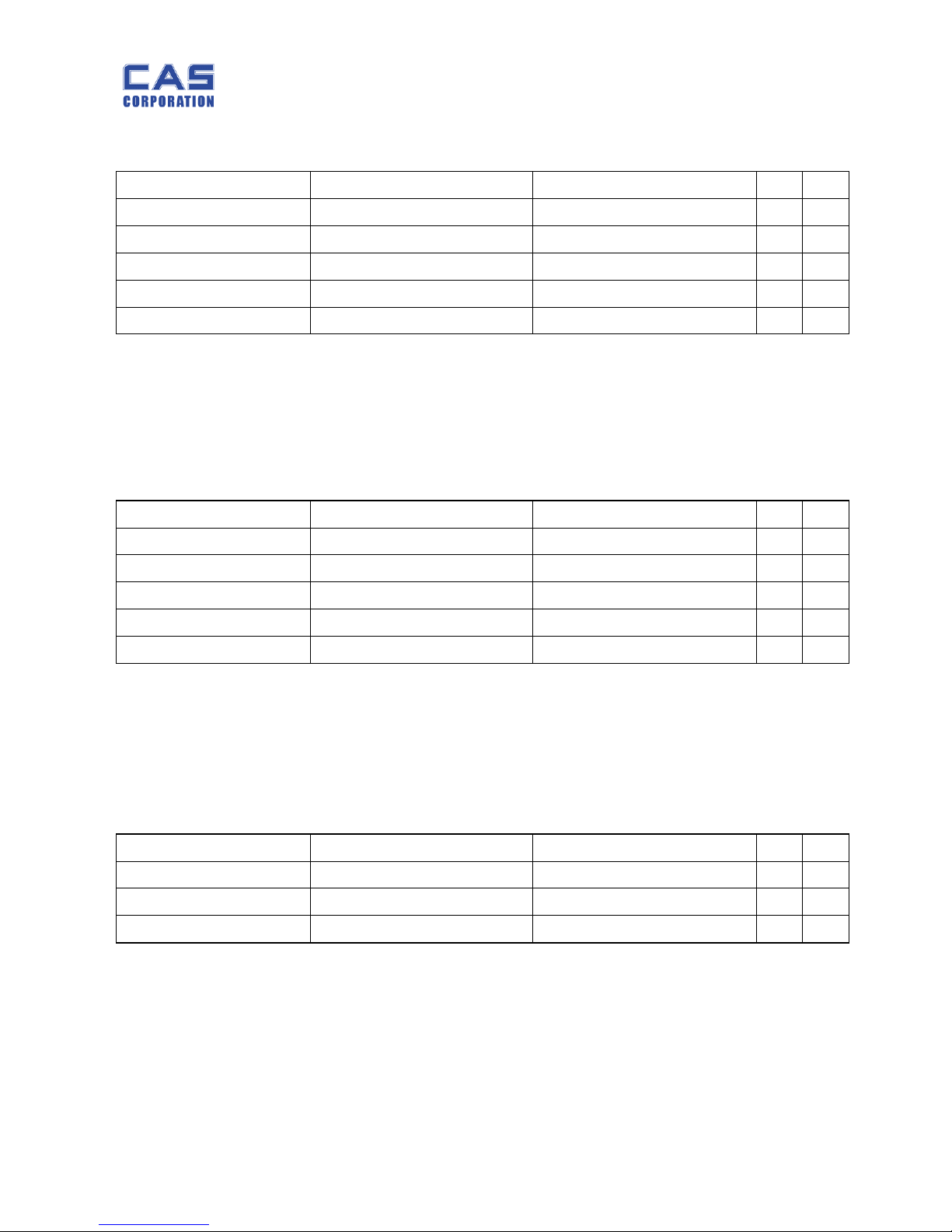
Parts Code Parts Name 규 격 Unit Q'ty
2631-A00-0001-0 CUSHION-VFD 30*20*2T EA 4
6100-PPW-0000-0 PCB-MAIN 6100-PPW-0000-0(PW-II) EA 1
7212-D00-8230-A LCD PW-II LCD EA 1
6200-IPU-0512-0 IC(CPU) SW-2(MASKING) EA 1
6205-IS0-2402-0 IC(EEP ROM) AT24C02-SMD(2K) EA 1
6214-IS0-1110-0 IC(A/D CONVERTER) ADS1100 EA 1
6220-IS0-C502-0 IC(REGULATOR) XC6204C502MR(5.0V) EA 1
6240-IS0-0358-A IC(OP AMP) HA17358ARP EA 1
6281-I00-1504-0 TRANSISTOR CHIP KTA1504 SY EA 1
6281-I00-2222-0 TRANSISTOR CHIP 2N2222AS EA 4
6294-ICP-0184-0 DIODE-CHIP KDS184 EA 1
6527-IJ0-1000-0 RESISTOR-CHIP 1/10W FTR 0805 000 JR(0Ω) EA 1
6527-IJ0-1000-0 RESISTOR-CHIP 1/10W FTR 0805 101 JR(100Ω) EA 1
6527-ID3-0020-0 RESISTOR-CHIP 1/10W RR1220P-202D(2 ㏀) EA 1
6527-IJ3-0022-0 RESISTOR-CHIP 1/10W FTR 0805 222 JR(2.2K) EA 1
6527-IJ3-0100-0 RESISTOR-CHIP 1/10W FTR 0805 103 JR(10K) EA 7
6527-ID3-0300-0 RESISTOR-CHIP 1/10W RR1220P-303D(30 ㏀) EA 2
6527-ID3-0499-0 RESISTOR-CHIP 1/10W RR1220P-4992D(49.9K) EA 1
6527-ID3-1000-0 RESISTOR-CHIP 1/10W RR1220P-104D(100K) EA 8
6527-ID3-2700-0 RESISTOR-CHIP 1/10W RR1220R-274D(270K) EA 2
6527-ID3-3000-0 RESISTOR-CHIP 1/10W RR1220R-304D(300 ㏀) EA 1
6670-T00-0102-0 INDUCTANCE HB-1M2012-102JT(TP2,LP EA 6
6704-C16-0100-0 CONDENSER-ELECTRIC 100uF/16V EA 1
6704-C25-0330-0 CONDENSER-ELECTRIC 330uF/25V EA 2
6704-C50-0001-0 CONDENSER-ELECTRIC 1uF/50V EA 1
6712-CHP-0104-0 CONDENSER-CHIP CL21F 104KBNC EA 11
6712-CHP-0105-0 CONDENSER-CHIP 105(1uF-0805 TYPE) EA 4
6712-CHP-0200-0 CONDENSER-CHIP CL21C 200JBNC(20PF) EA 1
6712-CHP-0300-0 CONDENSER-CHIP CL21F 300JBNC EA 2
6800-F00-0102-A FERRITE BEADS SMD MMZ 1608 Y102C EA 4
7002-Z00-0000-0 PIEZO BUZZER APR,ADR(CHINA) EA 1
Page 23
PW-II Service Manual
23
6.1.2. Battery PCB Ass’y
6.1.3. Key PCB Ass’y
Parts Code Parts Name 규 격 Unit Q'ty
7010-ZM0-0400-D RESONATOR 4MHz-SW1S/1C EA 1
7809-CAL-0003-0 CONNECTOR(WAFER) LAL0640-03 (LAW250-03) EA 1
7809-CAL-0005-0 CONNECTOR(WAFER) LAL0640-05 (LAW250-05) EA 1
7813-C00-0025-0 SOCKET CONNECTOR HD2*25(TP-R)MALE EA 0.2
7821-CJM-0002-0 JUMPER 2PIN SET 1
Parts Code Parts Name 규 격 Unit Q'ty
6140-PPW-0000-0 PCB-BATTERY 6140-PPW-0000-0(PW-II) EA 1
1060-A00-0010-0 BATTERY CONTACT 12*10*7.5*0.4t(PORTION EA 12
1590-A00-0005-0 COIL SPRING ø0.5 *ø8.2* 5.4(PW) EA 6
7809-CAL-0003-0 CONNECTOR(WAFER) LAL0640-03 (LAW250-03) EA 2
7600-STA-1902-0 TACT S/W 11902(DJTA-1102) EA 1
Parts Code Parts Name 규 격 Unit Q'ty
6130-PPW-0000-0 PCB-KEY 6130-PPW-0000-0(PW-II) EA 1
7600-STA-1212-0 TACT S/W 12*12(SKHK)DJTA-1103E EA 4
7850-W00-1212-B FLAT CABLE CONNECTOR 5P*5P*120MM(PW-II) EA 1
Page 24
PW-II Service Manual
24
6.2. Mechanism Part
6.2.1. Body Ass’y
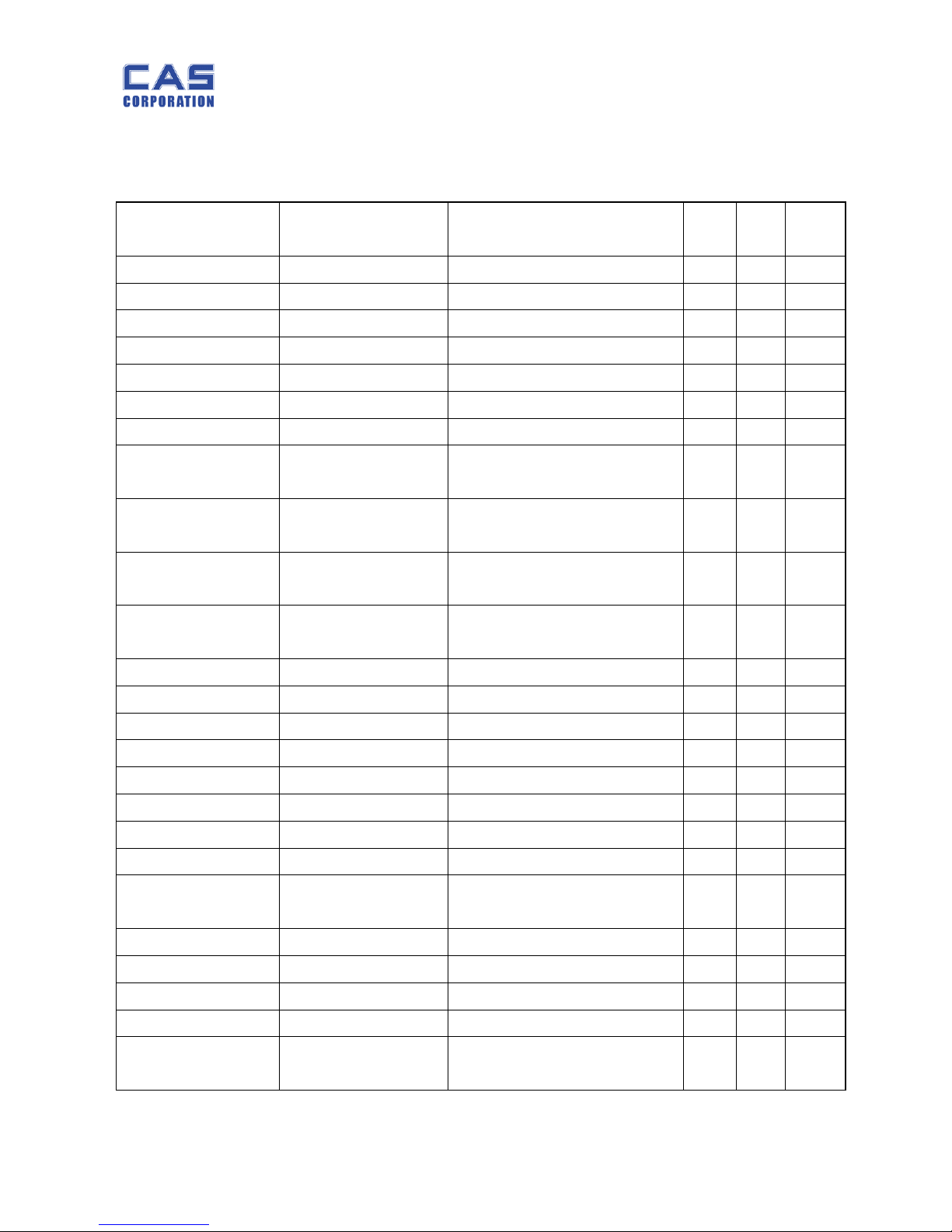
Parts Code Parts Name 규 격 Unit Q'ty
E.V
No
1000-A00-0029-A TRAY PW-I(POLISHING) EA 1 10
1000-A00-0062-0 BATTERY COVER 110*60.6*1T(PW) EA 1 5
1000-A00-0100-0 UPPER CASE PW-1(POLISHING) EA 1 2
1050-A00-0007-0 PLATFORM AL200*126*2T(PW-2,3K) EA 1 9
1100-A00-0032-B BRACKET-L/C PW EA 1 7
1100-A00-0250-G BODY PW-1 EA 1 1
1215-A00-0120-0 PCB SPACER ø8*10.8(CI-2001AS,PW) EA 4 14
1261-A00-0003-0
BOLT-BATTERY
COVER
M4*0.7*8.5(SUS)PORTION EA 1 20
1502-A00-0406-0
SCREWMACHINE(PH)
M4*6 EA 12 17
1502-MHO-0450-0 SCREW-
MACHINE(PH)
M4*50 MHO(PORTION) EA 1 13
1502-MSU-0408-0
SCREWMACHINE(PH)
M4*8-SUS EA 3 18
1530-MSU-0510-0 BOLT-WRENCH M5*1.0*10-SUS EA 6 15,16
1540-A00-0300-0 NUT(HEX) M3*0.5 EA 4 19
1561-MSU-0300-0 E-RING ø3*ø7*0.6-SUS EA 1 21
1810-PW0-0033-0 SPEC PLATE PW(영공)STICKER 용 EA 1 8
2001-A00-0021-0 D/C JACK COVER 73.9*50.2*24(PW) EA 1 6
2003-A00-0001-0 FOOT ø20*17,M5*16(MW) EA 4 12
2200-PW1-0233-0 KEY BOARD PAD PW-2 (2kg) ENGLISH EA 1 4
2600-A00-0015-0 TRAY RUBBER ø14*18.7(PORTION) EA 4 11
2600-A00-0049-0
SUPPORT BRACKET
HOLDER
ø13*5.5(PW) EA 1
2600-A00-0059-0 S/W HOLE COVER NBR, 24*20*7(PW) EA 1 22
7642-S00-0060-0 METAL CLAMP 6N EA 2 25
7840-W00-0214-0 CONNECTOR WIRE 3P*230mm-303(EP,SW) EA 1 26
7840-W00-0308-A CONNECTOR WIRE 3P*3P*80MM(PW-II) EA 1
9300-A00-0009-0
BATTERY COVER
CUSHION
75*50*1T(P.E) EA 1
Page 25
PW-II Service Manual
25
6.2.2. C/T Box Ass’y
6.2.3. Loadcell Ass’y
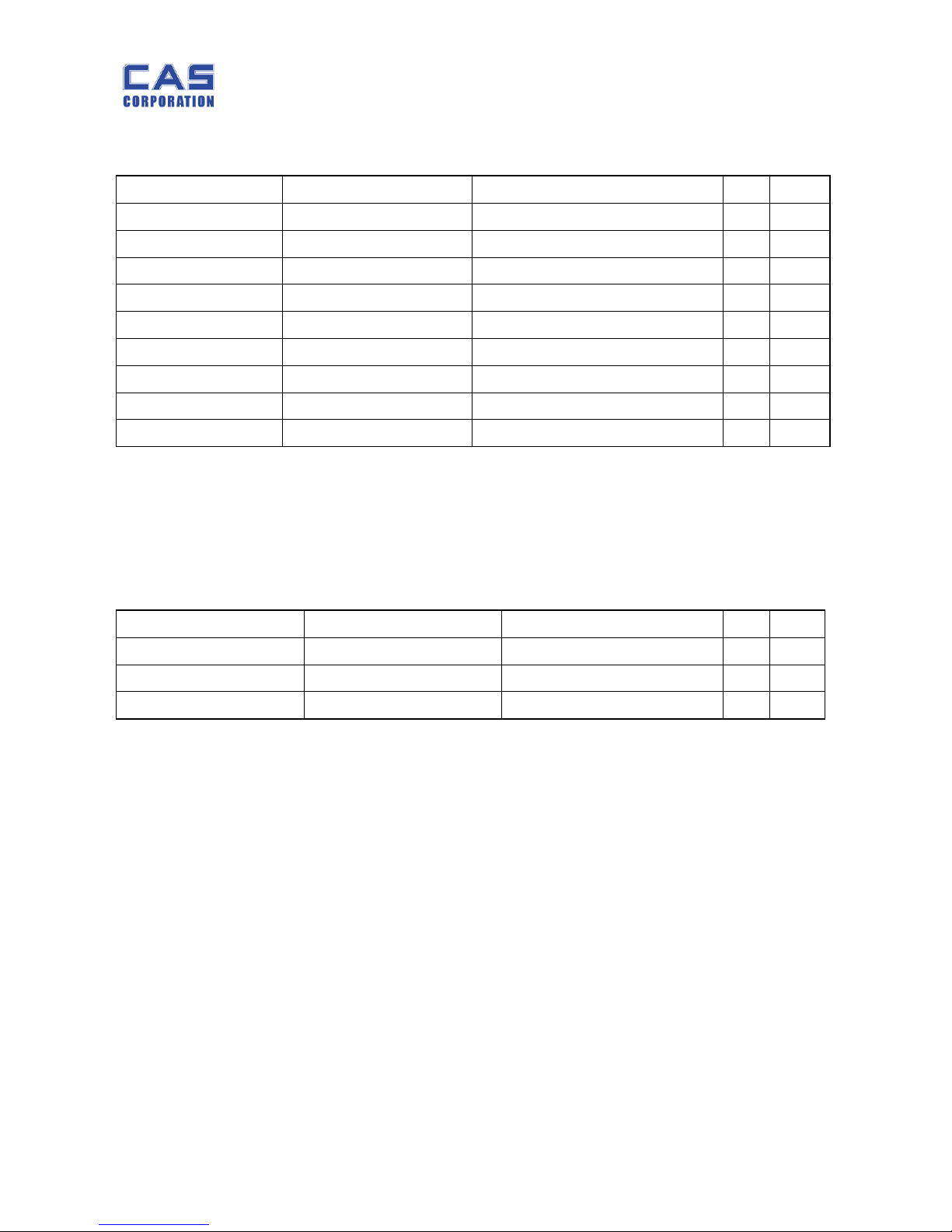
Parts Code Parts Name 규 격 Unit Q'ty
7510-P09-0240-D ADAPTOR 240V 9V/300mA(CE) EA 1
9002-PW1-0033-0 MANUAL PW-II(영문) EA 1
9100-PW1-0133-0 C/T BOX CAS PORTION(영문) EA 1
9100-PW0-0630-0 C/T BOX 590*315*360 PORTION 6E EA 0.2
9203-AS0-0001-0 STYROFOAM BOX 301*109*80(PORTION) SET 1
9301-A00-0003-0 POLY BAG 170*250*0.05T(MANUAL) EA 1
9301-A00-0004-0 POLY BAG 190*260*0.03T(DISPLAY) EA 1
9302-A00-0005-B POLY BAG 270*350*0.04T(MW,PW) EA 1
9400-A00-0046-0 SILICAGEL 10g EA 2
Parts Code Parts Name 규 격 Unit Q'ty
8ZSW0KK00200(2kg) LOADCELL SW-02L(CHINA) SET 1
8ZSW0KK00500(5kg) LOADCELL SW-05L(CHINA) SET 1
8ZSW0KK01000(10kg) LOADCELL SW-10L(CHINA) SET 1
Page 26

PW-II Service Manual
26
7. Error Messages & Solution
7.1. Beep: Re-zero
The range of “Re-zero” is within ± 2% of full capacity. However, when the scale is out of th is
range it automatically beeps to notify to user that “Re-zero” function does not work in this
range.
7.2. Err: Initial Zero
You may set 2% or 10% of full capacity as Initial Zero.
When you place an item more than the initial zero setting value (2% or 10% of full capacity)
and turn on the scale it display “Err” message and does not work.
However, you can make the scale work if you make the item’s weight be within the initial
zero setting range (2% or 10% of full capacity) by decreasing the value of weight.
7.3. Init: Failure of Analog Module
“Init” message shows up when there is some problem on analog module.
Please turn off the scale and turn on. If you still have “Init” message on display please
contact CAS A/S service.
7.4. UNSTA: A/D Value Unstable
The scale displays “UNSTA” when it is in unstable status or in low-power supply.
If the scale is not properly balanced, please adjust the 4 legs at the bottom of the scale (turn
legs clockwise or counterclockwise) so as to center the bubble of the leveling gaug e inside the
indicated circle. And if the scale is in low power supply please replace the battery or plug in
adapter.
However, if you still have “UNSTA” problem please contact CAS A/S service.
 Loading...