

Page 1

PR-T Service Manual
1 8/31/2015
PR-T SERVICE MANUAL
Page 2

PR-T Service Manual
2 8/31/2015
< Table of Contents >
1. Introduction ......................................................................................................................... 3
1.1. Preface ............................................................................................... 3
1.2. Precaution .......................................................................................... 3
1.3. Specifications ..................................................................................... 4
1.4. Dimension ........................................................................................... 5
1.5. Key & Symbols .................................................................................... 6
1.6. SealingMethod .................................................................................... 7
2. Calibration ............................................................................................................................. 8
2.1. General Calibration ............................................................................. 8
2.1.1. C4 Setting C4-1 Setting ............................................................................... 9
2.1.2. SPAN Calibration Setting (C-3) ..... 오류! 책갈피가 정의되어 있지 않습니다.
2.1.3. Gravity Constant Value Setting (C-9) ......................................................12
2.1.4. Calibration factor Setting (C-10) ...............................................................12
2.1.5. Displaying Real A/D Value (C-5) .. 오류! 책갈피가 정의되어 있지 않습니다.
2.1.6. Input Function Key Code (C-6) ..... 오류! 책갈피가 정의되어 있지 않습니다.
2.1.7. Percent Calibration (C-7) ................ 오류! 책갈피가 정의되어 있지 않습니다.
2.1.8. Battery Calibration (C-8) ................ 오류! 책갈피가 정의되어 있지 않습니다.
3. Error Messages & Solution ............................................................................................ 15
4. The Schematics and Diagram ...................................................................................... 16
4.1. System Block Diagram ...................................................................... 16
4.2. Circuit Diagram ................................................................................. 17
4.2.1. Main ................................ ................................ ................................ .....................17
4.2.2. Power Part ........................................................................................................18
4.2.3. Key Part .............................................................................................................19
4.2.4. Display Part ......................................................................................................20
5. Exploded View ................................................................................................................... 21
5.1. BODY ................................................................................................ 21
5.2. Load Cell drawing ............................................................................. 22
6. Part ........................................................................................................................................ 23
6.1. Part Location .................................................................................... 23
6.1.1. Main PCB (Bottom) .........................................................................................24
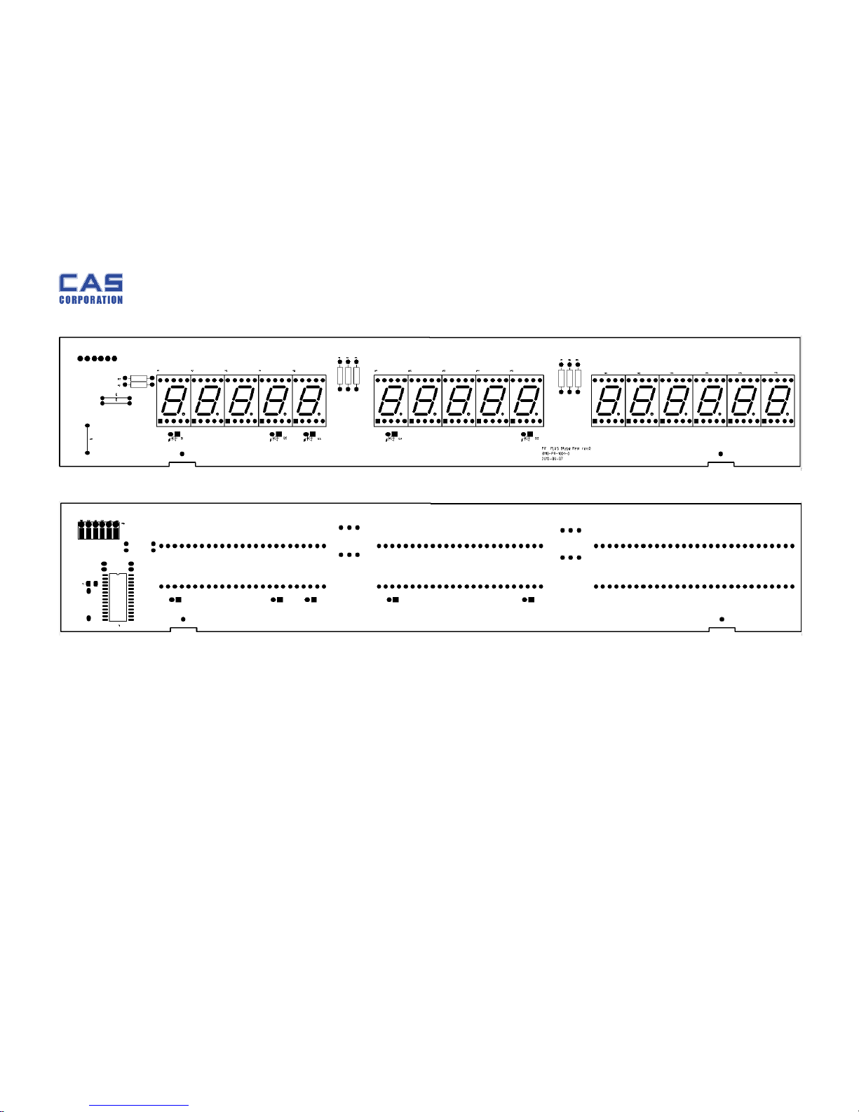
6.1.2. Front Display PCB (Top) ...............................................................................25
6.1.3. Front Display PCB (Bottom) ........................................................................26
6.1.4. Rear Display PCB (Top) ................................................................................27
6.1.5. Rear Display PCB (Bottom) .........................................................................27
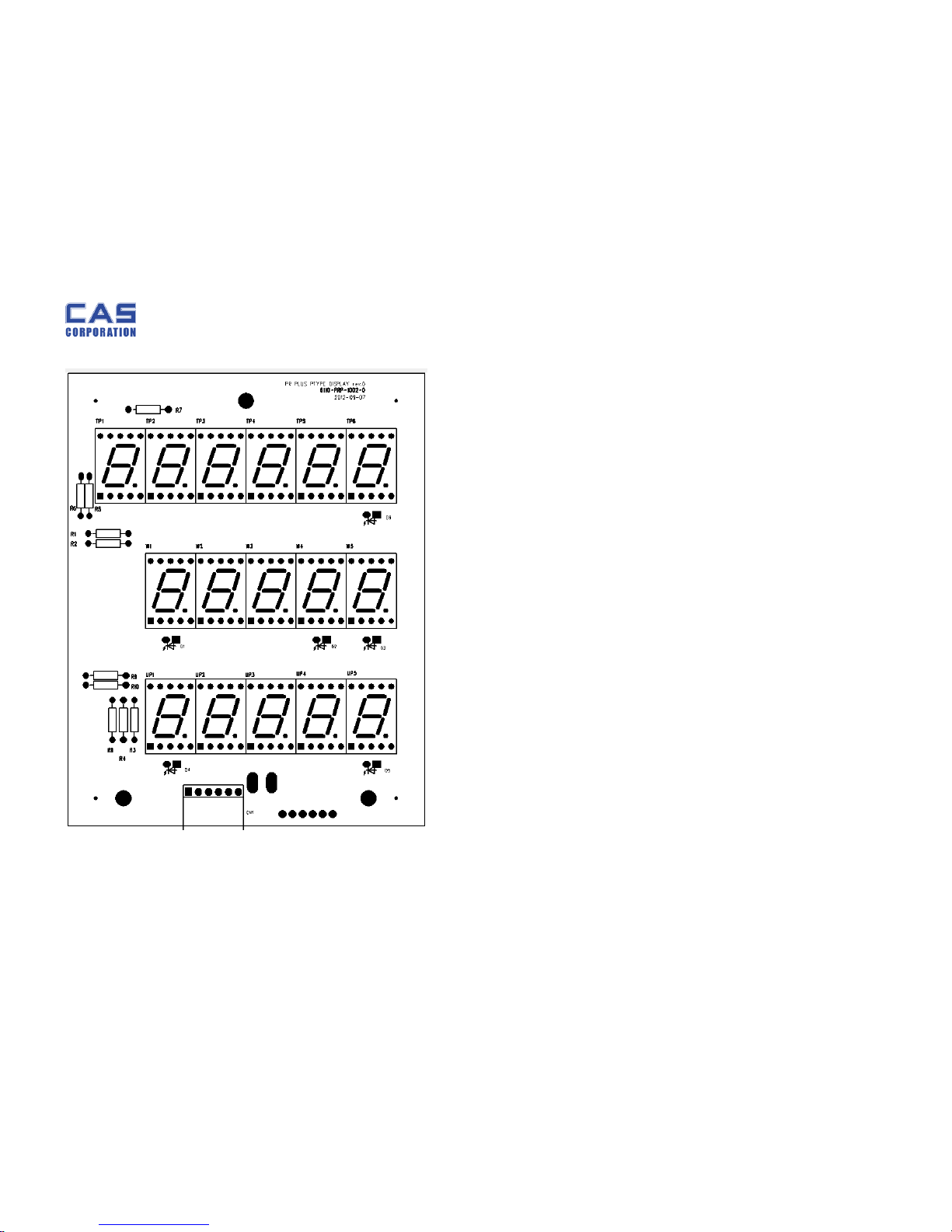
6.1.6. Pole Display PCB (Top) .................................................................................28
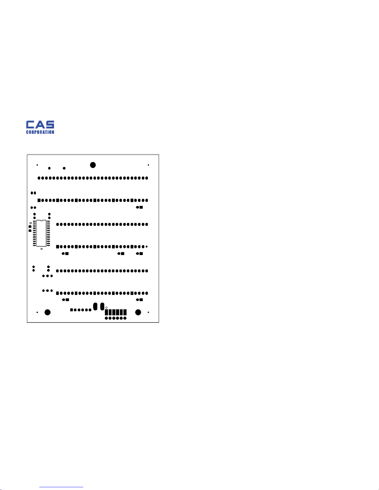
6.1.7. Pole Display PCB (Bottom) ..........................................................................29
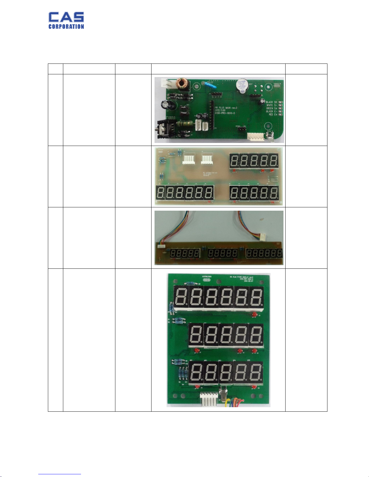
6.2. Part Order List .................................................................................. 30
Page 3

PR-T Service Manual
3 8/31/2015
1. Introduction
1.1. Preface
Thank you for purchasing of our CAS scale.
This scale has been designed with CAS reliability, under rigid quality control
and with outstanding performance.
WE hope that your departments enjoy with high quality of CAS product.
This manual will help you with proper operations and care of the PR series.
Please keep it handy for the future references.
1.2. Precaution
Make sure that you plug your scale into the proper power outlet.
Place the scale on a flat and stable surface.
Plug into a power outlet 30 minutes before operations.
Keep the scale away from strong EMI noises may cause incorrect weight readings.
This scale must be installed in a dry and liquid free environment.
Do not subject the scale to sudden temperature changes.
Do not subject the platter to sudden shocks.
If the scale is not properly level, please adjust the 4 legs at the bottom of the scale
(turn legs clockwise or counterclockwise) so as to center the bubble of the leveling
gauge inside the indicated circle.
Page 4
PR-T Service Manual
4 8/31/2015
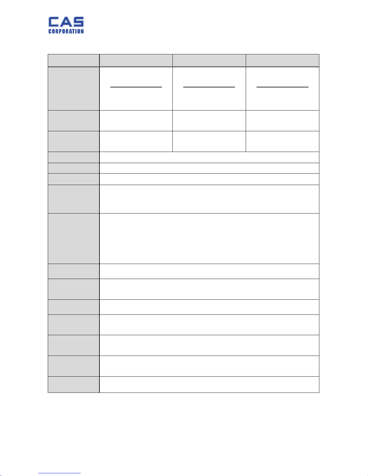
1.3. Specifications
PR-T – 6 PR-T – 15 PR-T – 32
Capacity
Single Interval
6 kg / 0.001 kg
Single Interval
15 kg / 0.002 kg
Single Interval
32 kg / 0.005 kg
Internal
Resolution
1 / 60,000 1 / 60,000 1 / 60,000
External
Resolution
1 / 6,000 1 / 7,500 1 / 6,400
Display
7 / 7 / 7(Total price / Weight / Unit price)
Symbols Power, Battery, Zero, Stable, Tare, Discount, Caps, Sum
Interface RS232
Keys
Number(0~9), Direct PLU(01~30),
ZERO, TARE, Feed, Discount, Menu, PLU call, Total,
Add, Void, Clear, Multiply, Print
Function
Direct PLU(30)
Ticket Printing scale
Low Battery Indication function
Auto Power Off
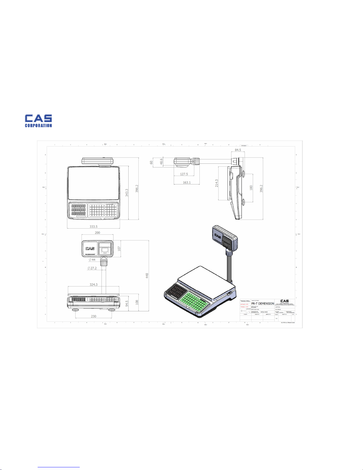
Product Size
333.5(W) X 396.2(D) X 448(H)
Product
Weight
3.8 kg
Platter Size 324(W) X 214(D)
Operating
Temperature
- 10 C ~ +40 C
Power
Source
AC( 220V-240V, 50Hz/60Hz), Pb Battery(12V 2.6AH)
Power
Consumption
APPROX 4.0W
Options Recharge Battery
Page 5
PR-T Service Manual
5 8/31/2015
1.4. Dimension
Page 6
PR-T Service Manual
6 8/31/2015
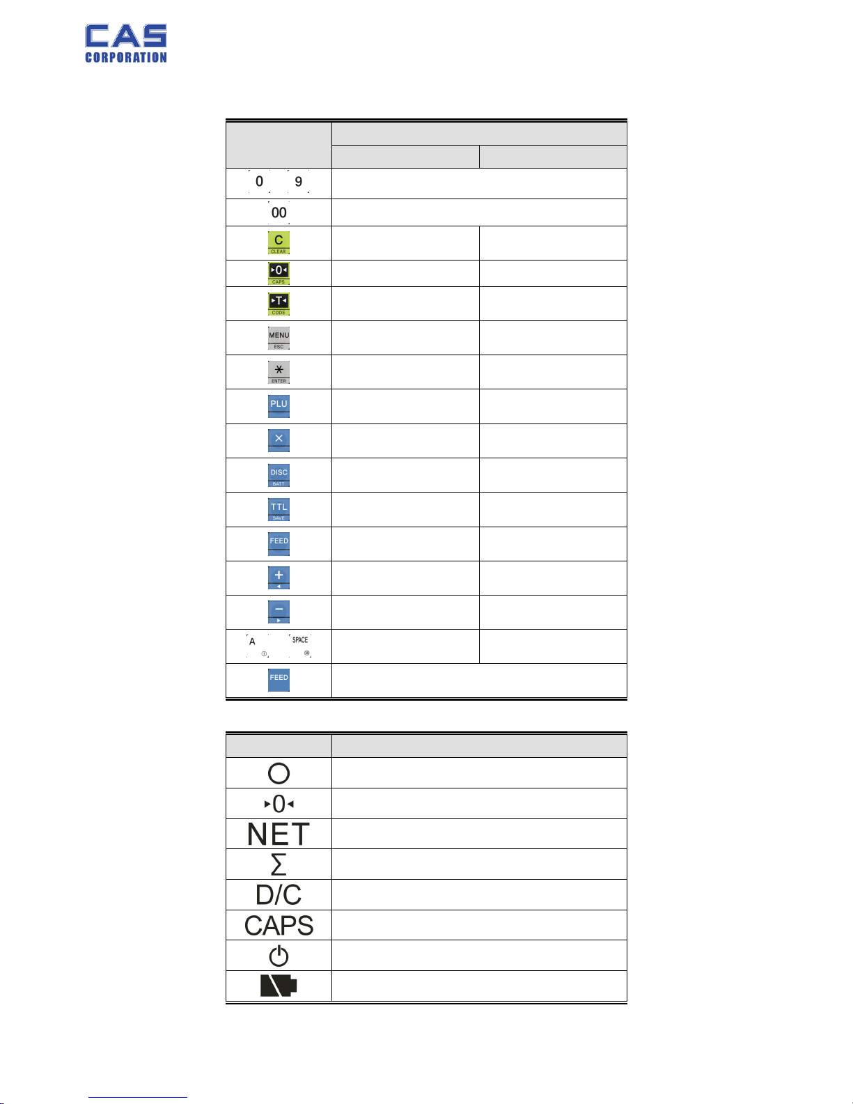
1.5. Key & Symbols
■ Function keys
KEYS
FUNCTIONS
SALES MODE PROGRAM MODE
~
To input all numerical data
To input double zero
To clear all of numbers
input on the display
To set zero
To set or clear tare value
To go to program mode
To call up a PLU with
numeric key
To input non-weighed
item
SHIFT : To select
alternate key functions
To show subtotal / total /
payment sum
~
Direct PLU keys
Alphabet Key(A~Z key)
To change key map
Table 2 : Symbols on Display
SYMBOLS DESCRIPTION
Stable Indicator
To adjust the weight to zero.
Tare on
In the subtotal mode
Discount price
To adjust the weight to zero.
AC Power On
Low battery warning when it is below residual 20 %
Page 7
PR-T Service Manual
7 8/31/2015
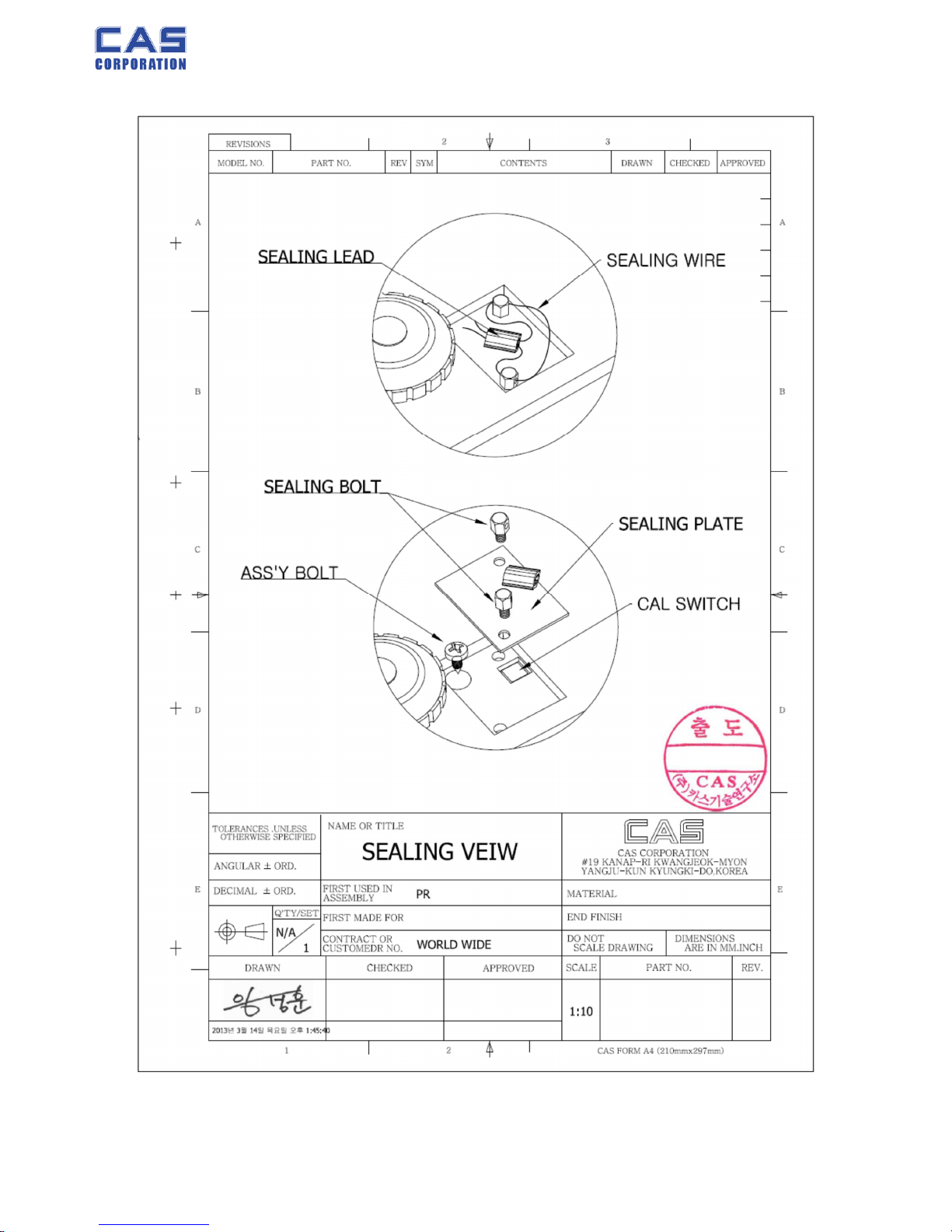
1.6. SealingMethod
Page 8
PR-T Service Manual
8 8/31/2015
2. Calibration
2.1. General Calibration
Pressing and holding calibration switch press [POWER] key to go to calibration mode.
User can move to other mode by using [ZERO] key in the calibration mode.
User also moves to other sub-modes for each mode by using [TARE] key.
Please simply follow below procedure to move to other mode.
(1) Calibration Mode: Pressing and holding “Calibration Switch” press [POWER] key.
(2) It displays “CAL-0” after “CAL”, and it blinks the version of scale three times.
(3) Selecting menu: press [TARE].
(4) ENTER(Setting) : [TARE] key
MODE Function
CAL 1
Display normalized AD
CAL 2
Display Keypad infomation-
CAL 3
Weight Setting Mode
“UnLoad” → [TARE] →
“MIDD” → [TARE] after loading for mid-capacity weight →
“FULL” → [TARE] after loading for Full weight →
“MIDD” → [TARE] after loading for mid-capacity weight → “END”
CAL 4
Option Setting ( Table 1 참조 )
CAL 5
Display filtered Raw ADx
CAL 6
Function setting on each Key ( Table 2 참조 )
CAL 7
% Calibration
CAL 8
Battery calibration
CAL 9
Gravity constant
CAL 10
Set calibration factor
“Unit” [TARE] select 0, 1 (0:kg, 1: lb) [TARE]
“CAPA” [TARE] select capacity [TARE]
“MCAPA” [TARE] select mid-capacity [TARE]
“W-dP” [TARE] Select Decimal Point [TARE]
“ 1 d ” [TARE] Select division [TARE]
“Dual” [TARE] Enable dual interval (0:disable, 1:enable) TARE
CAL 11
Set nation(00 : OIML , 01 : NTEP , 02: KOREA)
Page 9
PR-T Service Manual
9 8/31/2015
< Modes >
2.1.1. SPAN Calibration Setting (C-3)
(1) Pressing and holding “Calibration Switch” press [POWER] key.
After “CAL” message blinks three times and shows the version of scale, it displays “CAL 1”
message.
(2) Press [ZERO] to display “CAL-3”.
(3) Press [TARE] key and then it displays “zero ” message.
(4) Press [TARE] key and then it displays “midup” message
(5) Load middle weight (ex:1/3 full capacity) on the platform
(6) Press [TARE] key and then it displays “span ” message
(7) Load full weight on the platform
(8) Press [TARE] key and then it displays “middn” message
(9) Load middle weight (ex:1/3 full capacity) on the platform
(10) Press [TARE] key and then it display “CAL 3” message
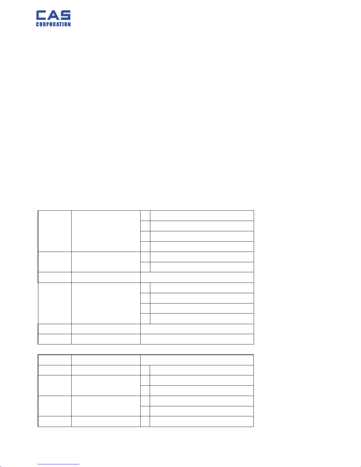
2.1.2. C4 Setting
1) C4-1 Setting
BIT 6~7 Initial Zero range
3 5%
2 10%
1 3%
0 2%
BIT5 Tare Type
0 Proper tare
1 Full Tare
BIT4
BIT 2~3
Successive tare
3 (+), (-) Direction successive Tare
2 (-) Direction successive Tare
1 (+) Direction successive Tare
0 One Time tare
BIT1
BIT0
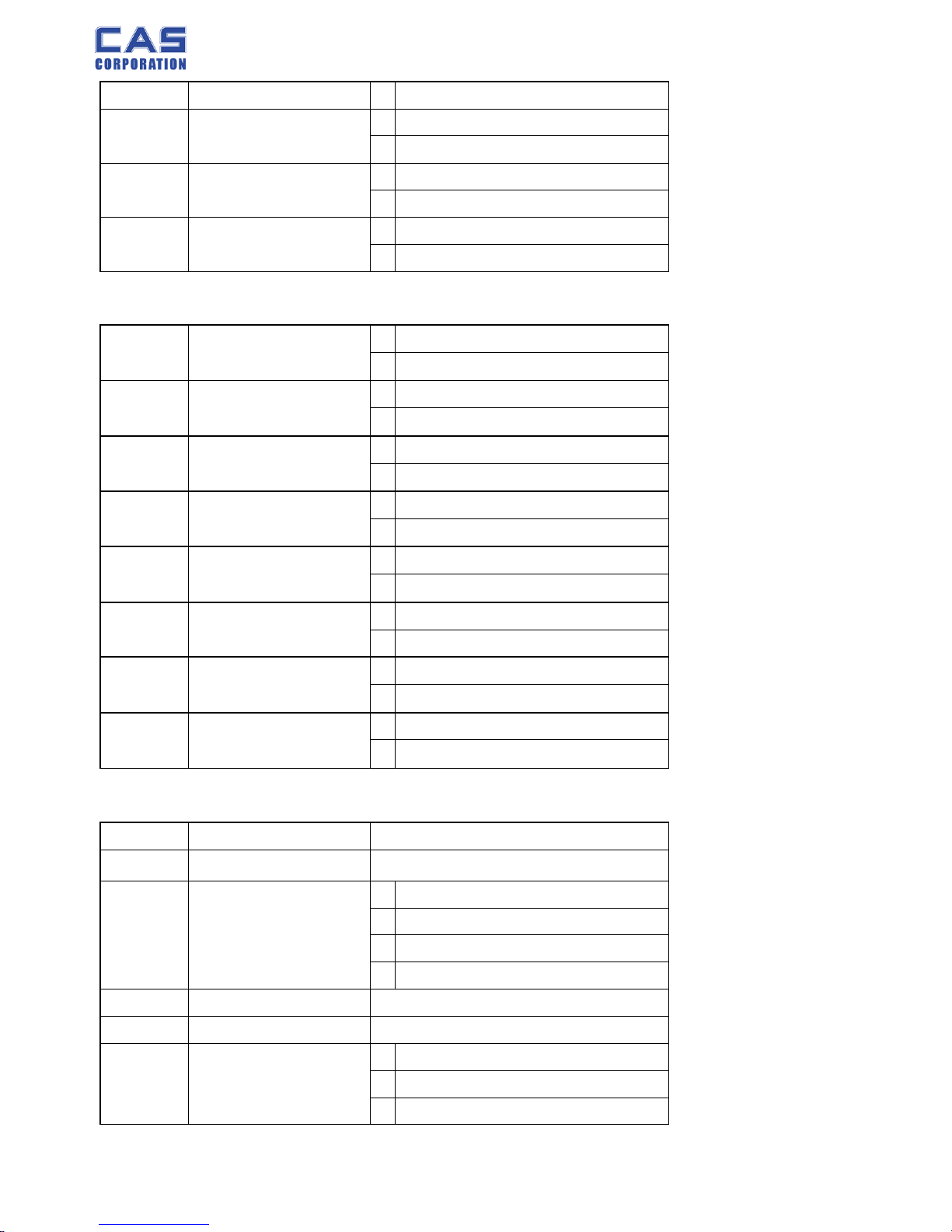
2) C4-2 Setting
BIT7
BIT6 Use PLU Tare 1 Use
BIT5 Use PLU Name
0 Don't use
1 Use
BIT4 Use Daily Total
0 Don't use
1 Use
BIT3 Clear Price 0 Don't clear
Page 10
PR-T Service Manual
10 8/31/2015
1 Clear
BIT2 Clear Tare
0 Don't clear
1 Clear
BIT1 Use Euro
0 Don't use
1 Use
BIT0 Power On Euro
0 No
1 Yes
3) C4-3 Setting
BIT7 Dot Type
0 "." dot
1 "," comma
BIT6 Use Preset tare
0 Don't use
1 Use
BIT5 Use Back light
0 Don't use
1 Use
BIT4 Use Head message
0 Don't use
1 Use
BIT3 Use gram
0 Don't clear
1 Clear
BIT2 Use oz
0 Don't clear
1 Clear
BIT1 Use lb
0 Don't use
1 Use
BIT0 Use Kg
0 No
1 Yes
4) C4-4 Setting
BIT7 X
BIT6 X
BIT 4~5 Price round off
3 00, 25, 50, 75
2 00, 10, 20
1 0, 5
0 normal
BIT3 X
BIT2 X
BIT 0~1 Unit / Price
3 1000/1
2 100/1
1 10/1
Page 11
PR-T Service Manual
11 8/31/2015
0 1/1
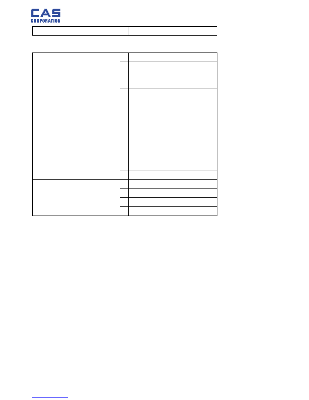
5) C4-5 Setting
BIT7 Use Standby time
0 Don't use
1 Use
BIT6 Price decimal point
7 Special case
6 O.OOOOOO
5 O.OOOOO
4 O.OOOO
3 O.OOO
2 O.OO
1 O.O
0 O
BIT3 Use Unit message
0 Don't use
1 Use
BIT2 Use Total price window over
0 Don't use
1 Use
BIT 0~1 Print type
3 Don't use
2 DEP-50
1
0
2.1.3. Percent Calibration (C-7)
(1) Pressing and holding “Calibration Switch” press [POWER] key.
After “CAL” message blinks three times and shows the version of scale, it displays “CAL 1” message.
(2) Press [ZERO] to display “CAL-7”.
(3) Press [TARE] key and then it displays “per 0 ” message. Select the percent value using the
[numeric] key. You can choose 10~90 percent.
(4) Press [TARE] key and then it displays “zero” message
(5) Press [TARE] key and then it displays “pspan ” message
(6) Load choice percentage weight of full weight on the platform
(7) Press [TARE] key and then it displays “CAL 7” message
2.1.4. Battery Calibration (C-8)
(1) Pressing and holding “Calibration Switch” press [POWER] key.
After “CAL” message blinks three times and shows the version of scale, it displays “CAL 1” message.
(2) Press [ZERO] to display “CAL-8”.
(3) Press [TARE] key and then it displays voltage of battery.
(4) Change the jumper-pin of main PCB, ‘BAT’ to ‘+5V’.
Page 12

PR-T Service Manual
12 8/31/2015
(5) Press [ZERO] key two times and then Press [-] key two times.
And then it display ‘500’
(6) Change the jumper-pin of main PCB, ‘+5V’ to ‘BAT’.
(7) You can see the calibrated voltage of battery.
2.1.5. Gravity Constant Value Setting (C-9)
Current gravitational Acceleration value is set to 9.7994 m/s2 .
(1) Pressing and holding “Calibration Switch” press [POWER] key.
After “CAL” message blinks three times and shows the version of scale, it displays “CAL-1”
message.
(2) Press [ZERO] to display “C-9”.
(3) Press [TARE] key, and then “ G-1“ message and “9.7994” will be shown. The first digit,”9” will
blink.
(4) Input a gravitational acceleration value by using [ZERO] key.
(5) Press [TARE] key, and then “G-2“ message blinks.“9.7994” will be shown. The first digit,”9” will
blink.
(6) Input a gravitational acceleration value by using [ZERO] key.
(7) Press [TARE] key to save the gravitational acceleration value, and “C-9 ” message will be
shown.
2.1.6. Calibration factor Setting (C-10)
(1) Pressing and holding “Calibration Switch” press [POWER] key.
(2) After “CAL” message blinks three times and shows the version of scale, it displays “CAL-1”
message.
(3) Press [ZERO] to display “C-10”.
(4) Press [TARE] key, and then “UNIT “ message and “0” will be shown. The first digit,”0”
will blink. It means calibration unit is “kg” (0 : kg, 1 : lb)
(5) Input a calibration unit by using [ZERO] key.
(6) Press [TARE] key, and then “CAPA“ message blinks.“0015” will be shown. The first digit,”0” will
blink. It means a full-capability is “15 (calibration unit, kg or lb)”
(7) Input a capability by using [ZERO] key.
(8) Press [TARE] key, and then “MCAPA“ message blinks.“0005” will be shown. The first digit,”0”
will blink. It means a mid-capability is “05 (calibration unit, kg or lb)”
(9) Input a capability by using [ZERO] key.
(10)Press [TARE] key, and then “W-dP “ message blinks.“3” will be shown. The first digit,”3” will
blink. It means a weight decimal point is “3 (will display 0.000)”
(11)Input a weight decimal point by using [ZERO] key.
(12) Press [TARE] key, and then “1d “ message blinks.“0.005” will be shown. The third digit,”0”
Page 13

PR-T Service Manual
13 8/31/2015
will blink. It means a division is “0.005 (calibration unit, kg or lb)”
(13) Input a division by using [ZERO] key.
(14) Press [TARE] key, and then “dual “ message blinks.“1” will be shown. The third digit,”1”
will blink. It means a dual interval is disable. (0 : disable, 1 : enable)”
(15) Input a dual interval enable by using [ZERO] key.
(16) Press [TARE] key to save the calibration factor, and “C-10 ” message will be shown.
Page 14

PR-T Service Manual
14 8/31/2015
Page 15
PR-T Service Manual
15 8/31/2015
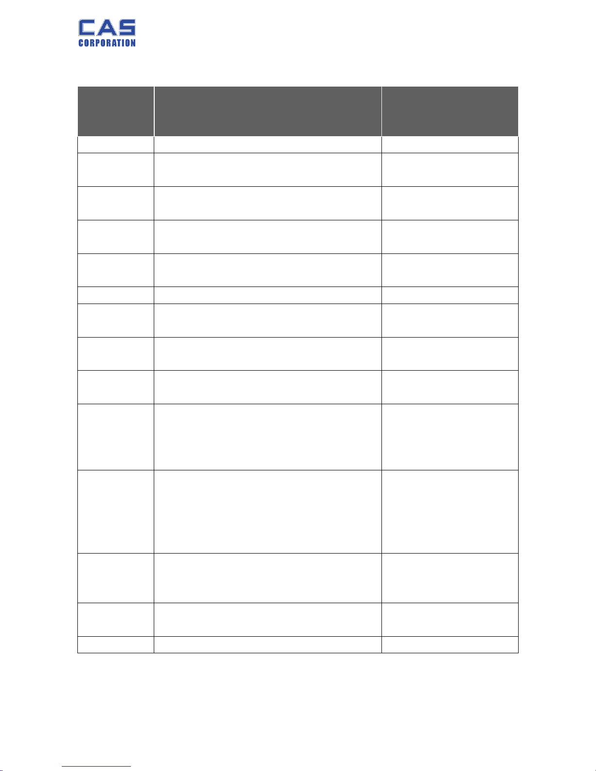
3. Error Messages & Solution
Error
Message
on Display
Description Solution
"Err 0"
The "Err 0" occurs when scale is not stable.
Remove unstable facts.
"Err 1"
The "Err 1" occurs when a current zero point
has shifted from the last span calibration.
Please call your CAS
dealer.
"Err 2"
The "Err 2" is not a real error. Only it prompts
return CAL switch to the normal position.
Please call your CAS
dealer.
"Err 3" The "Err 3" is an overload error.
Please remove the
weight.
"Err 4" The "Err 4" is leakage of payment.
Scale needs more
payment.
"Err 5" The "Err 5" means there is already tare.
Remove the tare.
"Err 6"
The "Err 6" means total price summation is
over.
Please change unit price
or remove some weight.
"Err 7" The "Err 7" means total price is over.
Please change unit price
or remove some weight.
"Err 8" The "Err 8" means Euro rating price is over.
Please change unit price
or change euro rate.
“Err 11”
The "Err 11" means a writing error of the
internal nonvolatile memory. To recognize this
error, be sure to check the voltage on the circuit
and do calibration procedures.
If it still has "Err 11",
replace the digital module.
“Err 12”
The "Err 12" warns that the scale has lost the
parameters for weighing regulations or has lost
the factors for a digital span calculation.
Enter each condition codes
again (?).
Please try a span
calibration again if still not
fixed.
“Err 13” The "Err 13" means the soft key code is broken.
Please try to find out which
key lost soft key code and
then input this code again.
“Err 14”
The "Err 14" means calibration range is not
correct.
Please call your CAS
dealer.
“Err 15” The "Err 15" means 1/2 or 1/4 unit price is over.
Please change unit price
Page 16
PR-T Service Manual
16 8/31/2015
4. The Schematics and Diagram
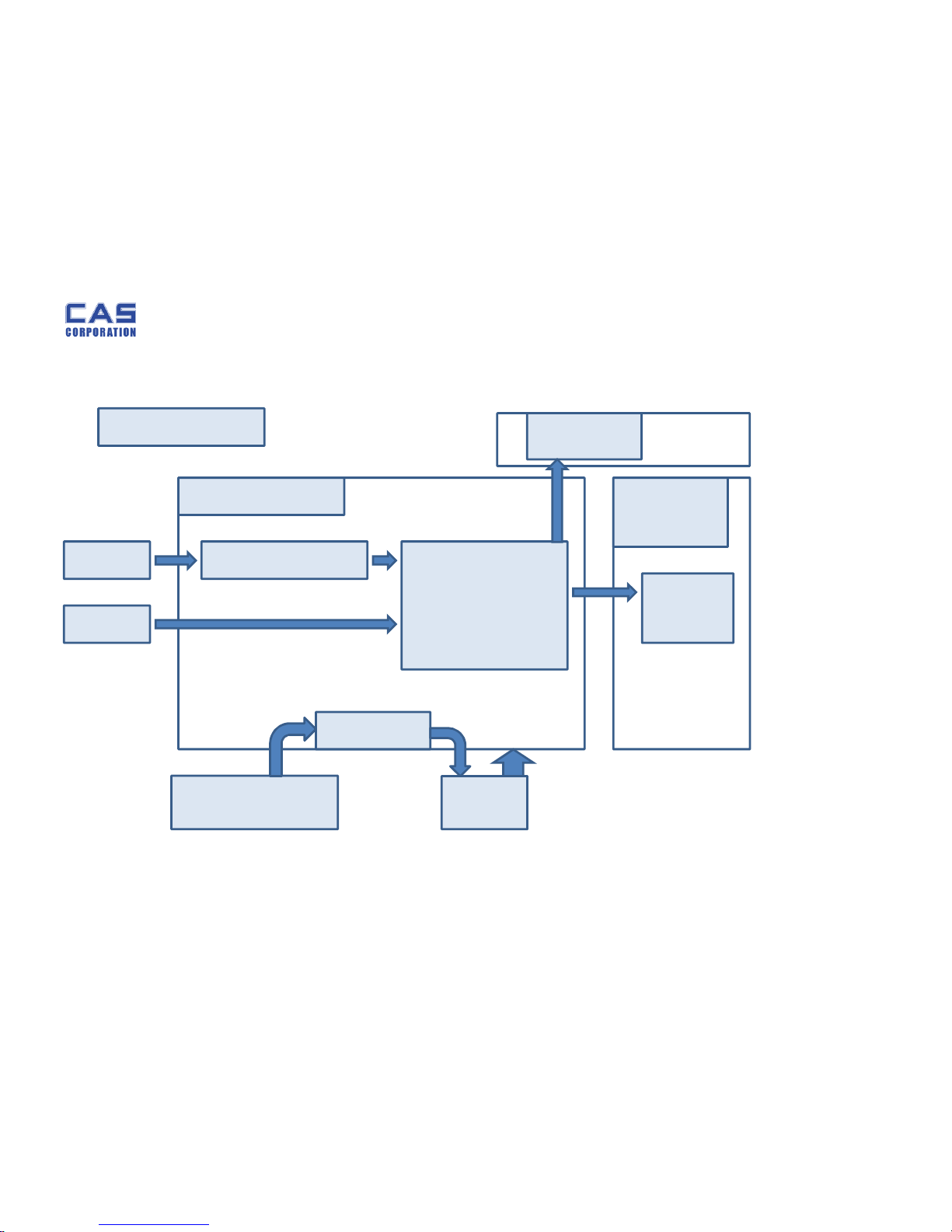
4.1. System Block Diagram
PR-T
MAIN BOARD
LOAD CELL
KEY
AD CONVERTER
MCU
LED
DRIVER
DISPLAY
BOARD
POWER110/220V, 50/60HZ
RECHARGE
PB BAT
PRINTER
MODULE
Page 17
PR-T Service Manual
17 8/31/2015
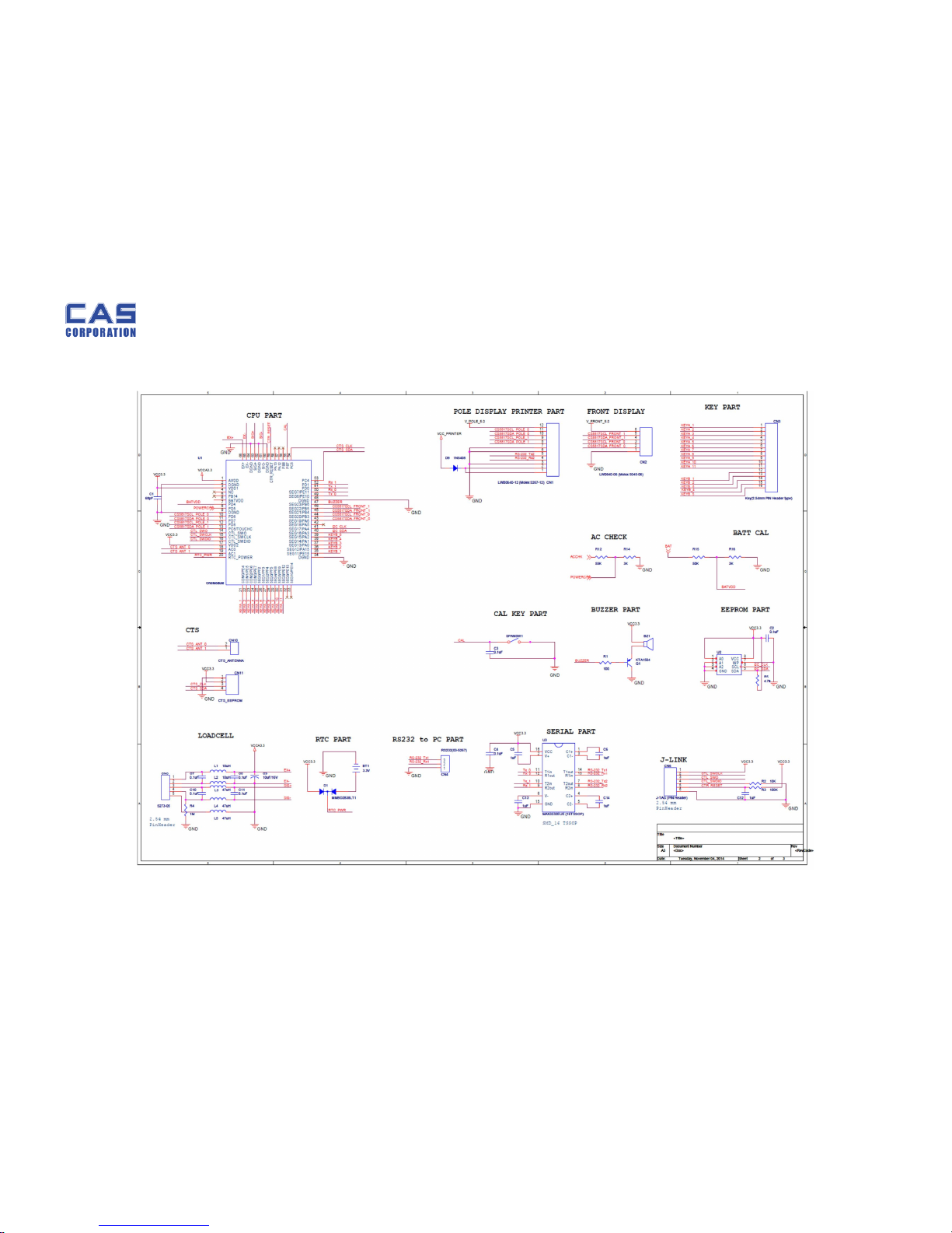
4.2. Circuit Diagram
4.2.1. Main
Page 18
PR-T Service Manual
18 8/31/2015
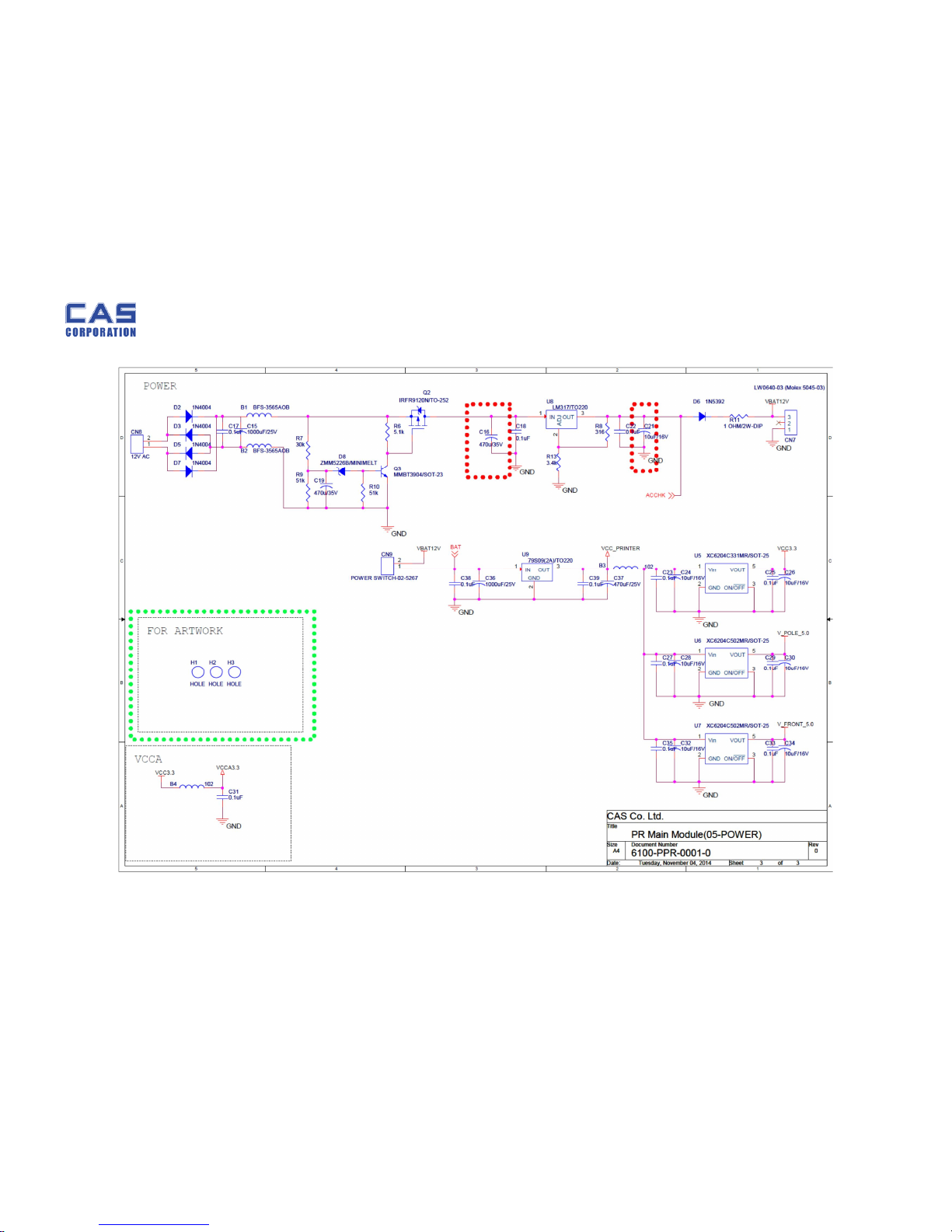
4.2.2. Power Part
Page 19
PR-T Service Manual
19 8/31/2015
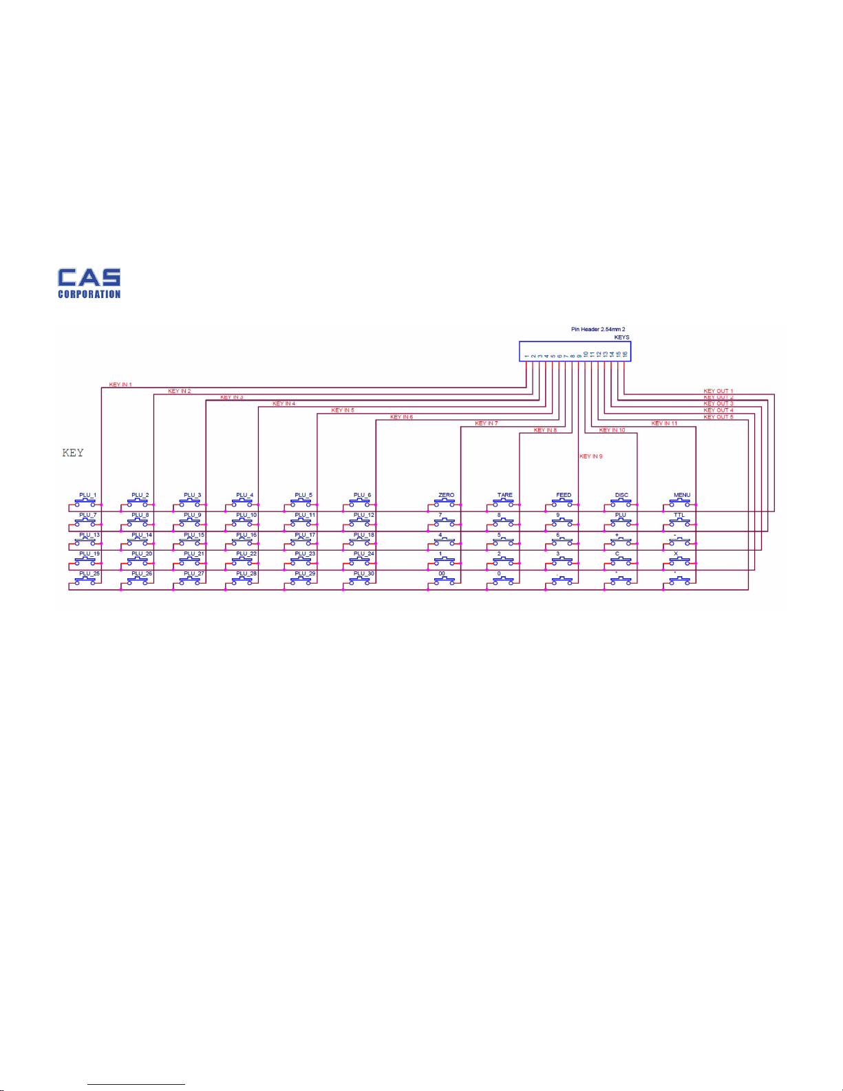
4.2.3. Key Part
Page 20
PR-T Service Manual
20 8/31/2015
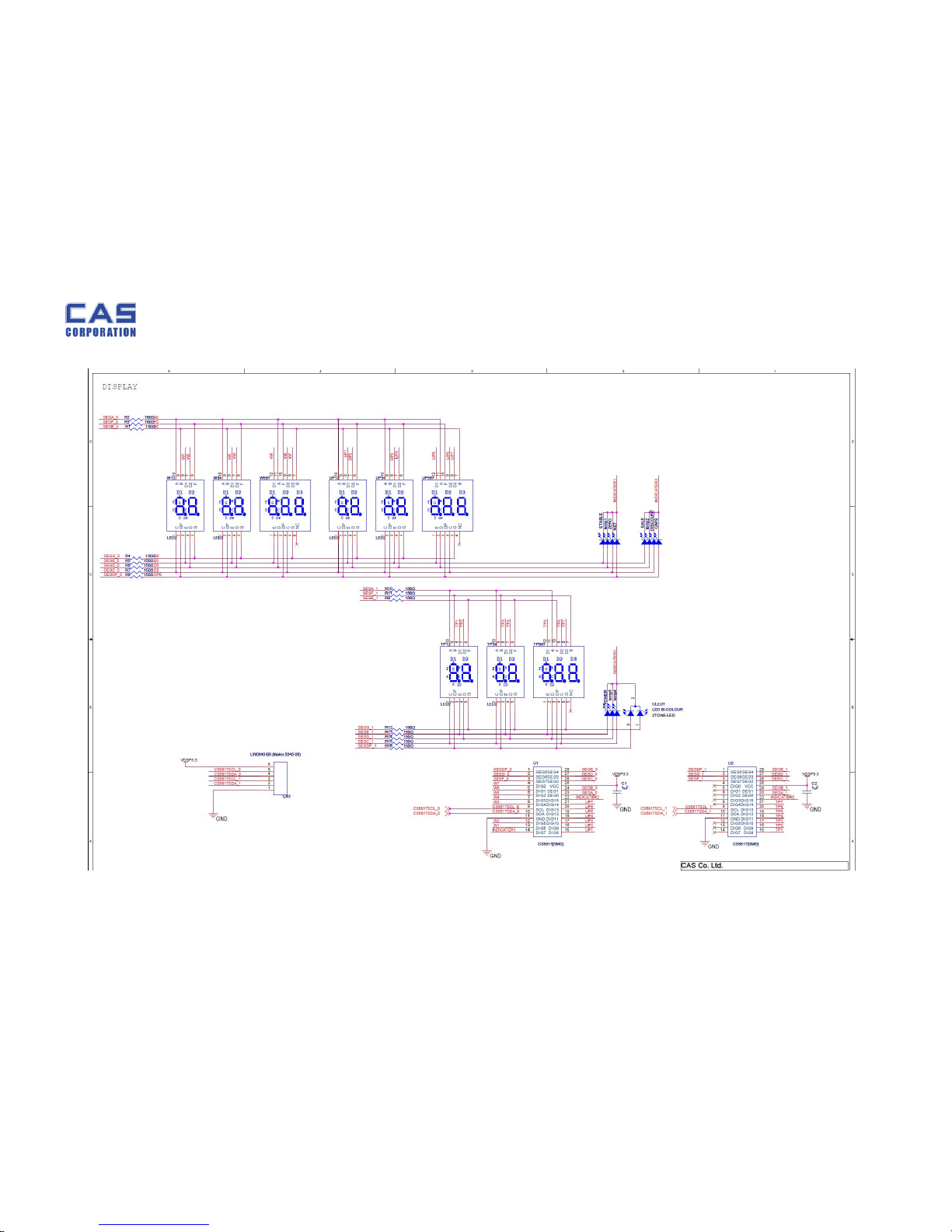
4.2.4. Display Part
Page 21
PR-T Service Manual
21 8/31/2015
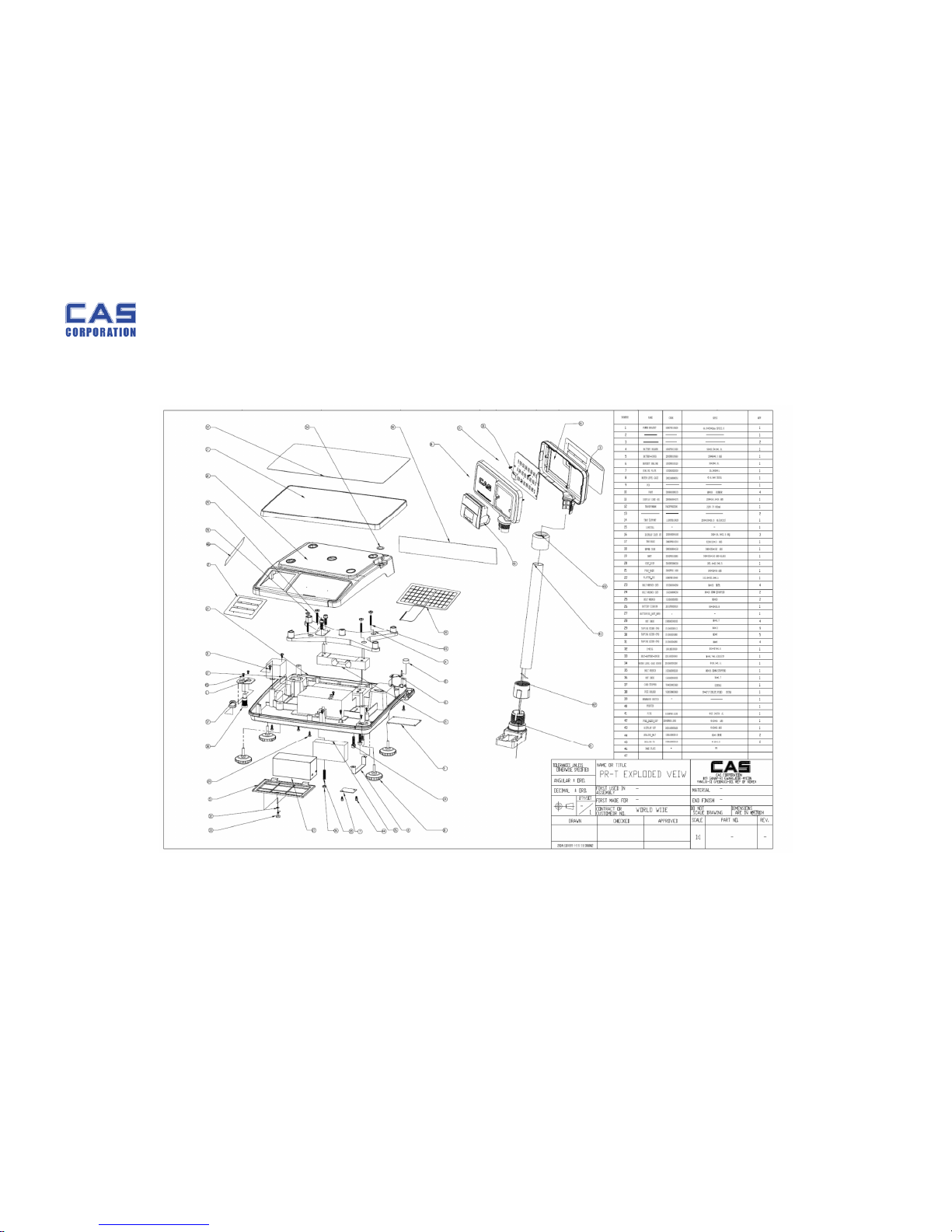
5. Exploded View
5.1. BODY
Page 22
PR-T Service Manual
22 8/31/2015
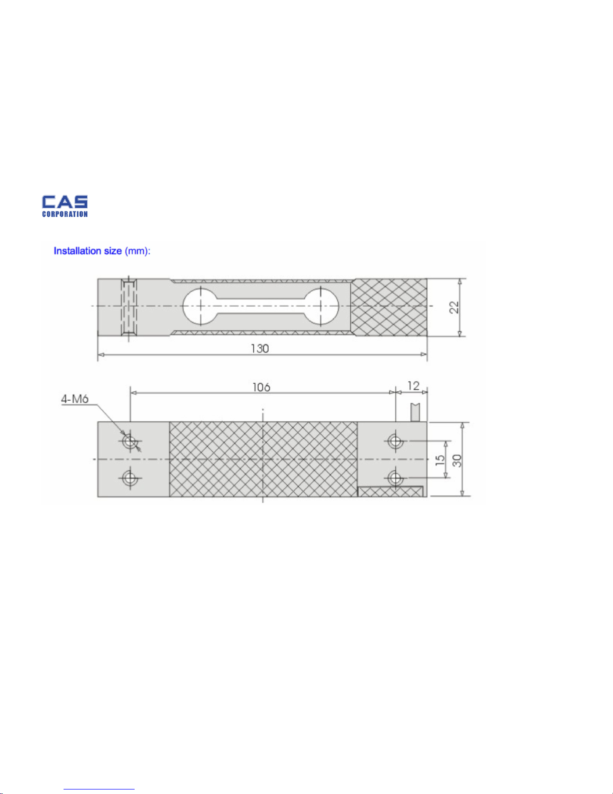
5.2. Load Cell drawing
Page 23
PR-T Service Manual
23 8/31/2015
6. Part
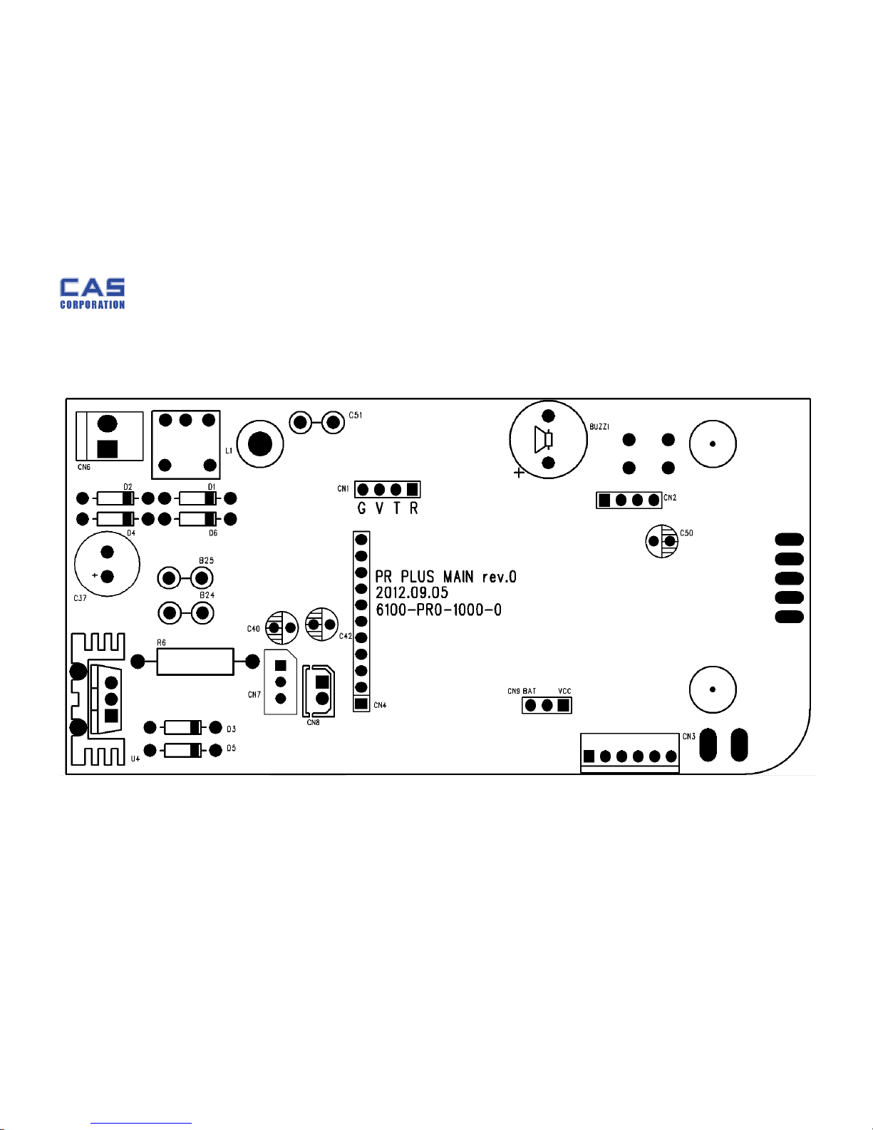
6.1. Part Location
Main PCB (Top)
Page 24
PR-T Service Manual
24 8/31/2015
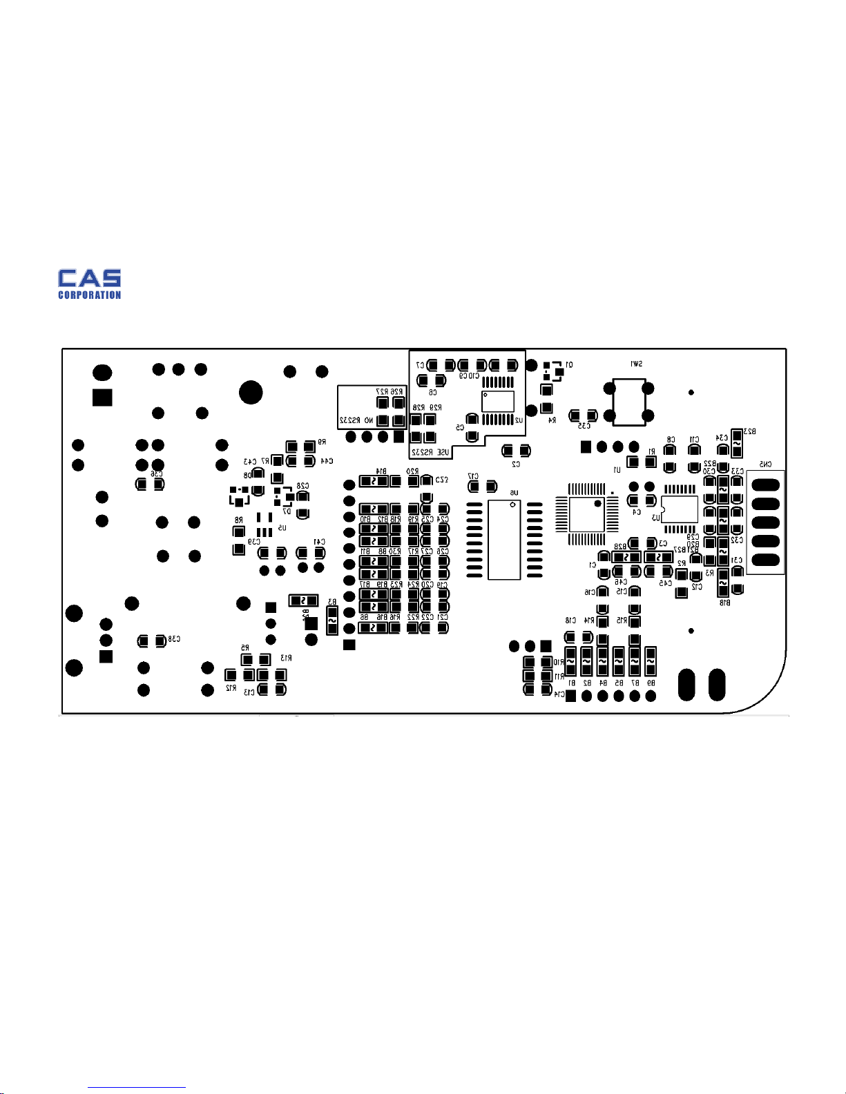
6.1.1. Main PCB (Bottom)
Page 25
PR-T Service Manual
25 8/31/2015
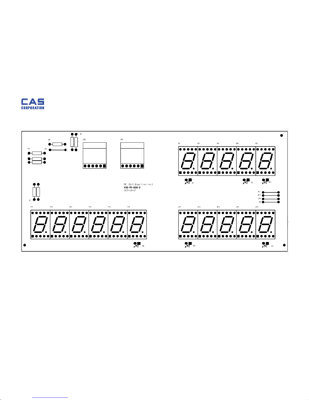
6.1.2. Front Display PCB (Top)
Page 26
PR-T Service Manual
26 8/31/2015
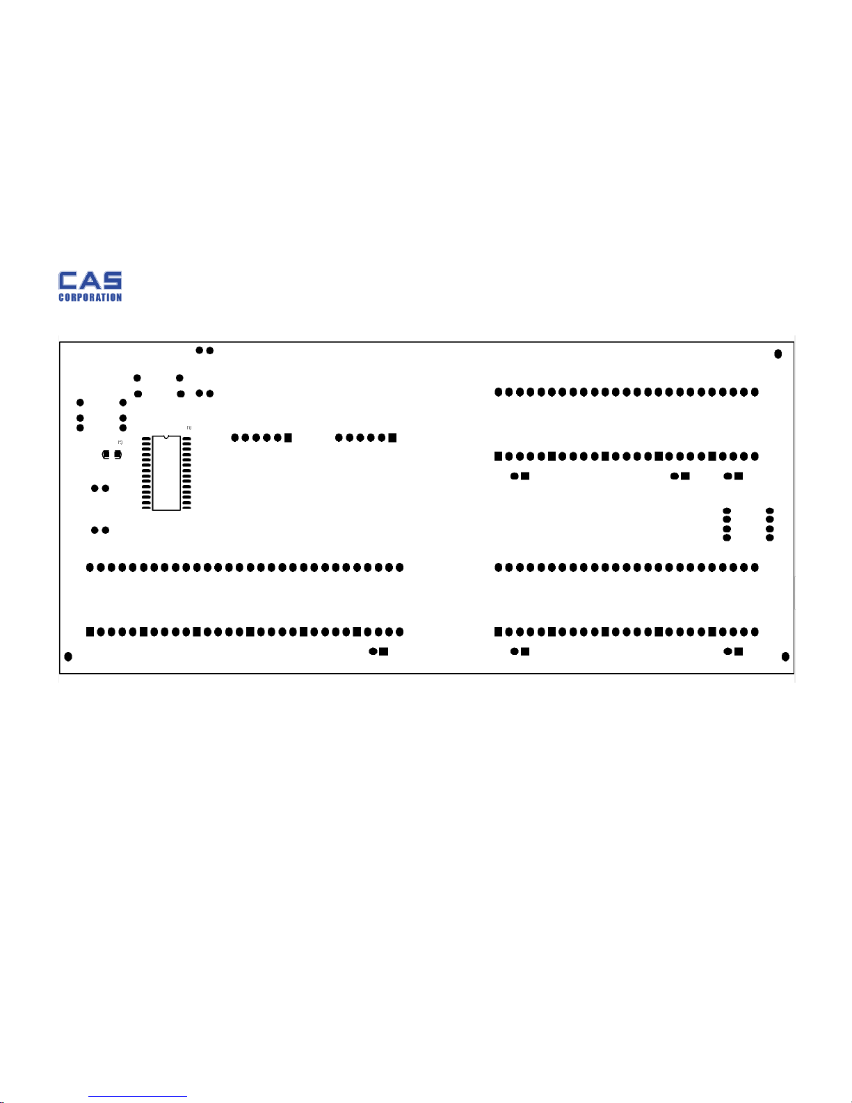
6.1.3. Front Display PCB (Bottom)
Page 27
PR-T Service Manual
27 8/31/2015
6.1.4. Rear Display PCB (Top)
6.1.5. Rear Display PCB (Bottom)
Page 28
PR-T Service Manual
28 8/31/2015
6.1.6. Pole Display PCB (Top)
Page 29
PR-T Service Manual
29 8/31/2015
6.1.7. Pole Display PCB (Bottom)
Page 30
PR-T Service Manual
30 8/31/2015
6.2. Part Order List
A: Electronins Parts
No Order No Part Name Image Remark
1 6R00-PR0-
1000-0
MAIN PCB
2 6R10-PR0-
1000-0
FRONT
DISPLAY
PCB
3 6R10-PR0-
1001-0
REAR
DISPLAY
PCB
4 6R10-PR0-
1002-0
POLE
DISPLAY
PCB
Page 31
PR-T Service Manual
31 8/31/2015
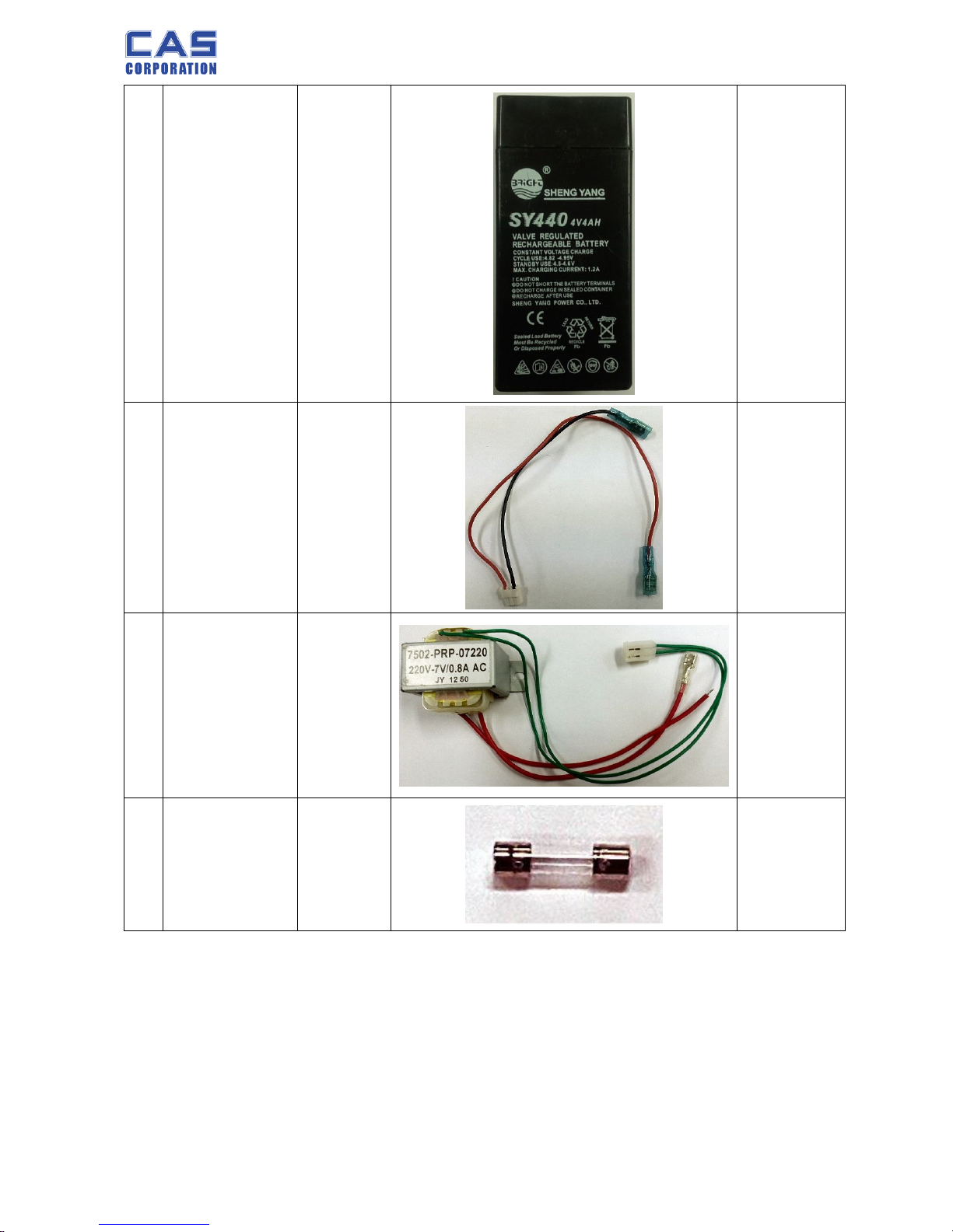
5 7520-P00-
7000-0
BATTERY
102*46.3*4
6.3
(4V/4Ah PB)
6 7840-W00-
3110-0
BATTERY
WIRE
3P*
110/240MM
7 7520-PPR-
0220-0
TRANSFO
RMER
220V 7V
800mA
8 7620-S00-
0100-0
FUSE
250V
100mA
Page 32
PR-T Service Manual
32 8/31/2015
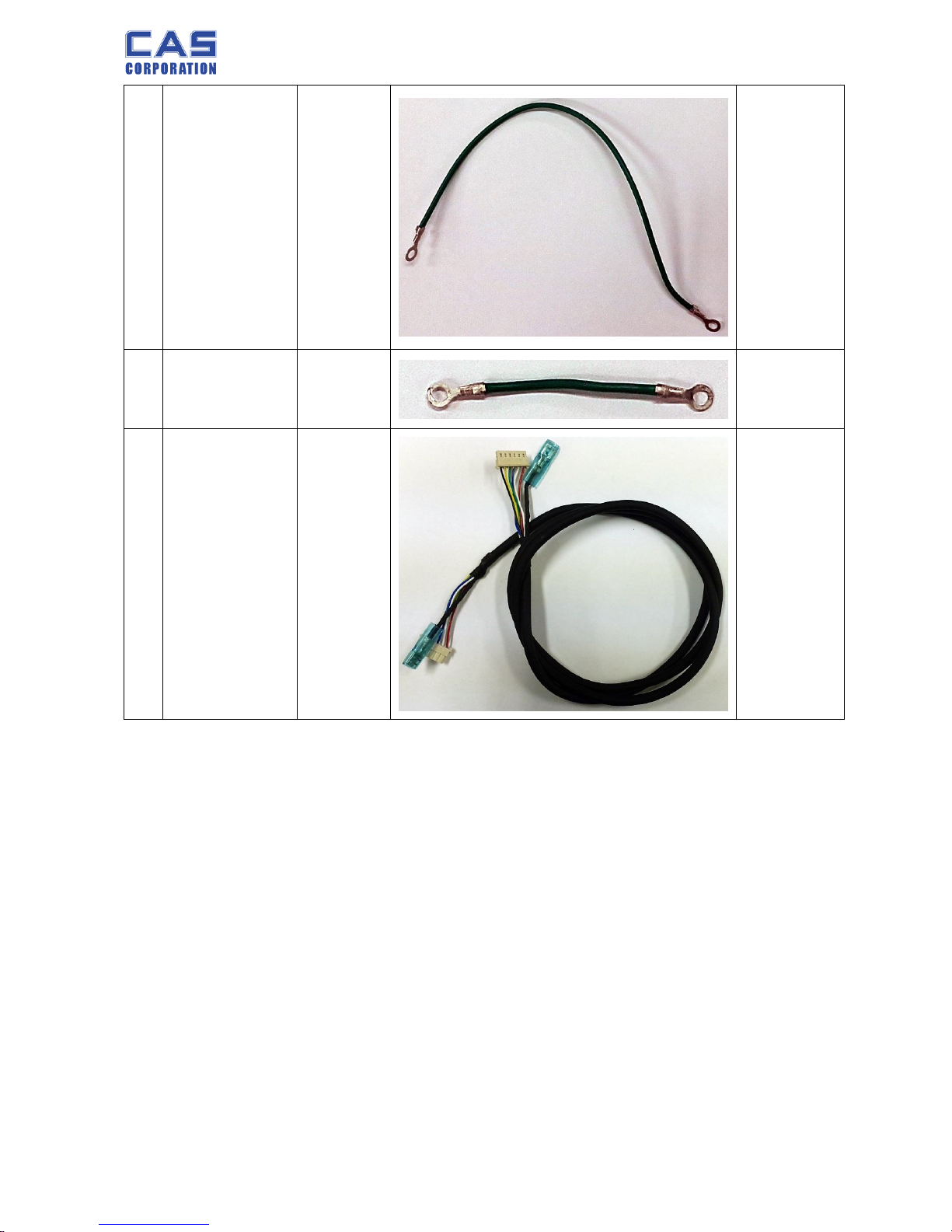
9 7860-GND-
0250-C
GROUND
WIRE
1P*250mm
(GREEN)
10 7860-GND-
0080-0
GROUND
WIRE
1P*80mm
(GREEN)
11 7834W0010200 SHIELD
WIRE
POLE WIRE
(P-type
Only)
Page 33
PR-T Service Manual
33 8/31/2015
B: Mechanics Parts
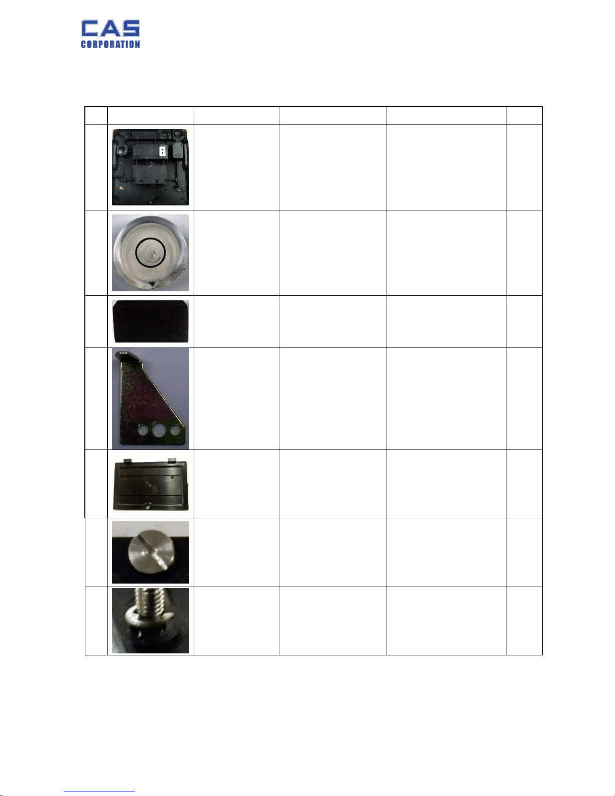
B.1 BODY ASS’Y(B,P TYPE)
NO
IMAGE CODE PART NAME SPEC Q’TY
1
2000-A00-1000-0 BODY
340*335*150
ABS+GLASS
1
2
2022-A00-0005-0 WATER LEVEL GAGE Φ14.5*8 CHINA 1
3
2631-PR0-0001-0 BATTERY CUSHION 85*45*25.8 1
4
1000-A00-1000-0 BRACKET_SEALING 36*20*1.0 1
5
2000-A00-1001-0 BATTERY-COVER 138*96*9.3 ABS 1
6
1261-A00-0004-0
BOLT-BATTERY-
COVER
M4*0.7*8.5(SUS)TP 1
7
1561-MSU-0300-
0
E-RING Φ3*Φ7*0.6 1
Page 34
PR-T Service Manual
34 8/31/2015
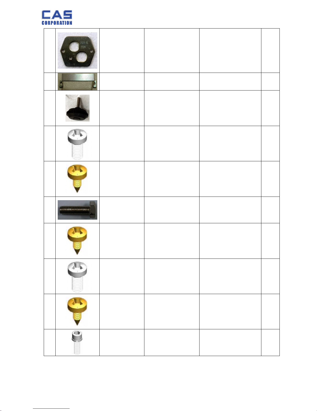
8
1000-A00-1001-0 POWER BRACKET 44.8*39*2MM 1
9
1000-A00-1002-0 BATTERY HOLDER 90*20.5*10*1.0T 1
10
2008-A00-0001-
B
FOOT M6*20 RUBBER 4
11
1502-A00-0308-0 MACHINE SCREW M3*8 2
12
1510-A00-0412-0 TAPPING SCREW (PH) M4*12 10
13
1532-A00-0625-0 BOLT WRENCH (ST)
M6*25 彩锌(STOPPER)
1
14
1510-A00-0412-0 TAPPING SCREW (PH) M4*8 7
15
1502-A00-0308-0 MACHINE SCREW M4*8 1
16
1510-A00-0412-0 TAPPING SCREW (PH) M3*8 7
17
1530-A00-0625-0 BOLT WRENCH
M6*25
2
Page 35
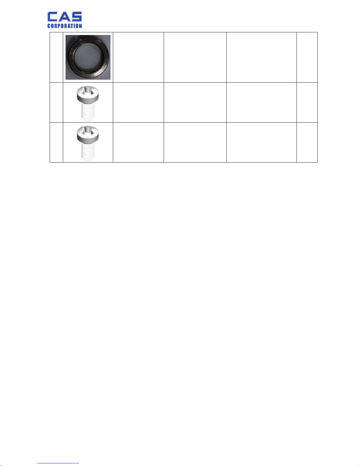
PR-T Service Manual
35 8/31/2015
18
1551-A00-0630-0 WASHER (SPR M6) Φ6.3 2
19
1502-A00-0308-0 SCREW-MACHINE(PH)
M3*8 (외주)(CHINA)
1
20
1502-A00-0406-0 SCREW-MACHINE(PH) M4*6 1
Page 36
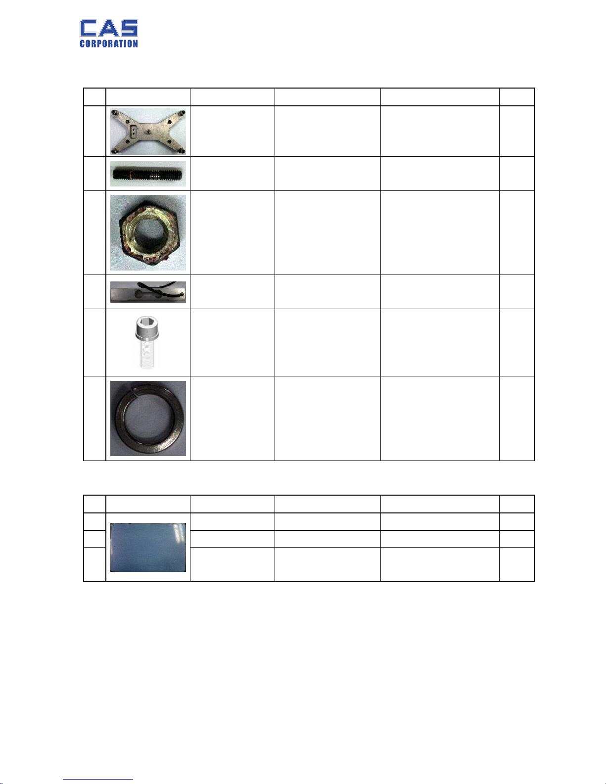
PR-T Service Manual
36 8/31/2015
B.2 L/C BRACKET ASS’Y(B,P TYPE)
NO IMAGE CODE PART NAME SPEC Q’TY
1
1100PR010420 TRAY SUPPORT
250*150*29.5
AL(ADC12)
1
2
1532A0004250 BOLT WRENCH (ST)
M4*25 黑色
4
3
1540A0004000 NUT (HEX) M4*3 4
4
5519PR000300 LOADCELL 130*30*22 1
5
1530MPZ06200 BOLT WRENCH
M6*20
2
6
1551MPZ06000 WASHER (SPR M6) Φ6.3 2
B.3 TRAY BRACKET ASS’Y(B,P TYPE)
NO IMAGE CODE PART NAME SPEC Q’TY
1
2000PR010210
TRAY(ABS) 322*212*13 ABS 1
2
1000PR010320
PLATTER_SUS 313.8*202.8*0.5 SUS430 1
3
8700PR012000
Double Faced Adhesive
Tape
A ROLL 1
Page 37
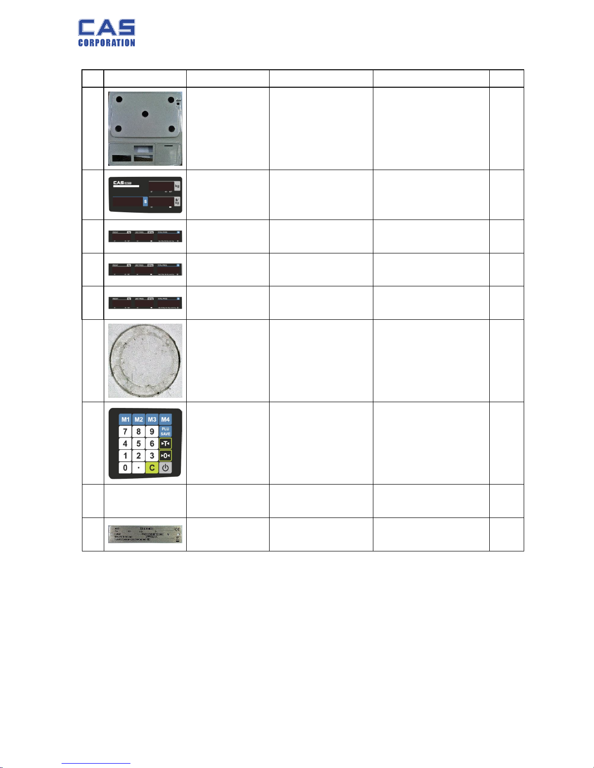
PR-T Service Manual
37 8/31/2015
B.4 BENCH UPPER ASS’Y(B TYPE)
NO IMAGE CODE PART NAME SPEC Q’TY
1
2000A0010020 CASE 340*335*150 ABS 1
2
3050PRA00331
FRONT DISPLAY-
COVER(外销)
195.85*92.7*0.5 1
3
3050PRB06332
REAR DISPLAY-
COVER(外销)
263.4*42.5*0.5 1
4
3050PRB15332
REAR DISPLAY-
COVER(外销)
263.4*42.5*0.5 1
5
3050PRB30332
REAR DISPLAY-
COVER(外销)
263.4*42.5*0.5 1
6
2010A0000260
WATER LEVEL GAGE
COVER
Φ18.5*0.5t 1
7
3100PR000331 MEMBERSWITCH KEY KEY CIRCUIT 1
8
2200PR000CN0
MEMBER SWITCH
KEYSHEET
KEYSHEET 1
9
1810PR000331 SPEC PLATE 97.6*22.7*0.5t 1
Page 38
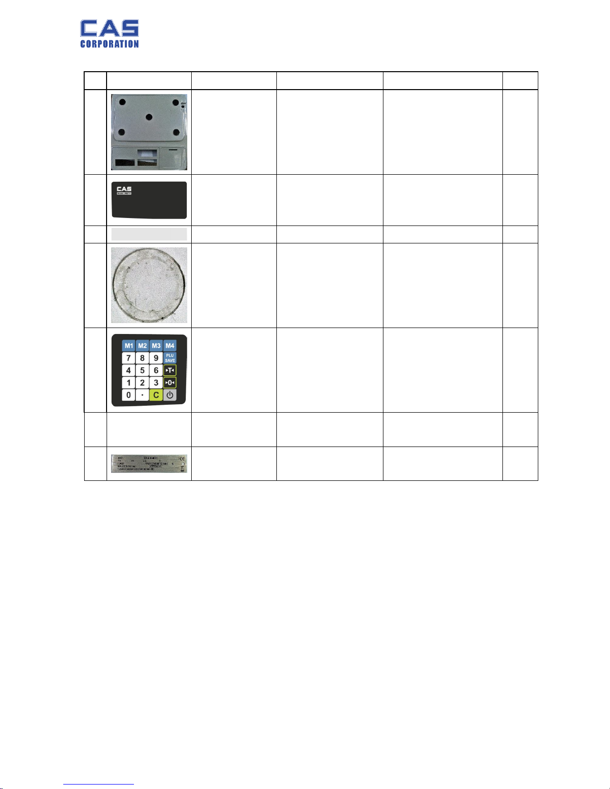
PR-T Service Manual
38 8/31/2015
B.5 POLE UPPER ASS’Y(P TYPE)
NO IMAGE CODE PART NAME SPEC Q’TY
1
2000PR010110 CASE 340*335*150 ABS 1
2
3050PR000331 PR PLUS FRONT DUMP 195.85*92.7*0.5 1
3
2050PRB00330 CUST_DISP 263.4*42.5*0.5 1
4
2010A0000260
WATER LEVEL GAGE
COVER
Φ18.5*0.5t 1
5
3100PR000331 MEMBERSWITCH KEY KEY CIRCUIT 1
6
2200PR000CN0
MEMBER SWITCH
KEYSHEET
KEYSHEET 1
7
1810PR000331 SPEC PLATE 97.6*22.7*0.5t 1
Page 39
PR-T Service Manual
39 8/31/2015
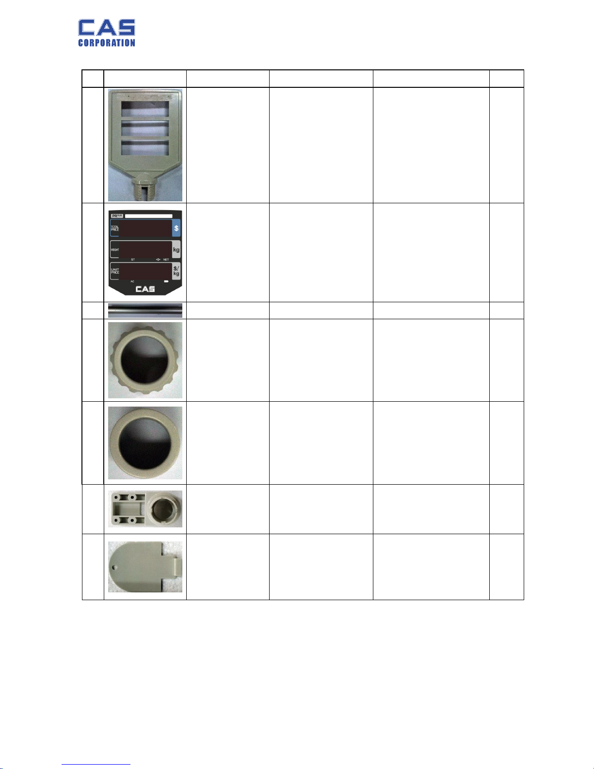
B.6 DISP CASE ASS’Y(P TYPE)
NO IMAGE CODE PART NAME SPEC Q’TY
1
2000PR011180 DISPLAY-CASE
194*136*18.5
ABS
2
2
3050PRR00331
DISPLAY-COVER
(POLE)
135*111.25*1.0 2
3
1150PR011220 PIPE Φ27.2*270 AL 1
4
2001A0000420 DISPLAY NUT Φ43*35 ABS 1
5
2000PR011380 POLE_BASE3_CAP Φ42*34 ABS 1
6
2000PR011480 POLE_BASE 100*50*54 ABS 1
7
2020PR011580 PR POLE CONNECTOR 1
 Loading...