

Page 1

User’s Manual
LINE THERMAL PRINTER
MODEL
DEP-50
VERSION 1.06 / september 2005
Page 2

CONTENTS
1 OUTLINE .................................................................................... 1 3
1.1 Features ............................................................................ 13
1.2 Unpacking ...................................................................... 1 4
2 BASIC SPECIFICATIONS ......................................................... 1 5
2.1 Basic specifications...................................................... 1 5
2.2 Paper Specifications ..................................................... 1 6
3 OUTER APPEARANCE AND COMPONENT PARTS............. 1 8
4 OPERATION............................................................................... 2 0
4.1 Connecting AC Adapter................................................ 2 0
4.2 Connecting Interface Cable ......................................... 2 1
4.3 Inserting the Paper ....................................................... 21
4.4 Eliminating the Paper Jam ............................................ 2 3
4.5 LEDs ...................................................................................24
4.6 FEED Switch Function .................................................. 24
4.7 Paper End Function ....................................................... 2 4
4.8 How to Remove Remaining Paper Roll .................... 24
5 DIP SWITCH SETTING ............................................................ 2 5
5.1 Location of DIP Switch................................................ 2 5
5.2 DIP Switch Function...................................................... 2 5
6 SERIAL INTERFACE CABLE ATTACHMENT ........................ 2 7
6.1 Serial Interface............................................................... 2 7
6.2 Input-output Signals .................................................... 2 7
6.3 Signal Description.......................................................... 2 7
6.4 Dataflow Control ............................................................ 2 7
7 POWER CONNECTOR ............................................................. 2 8
8 COMMAND lIST ........................................................................ 2 9
9 DETAILED DESCRIPTION ........................................................ 3 1
Page 3

Line Thermal Printer DEP-50
4 5
User’s Manual
IMPORTANT SAFETY INSTRUCTIONS
y Read all of these instructions and save them for future reference.
y Follow all warnings and instructions marked on the product.
y Unplug this product from the wall outlet before cleaning. Do not use liquid
or aerosol cleaners. Use a damp cloth for cleaning.
y Do not use this product near water.
y Do not place this product on an unstable cart, stand or table. The product
may fall, causing serious damage to the product.
y Slots and openings on the back or cover these openings. The openings should
never be blocked by placing the product on a bed, sofa, rug of other similar
surface. This product should never be placed near or over a radiator or heater.
This product should not be placed in an built-in installation unless proper
ventilation is provided.
y This product should be operated from the type of power source indicated on
the marking label. If you are not sure of the type of power available, consult
your dealer or local power company.
y Do not allow anything to rest on the power cord. Do not place this product
where the cord will be walked on.
y If an extension cord is used with this product, make sure that the total of the
ampere ratings of the products plugged into the extension cord does not
exceed the extension cord ampere rating. Also, make sure that the total of all
products plugged into the wall outlet does not exceed 15 amperes.
y Never push objects of any kind into this product through cabinet slots as they
may touch dangerous voltage points or short out parts that could result in a risk
of fire or electric shock. Never spill liquid of any kind on the product.
y Except as explained elsewhere in this manual, do not attempt to service this
product by yourself. Opening and removing the covers that are marked “Do
Not Remove” may expose you to dangerous voltage points or other risks.
Refer all servicing on those compartments service to service personnel.
y Unplug this product from the wall outlet and refer servicing to qualified service
personnel under the following conditions:
A. When the power cord or plug is damaged or frayed.
B. If liquid has been spilled into the product.
Page 4
Line Thermal Printer DEP-50
6 7
User’s Manual
SAFETY PRECAUTIONS – BE SURE TO OBSERVE
In order to prevent hazards to an operator or other persons and
damage to property, be sure to observe the following precautions.
y The following describes the degrees of hazards and damages that
can occur if the given instructions are neglected or the printer is
incorrectly operated.
WARNING
Negligence of this precaution may result in death or serious injury.
CAUTION
Negligence of this precaution may result in injury or damage to
property.
This is an illustration mark used to alert your attention.
This is an illustration mark used to indicate such information
as an instruction or the like.
CAUTIONS
y Prior to using the equipment, be sure to read this User’s Manual thoroughly.
Please keep it handy for reference whenever it may be needed.
y The information contained herein may be changed without prior notice.
y Reproduction of part or all of this User’s Manual without permission is
strictly prohibited.
y Never service, disassemble, or repair parts that are not mentioned
in this User’s Manual.
y Note that we will not be responsible for damages attributable to a user’s
incorrect operation/handling or an improper operating environment .
y Operate the equipment only as described in this User’s Manual; otherwise
accidents or problems may result.
y Data are basically temporaty; they cannot be stored or saved permanently or
for a long time. Please note that we will not be responsible for damages or
sses of profit resulting from losses of the data attributable to accidents,
repairs, tests, and so on.
y If you have any questions or notice any clerical errors or omissions regarding
the information in this manual, please contact our office.
y Please note that, notwithstanding them 8 above, we will not be responsible for
any effects resulting from operation of the equipment.
!
!
!
i
C. If the product has been exposed to rain or water.
D. If the product does not operate normally when the operating instructions
are followed. Adjust only those controls that are covered be the operating
instructions since improper adjustment of other controls may result in
damage and will often require extensive work by a qualified technician to
restore the product to normal operation.
E. If the product has been dropped or the cabinet has been damaged.
F. If the product exhibits a distinct change in performance, indicating a need
for service.
y Please keep the poly bag which this equipment is packed in away from
children or throw it away from children or throw it away to prevent
children from putting it on. Putting it on may cause suffocation.
Page 5
Line Thermal Printer DEP-50
8 9
User’s Manual
PRECAUTIONS FOR INSTALLATION
y Do not use or store the equipment in a place exposed to fire, moisture, or direct
sunshine, or in a place near a heater or thermal device where the prescribed
operating temperature and humidity are not met, or in a place exposed to
much oil, iron powder, or dust. The equipment may become out of order, emit
smoke, or catch fire.
y Do not install or use the equipment in a place like a laboratory where chemical
reactions are expected, or in a place where salt or gases are contained in the
air. There is a danger of fire or electric shock.
y Install the printer on a flat, stable desk or table that is free from vibration, in a
well-ventilated place.
y Do not install the printer at a location where its operation could be hindered.
y Do not place anything on the printer or leave small objects, like a clip or pin,
around it. A foreign object could cause trouble if it gets inside.
y Do not use any sharp-pointed object, such as a pen, for example, to touch the
operation panel of the printer. It could cause trouble.
y Do not use the equipment near a radio or TV receiver. Do not share the power
from a plug socket a radio or TV receiver is connected to. It may cause a
reception problem.
y Use the equipment only at the specified power supply, voltage and frequency.
Otherwise, it may emit smoke and catch fire or cause other problems.
y Connect only the specified power source. Use of an unspecified power source
could cause trouble or smoke/fire.
y Confirm that a plug socket used for connection has sufficient capacity.
y Avoid connecting a power cable to a plug socket shared by other devices or
extending the wiring too far. It may result in the cable catching fire or a power
outage. Also, do not step on or apply an excessive force (Pull, Load) to the
cable, and do not use the printer with such a force applied to it.
y Never connect a grounding cable (Frame ground) to a gas pipe. There is a
danger of explosion. When connecting or disconnecting the grounding cable,be
sure to disconnect the power cable and the power plug from the plug socket.
y When connecting/disconnecting the cables, be sure to turn off the power first,
including the connected side, and then connect/disconnect them, holding a
plug and a connector. Pulling the cable itself could cause it to snap or become
damaged.
y Connect a power cable or a connector cable securely. If a reverse-polarity
connection is a made, internal elements may be broken or a mating device
may be ad versely affected.
WARNING
y
Never handle the equipment in the following manners, as it may break, become out of
order, or overheat causing smoke and resulting in fire or electric shock. If the equip
ment is used in an abnormal condition, such as when broken, then problems, smoke
emission, abnormal odor/noise, and fire can result. If an abnormal condition exists, be
sure to disconnect the power plug from a plug socket, and contact our dealer. Never
repair the equipment on your own – it is very dangerous.
y Do not allow the equipment to receive a strong impact or shock, such as
kicking, stamping, hitting, dropping, and the like.
y Install the equipment in a well-ventilated place. Do not use it in such a manner
that its ventilation port will be blocked.
y Do not install the equipment in a place like a laboratory where chemical reactions
are expected, or in a place where salt or gases are contained in the air.
y Do not connect/disconnect a power cord or a data cable, while holding the
cable.
y Do not pull, install, use, or carry the equipment in such a manner that force will
be applied to the cables.
y Do not drop or insert any foreign substances, such as clips or pins, into the
equipment.
y Do not spill any liquid or spray any chemical-containing liquid over the
equipment. If any liquid is spilled on it, turn off power, disconnect the power
cable and power cord from the plug socket, and contract our dealer.
y Never disassemble or remodel the equipment. Negligence of this may cause
fire or electric shock.
y Use the equipment only with the specified commercial power supply and AC
adapter. Negligence of this may result in fire, electric shock, or problems.
y If you drop or break the AC adapter, or if water or the like gets inside it, unplug
it immediately from the socket and contact your dealer.
y Do not damage, break, process, bend/pull by force, twist, or head an AC
adapter cord. Also, do not put a heavy substance on it or heat it. The AC
adapter cord could be broken, resulting in fire, electric shock, or trouble. If the
AC adapter cord is damaged, contact our dealer.
y Do not connect/disconnect the AC adapter with wet hands.
y Do not overload a single electrical outlet, using a table tap or a current tap socket.
y An equipment packing bag must be discarded or kept away from children.
A child can suffocate if the bag is placed over the head.
!
!
Page 6
Line Thermal Printer DEP-50
10 11
User’s Manual
PRECAUTIONS FOR HANDLING
Do not handle the equipment in the following manners, because problems
may result.
y Do not use any other power source besides the accessory AC adapter. Also,
do not use the AC adapter for other purposes.
y Do not print without paper.
y Do not drop or put any foreign object, such as a clip, pin, or the like, inside the
printer.
y Do not spill any liquid or spray any chemical-containing liquid over the
equipment.
y Never use a pointed object, such as a pen, to operate the operation panel.
y Do not use Scotch tape to fasten paper together for continuous use. It could
damage the printing head.
y Never pull the set paper forcibly. When opening/closing the printer cover,
take care that the paper will not be caught. It could cause the paper to jam.
y Be sure to use the specified paper. Use of other paper could deteriorate the
print quality or cause a problem with the printing head.
To Prevent and Spreading of Damage
y Never touch the printing head motor, or paper cutting blade. Your finger may
be cut.
y During power-on or immediately after printing, do not touch electrical parts or
moving parts, such as the mechanism, motor, internal dear, etc. They may be
very hot and can burn your hand/finger.
y Be careful to avoid bodily injure or damaging other objects with an edge of
sheet metal.
y Should any error occur while operating the equipment, stop it immediately
and disconnect the power plug from the plug socket.
y Only a qualified serviceman is allowed to disassemble or repair the printer.
y Should a problem occur, leave solving it to our serviceman. Do not
disassemble the equipment on your own.
y When opening/closing the printer cover, and so on, be careful not to catch
your hand or finger on the equipment.
y After using the equipment, turn off the power switch and unplug the AC
adapter from a plug socket.
y Use a shielding wire or twisted pair wire for a signal line, in order to minimize
noise effect. Do not route the cable too long or connect it to a noisy device.
Connection to a noisy device could cause erroneous printing due to corrupt
data, and so on.
y Use the equipment in an environment where there is s plug socket near the
main body and you can easily disconnect the power plug from it, to shut off the
power.
y When the equipment will not be used for a long period of time, unplug it and
remove the paper roll from it.
y When transporting the equipment, remove the paper roll from paper holder.
!
Page 7
Line Thermal Printer DEP-50
12 13
User’s Manual
DAILY MAINTENANCE
y At the time of maintenance, be sure to turn off the power switch of the printer
and unplug it from the socket.
y Use a dry soft cloth to wipe off stains and dust from the surfaces of the main
body case. For severe soiling, dip the cloth in water and wring it, for wiping off
the soil. Never use organic solvents, such as alcohol, thinner, trichlene,
benzene, ketone, or chemical dusters.
y If the equipment is contaminated with paper powder, use a soft brush
to clean it. Be careful not to damage the printing head.
y Cleaning the Printing Head
1. Referring to “4.4 Eliminating the Paper Jam”, detach the platen roller unit.
2. Moisten gauze slightly with alcohol, and clean the heating surface of the
printing head with it.
3. Reattach the platen roller unit.
The printing head and motor are very hot. Be careful not to tou ch
them immediately after printing. Do not touch the heating surfa ce
of the head with a bare hand or metal. When detaching or reattaching the platen roller unit, be sure to raise up the printing head,
otherwise, they could be damaged. Handle the detached platen
roller unit carefully so as not to damage it.
!
CAUTION
i
1. OUTLINE
The DEP-50 is a compact-sized, line thermal printer developed for variety of applications. It can be used as a data communication terminal,
POS terminal, kitchen terminal, etc.
1.1 Features
It can be used in variety of applications because:
y It is compact and light
y The thermal printing mechanism combines both high speed and
low noise printing
y It has high exploitation reliability due to the mechanical endurance
of the thermal printing head
y Prints variety of barcodes
y There is an independent power supply (AC adapter)
Page 8
Line Thermal Printer DEP-50
14 15
User’s Manual
2. BASIC SPECIFICATIONS
2.1 Basic specifications
1.2 Unpacking
When unpacking the package, confirm that the following parts are provided:
y Printer body ................................. 1 unit
y Sample paper roll ........................ 1 roll
y AC adapter................................... 1 piece
y User’s manual ............................. 1 copy
y Disc ...............................................1 piece
y Install the printer body on a flat and stable desk or mount it onto
the wall, etc., using a hook, etc.
y Do not install the printer near a heater or in a place exposed to
the direct sunshine.
y Do not use the printer in a high-temperature, high-humidity, or
contaminated environment.
y Do not allow dew condensation to form on the printer. If such
condensation should form, do not turn on the power until it has
completely gone away.
y Use only the accessory AC adapter. Do not use it for any other
purpose.
y If you do not use the printer for a long period, disconnect the
power cable from the socket.
y Keep this manual carefully at hand for ready reference.
Printing system Line thermal dot printing
Printing width 48 mm (384 dots/line)
Dot density 8 dots/mm (Width, Length)
Paper feed pitch 0.125 mm
Printing speed up to 50 mm/s
Character size 12×24, 9×16, 24×24 (only for asian versions)
Character types Alphanumerals, symbols, international characters
(Choose from 20 countries)
Barcode type UPC-A/E, JAN(EAN) 13-/8-column, ITF, CODE 39, CODE 93,
CODE 128, CODABAR, PDF417
Paper Thermal paper roll: 58 + 0/- 1 mm ×
φ
83 (max) mm,
60~75 µm thick
Thermal label paper: 58 + 0/- 1 mm ×
φ
83 (max),
150 µm thick (max)
(L and M Spec. only) Label width: 56 mm (max)
Label length: 25 mm/sh. (min)
Interface Serial (RS-232C), Parallel (CENTRONICS compliant)
Input buffer 16 KB
Download characters To downloaded fonts: 12×24, 9×16
AC adapter Rated input : 100~240 V, 50/60 Hz, 40 VA
Rated output : 12 V DC, 2,5 A
Power consumption At non-printing: Approx. 2 W
At printing: Approx. 15 W (approx. 20 W at maximum)
Weight Main body: Approx. 600 g (Paper roll excluded)
AC adapter: Approx. 350 g
Outer dimensions 106 (W) × 184 (D) × 110 (H) mm
Operating temperature 5~400C, 35~85 % RH (No dew condensation)
and humidity
Storage temperature -20~600C, 10~90% RH (No dew condensation)
and humidity
Reliability Printing head life: (250C)
Pulse resistance: 50 million pulses or more (Print rate 12.5%)
Wear resistance: 50 km or more (With recommended
thermal paper at normal temperature and humidity)
!
CAUTION
Page 9
Line Thermal Printer DEP-50
16 17
User’s Manual
2.2 Paper Specifications
2.2.1 Recommended Paper
y Thermal paper roll
y Type: Thermal paper
y Paper width: 58 + 0/–1 mm
y Paper thickness: 60~75µm
y Roll diameter: φ 83 mm or less
y Printing surface: Outside of the roll (Surface)
y Recommended paper: TF50KS-E2C (Monochrome) made by NIPPON SEISHI
or its equivalent 735FA (2-color, Black based) made by RICOH or its equivalen
PB670 (2-color, Red based) made by MITSUBISHI SEISHI or its equivalent
y Core: φ 12 mm (Inner dia.), φ18 mm (Outer dia.)
!
CAUTION
y Use of non-specified paper may cause irregularity of print density.
y Do not paste the paper to the core.
y If the paper comes in contact with a chemical or oil, it may discolor or lose a
record.
y Do not rub the paper surface strongly with a nail or hard metal. It may discolor.
y Discoloring starts at about 70
0
C. Watch out for effects of heat, humidity, light,
and so on.
y Do not use the label paper when the printer has been set for thermal paper,
and vice versa. Be careful not to mistake a type of label paper. It could cause
malfunctioning or damage the printing head.
2.2.2 Recommended Paper
Thermal paper
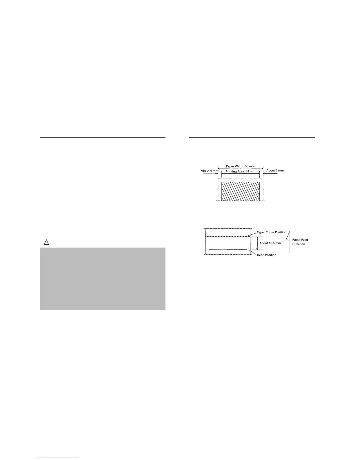
2.2.3 Printing Head and Paper Cutter Layout
Page 10
Line Thermal Printer DEP-50
18 19
User’s Manual
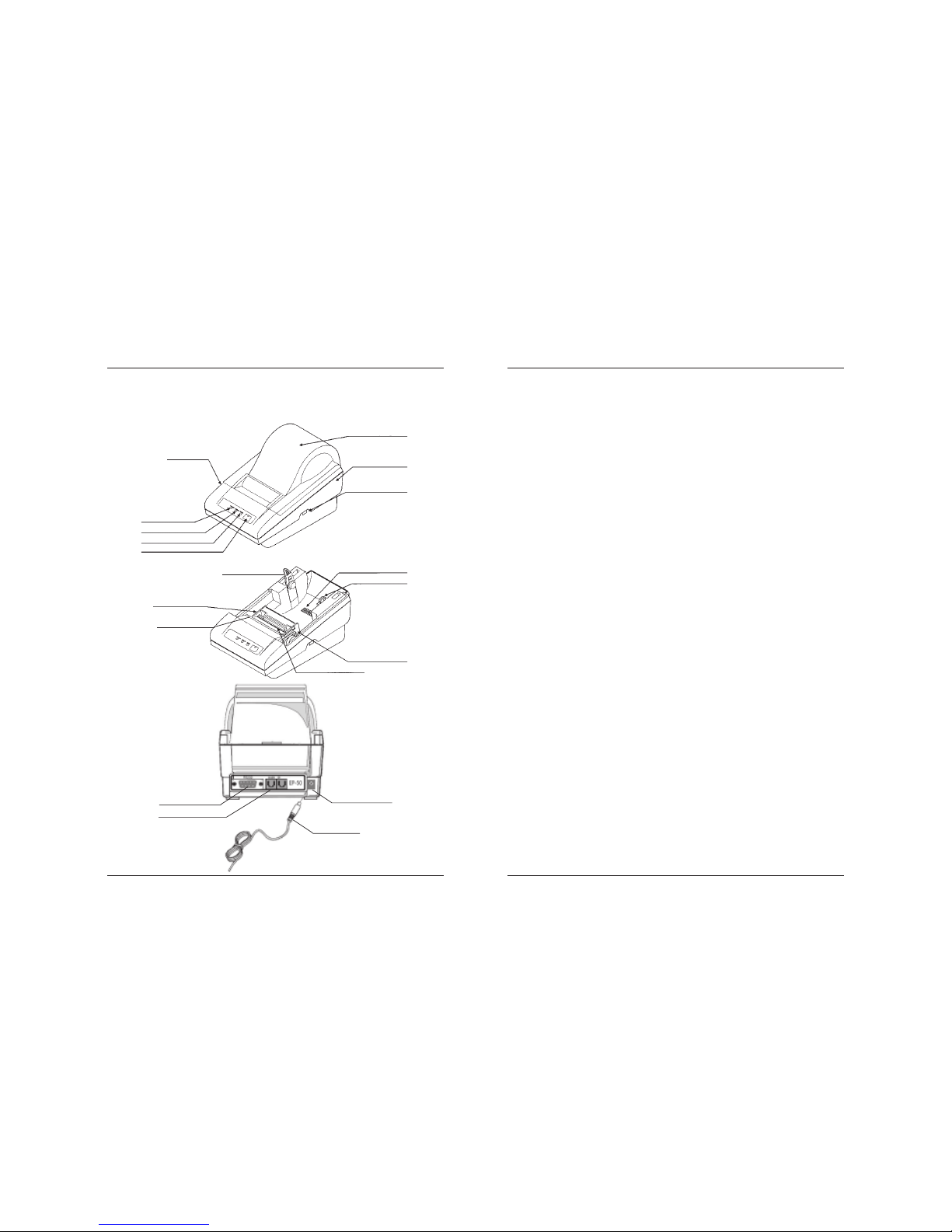
3. OUTER APPEARANCE AND COMPONENT PARTS
(1) POWER switch
Turns on/off the power for the printer body.
(2 ) POWER lamp
Lights green when the printer is switched on
(3 ) ERROR lamp
Flashes red when the printing head is overheated.
(4 ) PAPER lamp
Flashes red when the printer is out of paper, lights red constantly if the paper is
put, but the lever is not pushed down.
(5) FEED switch (Button LF)
Feeds the paper. It is fed continuously while the switch is held down.
(6) Paper holder
Set the paper roll in this holder.
(7) PNE sensor
Detects that the paper is running out.
(8) DIP switch
Initially sets the printer at power-on and sets the functions.
(9) Platen roller unit
Detach this unit when the paper is jamming or when you clean the head.
(10) Head-up lever
Used when replacing the paper or detaching/reattaching the platen roller unit.
(11) Paper cutter
Cuts the printed paper.
(12) Power connector
Connects to the accessory AC adapter.
(13) Interface connector
Connects to a communication interface cable.
(14) Printer cover
Detach this cover when replacing the paper.
(13) RS232 Interface
Drawer Control
AC adapter
(12)Power Conector
(2) Power Lamp
Upper Cover
(3) Error Lamp
(4) Paper Lamp
(5) Weed Switch
(14) Printer Cover
Bottom Cover
(1) Power Switch
(8) DIP Switch
(6) Paper Holder
(10) Head-up-Lever
(9) Platen Roller Unit
Printer Mehanism
(11) Paper Cutter
(7) PNE Sensor
Page 11

Line Thermal Printer DEP-50
20 21
User’s Manual
4. OPERATION
4.1 Connecting AC Adapter
!
CAUTION
y Use only the specified AC adapter.
y When disconnecting/reconnecting the cable connector of the AC adapter,
be sure to hold the connector.
y Separate the AC adapter from other noise-generating devices.
y Pulling the AC power cord may damage it, resulting in a fire, electric shock,
or snapping.
y If a thunder/lightning storm is nearby, disconnect the AC adapter from the
socket and do not use the printer, because a fire or electric shock may occur.
y Do not put the AC power cord close to a heating device.
Its coating can mel and cause a fire or electric shock.
y Install the printer in a well-ventilated place, because the AC adapter
generates heat when it is used.
y Use the specified AC power source. Connect to a power source with sufficient
capacity. If the capacity is insufficient, a fire may result from heat generation.
y After using the printer or when not using it for a long period of time, be sure
to unplug the AC adapter from a plug socket for your safety.
4.2 Connecting Interface Cable
1 Turn off the power. (Mating side included)
2 Check the top and bottom of cable terminals, and connect to the interface
connector.
3 Connect the cable to the host computer.
4.3 Inserting the Paper
!
CAUTION
1 Hold the convexity on the rear of the printer cover, and raise it upward.
2 Cut the front end of the paper roll almost at a right angle.
3 Make sure that the power is turned on.
4 Pull the head-up level to this side to raise up the printing head.
5 If there is still some paper remaining after a paper-out indication, eliminate
the paper roll according to “4.8 How to Remove Remaining Paper Roll.”
6 Insert the front end of the paper roll straight into a paper insertion slot.
7 Set the paper roll firmly in the paper holder.
8 Put back the head-up lever. The paper roll is automatically puiied in by the platen
roller to feed a constant amount of paper. (When auto-loading is enabled.)
9 Put back the printer cover.
y Be sure to use the specified paper roll.
y Use of non-specified peper may not guarantee the print quality, printing
head life, and so on.
1 Turn off the power.
2 Connect the cable connector of the AC adapter
to the power connector located on the back
of the printer.
3 Connect the AC power cord of the AC adapter,
and plug it into a socket.
Page 12
Line Thermal Printer DEP-50
22 23
User’s Manual
!
CAUTION
!
CAUTION
y The printer cover is not stationary (Opening/Closing). After detaching it,
be careful not to lose or break it
y Do not insert a ragged or dog-eared end of the paper roll, because it could
result in a paper jam or insertion error.
y If the paper roll is still slack, rewind the paper to remove the slack
y If the paper roll is tilted, rais the head-up lever to correct the paper roll
posotion, or pull out the paper roll and set it again.
y Do not open the printer cover while printing.
y Do not hold or press the paper roll while printing, because it could cause a
paper jam.
y After the paper is set, the printer is made ready to start printing. Note that if
data is remaining in the buffer, the printer will start printing after the paper is set.
y Do not run the printer with its cover removed, because it could cause
malfunctioning or an irregularity of the sensor.
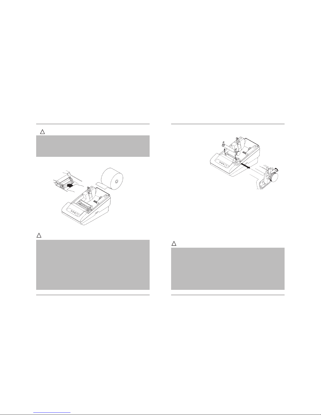
4.4 Eliminating the Paper Jam
y Do not carry out this work just after printing because the printing head is very hot.
y Be sure to turn off the power when detaching the platen roller unit.
y When eliminating remaining paper, do not touch the heating surface of the
head with a bare hand or metal piece.
y Do not detach the platen roller unit unless necessary, such as for a paper jam.
y When putting back the platen roller unit, be sure to confirm that it is correctly
reattached.
y Never detach or reattach the platen roller unit with the head-up lever lowered.
!
CAUTION
1 Turn off the power.
2 Detach the printer cover.
3 Cut the paper roll near the paper insertion slot.
4 Raise the head-up lever.
5 Raise the blue levers located on both sides of the platen roller unit, to gently
detach the unit. The platen roller unit can be detached by manually raising
the blue levers.
6 Remove the remaining paper roll completely from the paper passage.
7 Confirming the direction of the platen roller unit, reattach it to the mechanism.
Shift down the blue levers on both sides, to fix the unit.
8 Lower the head-up lever.
Page 13
Line Thermal Printer DEP-50
24 25
User’s Manual
4.5 LEDs
POWER Lights green when the printer is switched on.
ERROR Flashes red when the printing head is overheated.
PAPER Flashes red when the printer is out of paper, lights red constantly
if the paper is put, but the lever is not pushed down.
4.6 FEED Switch Function
33
33
3 Pressing this button feeds the paper until it is released.
33
33
3 The button must be pressed to continue printing after out of paper error.
33
33
3 If a manual macro execution is selected the button must be pressed for
each macro execution.
33
33
3 Holding down the button while the printer is switched on prints the self
test when the button is released.
4.7 Paper End Function
After replacing the paper the printer will resume printing after the Line Feed
buttons pressed once. Replace the paper according to “4.3 Inserting the Paper.”
4.8 How to Remove Remaining Paper Roll
1 Remove the printer cover.
2 Raiser the head-up lever.
3 Gently pull out the paper to the near side. If the paper roll is still remaining,
cut it just before the paper insertion slot before pulling it out.
!
CAUTION
y Do not pull out the paper roll in the opposite direction.
y Never take out paper with the head-up lever lowered, because it could
damage the printing head.
y The printer mechanism may be very hot just after printing, so be duly careful.
5. DIP SWITCH SETTING
5.1 Location of DIP Switch
1 Turn off the power.
2 Detach the printer cover, and take out the paper roll. (The switch is ound under
the paper roll.)
3 There is 1 DIP switch (8-pole ) for the serial interface.
5.2 DIP Switch Function
OFF ON
Sw4 Hardware protocol XON / XOFF protocol
Sw5 Standard commands Extended commands
Sw1 Sw2 Sw3 Baud rate (bps)
OFF OFF OFF 1200
ON OFF OFF 2400
OFF ON OFF 4800
ON ON OFF 9600
OFF OFF ON 19200
ON OFF ON 38400
OFF ON ON 57600
ON ON ON 115200
Sw6 Sw7 Sw8 Code page
OFF OFF OFF Uses the flash setting, ESC t enabled
OFF OFF ON USA CP437
OFF ON OFF Bulgarian CP856
OFF ON ON Russian CP866
ON OFF OFF Latvian
ON OFF ON Lithuanian
ON ON OFF Polish
ON ON ON Uses the flash setting, ESC t disabled
Page 14
Line Thermal Printer DEP-50
26 27
User’s Manual
!
CAUTION
If the code table is selected using the DIP switches, ESC t command is disabled
and the code table cannot be changed by a command.
In the chinese version of the printer only Sw8 is defined for changing the code table:
Sw6 Sw7 Sw8 Code page
N/A OFF USA CP437
N/A ON Chinese GB2312
6. SERIAL INTERFACE CABLE ATTACHMENT
Turn off the printer before attaching the cable. After connecting the connectors
screw the two screws.
6.1 Serial Interface
6.2 Input-output Signals
RD Serial input data signal
TD Serial output data signal
DTR Reception control signal
GND Ground
6.3 Signal Description
1 Start bit
One “Space” level bit. Indicates the beginning of data byte.
2 Data bits
Eight consequent bits. First is the least significant bit.
3 Stop bit
One “Mark” level bit. Indicates the end of the byte.
6.4 Dataflow Control
If a hardware protocol is selected the computer could send data only at “Space” level
on the DTR line. Data reception is disabled when the buffer is close to its upper limit.
Reception is re-enabled when the number of bytes in the buffer is below some limit.
If a software (XON/XOFF) protocol is selected the printer sends special control
characters – XON (11h) to enable and XOFF (13h) to disable transmission.
Baud rate 1200, 2400, 4800, 9600, 19200, 38400,
57600, 115200 bps
Serial port parameters 1 start bit, 8 data bits, 1 stop bit, no parity
Signal characteristics RS232C
Mark – logical 1 (-3V to -12V)
Space – logical 0 (+3V to +12V)
DTR control RS232C
Mark – Data transfer disabled
Space – Data transfer enabled
Page 15
Line Thermal Printer DEP-50
28 29
User’s Manual
7. POWER CONNECTOR
This connector is to supply the power from the special AC adapter (DATECS
PS). Connector Schematic
Jack used: HEC0470-01-640 (HOSHIDEN) or its equivalent
Applicable plug: JXP series type A (I.D.: 2.45 mm, O.D.: 5.5 mm)
(HOSHIDEN) or its equivalent
No. Function
112V
2 GND
Inner terminal: Plus pole:
y Be sure to use the specified AC adapter. Use of any other power source
could cause trouble to or break the printer.
y Do not connect the power source with different polarity.
y After using the printer or when not using it for a long period of time, be sure
to unplug the AC adapter from a plug socket for your safety.
!
CAUTION
Inner terminal: Plus pole
Outer terminal: Minus pole(GND)
8. COMMAND LIST
No Command Function Code
1 BEL Sounds the beeper 07H
2 HT Horizontal tab command 09H
3 LF Printing and paper feed 0AH
4 C R Print command 0DH
5 ESC RS Sounds the beeper 1BH 1EH
6 ESC SP Setting the right space amount of the character 1BH 20H n
7 ESC $ Specifying the absolute positions 1BH 24H n1 n2
8 ESC % Selecting user character set 1BH 25H n
9 ESC & Define user characters 1BH 26H m n1 n2
10 ESC ! Collective specifying printing mode 1BH 21H n
11 ESC * Specifying the bit image mode 1BH 2AH m n1n2[d]k
12 ESC - Specifying/cancelling underline 1BH 2DH n
13 ESC . Self test / demo 1BH 2EH
14 ESC , Printing diagnostic information 1BH 54H
15 ESC 2 Specifying 1/6-inch line feed rate 1BH 32H
16 ESC 3 Setting line feed rate of minimum pitch 1BH 33H n
17 ESC = Data input control 1BH 3DH n
18 ESC > Set Factory Defaults 1BH 3EH n
19 ESC @ Initializing the Printer 1BH 40H
20 ESC D Setting horizontal tab position 1BH 44H [n]k 00H
21 ESC E Specifying/cancelling highlighting 1BH 45H n
22 ESC G Specifying/cancelling double printing 1BH 47H n
23 ESC I Specifying/cancelling italic printing 1BH 49H n
24 ESC J Printing and feeding paper n/203 inch 1BH 4AH n
25 ESC M Selecting character font A or B 1BH 4DH n
26 ESC R Setting the international character set 1BH 52H n
27 ESC V Specifying/canceling 900-right-turned characters 1BH 56H n
28 ESC X Select maximal printing speed 1BH 58H n
29 ESC Y Selecting intensity level 1BH 59H n
30 ESC Z Transmits identification string 1BH 5AH
3 1 ESC \ Specifying the relative positions 1BH 5CH n1 n2
32 ESC _ Restore factory settings 1BH 5FH
33 ESC ‘ Transmits current battery voltage and the
print head temperature 1BH 60H
Page 16
Line Thermal Printer DEP-50
30 31
User’s Manual
34 ESC a Aligning the characters 1BH 61H n
35 ESC c5 Enabling/disabling the panel switches 1BH 63H 35H n
36 ESC d Printing and feeding the paper by n lines 1BH 64H n
37 ESC i Cutting the paper 1BH 69H
38 ESC m Cutting the paper 1BH 6DH
39 ESC p Generating a drawer-kick pulse 1BH 70H m n1 n2
40 ESC t Selecting the character code table 1BH 74H n
41 ESC v Transmitting the printer status 1BH 76H n
42 ESC x Reversing the print direction 1BH 78H n
43 ESC { Specifying/canceling the inverted characters 1BH 7BH n
44 GS ( A Printing a self-test 1GH 28H 41H pL pH n m
45 GS B Specifying/canceling the black/white i
nverted printing 1DH 42H n
46 GS L Setting the left margin 1DH 4CH n1 n2
47 GS V Cutting the paper (1) 1DH 56H m
(2) 1DH 56H m n
48 GS k Printing the bar code 1DH 6BH n [d]
49 GS w Selecting the horizontal size (scale factor)
of bar code 1DH 77H n
50 GS h Selecting the height of the bar code 1DH 68H n
5 1 GS H Selecting of print position of HRI code 1DH 48H n
52 GS f Selecting the font of HRI code 1DH 66H n
53 GS p Setting bar code PDF-417 parameters 1DH 70H
54 GS v0 Printing of raster bit image 1DH 76H 30H [d]
55 GS * Defining the downloaded bit image 1DH 2An1n2[d]n1xn2
56 GS / Printing the downloaded bit image 1DH 2FH m
57 GS : Starting/ending macro definition 1DH 3AH
58 GS ^ Executing the macro 1DH 5EH n1 n2 n3
59 FS p Printing the downloaded NV bit image 1CH 70H n m
60 FS q Defining the downloaded bit image 1CH 71H nH
Note: n, n1, n2, n3, n4, n5, n6, m, a, s, p, d, N1, N2, N3, N4, and N5 in the table are parameters for each
command.
Note: [ ]k in the table denotes k-times of repeat.
9. DETAILED DESCRIPTION
XXXX ALL
[Function] Command Function
[Code] A sequence of code constituting a command is represented in
hexadecimal number for <>H, binary number for < >B, and decimal
number for < >, respectively; [ ]k represents a repeat count of k-times.
[Range] Describes an argument value(setting range) for the command.
[Outline] Describes a command outline.
[Caution] Describes a caution as required.
[Default] Describes an initial value for the command when accompanied by
an argument.
[See Also] Describes the associated commands for use.
[Sample Program]
Describes a coding example in the Q-BASIC sample program.
* This example is only for your reference and differs depending on the language
used, version, and so on. For details, see the manual for the language used.
BEL
Sounds the beeper
[Code] [07h]
[Outline] Sounds the beeper.
HT
Horizontal Tab Command
[Code] [09h]
[Outline] S hifts the printing position to the next horizontal tab position.
• Ignored when the next horizontal tab position has not been set.
• The horizontal tab position is set by ESC D.
• Initial setting of the horizontal tab position is each 8 characters in
9th, 17th, 25th, columns.
[See Also] ESC D
Page 17
Line Thermal Printer DEP-50
32 33
User’s Manual
[Sample Program]
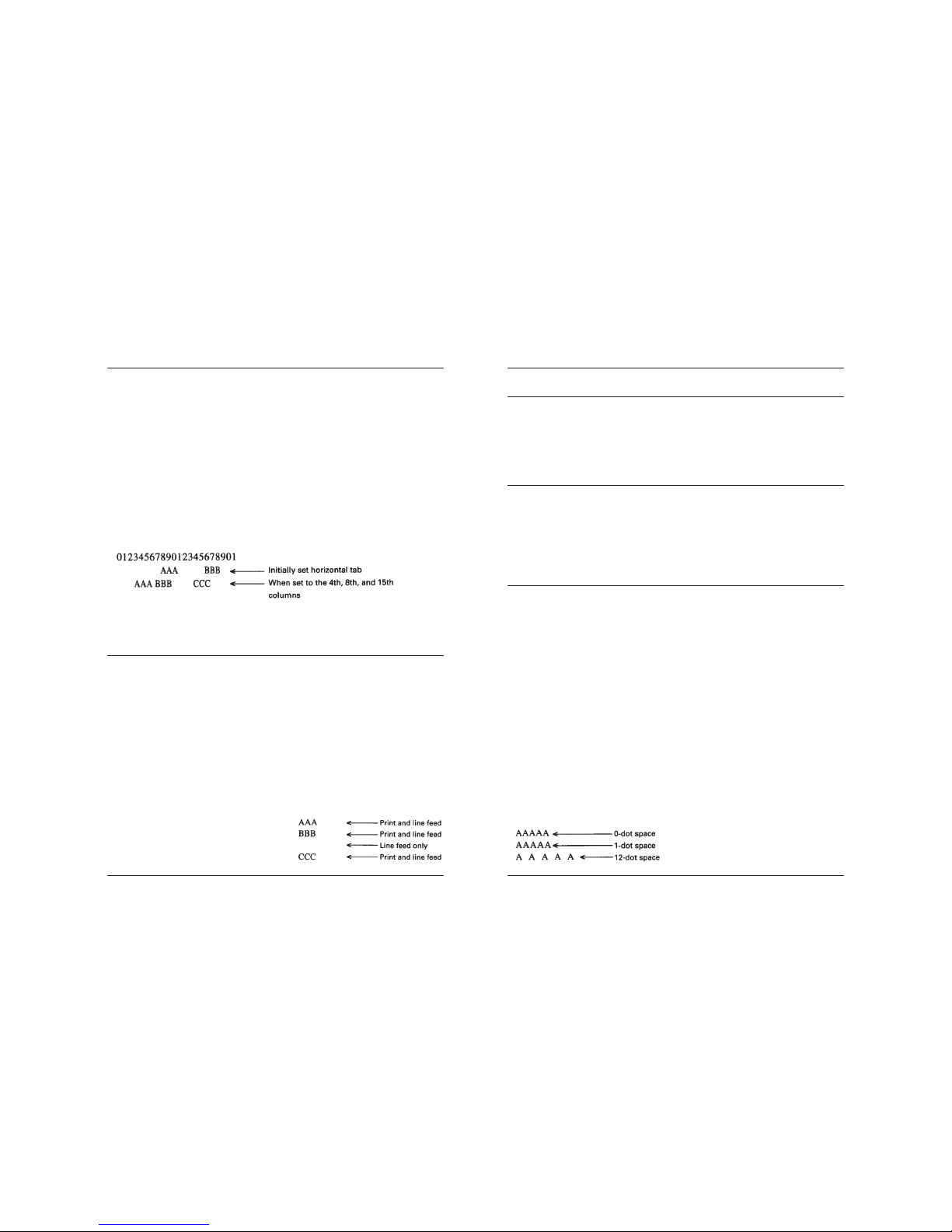
LPRINT “0123456789012345678901”;
LPRINT CHR$ (&HA);
LPRINT CHR$ (&H9) + “AAA”;
LPRINT CHR$ (&H9) + “BBB”;
LPRINT CHR$ (&HA);
LPRINT CHR$ (&H1B) + “D”;
LPRINT CHR$ (3) + CHR$ (7) + CHR$ (14) + CHR$ (0);
LPRINT CHR$ (&H9) + “AAA”;
LPRINT CHR$ (&H9) + “BBB”;
LPRINT CHR$ (&H9) + “CCC” + CHR$ (&HA);
[Print Results]
LF
Printing and Paper Feed Command
[Code] [0Ah]
[Outline] Prints data inside the input buffer and feeds lines based on
the line feed amount having been set.
The head of the line becomes the next print starting position.
[See Also] ESC 2, ESC 3
[Sample Program]
LPRINT “AAA” + CHR$ (&HA);
LPRINT “BBB” + CHR$ (&HA);
LPRINT CHR$ (&HA);
LPRINT “CCC” + CHR$ (&HA);
CR
Print Command
[Code] [0Dh]
This command is ignored.
[Print Results]
ESC RS
Sounds the beeper
[Code] [1Bh] + [1Eh]
[Outline] Sounds the beeper.
ESC SP n
Setting the right space amount of the character
[Code] [1Bh] + [20h] + n
[Range] {0 < = n <= 20 }
[Outline] The rightward space amount is set in dot unit (1/203 inch unit).
[Caution] The rightward space amount in double width mode is made
double of the set volume.
[Default] n = 0
[Sample Program]
LPRINT CHR$ (&H1B) + “ “ + CHR$ (0);
LPRINT “AAAAA” + CHR$ (&HA);
LPRINT CHR$ (&H1B) + “ “ + CHR$ (1);
LPRINT “AAAAA” + CHR$ (&HA);
LPRINT CHR$ (&H1B) + “ “ + CHR$ (12);
LPRINT “AAAAA” + CHR$ (&HA);
[Print Results]
Page 18
Line Thermal Printer DEP-50
34 35
User’s Manual
ESC $ n1 n2
Specifying the Absolute Positions
[Code] [1Bh] + [24h] + n1 + n2
[Range] {0 <= n 1 <= FFh}
{0 <= n2 <= 2}
{0 <= n1+n2*256 <= 384}
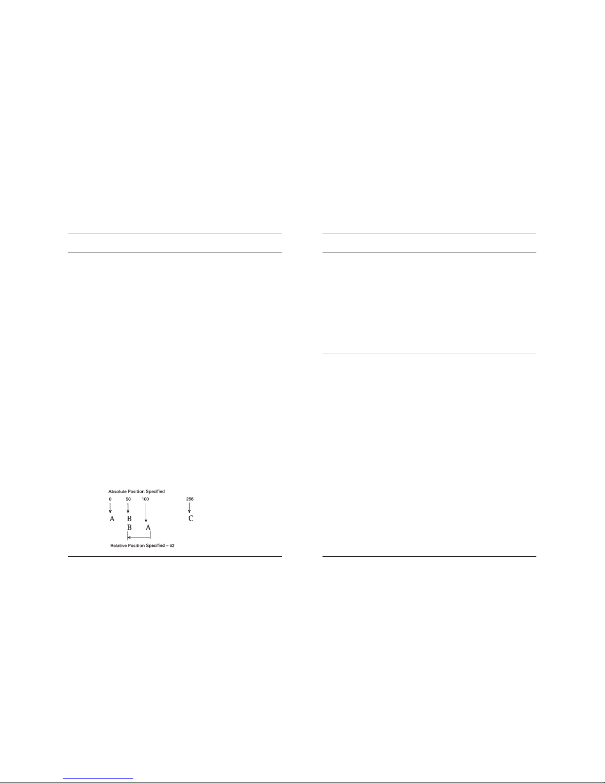
[Outline] The printing start position is specified in the number of dots
(1/203 inch unit) from the beginning of line.
• The number of dots is divided by 256, whose quotient is taken as
n2 and the residual as n1.
•Therefore, the printing start position is equal to n1 + n2 x 256 from
the beginning of line.
[Caution]
• Specifying beyond the line end is ignored.
[Default]
• The initial value is not specified.
[See Also] ESC \
[Sample Program]
LPRINT CHR$ (&H1B) + “$”;
LPRINT CHR$ (0) + CHR$ (0) + “A”;
LPRINT CHR$ (&H1B) + “$”;
LPRINT CHR$ (50) + CHR$ (0) + “B”;
LPRINT CHR$ (&H1B) + “$”;
LPRINT CHR$ (0) + CHR$ (1) + “C”;
LPRINT CHR$ (&HA);
LPRINT CHR$ (&H1B) + “$”;
LPRINT CHR$ (100) + CHR$ (0) + “A”;
LPRINT CHR$ (&H1B) + “¥”;
LPRINT CHR$ (&HC2) + CHR$ (&HFF) + “B”;
LPRINT CHR$ (&HA);
[Print Results]
ESC % n
Select/cancel user defined characters
[Code] [1Bh] + [25h] + n
• Only bit 0 of n is defined
Value 0: Selected
Value 1: Not selected
[See also] ESC &
ESC & s n1 n2 [a [d] s x a] k
ESC & m n1 n2 [ d ] k
Define user characters
There are two different types of this command selected by switch 5’s position.
If switch 5 is OFF:
[Code] [1Bh] + [26h] + s + n + m + [a1 + D1] + … + [ a
m-n+1 +Dm-n+1
]
[Range] { s = 3 }
{ 20h <= n <= FFh }
{ n <= m <= FFh }
{ 0 <= a <= 12 }
{ 0 <= D
i
<= FFh}
[Outline] Defines a group of downloaded characters where:
„s“ is the number of bytes in vertical direction – always three.
„n“ indicates the start character code and „m“ indicates the end
character code. To define only one character set n=m.
„a“ is the number of dots in horizontal direction.
„D
i
“ is the data to be defined. The number of data for each symbol is
s x a. Each symbol defines with three bytes of data in vertical
direction followed by the next three bytes that define the next
one-dot column, etc.
The downloaded font is cleared by ESC @ and ESC _ commands
and when the printer is switched off.
[Default] The default downloaded font is equal to the default character set.
However the downloaded font is not reset when the code page is
chaged, thus it remains the same as the previous code page.
Page 19
Line Thermal Printer DEP-50
36 37
User’s Manual
If switch 5 is ON:
[Code] [1Bh] + [26h] + a + n1 + n2 + D11 + … + D
(m-n+1)k
[Range] { m = 0-3 Subcommand}
{20h <= n1 <= FFh }
{n1 <= n2 <= FFh }
{k = (n2-n1+1)*48 for m=2 and k = (n2-n1+1)*16 for m=3 }
[Outline] Defines a group of user characters.
m=0: Copy internal character set A to user character set A
(Parameters n1, n2 and d are omitted)
m=1: Copy internal character set B to user character set B
(Parameters n1, n2 and d are omitted)
m=2: Define character group with ASCII codes between >=n1 and
<=n2 for character set A (12×24). Every character is 48 bytes,
two bytes for each line. Only the first nibble of the second
byte is used.
m=3: Define character group with ASCII codes between >=n1 and
<=n2 for character set B (9×16). Every character is 16 bytes.
n1 is the ASCII code of the first and n2 is the ASCII code of the last
of (n2-n1+1) consecutive symbols. To define a single symbol n1=n2.
d is the data that defines the symbols. Every Font A symbol consists
of 48 bytes while every Font B symbol consists of 16 bytes.
A Font A symbol is defined left to right, top to bottom, two bytes for
each horizontal line, as only the four most significant bits of the
second byte are used. Every bit denotes one dot. A bit set to ‘1’
means black dot. The most significant bit is the starting.
Every horizontal line of Font B symbol consists of one byte, as the
ninth point is always white. The most significant bit is the starting.
The user-defined characters are kept after printer off.
[See Also] ESC %
[Caution]
• With double height and double width being specified simultaneously,
double wide and double high characters are consisted.
• An underline is attached to the full character width, which, however,
is not attached to the part having been skipped by the horizontal tab.
Neither is it attached to 90°-right-turned characters.
• The underline width is as having been specified by <ESC - >.
(The default setting is 1 dot width)
• In case that double wide character and normal character exist in one.
[Default] n = 0
[See Also] ESC E, ESC –
[Sample Program]
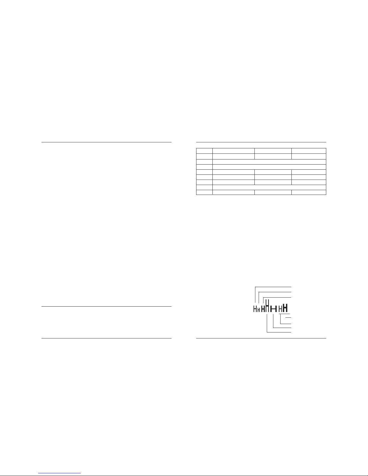
LPRINT CHR$(&H1B) + “!” + CHR$(&H00) + “H” ;
LPRINT CHR$(&H1B) + “!” + CHR$(&H01) + “H” ;
LPRINT CHR$(&H1B) + “!” + CHR$(&H08) + “H” ;
LPRINT CHR$(&H1B) + “!” + CHR$(&H10) + “H” ;
LPRINT CHR$(&H1B) + “!” + CHR$(&H20) + “H” ;
LPRINT CHR$(&H1B) + “!” + CHR$(&HB9) + “H” ;
LPRINT CHR$(&HA) ;
END
[Print Results]
ESC ! n
Collective Specifying Printing Mode
[Code] [1Bh] + [21h] + n
[Range] {0 <= n <= FFh}
[Outline] Printing mode is assigned. Each n bit indicates the following:
Bit Function Value 0 Value 1
0 Character Font Font A Font B
1 Undefined
2 Undefined
3 High-lighting Canceled Specified
4 Double height Canceled Specified
5 Double width Canceled Specified
6 Undefined
7 Underline Canceled Specified
Font A
Font B
Font A bold
Font B bold double heigth,
double widht, underline
Font A underline
Font A double widht
Font A bold double heigth
↑↑↑↑
↓↓↓
Page 20
Line Thermal Printer DEP-50
38 39
User’s Manual
ESC * m n1 n2 [ d ] k
Specifying the Bit Image Mode
[Code] [1Bh] + [2Ah] + m + n1 + n2 + D1+ … + D
k
[Range] {m= 0, 1, 32, 33 bi t image mo de (See t he table below.)}
{0 <= n1 <= FFh}
{0 <= n2 <= 3}
{0 <=d <=FFh)
{k = n1 + 256 X n2 (m = 0, 1)
{k = (n1+256 X n2) X 3} (m = 32, 33)
[Outline] According to the number of dots specified in n, n2, specify the bit
image of mode m.
• The total number of dots printed in the bit image is equal to
n1 + (256 x n2).
• When bit image data have been input in excess of dot position of
one line (384 dots), the excess data are discarded.
• d is bit image data, the bits subject to printing are taken as “1” and
those not as “0”.
• The bit image modes specified by m are shown as follows:
[Range] {m = 16, 17, 18, 20 bit image mode }
{0 <= n <= 40h}
{0 <= d <= FFh}
{k = n * 24 * 48} (m = 16)
{k = n * 24 * 48} (m = 17) { After decompression }
{k = n * h * 48} (m = 18) { After decompression }
{k = n * 24 * 48} (m = 20) { After decompression }
{0 <= a <= 24 (Used only for mode 18.)}
{f = 0 (Used only for mode 18.)}
[Outline] In these graphics modes is sent a graphics block with variable width
n*8 dots and height 24 dots for modes 16,17 and a dots for mode 18. In
mode 17 data is compressed, and the bytes count specified is before
the compression. In mode 16 the same data is without compression.
Mode 20 is similar to mode 17, but every byte is mirrored before putting
in the print buffer (bits 0 and 7, 1 and 6, 2 and 5, 3 and 4 change
places). All modes are high resolution (203 x 203 DPI).
• When bit image data have been input in excess of dot position of
one line (384 dots) , the excess data are discarded.
• d is bit image data, the bits subject to printing are taken as “1” and
those not as “0”.
[Caution]
• When the values set in m (bit image mode) are out of the above
range, the data following after n is processed as normal printing data.
• After completion of bit image printing, printer returns to normal data
processing mode.
[Compression procedure for mode 17 and 18]
A simple RLE encoding like this in PCX files is used. If two most
significant bits of the byte are set, the 6 LSB contain a repeat
counter (1-63), and the next byte contains the data to be repeated.
A single data byte with 2 MSB set must be sent as two bytes.
Vertical Direction Horizontal Direction
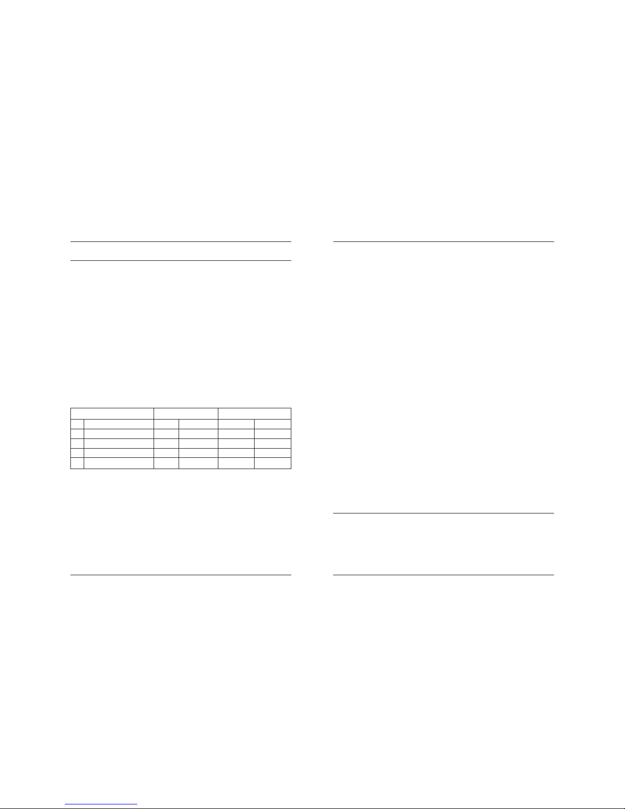
m Mode Dots Dot Density Dot Density Max. Dots
0 8-dot single density 8 67 DPI 101 DPI 192
1 8-dot double density 8 67 DPI 203 DPI 384
32 24-dot single density 24 203 DPI 101 DPI 192
33 24-dot double density 24 203 DPI 203 DPI 384
[Caution] • When the values set in m (bit image mode) are out of the above range,
the data following after n1 is processed as normal printing data.
• After completion of bit image printing, printer returns to normal data
processing mode.
The command has another variant with four new modes:
ESC * m n[ d ] k
ESC * m n a f [ d ] k
Specifying the Bit Image Mode (Sending graphics data horizontally)
[Code] [1Bh] + [2Ah] + m + n + { a + [00h] } +D1 + … +D
k
ESC – n
Specifying/ Canceling Underline
[Code] [1Bh] + [2Dh] + n
[Range] {0 < = n <= 2}
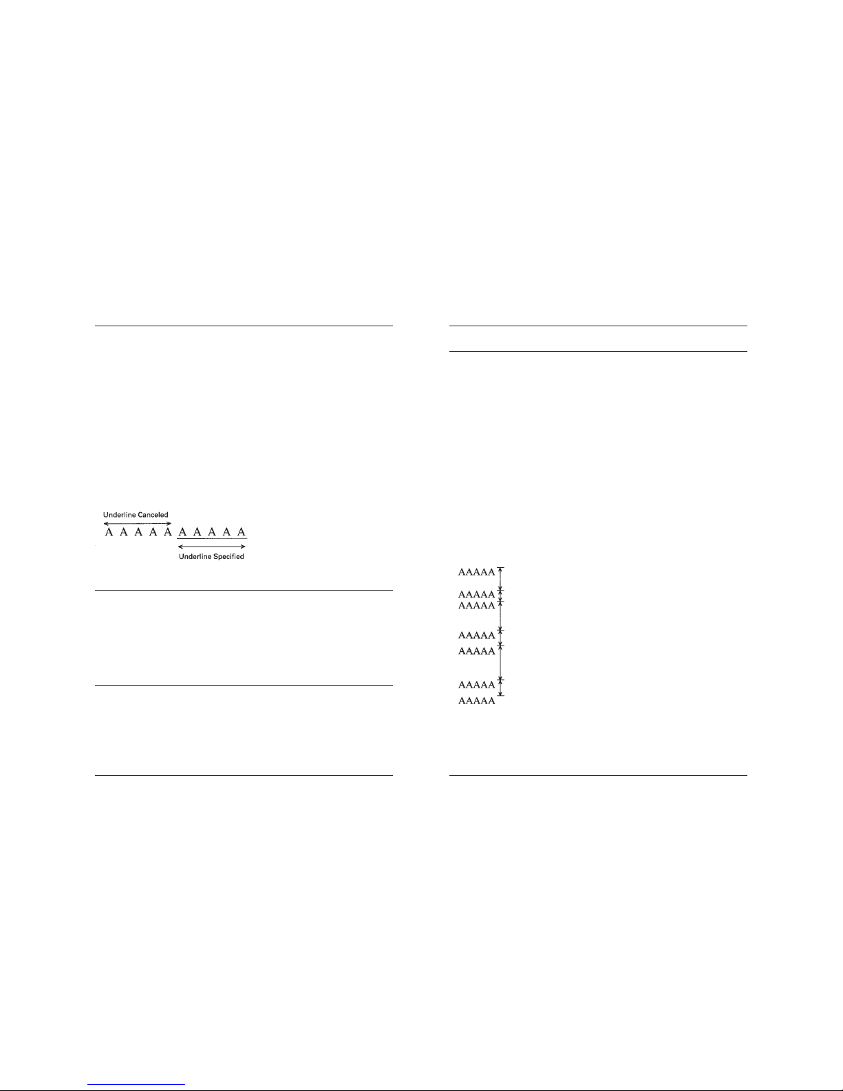
[Outline] Specifying/canceling an underline.
• Types of underlines by n value are shown below:
Page 21
Line Thermal Printer DEP-50
40 41
User’s Manual
0 Canceling an underline.
1 Specifying an underline for 1-dot width.
2 Specifying an underline for 2-dots width.
[Caution]
• An underline is attached to the full character width. It is, however,
not attached to the part having been skipped by horizontal tab
command.
• An underline is not attached to a 90
0
- right-turned characters.
[See Also] ESC !
[Sample Program]
LPRINT CHR$(&H1B) + “-” + CHR$(0);
LPRINT “AAAAA”;
LPRINT CHR$(&H1B) + “-” + CHR$(1);
LPRINT “AAAAA” + CHR$(&HA);
END
[Print Results]
ESC .
Selftest.
[Code] [1Bh] + [2Eh]
[Outline] Prints character table, character samples with different attributes
and diagnostic information.
[See also] ESC ,
ESC ,
Printing diagnostic information
[Code] [1Bh] + [2Ch]
[Outline] Printing current intensity level, temperature, code tables, communication
mode, protocol and serial port speed if a serial communication board
s installed.
[See also] ESC .
ESC 2
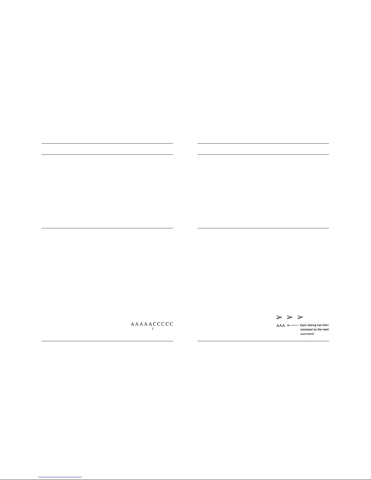
Specifying 1/6-inch line feed rate
[Code] [1Bh] + [32h]
[Outline] The line feed rate per line is specified by 1/6 inch.
[Sample Program]
LPRINT “AAAAA” + CHR$ (&HA);
LPRINT CHR$ (&H1B) + “3” + CHR$ (0);
LPRINT “AAAAA” + CHR$ (&HA);
LPRINT CHR$ (&H1B) + “3” + CHR$ (50);
LPRINT “AAAAA” + CHR$ (&HA);
LPRINT CHR$ (&H1B) + “2”;
LPRINT “AAAAA” + CHR$ (&HA);
LPRINT “AAAAA”;
LPRINT CHR$ (&H1B) + “J” + CHR$ (100);
LPRINT “AAAAA” + CHR$ (&HA);
LPRINT “AAAAA” + CHR$ (&HA);
[Print Results]
1/6-inch line feed
0/360-inch line feed
50/360-inch line feed
1/6-inch line feed
100/360-inch line feed
1/6-inch line feed
Page 22
Line Thermal Printer DEP-50
42 43
User’s Manual
ESC 3 n
Setting line feed rate of minimum pitch
[Code] [1Bh] + [33h] + n
[Range] {0 <= n <= FFh}
[Outline] The line feed rate per line is specified by n/203 inch.
[Default] The initial value is n = 34 (1/6 inch) (22H), being 4.23 mm line feed rate.
ESC > n
Set Factory Defaults
[Code] [1Bh] + [3Eh] + n
[Range] {0 <= n <= FFh}
[Outline] This command writes the current code tables, the intensity level and
the current printing speed into the flash memory. These values will
be retrieved at first power up or after a power failure.
• Value of n doesn’t matter. It is left for compatibility purpose.
[Default] • The initial values are: code tables 0 (US American CP437),
intensity level 100%, maximum printing speed.
AAAAA is not printed
ESC = n
Data Input Control
[Code] [1Bh] + [3D] + n
[Range] {0 <= n <= FFh}
[Outline] Selecting equipment in which data input from the host is effective.
• Only bit 0 is defined
Value 0: Selected
Value 1: Not selected
• When the printer has not been selected, this printer abandons all
the received data until it is selected by this command.
[Caution]
• Even when the printer has not been selected, it can become
BUSY state through printer operation.
• When the printer is deselected, this printer discards all the data
until it is selected with this command.
[Default]
• The initial value of n is “1”.
[Sample Program]
LPRINT “AAAAA”;
LPRINT CHR$ (&H1B) + “=” + CHR$ (0);
LPRINT “aaaaa” + CHR$ (&HA);
LPRINT CHR$ (&H1B) + “=” + CHR$ (1);
LPRINT “AAAAA” + CHR$ (&HA);
ESC @
Restore saved to nonvolatile RAM settings
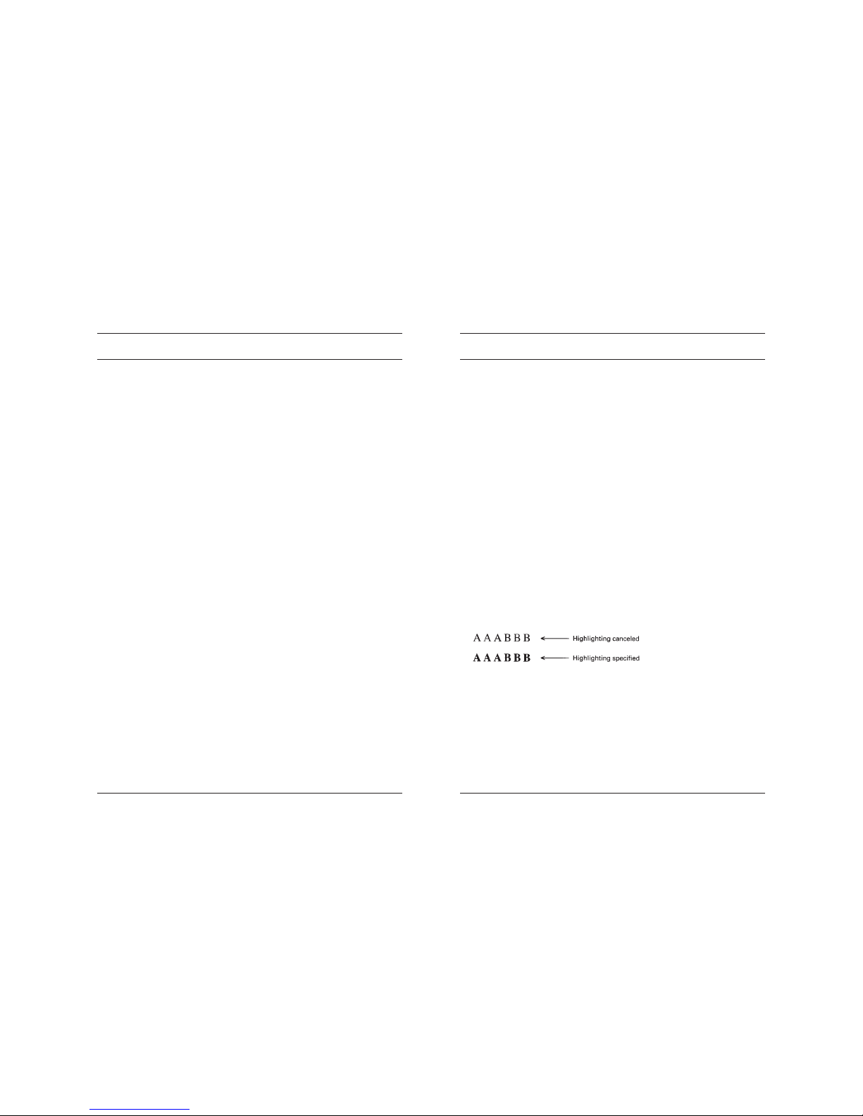
[Code] [1Bh] + [40h]
[Outline] Clears data stored in the print buffer and brings various
settings to the initial state.
[Caution]
• Data inside the internal input buffer are not cleared.
• The current code tables, print intensity and printing speed are not
reset.
• If switch 5 is OFF, the command clears the downloaded font and
bit image too.
[See also] ESC ^ and ESC _
[Sample Program]
LPRINT CHR$ (&H1B) + “ ! “ + CHR$ (&H30) ;
LPRINT CHR$ (&H1B) + “V” + CHR$ (1);
LPRINT “AAA” + CHR$ (&HA);
LPRINT CHR$ (&H1B) + “@”;
LPRINT “AAA” + CHR$ (&HA);
[Print Results]
[Print Results]
Page 23
Line Thermal Printer DEP-50
44 45
User’s Manual
ESC D [ n ] k NUL
Setting Horizontal Tab Position
[Code] [1Bh] + [44h] + n1 + … + nk + [00h]
[Range] {0 <= n <= FFh}
{0 <= k <= 20h}.
[Outline] Specifying a horizontal tab position.
• “n” indicates the no. of columns from the beginning to the
horizontal tab position. At this time, n= set position 1 is to be
specified. For example, to set the position at 9th column, n=8 is to
e specified.
• k denotes the number of horizontal tab positions you want to set.
• The tab position is set at position where it is “character width x n”
from the line beginning. The character width, at this time, includes
the rightward space amount. In double wide characters, it is made
double of the ordinary case.
• Tab positions can be specified are maximum 32.
Specifying exceeding this is ignored.
• <n> k, which denotes a setting position, is input in the increasing
order and ends at <00>H.
• ESC D NUL clears all the set tab positions. Following clearing,
horizontal tab command is ignored.
[Caution] When the data, <n> k, is equal to or smaller than its preceding data,
<n>k-1, it is assumed that tab setting is finished. If this is the case, the
next data onward will be processed as normal data. When the data,
<n> k, exceeds a 1-line print area, set the horizontal tab position,
assuming “Set digit position = Maximum print digits + 1.” The horizontal
tab position does not change even if the character width is altered
after setting the horizontal tab position.
[Default]
• Initial value is specified for each eight characters
(9 th .17 th .25 th column).
[See Also] HT
ESC E n
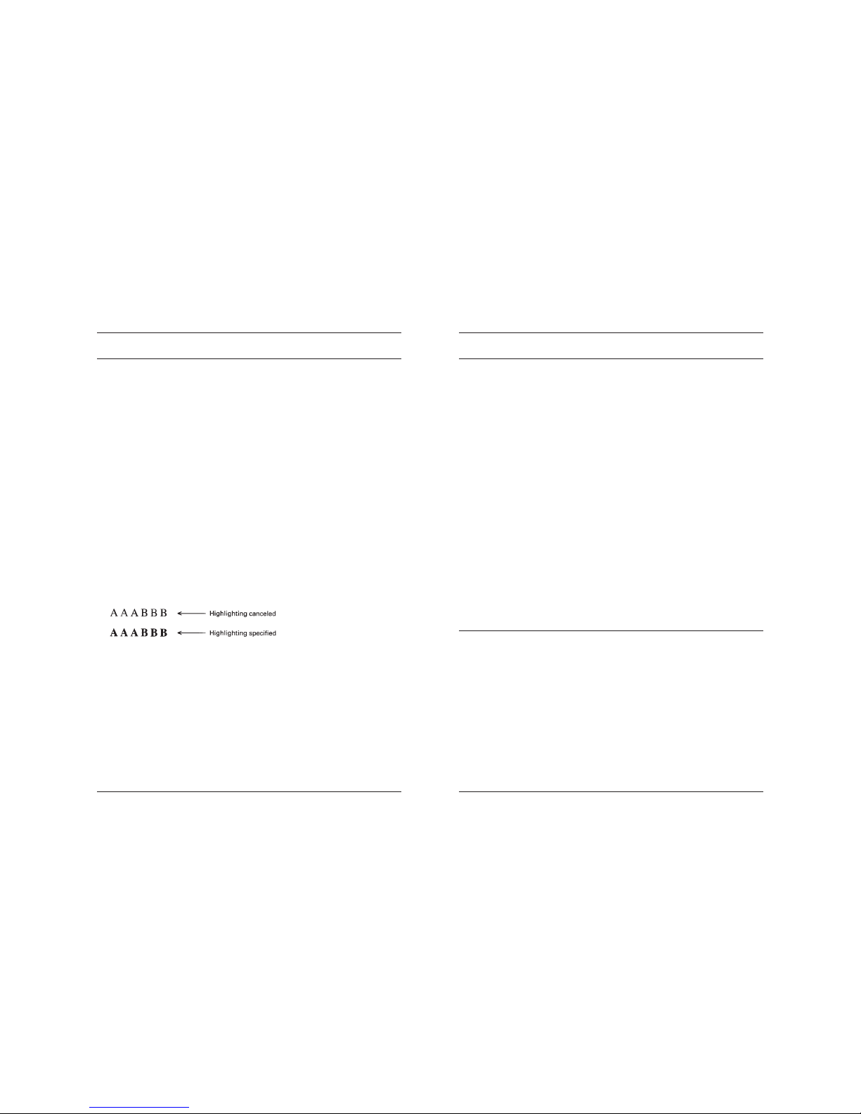
Specifying/canceling highlighting
[Code] [1Bh] + [45h] + n
[Range] {0 <= n <= FFh}
[Outline] Specifying/canceling the highlighting characters.
• “n” is valid only for the lowest bit (n0).
• Control by the lowest bit (n0) is shown as follows:
0 Canceling highlighting.
1 Specifying highlighting.
• This is effective to all characters of font A.
• Characters of font B are not highlighted.
• Dot configuration of a highlighted character includes one extra dot
added at its side.
[Caution]
• The print result of Double printing and highlight character printing is
completely same.
[See Also] ESC !
[Sample Program]
LPRINT CHR$ (&H1B) + “E” + CHR$ (0);
LPRINT “AAABBB” + CHR$ (&HA);
LPRINT CHR$ (&H1B) + “E” + CHR$ (1);
LPRINT “AAABBB” + CHR$ (&HA);
[Print Results]
Page 24
Line Thermal Printer DEP-50
46 47
User’s Manual
ESC G n
Specifying/canceling Double Printing (ESC G n)
[Code] [1Bh] + [47h] + n
[Range] {0 <= n <= FFh}
[Outline] Specifying/canceling the double printing.
• “n” is valid only for the lowest bit (n0).
• Control by n is shown as follows.
0 Canceling double printing.
1 Specifying double printing.
• This is effective to all characters of font A.
• Characters of font B are not highlighted.
[Caution]
• The print result of Double printing and highlight character
printing is completely same.
[See Also] ESC E
[Sample Program]
LPRINT CHR$ (&H1B) + “G” + CHR$ (0);
LPRINT “AAABBB” + CHR$ (&HA);
LPRINT CHR$ (&H1B) + “G” + CHR$ (1);
LPRINT “AAABBB” + CHR$ (&HA);
[Print Results]
ESC I n
Specifying/cancelling italic printing (ESC I n)
[Code] [1Bh] + [49h] + n
[Range] {0 <= n <= FFh}
[Outline] Specifying/canceling the double printing.
• “n” is valid only for the lowest bit (n0).
• Control by n is shown as follows.
0 Canceling italic printing.
1 Specifying italic printing.
[Sample Program]
LPRINT CHR$(&H1B) + “I” + CHR$(0);
LPRINT “BBBBB”;
LPRINT CHR$(&H1B) + “I” + CHR$(1);
LPRINT “BBBBB”;
[Print Results]
BBBBBBBBBB
ESC J n
Printing and feeding paper n/203 inch
[Code] [1Bh] + [4Ah] + n
[Range] {0 <= n <= FFh}
[Outline] Prints data inside the print buffer and feeds paper by
n/203 inch. Since an actual mechanical pitch is 1/203 inch,
it is internally converted approximate to the value specified
with this command.
• Specified volume does not remain.
• The beginning of the line is to be considered as the next printing
start position.
• Initial value is not defined.
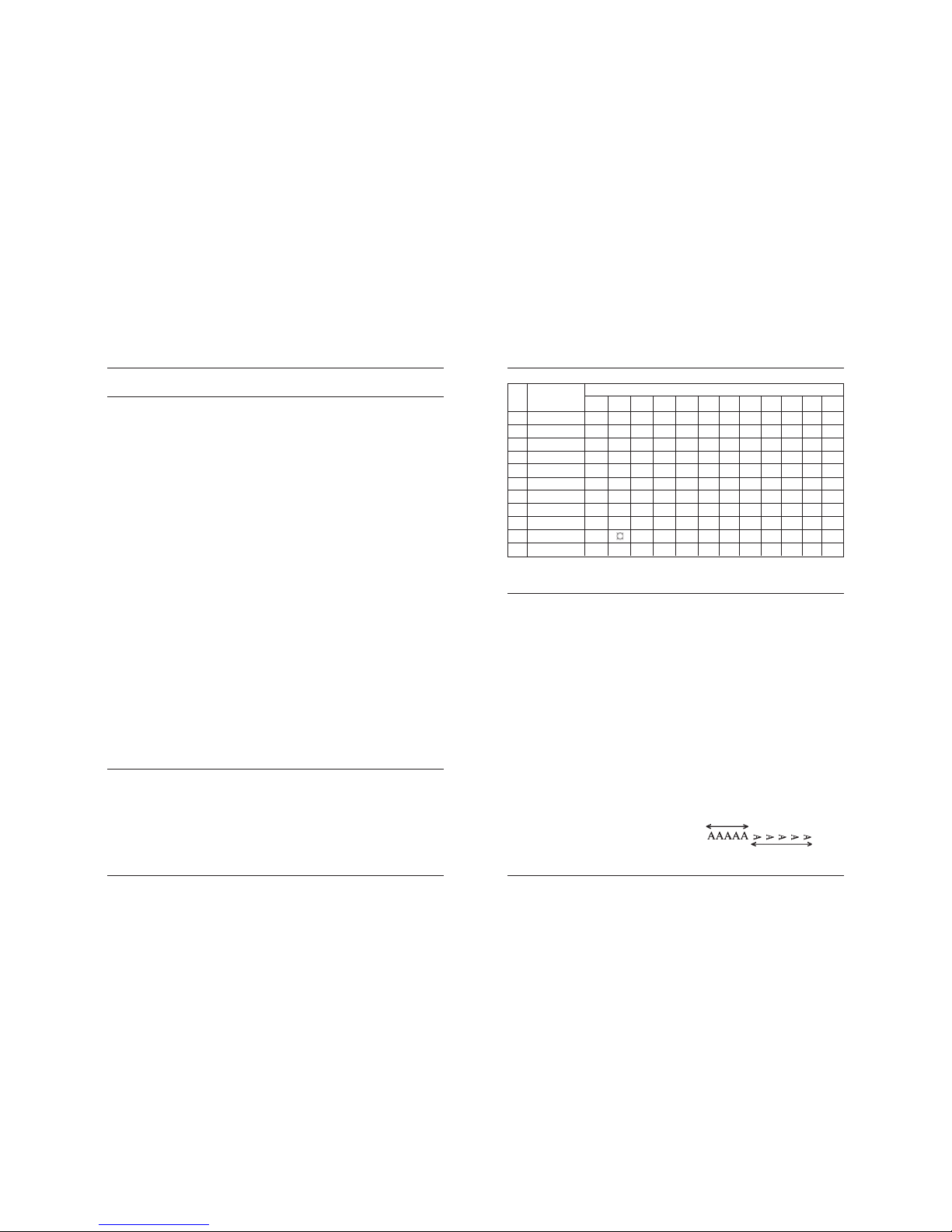
Page 25
Line Thermal Printer DEP-50
48 49
User’s Manual
ESC M n
Specifying/canceling highlighting
[Code] [1Bh] + [4Dh] + n
[Range] {0 <= n <= FFh}
[Outline] Selects character font.
• “n” is valid only for the lowest bit (n0).
• Control by the lowest bit (n0) is shown as follows:
0 Selection of font A (12x24).
1 Selection of font B (9x16).
[Caution] ESC ! can also select fonts, but the setting made by the command
processed last is valid.
[See also] ESC !
[Sample Program]
LPRINT CHR$(&H1B) + “M” + CHR$(0);
LPRINT “AAAAA”;
LPRINT CHR$(&H1B) + “M” + CHR$(1);
LPRINT “AAAAA”;
[Print Results]
AAAAAAAAAA
n Country
Character Set
23h 24h 40h 5Bh 5Ch 5Dh 5Eh 60h 7Bh 7Ch 7Dh 7Eh
0 U.S.A. # $ @ [ \ ] ^ ‘ { | } ~
1 France # $ à º ¢ § ^ ‘ é ù è ¨
2 Germany # $ § Ä Ö Ü ^ ‘ ä ö ü ß
3 U.K. £ $ @ [ \ ] ^ ‘ { | } ~
4 Denmark I # $ @ Æ Ø Å ^ ‘ æ ø å ~
5 Sweden # $ É Ä Ö Å Ü é ä ö å ü
6 Italy # $ @ º \ é ^ ù à ò è ì
7 Spain I P t $ @ ¡ Ñ ¿ ^ ‘ ¨ ñ } ~
8 Japan # $ @ [ ¥ ] ^ ‘ { | } ~
9 Norway # É Æ Ø Å Ü é æ ø å ü
10 Denmark II # $ É Æ Ø Å Ü é æ ø å ü
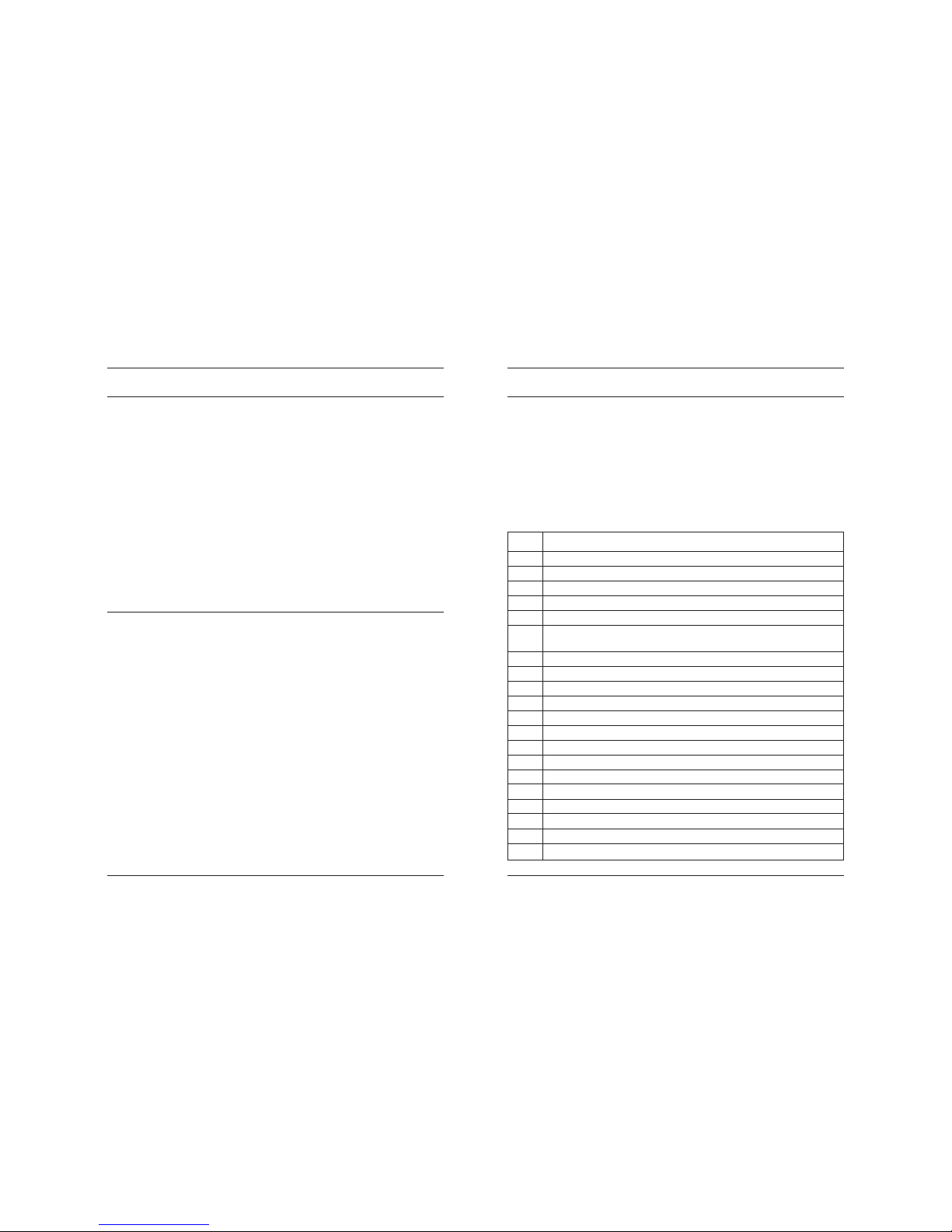
ESC R n
Selecting international character set
[Code] [1Bh] + [52h] + n
[Range] {0 <= n <= 10}
[Outline] Depending on the value of „n“, one of the following character sets
is selected:
ESC V n
Specifying/Canceling 90º -right- turned Characters
[Code] [1Bh] + [56h] + n
[Range] {0 < = n <= 1} .
[Outline] Specifying/canceling characters 90º -right- turned character.
• “n” means the followings.
0 Canceling 90º -right- turned Characters
1 Specifying 90º -right- turned Characters
[Caution]
• No underlines are attached to 90º -right- turned characters .
[Default]
• The initial value of n is “0”.
[Sample Program]
LPRINT CHR$ (&H1B) + “V” + CHR$ (0);
LPRINT “AAAAA”;
LPRINT CHR$ (&H1B) + “V” + CHR$ (1);
LPRINT “AAAAA” + CHR$ (&HA);
[Print Results]
90o Rotation Specified
90
o
Rotation Canceled
Page 26
Line Thermal Printer DEP-50
50 51
User’s Manual
ESC X n
Select maximum printing speed
[Code] [1Bh] + [58h] + n
[Range] {0 <= n <= 3}
{‘0’ <= n <= ‘3’}
[Outline] Selects the maximum printing speed according to the value of ‘n’:
0 or ‘0’ about 50 mm/s
1 or ‘1’ about 42 mm/s
2 or ‘2’ about 33 mm/s
3 or ‘3’ about 25 mm/s
These values are approximate. The real maximum speed depends
on the print intensity and the printing head’s temperature.
[Default] The default value is 0 – maximal printing speed.
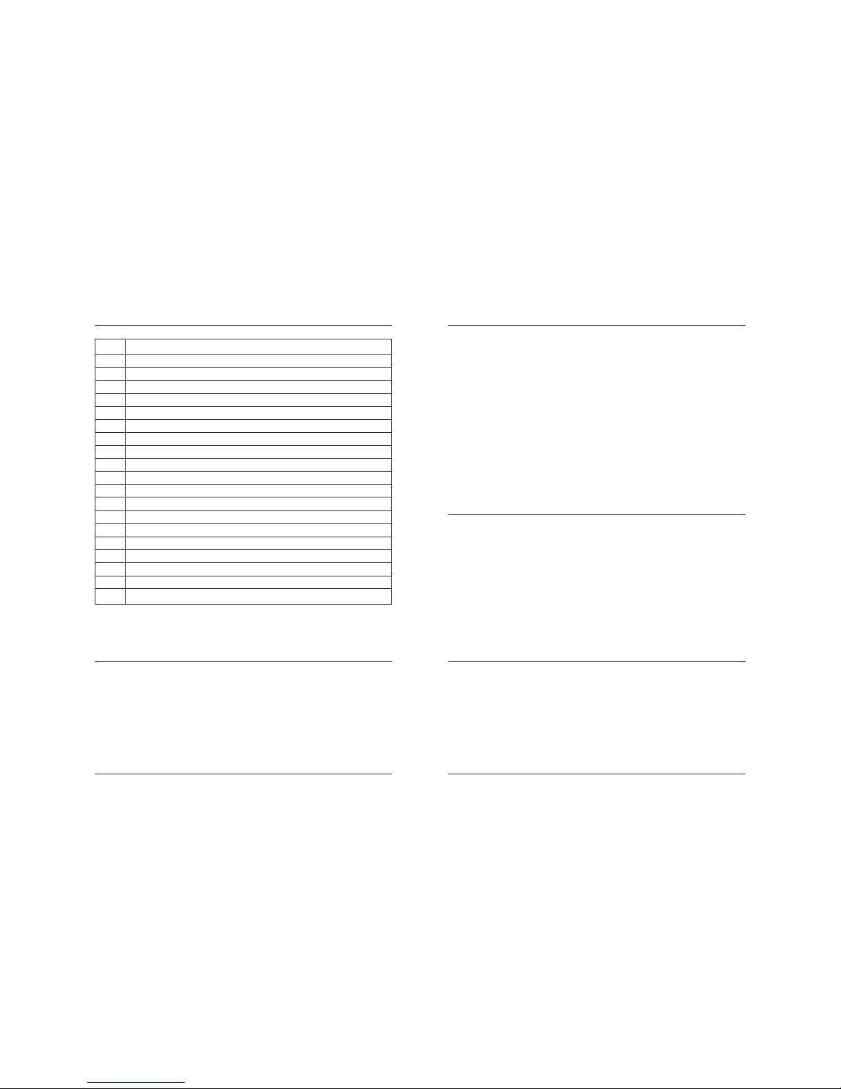
ESC Z
Transmits identification string.
[Code] [1Bh] + [5Ah]
[Outline] The printer transmits 32 bytes of information with the
following structure:
1 – 22: Printer name complemented with space up to 22 symbols.
23 – 25: Firmware version – 3 digits (in ASCII format).
26 – 26: Language version – 2 letters.
28 – 32: 5 bytes flags. Each bit describes a printer feature, as ‘1’
means that the feature is present, while ‘0’ means its
absence. Bits are described as follows:
ESC Y n
Selecting the intensity level
[Code] [1Bh] + [59h] + n
[Range] {0 <= n <= 5}
[Outline] Set the intensity level.
• “n” means the followings.
0 Set intensity 70 %
1 Set intensity 80 %
2 Set intensity 90 %
3 Set intensity 100 %
4 Set intensity 120 %
5 Set intensity 150 %
[Caution]
• Higher intensities can cause a lower speed.
[Default]
• The initial value of n is 3.
[Sample Program]
LPRINT CHR$ (&H1B) + “Y” + CHR$ (0);
LPRINT “AAAAA”;
LPRINT CHR$ (&H1B) + “Y” + CHR$ (5);
LPRINT “AAAAA” + CHR$ (&HA);
Bit Meaning
28.0 Supports IrDA mode
28.1 Supports magnetic card reader
28.2 Supports simultaneous reading of three tracks from a magnetic card
28.3 ASCII codes above 127 contain Katakana symbols
28.4 Supports JIS and Shift-JIS symbols
28.5 Prints when ESC . and ESC T, and transmits when ESC ‘
the temperature in º Fahrenheit
28.6 Not Used
28.7 Reserved – always 1
29.0 Suppor ts downloadable fonts and firmware
29.1 Korean support
29.2 Black mark support
29.3 Barcode reader support
29.4 USB A installed
29.5 USB B installed
29.6 Not Used
29.7 Reserved – always 1
30.0 Not Used
30.1 Not Used
30.2 Not Used
30.3 Not Used
Page 27
Line Thermal Printer DEP-50
52 53
User’s Manual
ESC \ n1 n2
Specifying the Relative Positions
[Code] [1Bh] + [5Ch] + n1 + n2
[Range] {0 <= n 1 <= FFh}
{0 <= n2 <= FFh}
[Outline] The printing start position is specified in the number of
dots(1/203 inch unit) from the current position.
• Rightward direction is taken as plus and leftward direction as minus.
30.4 Not Used
30.5 Not Used
30.6 Not Used
30.7 Reserved – always 1
31.0 Not Used
31.1 Not Used
31.2 Not Used
31.3 Not Used
31.4 Not Used
31.5 Not Used
31.6 Not Used
31.7 Reserved – always 1
32.0 Not Used
32.1 Not Used
32.2 Not Used
32.3 Not Used
32.4 Not Used
32.5 Not Used
32.6 Not Used
32.7 Reserved – always 1
• To specify N dot in minus (left) direction, use a complement of N for
assignment.
– N dots = 65536 – N
• The number of dots is divided by 256, whose quotient is taken as n2
and the residual as n1.
• There are 384 dots per line (positions from 0 to 383).
[Caution]
• Specifying exceeding the beginning of the line or the end of the line
ignored.
[Default]
• The initial value is not specified.
[See Also] ESC $
ESC _
Restore factory defaults and save them to nonvolatile RAM
[Code] [1Bh] + [5Fh]
[Outline] Select font A, no bold, no underline, etc. Restore tab defaults.
The parameters are read from the flash memory.
Downloaded font and downloaded bit image are cleared.
Copy internal fonts A and B to user fonts. DIP switches are read again.
Data in the input buffer is not cleared.
[See also] ESC @
ESC ‘
Transmits the current power supply voltage and the print head temperature.
[Code] <1B>H<60>H
[Outline] The printer transmits two bytes data. First byte is the power
supply voltage given as 0.1 mV plus 20h. the second byte is
the print head temperature, in degrees Celsius, plus 20h.
[Example] If the battery voltage is 6.4 V, and the print head temperature is 33°C,
the printer will transmit <60h><41h>, which is <40h+20h><21h+20h>
or <64+32><33+32>.
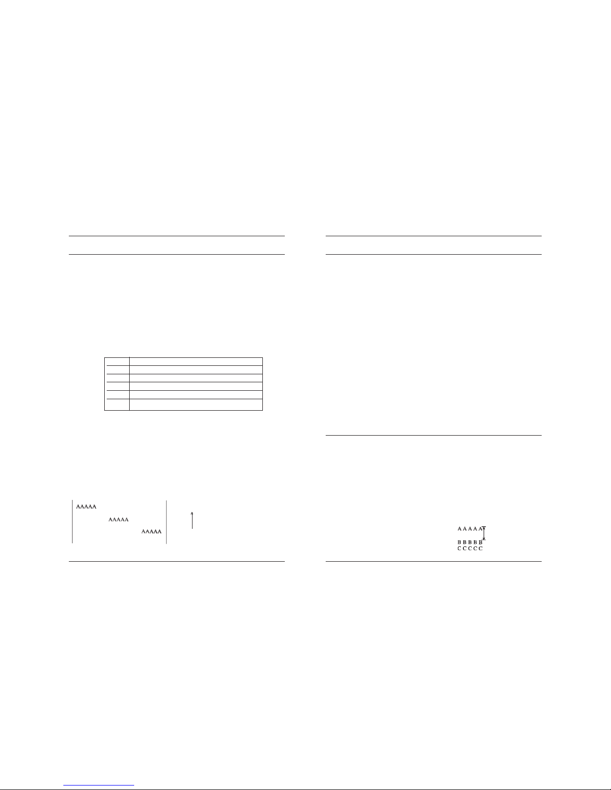
Page 28
Line Thermal Printer DEP-50
54 55
User’s Manual
ESC a n
Aligning the characters
[Code] [1Bh] + [61h] + n
[Range] {0 <= n <= 2}
{4 <= n <=6 }
[Outline] This command is extended and has the following format:
All the printed text data, the barcode or the raster bit image (GS v0)
within one line are aligned in the specified position. If used before
printing a barcode with this command can be specified vertical
direction for printing the barcode.
• Depending on n value, positional alignment is carried out as in the
table below:
Left-justified Centred Right-justified
Paper Feed Direction
0 Left end alignment
1 Centering
2 Right end alignment
4 Left end aligned vertical barcode
5 Centered vertical barcode
6 Right end aligned vertical barcode
[Default]
• The initial value of n is “0”.
[Sample Program]
LPRINT CHR$ (&H1B) + “a” + CHR$ (0);
LPRINT “AAAAA” + CHR$ (&HA);
LPRINT CHR$ (&H1B) + “a” + CHR$ (1);
LPRINT “AAAAA” + CHR$ (&HA);
LPRINT CHR$ (&H1B) + “a” + CHR$ (2);
LPRINT “AAAAA” + CHR$ (&HA);
[Print Results]
ESC c5 n
Enabling/Disabling Panel Switches
[Code] [1Bh] + [63h] + [35h] + n
[Range] {0 <= n <= FFh}
[Outline] Selecting the LF switch valid/invalid.
• “n” is valid only in the lowest bit (n0).
• “n” bit means the followings.
0 LFSW valid.
1 LFSW invalid.
[Caution] When the panel switch is disabled with this command, the LF switch
is disabled. Therefore, the paper cannot be fed by op erating the LF
switch.
[Default]
• The initial value of n is “0”.
[Sample Program]
LPRINT CHR$ (&H1B) + “c5” + CHR$ (0); ¼¼
When enabling the LF switch
LPRINT CHR$ (&H1B) + “c5” + CHR$ (1); ¼¼
When disabling the LF switch
ESC d n
Printing and Feeding the paper by n lines
[Code] [1Bh] + [64h] + n
[Range] {0 < = n <= FFh}
[Outline] Prints data inside the buffer and feeds paper by n lines.
• Specified line does not remain.
• The beginning of the line is to be considered as the next printing
start position.
[Default]
• The initial value is not defined.
[Sample Program]
LPRINT “AAAAA”
LPRINT CHR$ (&H1B) + “d” + CHR$ (2);
LPRINT “AAAAA” + CHR$ (&HA);
[Print Results]
2/6-inch line feed
Page 29
Line Thermal Printer DEP-50
56 57
User’s Manual
ESC t
Selecting the character code table
[Code] [1Bh] + [74h] + n
[Range] { 0 < = n <= 19 }
[Outline] Selects the code table for ASCII codes 80h-FFh.
In the international version of the printer one of the following
supported code tables is selected according to the value of n:
ESC i
Cutting the paper
[Code] [1Bh] + [69h]
[Outline] Performs a paper feed, so the last printed line remains after the cover’s
cutting edge.
This command is valid only at the beginning of the line.
ESC p
Generating a drawer-kick pulse
[Code] [1Bh] + [70h] + m + n1 + n2
[Range] { 0 < = m <= 255 }
{ 0 <= n1 <= 255 }
{ 0 <= n2 <= 255 }
[Outline] The value of m is ignored.
The printer generates a 2*n1 milliseconds long pulse and
2*n2 milliseconds long rest after the pulse. n2 must be at
least four times greater than n1 or the command will be dis
carded.
[Sample Program]
LPRINT CHR$(&H1B) + “p”;
LPRINT CHR$(0);
LPRINT CHR$(5); Sets ON time to 10ms
LPRINT CHR$(50); Sets OFF time to 100ms
END
ESC m
Cutting the paper
[Code] [1Bh] + [6Dh]
[Outline] The command is exactly the same as ESC i.
n Code Table
0 USA (CP437)
1 Litva
2 West Europe Latin I (CP850)
3 Brasil (CP860)
4 Poland
5 Bulgarian (CP856)
6 Central Europe Latin II (CP852)
7 Russian (CP866)
8 Turkish (CP857)
9 Windows English Latin I (CP1252)
10 Baltic (CP775)
11 Latvia
12 Greek (CP737)
13 Hebrew (CP862)
14 Windows Central European Latin II (CP1250)
15 Windows Cyrilic (CP1251)
16 Windows Greek (CP1253)
17 Windows Turkish (CP1254)
18 Windows Hebrew (CP1255)
19 Windows Baltic (CP1257)
In the Chinese version of the printer one of the following supported
code tables is selected according to the value of n:
Page 30
Line Thermal Printer DEP-50
58 59
User’s Manual
ESC x n
Reversing the print direction
[Code] [1Bh] + [78h] + n
[Outline] This command changes the characters’ print direction from left to
right to right to left. The character itself is not mirrored horizontally.
The command is intended for languages that use right to left
scripting, like Hebrew and Arabic.
Only the lowest bit of “n” is valid with the following meaning:
0 – left to right printing
1 – right to left printing
[Caution] The command changes only the print direction of the characters - all
graphics and bar codes are unaffected.
This command is ignored in the Chinese version of the printer.
The command reverses all print attributes of the line and the characters,
though the characters themselves are not mirrored horizontally.
Though the command allows mixing reversed and non-reversed
characters in one line the print results could be unsatisfactory and
unreliable.
[Default] The default value is 0 – left to right printing.
[Exsample]
n Code Table
0 USA (CP437)
1 Chinese GB2312
[Caution] In the international version of the printer when the code page is set
by the DIP switches the command is disabled and a code page
other than this one cannot be set.
In the Chinese version of the printer the code table can be changed
regardless of the DIP switch setting.
If the code page is set by the DIP switches the command ESC > wil
store this code page into the flash for further use.
[Default] The default value is 0 – USA CP437 code page.
ESC v
Transmitting the printer status
[Code] [1Bh] + [76h]
[Outline] Current printer status is transmitted..
Status sent out consists of 1 byte whose content is as in the
table below.
Bit Function Value 0 Value 1
0 Not defined
1 Not defined
2 Paper end With paper Without paper
3 Head temperature Normal Overheated
4 Not defined
5 Not defined
6 Not defined
7 Not defined
[Sample Program]
OPEN “COM1:N81NN” AS #1 ;
PRINT #1, CHR$ (&H1B) ; “v” ;
A$ = INPUT$ (1, #1) ;
CLOSE #1
END
ESC { n
Specifying/Canceling the Inverted Characters
[Code] [1Bh] + [7Bh] + n
[Range] {0 <= n <= FFh}
[Outline] Specifying/canceling inverted characters.
• “n” is valid only for the lowest bit (n0).
• Bit n (n0) means the followings.
0 Canceling inverted characters.
1 Specifying inverted characters.
[Caution]
• Inverted printing means printing the line at 180º turned.
• Valid is the last value specified in a line.
[Default]
• The initial value of n is “0”.
Page 31
Line Thermal Printer DEP-50
60 61
User’s Manual
[Sample Program]
LPRINT CHR$ (&H1B) + “{“ + CHR$ (0);
LPRINT “AAAAA” + CHR$ (&HA);
LPRINT “BBBBB” + CHR$ (&HA);
LPRINT CHR$ (&H1B) + “{“ + CHR$ (1);
LPRINT “AAAAA” + CHR$ (&HA);
LPRINT “BBBBB” + CHR$ (&HA);
[Print Results]
Inversion Canceled
Inversion Specificed
Paper Feed Direction
GS (A pL pH n m
Printing a self-test
[Code] [1Dh] + [28h] + [41h] + pL + pH + n + m
[Range] { 0 < = pL <= 255 }
{ 0 <= pH <= 255}
{ 0 <= n <= 255 }
{ 2 <= m <= 3 }
[Outline] This command is intended for compatibility purposes. A
“short” or “long” test is printed depending on the value of m.
m = 2 – printing a “long” test (ESC .)
m = 3 – printing diagnostic information (“short” test) (ESC ,)
GS B n
Specifying/canceling the black/white inverted printing
[Code] [1Dh] + [62h] + n
[Range] { 0 <= n <= 255 }
[Outline] According to the least significant bit of n (n0) the following modes
are possible:
n0 = 0 – Black/white inverted printing is canceled
n0 = 1 – Black/white inverted printing is specified
The space skipped by tab command or by positioning commands
(ESC $, ESC \) is not affected.
Both built-in and downloaded character sets are inverted by this
command.
The black/white inversion works on the right space defined by ESC SP
command.
[Default] The initial value is n=0
[Sample Program]
LPRINT CHR$(&H1D) + “B” + CHR$(0);
LPRINT “AAAAA”;
LPRINT CHR$(&H1D) + “B” + CHR$(1);
LPRINT “AAAAA”;
[Print Results]
AAAAAAAAAA
Page 32

Line Thermal Printer DEP-50
62 63
User’s Manual
GS L n1 n2
Setting the left margin
[Code] [1Dh] + [4Ch] + n1 + n2
[Range] {0 <= n 1 <= FFh}
{0 <= n2 <= FFh}
{n1+256*n2 < 384}
[Outline] Sets the position in dots (1/203 inches) from which each
line starts. This command works only if entered at the
beginning of the line. The start position is equal to
n1+256*n2 dots from the left end of the printable area.
[Caution] If a value that exceeds the length of the print area is set the
left margin is set to 0.
[Default] Default value is 0.
(1) GS V m
(2) GS V m n
Cutting the paper
[Code] (1) [1Dh] + [56h] + m
(2) [1Dh] + [56h] + m + n
[Range] (1) {m=1, m=49}
(2) {m=66}
{0 <= n <= 255}
[Outline] Depending on the value of m one of the following actions is
performed:
- if m=1 or m=49 (‘1’) a paper feed, so the last printed line remains
after the cover’s cutting edge is performed.
- if m=66 (‘B’) the paper is fed by n/8 mm.
In both cases the paper is first fed to the cut position so the
last printed line remains after the cutter’s edge. This means
at in case (2) the paper is fed by “cut position + n/8”
millimeters total.
(1) GS k m [ d ] k NUL
(2) GS k m n [ d ] k
(3) GS k m a [ d ] k NUL
(4) GS k m a xL xH [ d ] k
Printing the barcode
[Code] (1) [1Dh] + [6Bh] + m + Di + [00h]
(2) [1Dh] + [6Bh] + m + n + D
i
(3) [1Dh] + [6Bh] + m + a + Di + [00h]
(4) [1Dh] + [6Bh] + m + a + xL + xH + D
i
[Range] (1) {0 <= m <= 6}
(2) {65 <= m <= 73}
(3) {m=9; a=0,1}
(4) {m=74; 256*xH+xL<=3000; a=0,1}
[Outline] Specifying a type of barcode and printing barcodes.
•The beginning of line is considered as the next printing start position.
• Depending on the value of m, the following barcode can be selected.
d indicates a barcode data to be printed and k indicates the number
of character to be printed.
n indicates indicates number of characters when 65 <= m <= 73.
a is a setting for PDF-417 barcode. Setting a=0 will make the printer
to automatically choose PDF-417 compression modes, while a=1
will force byte compression mode.
xL and xH indicates the number of bytes for PDF-417 barcode
when m=74. The number of bytes is equal to 256*xH+xL.
m determines barcode type and it is one of the following:
Page 33
Line Thermal Printer DEP-50
64 65
User’s Manual
m (1) Barcode type Length Range of ‘d’
0 UPC-A 11 48 <= Di <= 57
1 UPC-E 11 48 <= Di <= 57
2 EAN13 (JAN13) 12 48 <= Di <= 57
3 EAN 8 (JAN8) 7 48 <= Di <= 57
4 CODE 39 - 48 <= Di <= 57, 65 <= Di <= 90,
32, 36, 37, 43, 45, 46, 47
5 ITF - 48 <= Di <= 57
6 CODABAR (NW-7) - 48 <= Di <= 57, 65 <= Di <= 68,
36, 43, 45, 46, 47, 58
7 CODE 93 - 1 <= Di <= 127
8 CODE 128 - 1 <= Di <= 127
9 PDF-417 - 1 <= Di <= 255
[DESCRIPTION OF BAR CODES]
UPC-A This bar code, consisting of numerals only, has a fixed length of 12
column; a 11-columns number entered from the host or application
software plus a check column(12th column) automatically calculaed
inside the printer. If the 12th-column numeral is sent from the host,
the entire bar code will be printed as it is.
UPC-E This bar code, consisting of numerals only, has a fixed length of 8
column; the first number system character is “0” stationary. A 12
column numeral entered from the host or application software is
compressed to 8 columns with a check column and printed. The
12th-column check column is automatically calculated inside the
printer and sent from the host, the entire bar code will be printed,
compressed to 8 columns.
JAN-13 This bar code, consisting of numerals only, has a fixed length of
(EAN) 13 column; a 12-column number entered from the host or application
software plus a check column(13th column) automat cally
calculated inside the printer. If the 13th-column numeral is sent from
he host, the entire bar code will be printed as it is.
JAN-8 This bar code, consisting of numerals only, has a fixed length of 8
(EAN) column; a 7-column number entered from the host or application
software plus a check column(8th column) automatically calculated
inside the printer. If the 8th-column numeral is sent from the host,
the entire bar code will be printed as it is.
CODE39 This bar code, consisting of uppercase alphabets and numerals,
has a variable length of column. A start/stop code “*” is automatcally
added by the printer. Available characters include a space and “$,
%, +, -, · , /, 0, 1, 2, 3, 4, 5, 6, 7, 8, 9,” and uppercase alphabets.
ITF This bar code, consisting of numerals only, has a variable length of
even column. If an odd-column code is tranferred, nothing will be printed.
CODABAR This bar code, consisting of alpha numerals, has a variable
(NW-7) length of column. Available characters include “0, 1, 2, 3, 4, 5, 6, 7,
8, 9, A, B, C, D, $, +, -,., /, :.” A start/stop code is required; any one
of A, B, C, and D is used.
CODE 93 This barcode, consisting of alphanumeric and control characters, has
a variable length of columns. HRI characters for control characters
(00H - 1FH, and 7FH) are each printed as a combination of a “^”
character and an alphabetic character.
M (2) Barcode type Length Range of ‘d’
65 UPC-A 11 48 <= Di <= 57
66 UPC-E 11 48 <= Di <= 57
67 EAN13 (JAN13) 12 48 <= Di <= 57
68 EAN 8 (JAN8) 7 48 <= Di <= 57
69 CODE 39 - 48 <= Di <= 57, 65 <= Di <= 90,
32, 36, 37, 43, 45, 46, 47
70 ITF - 48 <= Di <= 57
71 CODABAR (NW-7) - 48 <= Di <= 57, 65 <= Di <= 68,
36, 43, 45, 46, 47, 58
72 CODE 93 - 0 <= Di <= 127
73 CODE 128 - 0 <= Di <= 127
74 PDF-417 - 0 <= Di <= 255
[Caution] • When data being held in the print buffer, this command is ignored.
• Regardless of the specified feed pitch, this command feeds the
paper that is required to print a barcode.
• If the character code d cannot be printed in the respective barcode
system, the barcode so far will be printed, processing the
subsequent data as normal data.
• When a barcode whose number of characters to be printed is fixed
has been selected, the number of characters k have to be always
made equal to the number of characters to be printed. (The barcode
is not printed when not matching.)
• When the horizontal direction exceeds one line length, the barcode
is not printed.
[Default]
• The initial value is not specified.
Page 34
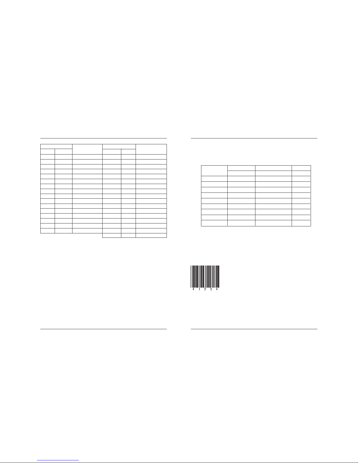
Line Thermal Printer DEP-50
66 67
User’s Manual
Control characte Control character
ASCII Hex
HRI character
ASCII Hex
HRI character
NUL 00 ^U DLE 1 0 ^P
SOH 0 1 ^ A DC1 11 ^Q
STX 0 2 ^B DC2 12 ^R
ETX 0 3 ^ C DC3 1 3 ^ S
EOT 0 4 ^D DC4 1 4 ^T
ENQ 0 5 ^E N AK 1 5 ^U
ACK 06 ^F SYN 16 ^V
BEL 07 ^G ETB 1 7 ^W
BS 08 ^H CAN 18 ^X
HT 0 9 ^ I EM 1 9 ^ Y
LF 0A ^J SUB 26 ^Z
V T 0 B ^ K ESC B ^ A
FF 0C ^ L FS 1C ^ B
CR 0D ^M GS 1D ^C
SO 0E ^ N RS 1E ^D
SI 0F ^O US 1F ^E
DEL 7 F ^T
[CODE 128 additional information]
Code 128 covers all ASCII codes from 0 to 127, and it has three
tables A, B and C that can be used in the same barcode.
Table A: contains ASCII symbols with codes 0 to 95 and control
symbols FNC1, FNC2, FNC3, FNC4, SHIFT, CODEB, CODEC.
Table B: contains symbols with ASCII codes from 32 to 127
and control characters FNC1, FNC2, FNC3, FNC4, SHIFT,
CODEA, CODEC.
Table C: It is used for coding barcode areas that consist only of
numerals. Each symbol gives two digits that are coded with
ASCII codes from 0 to 99. Control characters FNC1, CODEA,
CODEB are also available.
The barcode must start with one of the symbols CODEA, CODEB
or CODEC, that determines which table will be used. If it is
necessary the current table could be changed ater by inserting
one of these symbols in to the barcode.The symbol following SHIFT
character is considered to be from table B, if table A is current,
or from table A, if table B is current. If a symbol that is not valid
for the current table is used, the whole barcode is not printed.
Control symbols are assigned two bytes as follows:
Symbol Code system
Decimal Hexadecimal Text
FNC1 123, 49 7B, 31 {1
FNC2 123, 50 7B, 32 {2
FNC3 123, 51 7B, 33 {3
FNC4 123, 52 7B, 34 {4
CODEA 123, 65 7B, 41 {A
CODEB 123, 66 7B, 42 {B
CODEC 123 , 67 7B, 43 {C
SHIFT 123, 83 7B, 53 {S
{ 123, 123 7B, 7B {{
When the data “123” is printed with the code 39
[Sample Program]
LPRINT CHR$ (&H1D) + “H” + CHR$ (2);
LPRINT CHR$ (&H1D) + “k”;
LPRINT CHR$ (4);
LPRINT “123” + CHR$ (0);
[Print Results]
PDF 417 PDF417 is a two-dimensional stacked barcode symbology capable of
encoding over a kilobyte of data per label. There are three modes
used to compress the barcode data.
Text Compaction mode permits all printable ASCII characters to be
encoded, i.e. values 32 - 126 inclusive in accordance with ISO/IEC
646, as well as selected control characters.
Page 35
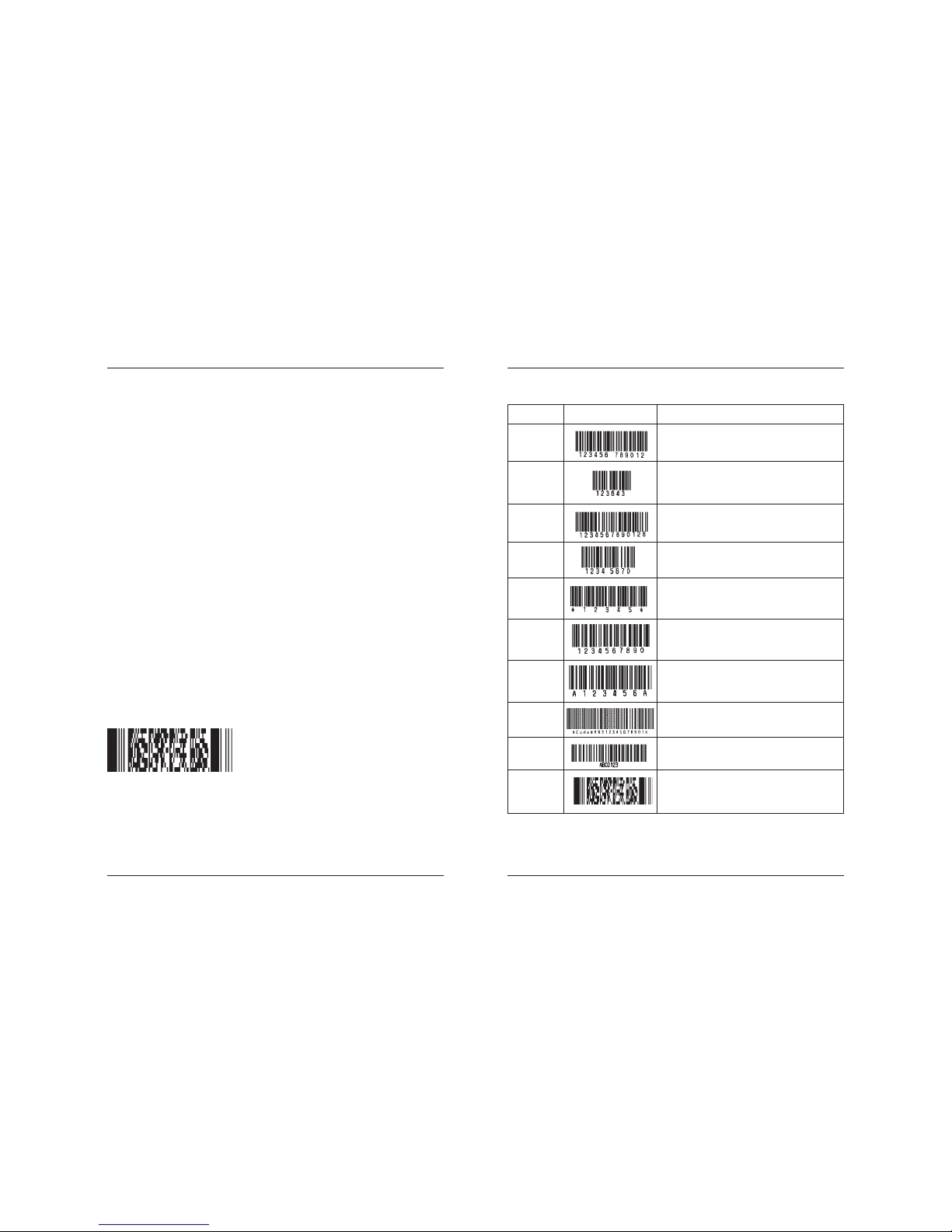
Line Thermal Printer DEP-50
68 69
User’s Manual
Byte Compaction mode permits all 256 possible 8-bit byte values to be
encoded. This includes all ASCII characters value 0 to 127 inclusive
and provides for international character set support.
Numeric Compaction mode permits efficient encoding of long numeric
data digit strings.
A user may define one of 9 error correction levels labeled levels 0 to
8. All error correction levels, except Level 0, not only detect errors but
also can correct erroneously decoded or missing codewords. There
are 2 (Level 0) to 512 (Level 8) codewords per symbol.
At error correction level 0 there are maximum 925 codewords per
symbol available, which can ecode:
Text Compaction mode:
1850 characters (at 2 data characters per codeword).
Byte Compaction mode:
1108 characters at 1.2 data characters per codeword.
Numeric Compaction mode:
2710 characters at 2.93 data characters per codeword.
The user can select whether the printer tries to automatically determine
the appropriate compaction modes or force byte compaction mode.
The first variant of the command is suitable when only text has to be
encoded, while using the second variant all range from 0h to FFh can
be encoded.
[Sample Program]
LPRINT CHR$ (&H1D) + “k”;
LPRINT CHR$ (9) + CHR$ (0);
LPRINT “ABCDEF 0123456789 abcdef”;
LPRINT CHR$(0);
[Print Results]
Type Print Sample Outline of Symbol
UPC-A 12-column fixed-length – barcode
consisting of numerals only
UPC-E 8-column fixed-length barcode consisting
of numerals only. Abbreviated version of
UPC-A
JAN-13 13-column fixed-length barcode –
consisting of numerals only
JAN-8 8-column fixed-length barcode –
consisting of numerals only
CODE39 Variable-length barcode consisting of
alphabets and numerals. The start/stop
code “*” is automatically added.
ITF Even-column variable-length barcode
consisting of numerals only
CODABAR Variable-length barcode consisting of
(NW-7) alpha numerals. Any one of A, B, C and D
is required as the start/stop code.
CODE 93 Variable-length barcode consisting of
alphanumeric and control characters.
CODE 128 Variable-length barcode consisting
of all 128 ASCII code characters.
PDF 417 Two-dimensional stacked barcode
symbology capable of encoding all 256
byte values.
UPC-A, UPC-E, JAN-13 (EAN), JAN-8 (EAN), CODE39, ITF, CODABAR, CODE128, PDF 417
Printing is done depending on barcode specification type, number of print column,
barcode height, width (Magnification), visible code presence, and barcode data specification.
Page 36
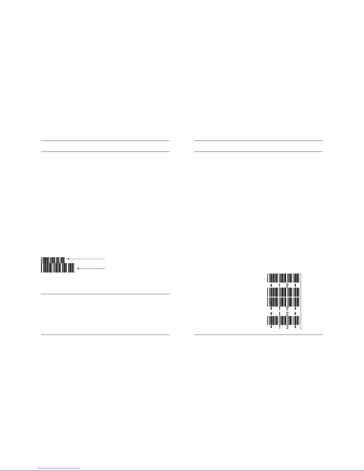
Line Thermal Printer DEP-50
70 71
User’s Manual
GS w n
Selecting the horizontal size (Scale factor) of the barcode
[Code] [1Dh] + [77h] + n
[Range] {2 <= n <= 4}
[Outline] Selecting barcode width.
n denotes the number of dots in fine element width.
[Default]
• The initial value of this width is “3”.
[Sample Program]
LPRINT CHR$ (&H1D) + “h” + CHR$ (30);
LPRINT CHR$ (&H1D) + “w” + CHR$ (2);
GOSUB BC
LPRINT CHR$ (&H1D) + “h” + CHR$ (50);
LPRINT CHR$ (&H1D) + “w” + CHR$ (3);
GOSUB BC
END
BC:
LPRINT CHR$ (&H1D) + “k”;
LPRINT CHR$ (4);
LPRINT “12” + CHR$ (0);
RETURN
[Print Results]
GS h n
Selecting the height of the Barcode
[Code] [1Dh] + [68h] + n
[Range] {1 <= n <= FFh}
[Outline] Selecting barcode height.
n denotes the number of dots in the vertical direction.
[Default]
• The initial value of n is “162”.
Height 30, Magnification 2
Height 50, Magnifikacion 3
GS H n
Selecting of Printing Position of HRI Code
[Code] [1Dh] + [48h] + n
[Range] {0 < = n <= 3}
[Outline] Selecting printing position of HRI code in printing barcodes.
• “n” means the followings.
0 No printing
1 Above the barcode
2 Below the barcode
3 Both above and below the barcode
The HRI code refers to the barcode-turned characters so that you can read them.
[Caution] The HRI code is printed in the font selected with GS f.
Specify before the GS k command.
[Defult]
• The initial value of n is “0”.
[See Also] GS f
[Sample Program]
LPRINT CHR$ (&H1B) + “3” + CHR$ (5);
LPRINT CHR$ (&H1D) + “h” + CHR$ (50);
LPRINT CHR$ (&H1D) + “H” + CHR$ (0);
GOSUB BC
LPRINT CHR$ (&H1D) + “H” + CHR$ (1);
GOSUB BC
LPRINT CHR$ (&H1D) + “H” + CHR$ (2);
GOSUB BC
LPRINT CHR$ (&H1D) + “H” + CHR$ (3);
GOSUB BC
END
BC:
LPRINT CHR$ (&H1D) + “k”;
LPRINT CHR$ (4);
LPRINT “12” + CHR$ (0);
LPRINT CHR$ (&HA);
RETURN
[Print Results]
No Visible
Code
Printed above
Printed below
Printed above
and below
Page 37
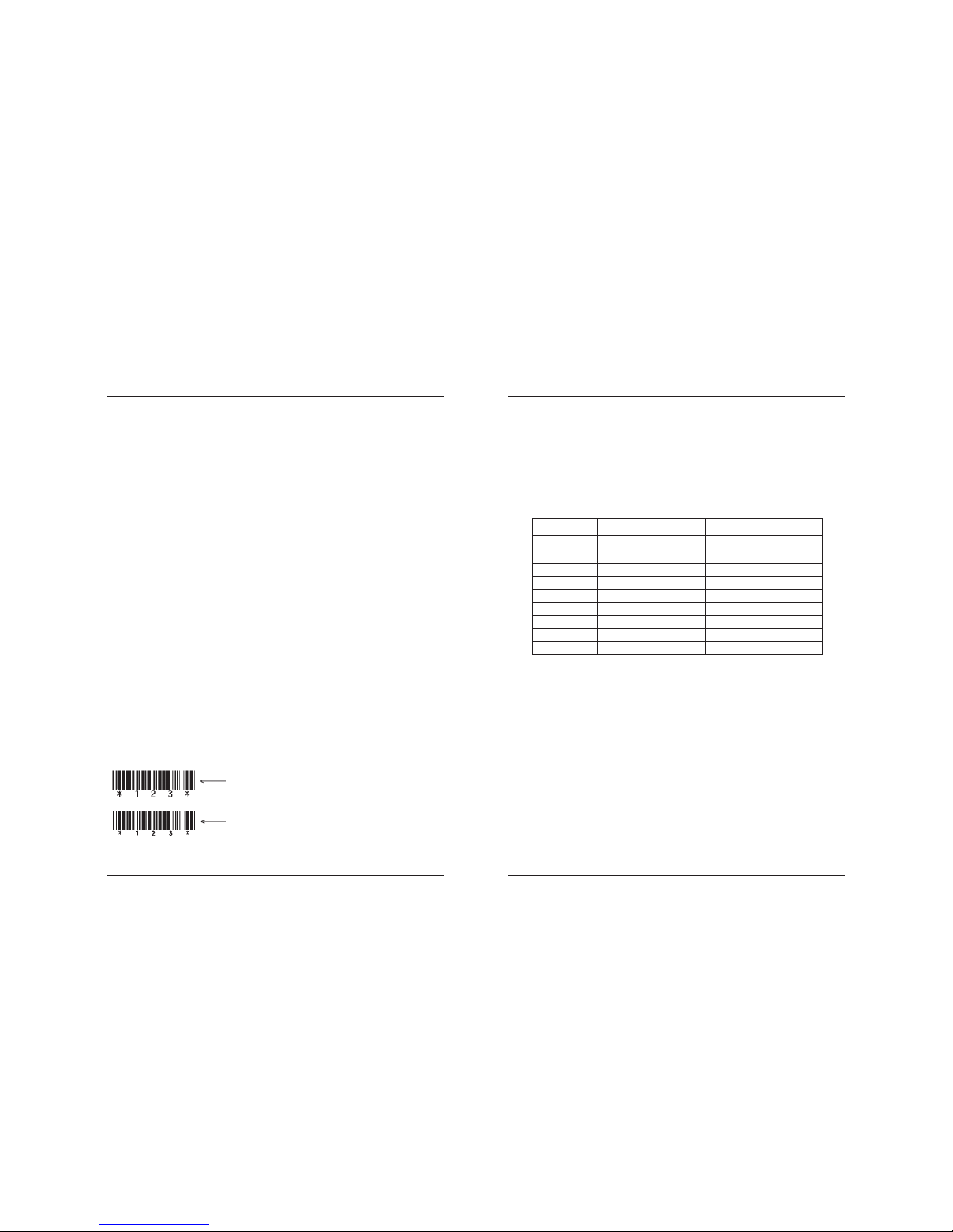
Line Thermal Printer DEP-50
72 73
User’s Manual
GS f n
Selecting the font of HRI code
[Code] [1Dh] + [66h] + n
[Range] n = 0, 1
[Outline] Selecting the font of HRI code in printing barcode.
The type of font can be printed by selecting n is as follows.
0 Font A
1 Font B
The HRI code refers to the barcode-turned characters so that you
can read them.
[Caution] The HRI code is printed at the position specified with GS h.
[Default] The initial value of n is “0 ”.
[See Also] GS H
[Sample Program]
LPRINT CHR$ (&H1D) + “h” + CHR$ (50);
LPRINT CHR$ (&H1D) + “H” + CHR$ (2);
LPRINT CHR$ (&H1D) + “f” + CHR$ (0);
GOSUB BC
LPRINT CHR$ (&H1D) + “f” + CHR$ (1);
GOSUB BC
END
BC:
LPRINT CHR$ (&H1D) + “k”;
LPRINT CHR$ (4);
LPRINT “123” + CHR$ (0);
LPRINT CHR$ (&HA);
RETURN
[Print Results]
FONT A
FONT B
GS p n1 n2 n3
Setting barcode PDF-417 parameters
[Code] [1Dh] + [70h] + n1 + n2 + n3
[Range] {0 < = n1 <= 255}
{0 <= n2 <= 30}
{n3=0; 3 <= n3 <= 90}
[Outline] n1 selects PDF-417 security level. Setting a security level higher
than eight forces the printer to automatically adjusts the security
level according the following table:
EC level EC Codewords Auto Select Level
02 1 4 0-31
2 8 32-63
3 16 64-127
4 32 128-255
5 64 256-511
6 128 512-928
7 256 8 512 -
• Only real data codewords in the security level calculation (any
pad codewords are ignored).
n2 – number of data columns. If n2=0 the number of data columns
is automatically calculated.
n3 – number of rows. If n3=0 the number of rows is auto matically
calculated.
[Caution] If any value is out of range this value remains unchanged.
Thus the other values are changed.
[Default] The initial value of n1 is “9 ” (auto select).
The initial value of n2 is “0 ” (auto select).
The initial value of n3 is “0 ” (auto select).
[See Also] GS k
[Sample Program]
LPRINT CHR$ (&H1D) + “p”;
LPRINT CHR$(4) + CHR$(2) + CHR$(0);
Page 38
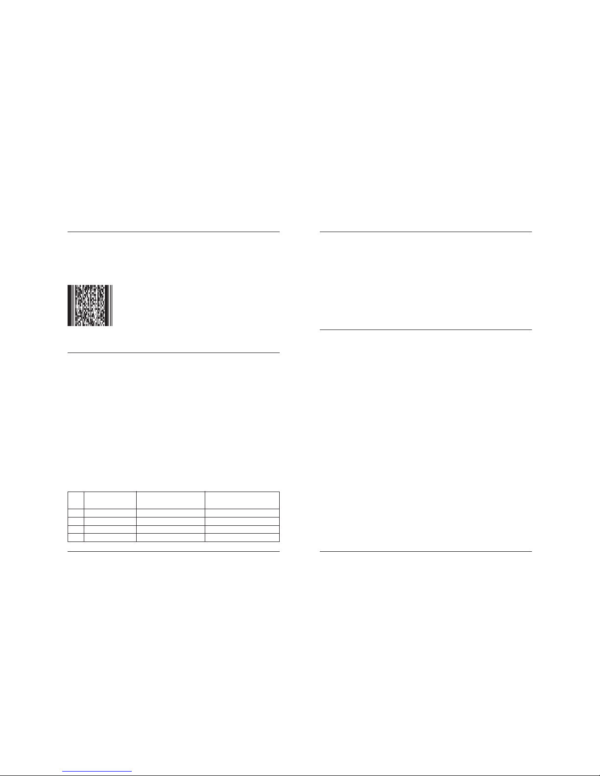
Line Thermal Printer DEP-50
74 75
User’s Manual
LPRINT CHR$ (&H1D) + “k”;
LPRINT CHR$ (9) + CHR$ (0);
LPRINT “ABCDEF 0123456789 abcdef”;
LPRINT CHR$(0);
[Print Results]
GS v0
Printing of raster bit image
[Code] [1Dh] + [76h] + [30h] + m + xL + xH + yL + yH + D1 + … + D
n
[Range] {0 <= m <= 3 ; 48 <= m < = 51}
{0 <= xL <= 255}
{0 <= xH <= 255}
{0 <= yL <= 255}
{0 <= yH <= 255}
{0 <= D
i
<= 255}
[Outline] The value of xH is ignored.
Although yH could be from 0 to 255 the high four bits are ignored,
so yH could actually be from 0 to 15.
xL is the number of bytes in horizontal direction (xL*8 dots).
The number of dots in horizontal direction is equal to yL+yH*256.
The number of data bytes k=xL * (yL+yH*256). However k ust not be
equal to 0 or the bit image will be discarded.
m defines the printing mode of the bit image according to the
following table:
m Mode Dot density in Dot density in
vertical direction horizontal direction
0 Normal 203 DPI 203 DPI
1 Double width 203 DPI 101 DPI
2 Double hight 101 DPI 203 DPI
3 Quadruple 101 DPI 101 DPI
The bit image is defined line by line from left to right. The most significant
bit of each byte is the leftmost dot and the least significant bit is
rightmost dot.
The data that exceeds the printing width of the line is discarded.
The raster bit image could be positioned using the commands ESC \,
ESC $ and GS L.
The raster bit image could be justified using the ESC a command.
If this command is executed during a macro definition, the macro
definition is finished and the command is executed.
GS *
Defining the Download Bit Image
There are two variants of this command depending of the position of switch 5.
If switch 5 is OFF:
[Code] [1Dh] + [2Ah] + n1 + n2 + D
1
+ … + D
n
[Range] {0 < = n1 <= 255}
{0 <= n2 <= 68}
{0 <= Di <= 255}
[Outline] n1 denotes the horizontal size of the bit image
n2 denotes the vertical size of the bit image
There are n1*n2*8 bytes of data in order from top to bottom and
from left to right, n1 bytes in each vertical column of dots.
This command defines a bit image with number of dots determined
by n1 and n2. There are n1*8 dots in horizontal direction and n2*8
number of dots in vertical direction.
If n1 is 0 the downloaded bit image is cleared.
The command GS / is used to print downloaded bit image.
If switch 5 is ON:
[Code] [1Dh] + [2Ah] + n1 + n2 { + n21 + n22 } + D
1
+ … + D
N
[Range] {0 <= n1 <= 7Fh}
{0 <= n2 <= F8h}
{0 <= Di <= FFh}
{1 <= n21+256*n22 <= 544}
[Outline] I f n2 is 0 two more bytes are read. These two bytes then determine
the vertical size of the bit image. The vertical size then is
N= n21+256*n22 rows.
Page 39
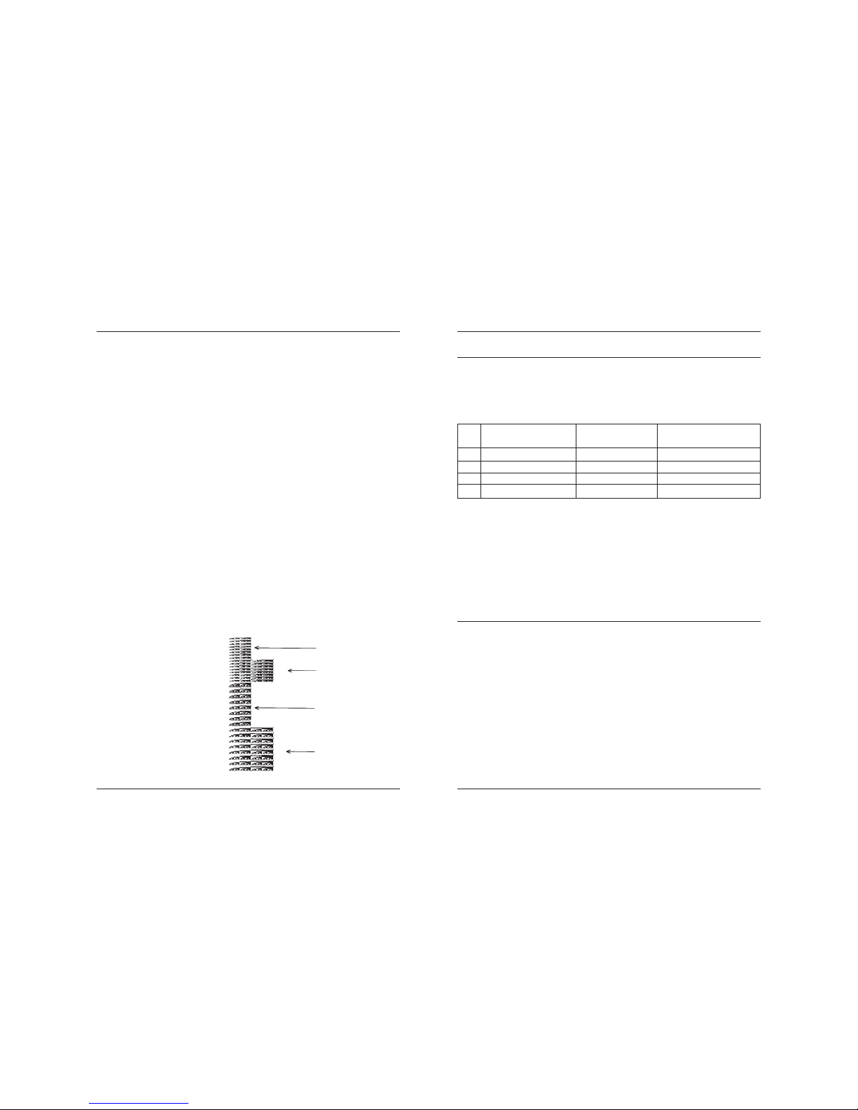
Line Thermal Printer DEP-50
76 77
User’s Manual
If N is the vertical size of the bit image, N=n2 or N= n21+256*n22.
D
i
is the bit image’s data. The number of data bytes is n1*N.
There are n1 bytes in the first row then n1 bytes in the second, etc.
There are N rows in the bit image, and the number of dots in the bit
image is n1*N*8. Each data bit defines one dot, value of “1”
corresponds to black.
If n1 is 0 the downloaded bit image is cleared.
The downloaded bit image remains effective even if the printer is
switched off.
[See Also] GS /
[Sample Program]
GOSUB IMG
LPRINT CHR$ (&H1D) + “/” + CHR$ (0);
LPRINT CHR$ (&H1D) + “/” + CHR$ (1);
LPRINT CHR$ (&H1D) + “/” + CHR$ (2);
LPRINT CHR$ (&H1D) + “/” + CHR$ (3);
END
IMG:
n 1 = 10 : n 2= 5
LPRINT CHR$ (&H1D) + “*”;
LPRINT CHR$ (n1) + CHR$ (n2);
FOR J=1 TO n1*8
FOR I=1 TO n2
LPRINT CHR$ (J);
NEXT I
NEXT J
RETURN
[Print Results]
GS / m
Printing the downloaded bit image
[Code] [1Dh] + [2Fh] + m
[Range] {0 <= m <= 3}
[Outline] Prints download bit image in a mode specified by m.
m Mode Name Dots in Vertical Dots in Horizontal
Direction Direction
0 Normal mode 203 DPI 203 DPI
1 Double wide mode 203 DPI 101 DPI
2 Double high mode 101 DPI 203 DPI
3 DW / DH mode 101 DPI 101 DPI
[Caution]
• When data exist inside the print buffer, this command is ignored.
• When a download bit image has not been defined, this command is
ignored.
• A portion of a download bit image exceeding one line length is not
printed.
[Default]
• The initial value is not specified.
[See Also] GS *
GS :
Starting / Ending Macro Definition
[Code] [1Dh] + [3Ah]
[Outline] Specifying starting / ending macro definition. Means termination when
received while defining a macro.
[Caution] Maximum content available for macro definition is 3823 bytes.
A portion exceeding 3823 bytes is not defined.
• Even with ESC @ (initialization of the printer) having been executed,
defined content is not cleared. Therefore, it is possible to include
ESC @ into the content of macro definition.
• Normal printing operation is carried out even while in macro definition
[Default]
• Initially, Macro is not specified.
[See Also] GS ^
Normal Mode
Double Width Mode
Double Height Mode
Quadruple Mode
Page 40
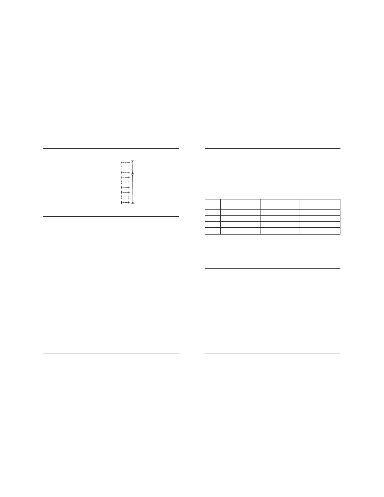
Line Thermal Printer DEP-50
78 79
User’s Manual
Normal Printing during
Macro Definition
[Sample Program]
LPRINT CHR$ (&H1D) + “: “ ;
LPRINT “+___+” + CHR$ (&HA);
LPRINT “ | | “ + CHR$ (&HA);
LPRINT “+___+” + CHR$ (&HA);
LPRINT CHR$ (&H1D) + “: “;
LPRINT CHR$ (&H1D) + “ ^ “;
LPRINT CHR$ (2) + CHR$ (10);
LPRINT CHR$ (0);
Printing during
Macro Execution
FS p n m
Printing the downloaded NV bit image
[Code] [1Ch] + [70h] + n + m
[Range] {0 <= n <= FFh}
{0 <= m <= 3}
{48 <= m <= 51}
[Outline] Printing the downloaded NV bit image defined by FS q command.
m Mode Name Dots in Vertical Dots in Horizontal
Direction Direction
0, 48 Normal mode 203 DPI 203 DPI
1, 49 Double wide mode 203 DPI 101 DPI
2, 50 Double high mode 101 DPI 203 DPI
3, 51 DW / DH mode 101 DPI 101 DPI
“n” is discarded - the printer supports only one NV bit image.
“m” is the bit image printing mode.
FS q n [xL xH yL yH D1 D2 … Dk]
Defining the downloaded NV bit image
There are two variants of this command depending of the position of switch 5.
If switch 5 is OFF:
[Code] [1Ch] + [71h] + n + xL + xH + yL + yH + D1 + D2 + … + Dk
[Range] {0 <= n <= FFh}
{0 <= xL <= FFh}
{0 <= xH <= FFh}
{0 <= yL <= FFh}
{0 <= yH <= FFh}
{0 <= D <= FFh}
[Outline] This command defines the specified NV (non volatile) bit image. The
bit image is stored into the flash.
n is ignored – the printer supports only one bit image.
xL and xH denote the horizontal size of the NV bit image as
(xL + xH × 256) × 8 dots.
[Print Results]
GS ^ n1 n2 n3
Executing the Macro
[Code] [1Dh] + [5Eh] + n1 + n2 + n3
[Range] {0 <= n 1 <= FFh}
{0 <= n2 <= FFh}
{0 <= 3 <= 1}.
[Outline] Executing contents defined in macro.
• “n1~n3” indicate as follows:
n1 : The number of times of macro execution
n2 : Waiting time on macro execution
Waiting time of n2 x 100 msec is given for every execution.
n3 : Macro execution mode
0 Continuous execution
1 Execution by LFSW
Continuous execution: The Macro is executed n1 times continuously
at the time intervals specified by n2.
Execution by FEED S: After waiting for lapse of time specified by n2,
the LF switch is waited to be pressed. When it is pressed, the macro
is executed once. This action is repeated n1 times.
[Caution] • When this command is received while in macro definition,
suspension of macro definition is indicated. At this time, the defined
content is cleared.
• No execution takes place when macro is held undefined or n1=0.
• While in macro execution with n3=1, paper feed with the LF SW is
not available.
[Default] • Initially, this command is not specified.
[See Also] GS :
Page 41

Line Thermal Printer DEP-50
80
yL and yH denote the vertical size of the NV bit image as
(yL + yH × 256) × 8 dots.
Total amount of data defining the bit image is
(xL + xH × 256) × (yL + yH × 256) × 8 bytes.
[Details] The maximum printable size of the NV bit image is 384 × 512 dots. This
corresponds to (xL + xH × 256) < 48 and (yL + yH × 256) < 64.
The exceeding data is read but discarded.
The order of the data is from top to bottom and then from left to right,
(yL + yH × 256) bytes in each vertical column of dots.
The printer will become busy before each writing cycle in the NV
memory. Any data sent while the printer is busy may not be
processed and therefore could be lost.
xL = xH = yL = yH = 0 clears the downloaded bit image.
If switch 5 is ON:
[Code] [1Ch] + [71h] + n + xL + xH + yL + yH + D1 + D2 + … + Dk
[Range] {0 <= n <= FFh}
{0 <= xL <= FFh}
{0 <= xH <= FFh}
{0 <= yL <= FFh}
{0 <= yH <= FFh}
{0 <= D <= FFh}
[Outline] This command defines the specified NV (non volatile) bit image. The
bit image is stored into the flash.
n is ignored – the printer supports only one bit image.
xL and xH denote the horizontal size of the NV bit image as
(xL + xH × 256) × 8 dots.
yL and yH denote the vertical size of the NV bit image as
(yL + yH × 256) dots.
Total amount of data defining the bit image is
(xL + xH × 256) × (yL + yH × 256) bytes.
[Details] The ma ximum printable size of the NV bit image is 384 × 512 dots.
This corresponds to (xL + xH × 256) < 48 and (yL + yH × 256) < 512.
The exceeding data is read but discarded.
The order of the data is from left to right and then from top to bottom,
(xL + xH × 256) bytes in each horizontal row of dots.
The printer will become busy before each writing cycle in the NV
memory. Any data sent while the printer is busy may not be
processed and therefore could be lost.
xL = xH = yL = yH = 0 clears the downloaded bit image.
 Loading...