

CAS BW-6, BW Series, BW-30, BW-60, BW-150 Service Manual
...
- 1 -
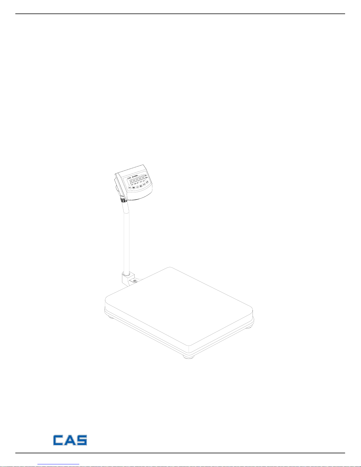
BATTERY WEIGHING SCALE
BW-SERIES
SERVICE MANUAL
Revision : 2005. 5. 9

- 2 -
Table of Contents
INTRODUCTION 3
TECHNICAL SPECCIFICATION 3
INSTALLATION & CONNECTION 4
TEST MODE 5
CALIBRATION MODE 7
SET MODE 9
SCHEMATIC DIAGRAM 10
P.C.B DIAGRAM 11
CONNECTION DIAGRAM 13
PART LIST 14
EXPLODED VIEW 19
ERROR MESSAGE & TROUBLE SHOOTING 23
- 3 -
INTRODUCTION
The service manual is the specification for the BW-SERIES. They have been
designed with CAS reliability under rigid quality control and with outstanding
performance.
This manual includes basic technical about composition of hardware and program
function.
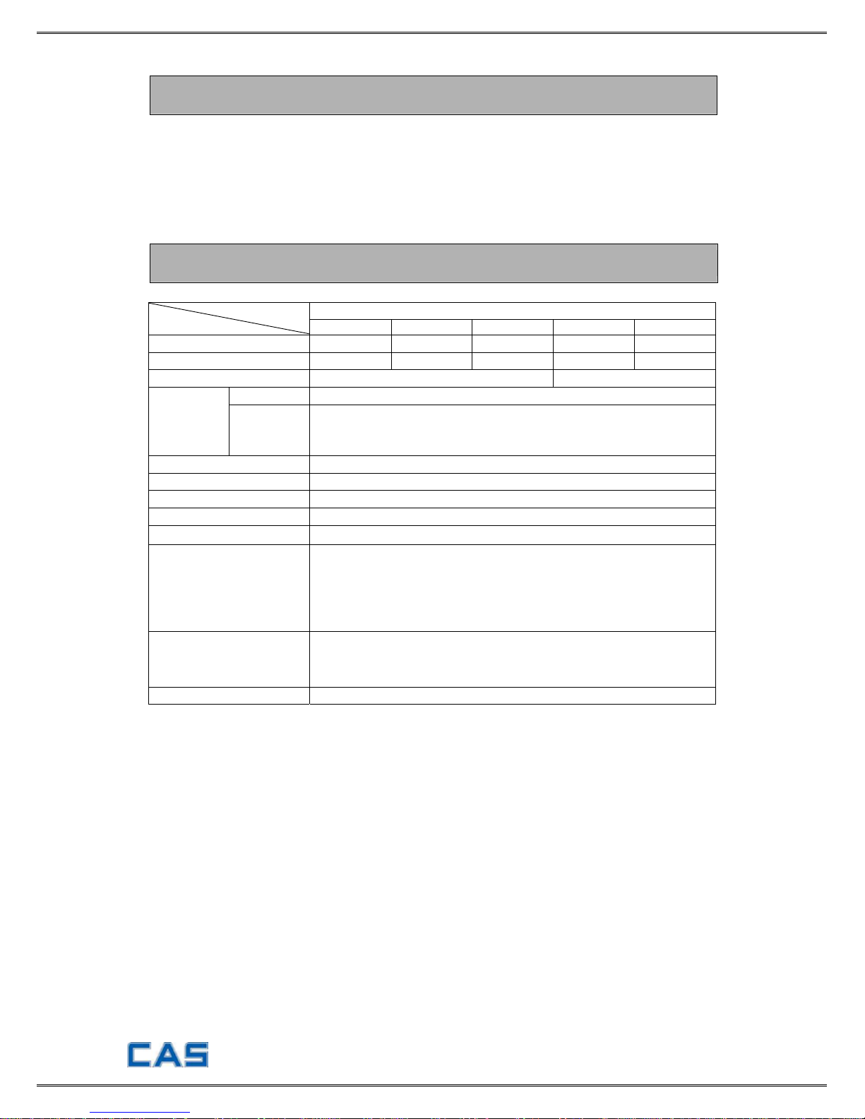
TECHNICAL SPECIFICATION
BW SERIES
Model Item
BW-6 BW-15 BW-30 BW-60 BW-150
Maximum capacity
6kg 15kg 30kg 60kg 150kg
Minimum division
0.002kg 0.05kg 0.01kg 0.02kg 0.05kg
Platform size
280(W) X 280(D) X 80(H)
425(W) X 545(D) X105(H)
Standard ON/OFF, ZERO, TARE, HOLD, COUNT, HIGH/LOW comparing
Function
Option
1. RS-232C
2. BACK LIGHT
3. DC 1.2V(6EA) Recharging Battery, DC 12V Adaptor
Temperature range
-10℃ ~ 40℃
Max. Tare range Max. capacity
Rezero range ±2% of max. capacity
Initial zero range ±10% of max. capacity
Weight display type
5 place LCD(Char. size 23.5 ㎜)
Character display
1. Stable (○)
2. High, Normal, Low (HI, OK, LO)
3. Battery discharge (BAT)
4. quantity unit(PCS)
5. Weight unit(㎏)
Power
1. DC7.2V(6EA SIZE "C") 2200 ㎃ h Recharging battery
2. DC9V (6EA SIZE “C”) Mn, Alkaline battery
3. DC12V 850 ㎃ AC Adapter
Consumption Approx. 0.15W
- 4 -
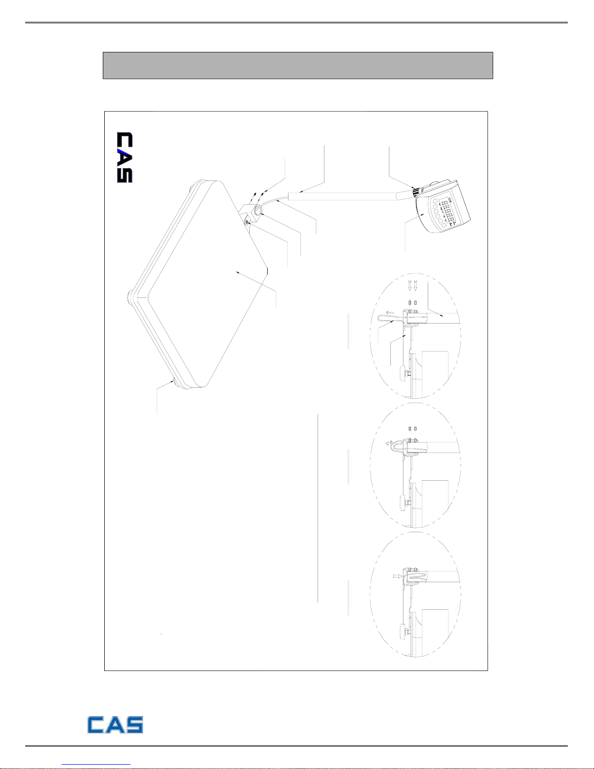
INSTALLATION & CONNECTION
Installation
INDICATOR
LEVELING GAUGE
How to install the BW-series
1. Open the box with care because indicator is
connected to the scale with load cell wire.
2. Turn the post knob so as to fix indicator.
3. Pull down the wire out of post pipe and insert
the post pipe to the post bracket. (Refer to fig. 1)
4. Fasten the post pipe with two bolts. (Refer to fig. 1)
A long bolt should be connected to the upper side.
5. Insert the wire to the post pipe. (Refer to fig. 2.3)
6. If the scale is not properly level, please adjust
4 leg(adjusting bolt) at the bottom of the scale
so as to center the bubble of the leveling gauge
Note: Place the scale on a flat and stable surface.
inside the indicated circle.
FIG. 3
ADJUST
FIG. 2
WIRE
FIG. 1
POST BRACKET
PLATFORM
POST KNOB
POST PIPE
POST BRACKET
LOAD CELL WIRE
BOLT
POST PIPE
- 5 -
Serial Interface (RS-232C)
■ Connecting with PC
RXD 1ㅇ
---------------------------
ㅇ 2 Transmit Data
TXD 2ㅇ
---------------------------
ㅇ 3 Receive D ata
GND 5ㅇ
---------------------------
ㅇ 7 Signal Ground
┌─
ㅇ 4 Request to Send
├─
ㅇ 5 Clear to Send
├─
ㅇ 6 Data Set Ready
├─
ㅇ 8 Carrier Detect
└─
ㅇ 20 Data Terminal Ready
9 pin port (Male) 25 pin port of PC (Female)
RS-232C port of BW-SERIES
RXD 1ㅇ
---------------------------
ㅇ 3 Transmit Data
TXD 2ㅇ
---------------------------
ㅇ 2 Receive D ata
GND 5ㅇ
---------------------------
ㅇ 5 Signal Ground
┌─
ㅇ 1 Carrier Detect
├─
ㅇ 4 Data Terminal Ready
├─
ㅇ 6 Data Set Ready
├─
ㅇ 7 Request to Send
└─
ㅇ 8 Clear to Send
9 pin port (Male) 25 pin port of PC (Female)
RS-232C port of BW-SERIES
■
Connecting with Sub-display (CD-SERIES)
RXD 1ㅇ
---------------------------
ㅇ 2 Transmit Data
TXD 2ㅇ
---------------------------
ㅇ 3 Receive D ata
GND 5ㅇ
---------------------------
ㅇ 7 Signal Ground
9 pin port (Male) 9 pin port of Sub-display
(Male)
RS-232C port of BW-SERIES
TEST MODE
Moving method
Open the top cover of indicator and power on with pressing CAL switch in the left
top. At that time, LCD screen shows “ZEro=tESt tArE=CAL” message and pressing
‘Zero’ key moves to Test 1.
Test menu (tESt 1 ~ tESt 4)
TEST 1: Liquid crystal display test
TEST 2: A/D conversion test
TEST 3: Key test
TEST 4: RS-232C communication test
- 6 -
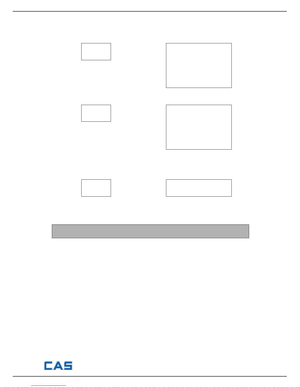
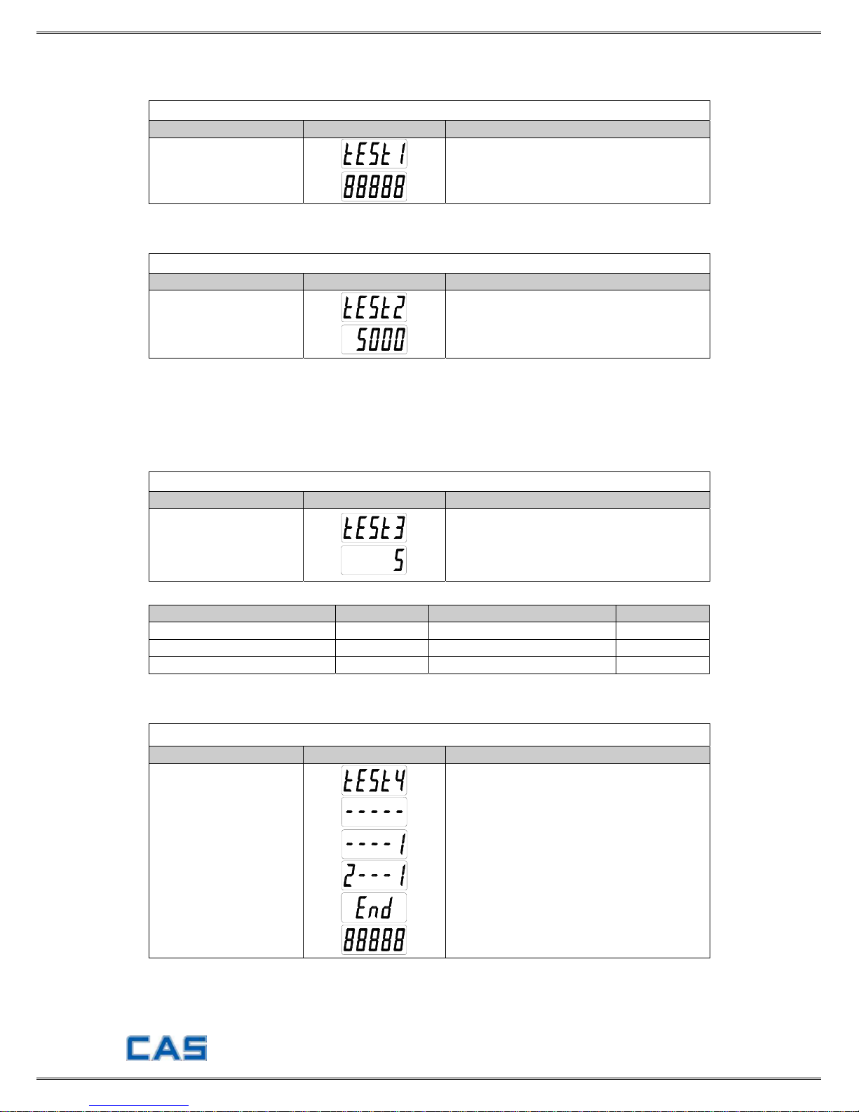
TEST 1 (Enter ‘TEST’ mode to start TEST 1.)
FUNCTION : Liquid crystal display Test
KEY LC DISPLAY DESCRIPTION
ENTER Key : Next menu
Display TEST 1 state.
TEST 2
FUNCTION : A/D conversion test
KEY LC DISPLAY DESCRIPTION
ENTER Key : Next menu
ZERO Key :
Use to set the current
value to “0”
Display TEST 2 state.
Display the digital value corresponding to
current weight.
Note 1. ▶ Check whether the digital value is changing whenever you load or unload
the weight on the platter. If the digital value is fixed or zero is
displayed,
please check the connection of loadcell.
TEST 3
FUNCTION : Key test
KEY LC DISPLAY DESCRIPTION
ENTER key : Next menu
Other key : Test execution
Display TEST 3 state.
Press the key to be tested and the No. of
key mode should be identifying with code
of key as the follows.
<KEY CODE>
KEY CODE KEY CODE
* 1 GROSS /NET 4
ZERO 2 HOLD or kg/lb 5
TARE 3
TEST 4
FUNCTION : RS-232C communication test
KEY LC DISPLAY DESCRIPTION
ENTER key :
Move to weighing mode.
Other key :
Execute data transmission
to a computer.
Display TEST 4 state.
Waiting for transmission and reception.
Received : None, Transmitted : 1
Received : 2, Transmitted : 1
Press ENTER key.
When this test is completed, it is
automatically moved to NORMAL MODE.
▶ Note 1. Connect the computer COM port with RS232C connector of indicator before
running this test.
▶ Note 2. Send No. 2 in computer keyboard and check if indicator receives No.2 send No. 1
in indicator keyboard and check if computer receives No.1
- 7 -
CALIBRATION MODE
Moving method
Open the top cover of indicator and power on with pressing CAL switch in the left
top. At that time, LCD screen shows “ZEro=tESt tArE=CAL” message and pressing
‘TARE’ key moves to CAL 1.
Calibration menu (CAL 1 ~ CAL 5)
CAL 1 : Maximum Capacity Set
CAL 2 : Minimum Division Set
CAL 3 : Setting Weight in Span Calibration
CAL 4 : Zero Calibration
CAL 5 : Span Calibration
Digit input method
NET/GROSS Key : Increase the first place value by 1.
TARE Key : Move to the left by 1 place.
ZERO/MODE Key : Set the inputted value to “0”.
ENTER Key : Move to the next menu.
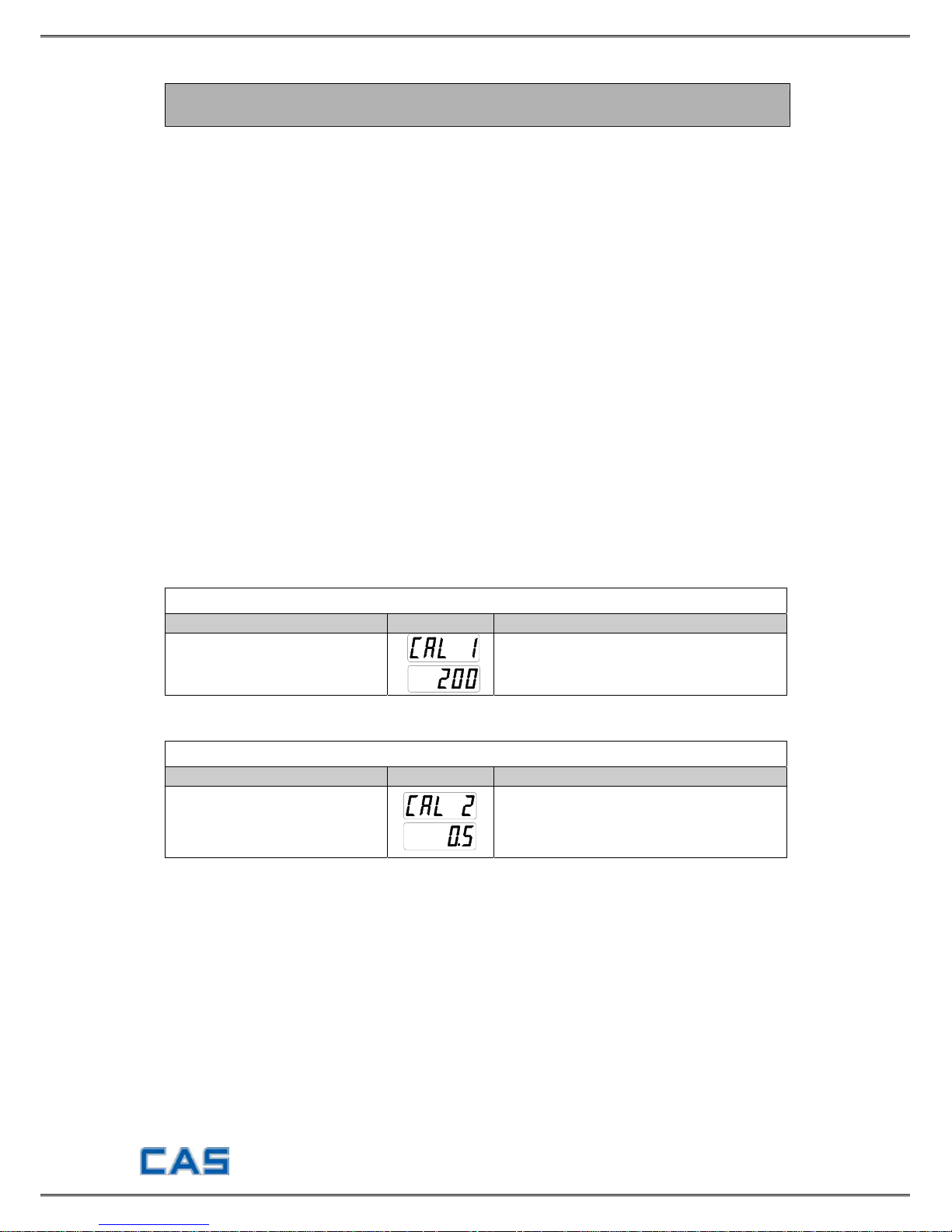
CAL 1
FUNCTION : Maximum Capacity Set (Range : 1 ~ 99,999)
KEY LC DISPLAY
DESCRIPTION
Input by digit input method.
ENTER : save and go to next menu
CAL 1 condition
200 Kg
CAL 2
FUNCTION : Minimum Division Set (Range : 0.001 ~ 50)
KEY LC DISPLAY
DESCRIPTION
NET/GROSS key:
Input the next division
TARE key:
Input the previous division
ENTER key: Move to the next menu
CAL 2 condition
0.5 Kg
▶ Note 1. The minimum division means the value of one division.
▶ Note 2. External resolution is obtained by dividing the min. division by the
maximum capacity. Set the resolution to be within 1/10,000.
▶ Note 3. The maximum capacity/minimum division is over 10,000, error message
“CH 11” will occur.
- 8 -
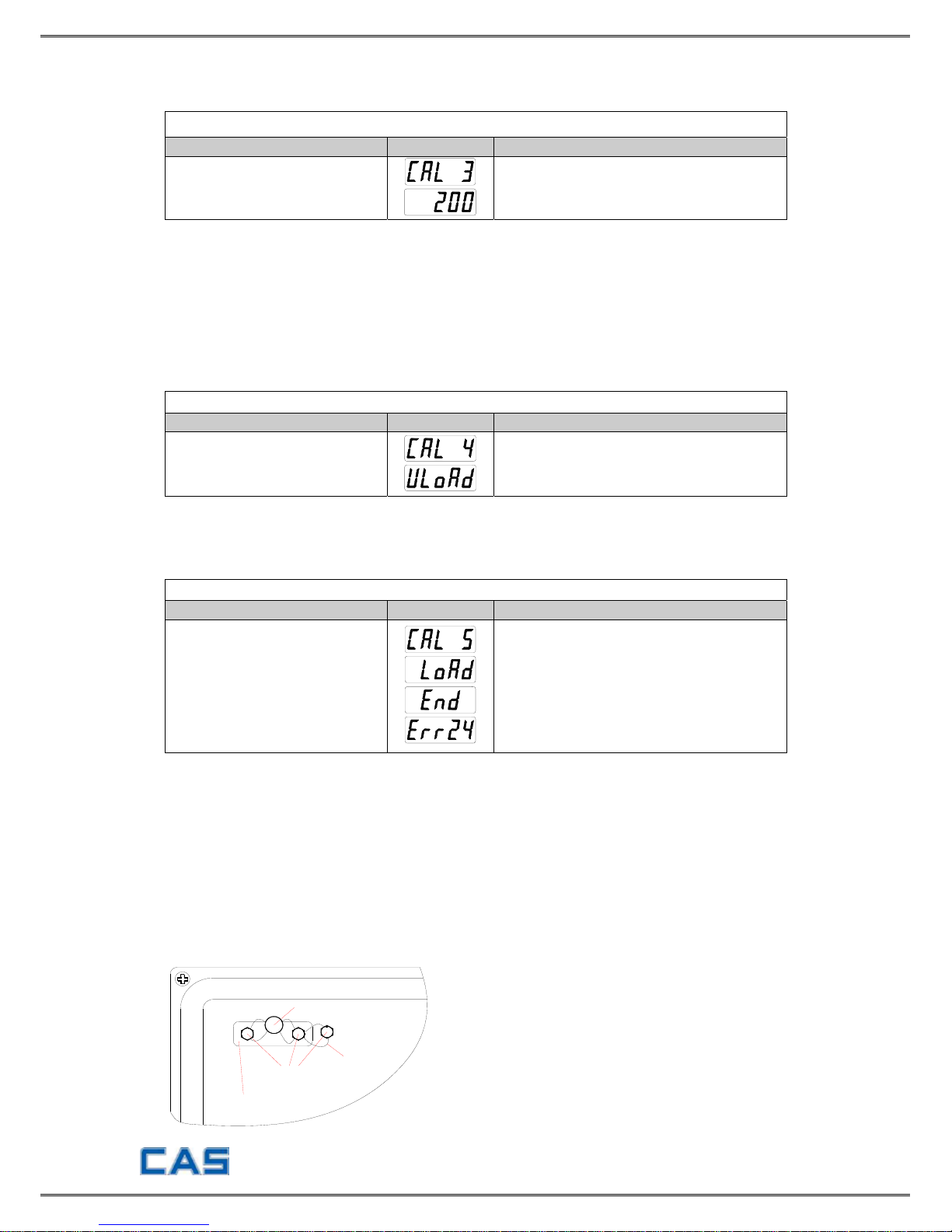
CAL 3
FUNCTION : Setting Weight In Span Calibration
KEY LC DISPLAY
DESCRIPTION
Input by digit input method.
ENTER : save and go to next menu
CAL 3 condition
200 Kg
▶ Note 1. The span weight shall be within 10-100% of maximum capacity.
The initial span weight is 100% of max. capacity but if the current span
weight is different from it, input the desired weig ht again.
▶ Note 2. The span weight shall be above 10% of maximum capacity.
If not so, an error message “ERR22” is shown.
▶ Note 3. Never install the span weight higher than maximum capacity because
an error message “ERR23” is shown.
CAL 4
FUNCTION : Zero Calibration
KEY LC DISPLAY
DESCRIPTION
ENTER key : Move to next menu
after zero calibration
Empty the platform and when LCD screen
shows “ULOAD”, press ‘ENTER’ key.
After completing zero calibration, it will be
automatically moved to CAL 5.
▶ Note 1. Zero calibration is performed automatically by program.
Loadcell output is automatically adjusted within 0.05mV and 5mV.
CAL 5
FUNCTION : Span Calibration
KEY LC DISPLAY
DESCRIPTION
ENTER key : Span calibration
Put the weight set in CAL3 on platform
and press ‘ENTER’ key.
Span calibration is terminated.
Error occurrence.
Move into initial menu automatically.
▶ Note 1. Display “END” message and move into the NORMAL MODE at completion
of span calibration
▶ Note 2. At occurrence of ERR24, reset by lowering the resolution.
Sealing method
Perform the sealing as shown in the below figure after the calibration is completed.
Open the top cover.
Cover CAL switch in the left top of cover with sealin g plate and screw 2 sealing bolt.
Connect the sealing wire as follows and compress the sealing lead.
SEALING WIRE
SEALING PLATE
SEALING BOLT
SEALING SOLDER
 Loading...