

CAS AD series Service Manual

AD series
SERVICE MANUAL
CAS

THE CONTENTS CHAPTER-I THE GENERAL INTRODUCTIONS
A.... PREFACE 4
B.... THE PRECAUTIONS 4
C.... THE SPECIFICATIONS 4
D....SEALING METHOD 5
CHAPTER-II THE CALIBRATIONS
A.... SET THE CALIBRATION MODE
.....................................................
6
B.... THE MODES
..............................................................................
7
B. 1.. THE MODE 1
............................................................................
8
B. 2.. THE MODE 2
............................................................................
8
B. 3.. THE MODE 3
............................................................................
8
B. 4.. THE MODE 4
............................................................................
8
B. 5.. THE MODE 5
...........................................................................
8
C.... THE SPAN CALIBRATION
............................................................
9
C.1..SET THE CALIBRATION MODE
..................................................
9
C. 2.. ENTRY OF THE MODE 4 9
C.3..SPAN CALIBRATION
.......................................................................................
10
C. 4.. CONFIRMATION OF THE SPAN
.........................................................................
10
D.... THE SPAN CALIBRATION FROM THE REPAIR
.................................
11
D. 1.. SET THE CALIBRATION MODE
...................................................
11
D. 2.. CHECK OF THE INITIAL ZERO AND SPAN
.....................................
11
D.3..THE SPAN CALIBRATION
.........................................................
11
D.4.. CONFIRMATION OF THE SPAN
................................................
12
E.... THE SPAN CALIBRATION WITH A PARTIAL LOAD
...........................
13
E. 1.. SET THE CALIBRATION MODE
...................................................
13
E.2..ENTRY OF A PARTIAL CALIBRATION
.........................................
13
E. 3.. INPUT OF A PARTIAL LOAD BY PERCENTAGE
...............................
13
E.4..THE SPAN CALIBRATION
.........................................................
14
E. 5.. CONFIRMATION OF THE SPAN
....................................................
14
CHAPTER-III THE PART REPLACEMENTS
A.... REPLACEMENT OF THE LOAD CELL
............................................
15
A. 1.. REPLACEMENT OF THE LOAD CELL
...........................................
15
A.2..CORRECTION OF THE ECCENTRICITY
......................................
15
A.3..THE SPAN CALIBRATION
.......................................................
15
B....REPLACEMENT OF THE ANALOG MODULE
.................................
16
B.1..REPLACEMENT OF THE ANALOG MODULE
...............................
16
B.2..THE SPAN CALIBRATION FOR THE ANALOG MODULE
................
16
C....REPLACEMENT OF THE DIGITAL MODULE
..................................
16
C.1..REPLACEMENT OF THE DIGITAL MODULE
................................
16
C.2..THE INPUTS FOR THE DIGITAL MODULE
...................................
16
CHAPTER-IV THE TRANSFORMER
A.... THE TRANSFORMER
..................................................................
17

CHAPTER-V THE SCHEMATICS AND THE DIAGRAMS
A.1..MAIN CIRCUIT DIAGRAM
..........................................................
19
A.2..DISPLAY CIRCUIT DIAGRAM
.....................................................
20
B....WIRING DIAGRAM
....................................................................
21
C....PARTS LOCATION
.....................................................................
22
CHAPTER-VI THE ERROR MESSAGES
A.... THE ERROR MESSAGES
...............................................................
23
A. 1.. ERR 1
...................................................................................
23
A. 2.. ERR 2
....................................................................................
23
A
. 3.. ERR 10
..................................................................................
23
A. 4.. ERR 11
...................................................................................
23
A. 5.. ERR 12
...................................................................................
23
A. 6.. ERR 13
...................................................................................
23
CHAPTER-VII THE OTHERS
A.... FOR THE SERIAL INTERFACE
.......................................................
24
A.1..THE COMMUNICATION AGREEMENTS
.....................................
24
A.2..THE WIRE CONNECTIONS
.......................................................
24
A.3..THE PROTOCOL
....................................................................
25
A. 4.. THE DATA TRAINS
.................................................................
25
B....EXPLODED VIEW
.......................................................................
27
C.... FULL PARTS LIST
.......................................................................
28
CHAPTER-VIII APPENDIX-I
A.... INPUT CODES FOR THE DIGITAL MODULE
.....................................
32
A. 1 THE ALTERNATIVE KEY FUNCTIONS
.........................................
32
A.2 INPUTS FOR WEIGH CONDITION CODES
....................................
32
A. 3 THE SPAN CALIBRATION
..........................................................
33
CHAPTER-I THE GENERAL
INTRODUCTIONS
A. PREFACE
Thank you for the purchasing of CAS scale.
This scale has been designed with CAS reliability, under rigid quality control
and with outstanding performance.
Your departments can enjoy with this high quality reliable CAS product.
We believe that your needs will be satisfied and you will have proper reliability
with in variable weight.
This manual will help you with proper operations and care of the AD series.
Please keep it handy for the future references.
B. THE PRECAUTIONS
1.
Check the power voltage.
2.Place the scale on a flat and stable surface.
3.
Level the scale with four adjusters.
Bubble of the level should be centered.
4.Plug into AC outlet 10 minutes before operations.
5.Keep the scale away from strong E.M.I, noises.
6.This scale must be installed in a dry and liquid free environment.
7.Do not expose the scale to sudden temperature change.
8.Do not expose the scale to sudden impact.
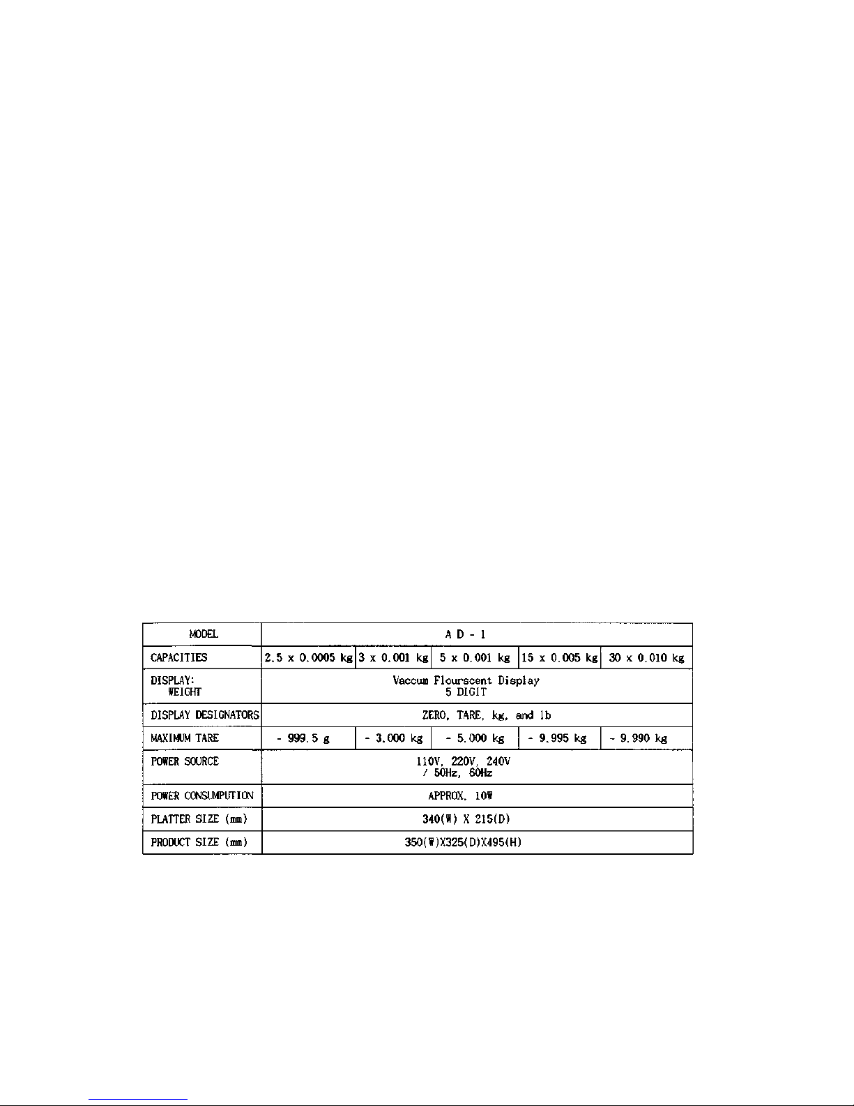
C. THE SPECIFICATIONS
Notice : specifications are subject to change for improvement without notice.
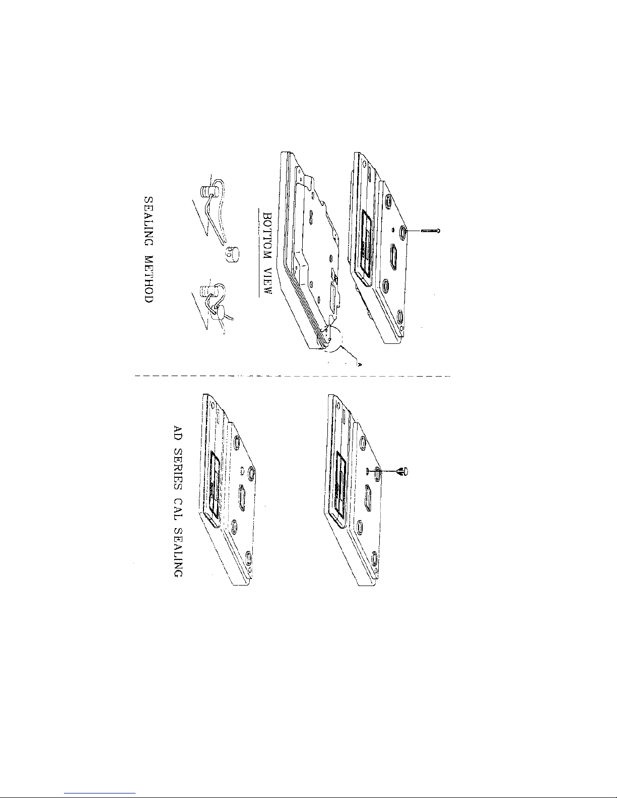
D. SEALING METHOD
CHAPTER-II THE CALIBRATIONS
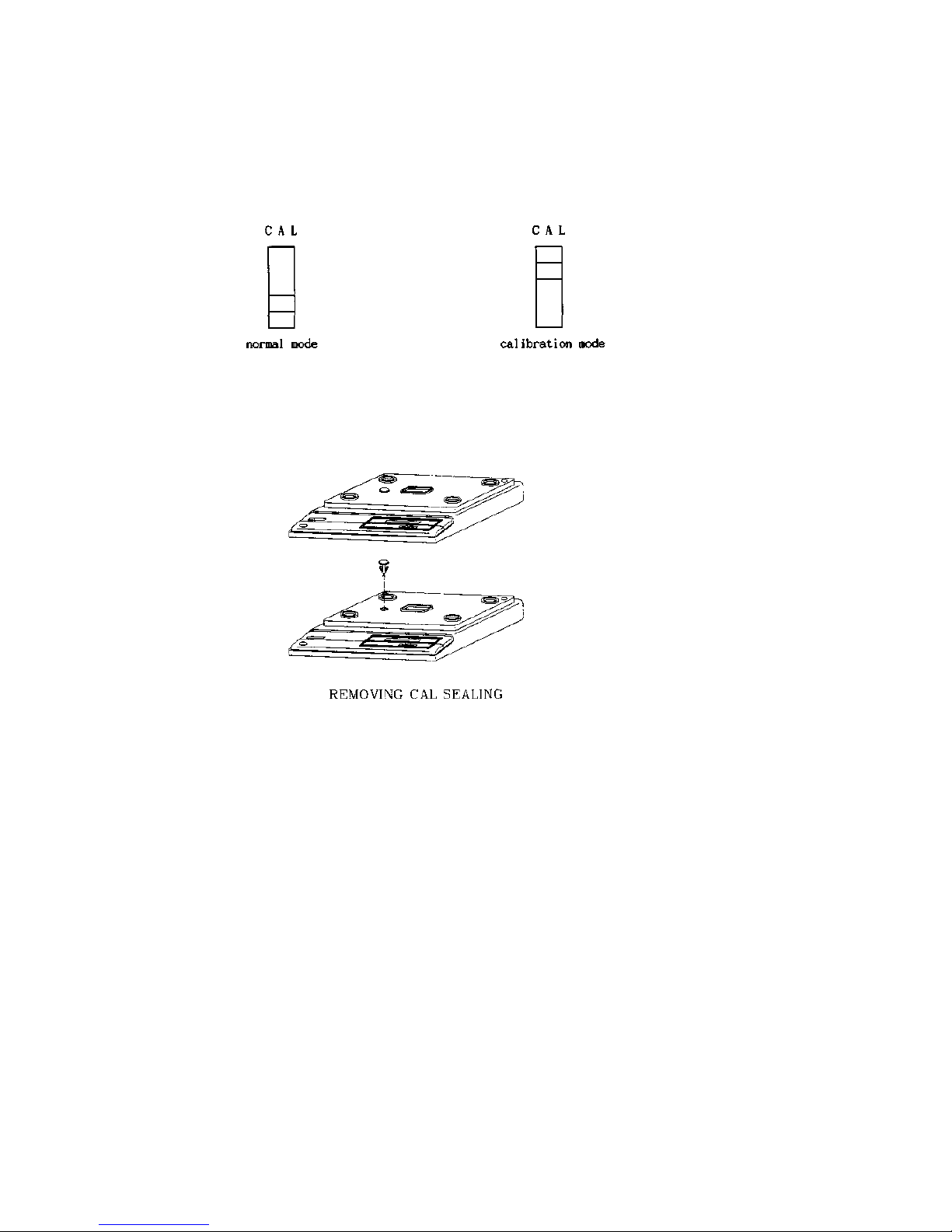
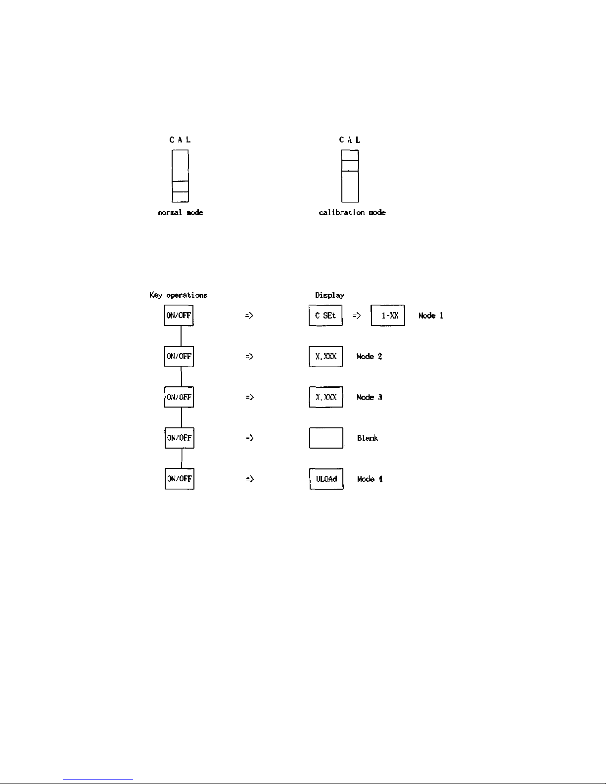
A. SET THE CALIBRATION MODE
The CAL switch is located underneath of the hole left of the upper case.
1.
Remove a seal cover.
2.
Slide CAL switch to the CAL position.
3. Plug into the AC outlet.
-> The display shows
"CAL"
three times.

B. THE MODES
This scale
has
5 modes for set of weighing condition and for set of the span calibration.
These 5 modes are described as below.
B. 1 THE MODE 1
In this mode 1, a various weighing conditions can be set.
Weighing conditions for capacity, external resolution, and decimal point etc.
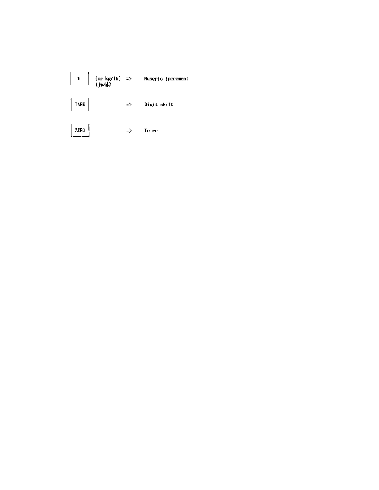
In this mode, below three keys have an alternative functions respectively.
* For entire sets of weighing conditions, please refer to the APPENDIX I.
B.2 THE MODE 2
In this mode 2, intacted A/D reading is shown on the display.
This intacted A/D reading is necessary to check an initial zero point and to check a span range both, when either a load cell was replaced or
an analog module was replaced.
Unless above both replacement, skip to this mode 2 by pressing the 'ON/OFF" key.
B.3 THE MODE 3
In this mode 3, a calibrated A/D reading is shown on the display.
This mode helps to do a fine span trimming without span calibration(MODE 4).
B.4 THE MODE 4
In this mode 4, an actual span of the scale is calculated by digital calibration method. The sign "ULOAd", means empty the platter, "LOAd"
means, load a full weight on the platter.
* If you want to quit this span calibration, press the "ZERO" key while either "ULOAd " or "LOAd" is shown on the display.
B.5 THE MODE 5
Finally in this mode 5, a fine span trimming is obtained after a span calibration(MODE 4)
C. THE SPAN CALIBRATION MODE 4) C. 1 SET THE
CALIBRATION MODE
The CAL switch is located underneath of a hole left of the upper case.
1.
Remove a seal plate.
2.
Slide CAL switch to the CAL position.
3. Plug into the AC outlet.
-> The display shows "CAL" three times.
C.2 ENTRY OF THE MODE 4
Enter to span calibration mode as below

C.3 SPAN CALIBRATION
In this MODE 4, "ULOAd" is shown on the display.
1. Press the "ON/OFF" key,
-> The display shows a count down 9 to 0. -> "LOAd" is shown on the display.
2.
Load a full weight on the platter gently.
3.
Press the "ON/OFF" key,
-> The display shows a count down again, -> The display shows "End" and be
blanked.
4. Remove a full load from the platter.
*If you want to quit this span calibration, press the "ZERO" key while either "ULOAd " or "LOAd" is shown on the display.
With above operations, the span calibration is finished, and following paragraph A. 4 guides to confirm the span and to do fine trimming for
more accurate weighing.
However when fine trimming is not needed, press the "ZERO" key to skip following MODE 5 and exit to the normal mode.
C.4 CONFIRMATION OF THE SPAN(MODE 5)
This mode 5 is only available after performance of a previous span calibrationfmode 4).
1. Press the "TARE" key,
-> The display shows the initial zero point.
2.
Press the "ZERO" key to read a span(net weight),
-> The display shows "0".
3.
Load a full weight on the platter gently.
Unless the display has 30,000 +-1, for more accurate weighing, perform a fine trimming.
4. If a span is bigger than 30,000, press the "*" or "kg/lb" key twice for a decreasing
and less than 30,000, press the "*" or "kg/lb" key and press the "TARE" key for an
increasing.
Whenever you press these keys, a count can be changed.
5.
At the end of fine trimming, press the "ON/OFF" key.
6.
Press the "ZERO" key to exit and go to the normal mode.
-> Weight display shows "Err 2", but actually this error message is not a real error, it prompts only return CAL switch to the normal
position.
7. Return the CAL switch to the normal position(initial position).
 Loading...